EP2913295A1 - Water server - Google Patents
Water server Download PDFInfo
- Publication number
- EP2913295A1 EP2913295A1 EP13848654.3A EP13848654A EP2913295A1 EP 2913295 A1 EP2913295 A1 EP 2913295A1 EP 13848654 A EP13848654 A EP 13848654A EP 2913295 A1 EP2913295 A1 EP 2913295A1
- Authority
- EP
- European Patent Office
- Prior art keywords
- raw water
- water tank
- supply line
- line
- water
- Prior art date
- Legal status (The legal status is an assumption and is not a legal conclusion. Google has not performed a legal analysis and makes no representation as to the accuracy of the status listed.)
- Withdrawn
Links
Images


Classifications
-
- B—PERFORMING OPERATIONS; TRANSPORTING
- B67—OPENING, CLOSING OR CLEANING BOTTLES, JARS OR SIMILAR CONTAINERS; LIQUID HANDLING
- B67D—DISPENSING, DELIVERING OR TRANSFERRING LIQUIDS, NOT OTHERWISE PROVIDED FOR
- B67D3/00—Apparatus or devices for controlling flow of liquids under gravity from storage containers for dispensing purposes
- B67D3/0029—Apparatus or devices for controlling flow of liquids under gravity from storage containers for dispensing purposes provided with holders for bottles or similar containers
- B67D3/0035—Apparatus or devices for controlling flow of liquids under gravity from storage containers for dispensing purposes provided with holders for bottles or similar containers the bottle or container being held upside down and not provided with a closure, e.g. a bottle screwed onto a base of a dispenser
-
- B—PERFORMING OPERATIONS; TRANSPORTING
- B67—OPENING, CLOSING OR CLEANING BOTTLES, JARS OR SIMILAR CONTAINERS; LIQUID HANDLING
- B67D—DISPENSING, DELIVERING OR TRANSFERRING LIQUIDS, NOT OTHERWISE PROVIDED FOR
- B67D1/00—Apparatus or devices for dispensing beverages on draught
- B67D1/0003—Apparatus or devices for dispensing beverages on draught the beverage being a single liquid
- B67D1/0009—Apparatus or devices for dispensing beverages on draught the beverage being a single liquid the beverage being stored in an intermediate container connected to a supply
-
- B—PERFORMING OPERATIONS; TRANSPORTING
- B67—OPENING, CLOSING OR CLEANING BOTTLES, JARS OR SIMILAR CONTAINERS; LIQUID HANDLING
- B67D—DISPENSING, DELIVERING OR TRANSFERRING LIQUIDS, NOT OTHERWISE PROVIDED FOR
- B67D1/00—Apparatus or devices for dispensing beverages on draught
- B67D1/07—Cleaning beverage-dispensing apparatus
-
- B—PERFORMING OPERATIONS; TRANSPORTING
- B67—OPENING, CLOSING OR CLEANING BOTTLES, JARS OR SIMILAR CONTAINERS; LIQUID HANDLING
- B67D—DISPENSING, DELIVERING OR TRANSFERRING LIQUIDS, NOT OTHERWISE PROVIDED FOR
- B67D1/00—Apparatus or devices for dispensing beverages on draught
- B67D1/08—Details
- B67D1/0801—Details of beverage containers, e.g. casks, kegs
-
- B—PERFORMING OPERATIONS; TRANSPORTING
- B67—OPENING, CLOSING OR CLEANING BOTTLES, JARS OR SIMILAR CONTAINERS; LIQUID HANDLING
- B67D—DISPENSING, DELIVERING OR TRANSFERRING LIQUIDS, NOT OTHERWISE PROVIDED FOR
- B67D1/00—Apparatus or devices for dispensing beverages on draught
- B67D1/08—Details
- B67D1/0857—Cooling arrangements
- B67D1/0858—Cooling arrangements using compression systems
-
- B—PERFORMING OPERATIONS; TRANSPORTING
- B67—OPENING, CLOSING OR CLEANING BOTTLES, JARS OR SIMILAR CONTAINERS; LIQUID HANDLING
- B67D—DISPENSING, DELIVERING OR TRANSFERRING LIQUIDS, NOT OTHERWISE PROVIDED FOR
- B67D1/00—Apparatus or devices for dispensing beverages on draught
- B67D1/08—Details
- B67D1/0889—Supports
- B67D1/0891—Supports for the beverage container
-
- B—PERFORMING OPERATIONS; TRANSPORTING
- B67—OPENING, CLOSING OR CLEANING BOTTLES, JARS OR SIMILAR CONTAINERS; LIQUID HANDLING
- B67D—DISPENSING, DELIVERING OR TRANSFERRING LIQUIDS, NOT OTHERWISE PROVIDED FOR
- B67D1/00—Apparatus or devices for dispensing beverages on draught
- B67D1/08—Details
- B67D1/0895—Heating arrangements
-
- B—PERFORMING OPERATIONS; TRANSPORTING
- B67—OPENING, CLOSING OR CLEANING BOTTLES, JARS OR SIMILAR CONTAINERS; LIQUID HANDLING
- B67D—DISPENSING, DELIVERING OR TRANSFERRING LIQUIDS, NOT OTHERWISE PROVIDED FOR
- B67D1/00—Apparatus or devices for dispensing beverages on draught
- B67D1/08—Details
- B67D1/10—Pump mechanism
-
- B—PERFORMING OPERATIONS; TRANSPORTING
- B67—OPENING, CLOSING OR CLEANING BOTTLES, JARS OR SIMILAR CONTAINERS; LIQUID HANDLING
- B67D—DISPENSING, DELIVERING OR TRANSFERRING LIQUIDS, NOT OTHERWISE PROVIDED FOR
- B67D3/00—Apparatus or devices for controlling flow of liquids under gravity from storage containers for dispensing purposes
- B67D3/0009—Apparatus or devices for controlling flow of liquids under gravity from storage containers for dispensing purposes provided with cooling arrangements
-
- B—PERFORMING OPERATIONS; TRANSPORTING
- B67—OPENING, CLOSING OR CLEANING BOTTLES, JARS OR SIMILAR CONTAINERS; LIQUID HANDLING
- B67D—DISPENSING, DELIVERING OR TRANSFERRING LIQUIDS, NOT OTHERWISE PROVIDED FOR
- B67D3/00—Apparatus or devices for controlling flow of liquids under gravity from storage containers for dispensing purposes
- B67D3/0022—Apparatus or devices for controlling flow of liquids under gravity from storage containers for dispensing purposes provided with heating arrangements
-
- B—PERFORMING OPERATIONS; TRANSPORTING
- B67—OPENING, CLOSING OR CLEANING BOTTLES, JARS OR SIMILAR CONTAINERS; LIQUID HANDLING
- B67D—DISPENSING, DELIVERING OR TRANSFERRING LIQUIDS, NOT OTHERWISE PROVIDED FOR
- B67D3/00—Apparatus or devices for controlling flow of liquids under gravity from storage containers for dispensing purposes
- B67D3/0029—Apparatus or devices for controlling flow of liquids under gravity from storage containers for dispensing purposes provided with holders for bottles or similar containers
- B67D3/0032—Apparatus or devices for controlling flow of liquids under gravity from storage containers for dispensing purposes provided with holders for bottles or similar containers the bottle or container being held upside down and provided with a closure, e.g. a cap, adapted to cooperate with a feed tube
-
- B—PERFORMING OPERATIONS; TRANSPORTING
- B67—OPENING, CLOSING OR CLEANING BOTTLES, JARS OR SIMILAR CONTAINERS; LIQUID HANDLING
- B67D—DISPENSING, DELIVERING OR TRANSFERRING LIQUIDS, NOT OTHERWISE PROVIDED FOR
- B67D1/00—Apparatus or devices for dispensing beverages on draught
- B67D2001/0091—Component storage means
-
- B—PERFORMING OPERATIONS; TRANSPORTING
- B67—OPENING, CLOSING OR CLEANING BOTTLES, JARS OR SIMILAR CONTAINERS; LIQUID HANDLING
- B67D—DISPENSING, DELIVERING OR TRANSFERRING LIQUIDS, NOT OTHERWISE PROVIDED FOR
- B67D1/00—Apparatus or devices for dispensing beverages on draught
- B67D2001/0095—Constructional details
-
- B—PERFORMING OPERATIONS; TRANSPORTING
- B67—OPENING, CLOSING OR CLEANING BOTTLES, JARS OR SIMILAR CONTAINERS; LIQUID HANDLING
- B67D—DISPENSING, DELIVERING OR TRANSFERRING LIQUIDS, NOT OTHERWISE PROVIDED FOR
- B67D1/00—Apparatus or devices for dispensing beverages on draught
- B67D1/07—Cleaning beverage-dispensing apparatus
- B67D2001/075—Sanitising or sterilising the apparatus
-
- B—PERFORMING OPERATIONS; TRANSPORTING
- B67—OPENING, CLOSING OR CLEANING BOTTLES, JARS OR SIMILAR CONTAINERS; LIQUID HANDLING
- B67D—DISPENSING, DELIVERING OR TRANSFERRING LIQUIDS, NOT OTHERWISE PROVIDED FOR
- B67D1/00—Apparatus or devices for dispensing beverages on draught
- B67D1/08—Details
- B67D1/0801—Details of beverage containers, e.g. casks, kegs
- B67D2001/0812—Bottles, cartridges or similar containers
- B67D2001/0814—Bottles, cartridges or similar containers for upside down use
- B67D2001/0815—Bottles, cartridges or similar containers for upside down use with integral venting tube
-
- B—PERFORMING OPERATIONS; TRANSPORTING
- B67—OPENING, CLOSING OR CLEANING BOTTLES, JARS OR SIMILAR CONTAINERS; LIQUID HANDLING
- B67D—DISPENSING, DELIVERING OR TRANSFERRING LIQUIDS, NOT OTHERWISE PROVIDED FOR
- B67D2210/00—Indexing scheme relating to aspects and details of apparatus or devices for dispensing beverages on draught or for controlling flow of liquids under gravity from storage containers for dispensing purposes
- B67D2210/00002—Purifying means
- B67D2210/00013—Sterilising means
- B67D2210/00015—UV radiation
-
- B—PERFORMING OPERATIONS; TRANSPORTING
- B67—OPENING, CLOSING OR CLEANING BOTTLES, JARS OR SIMILAR CONTAINERS; LIQUID HANDLING
- B67D—DISPENSING, DELIVERING OR TRANSFERRING LIQUIDS, NOT OTHERWISE PROVIDED FOR
- B67D2210/00—Indexing scheme relating to aspects and details of apparatus or devices for dispensing beverages on draught or for controlling flow of liquids under gravity from storage containers for dispensing purposes
- B67D2210/00002—Purifying means
- B67D2210/00013—Sterilising means
- B67D2210/00026—Heaters
-
- B—PERFORMING OPERATIONS; TRANSPORTING
- B67—OPENING, CLOSING OR CLEANING BOTTLES, JARS OR SIMILAR CONTAINERS; LIQUID HANDLING
- B67D—DISPENSING, DELIVERING OR TRANSFERRING LIQUIDS, NOT OTHERWISE PROVIDED FOR
- B67D2210/00—Indexing scheme relating to aspects and details of apparatus or devices for dispensing beverages on draught or for controlling flow of liquids under gravity from storage containers for dispensing purposes
- B67D2210/00028—Constructional details
- B67D2210/00031—Housing
-
- B—PERFORMING OPERATIONS; TRANSPORTING
- B67—OPENING, CLOSING OR CLEANING BOTTLES, JARS OR SIMILAR CONTAINERS; LIQUID HANDLING
- B67D—DISPENSING, DELIVERING OR TRANSFERRING LIQUIDS, NOT OTHERWISE PROVIDED FOR
- B67D2210/00—Indexing scheme relating to aspects and details of apparatus or devices for dispensing beverages on draught or for controlling flow of liquids under gravity from storage containers for dispensing purposes
- B67D2210/00028—Constructional details
- B67D2210/00094—Ergonomics
- B67D2210/00097—Handling of storage containers
-
- B—PERFORMING OPERATIONS; TRANSPORTING
- B67—OPENING, CLOSING OR CLEANING BOTTLES, JARS OR SIMILAR CONTAINERS; LIQUID HANDLING
- B67D—DISPENSING, DELIVERING OR TRANSFERRING LIQUIDS, NOT OTHERWISE PROVIDED FOR
- B67D2210/00—Indexing scheme relating to aspects and details of apparatus or devices for dispensing beverages on draught or for controlling flow of liquids under gravity from storage containers for dispensing purposes
- B67D2210/00028—Constructional details
- B67D2210/00099—Temperature control
- B67D2210/00118—Heating and cooling
Definitions
- the present invention relates to a water dispenser in which drinking water is supplied from a replaceable raw water container.
- a water dispenser which includes, a holder arranged at a lower level and configured to hold a replaceable raw water container filled with drinking water , a cold water tank which is arranged at a higher level, and in which drinking water is cooled, and a raw water supply line extending upwardly and downwardly between the holder and the cold water tank , and including a tubular joint member provided at the bottom end portion of the raw water supply line, and configured to be inserted into the mouth portion of the raw water container with the raw water container held by the holder.
- a raw water container is placed on a holder arranged at a lower level in the upside down position, i.e., with the bottom portion of the container directed upwardly, thus making long the entire length of a raw water supply line arranged between the mouth portion thereof and a cold water tank arranged at a higher level. As a result thereof, germs are likely to proliferate in the raw water supply line.
- the present invention provides a water dispenser comprising a holder arranged at a lower level, a cold water tank arranged at a higher level, and a raw water supply line which extends between the holder and the cold water tank, and to which a pump is attached, wherein the water dispenser further comprises a circulation line, upper and lower switch valves, and a heater for sterilization.
- the circulation line has a top end portion connected to an upper branch point of the raw water supply line in the vicinity of the cold water tank, and a bottom end portion connected to a lower branch point of the raw water supply line in the vicinity of the holder.
- the upper and lower switch valves are provided at the upper and lower branch points, respectively.
- the switch valves are movable between a normal operation position in which the raw water container and the cold water tank communicate with the raw water supply line, while the raw water supply line and the circulation line are disconnected from each other, and a sterilization operation position in which the raw water supply line communicates with the circulation line, while the raw water container and the cold water tank are disconnected from the raw water supply line.
- the heater for sterilization is configured to heat water circulated by the pump between the raw water supply line and the circulation line until the water reaches a sterilization temperature.
- the raw water container and the cold water tank communicate with the raw water supply line.
- drinking water is supplied by the pump from the raw water container into the cold water tank through the raw water supply line, and is provided to the user.
- the water dispenser according to the present invention may further comprise a hot water tank which is arranged at a higher level than the holder and at a lower level than the cold water tank, and to which a heater is attached which heats drinking water supplied from the cold water tank. Water heated in the hot water tank is provided to the user.
- the circulation line is interrupted by the hot water tank, and that the heater attached to the hot water tank is used as the heater for sterilization.
- the water dispenser according to the present invention may further comprise a hot water discharge line extending from the top portion of the hot water tank, and arranged such that only when the hot water tank is filled with water, water can be discharged from the hot water tank through the hot water discharge line, and a drain discharge line extending from the bottom portion of the hot water tank, and configured to be opened and closed such that when the drain discharge line is opened, drinking water in the hot water tank can be completely discharged through the drain discharge line.
- the circulation line is divided into an upper half portion and a lower half portion, and that the bottom end of the upper half portion is connected to the drain discharge line, and the top end of the lower half portion is connected to the hot water discharge line.
- the circulation line is not connected to the hot water tank, that the heater for sterilization is provided separately from the heater attached to the hot water tank at a portion of the raw water supply line between the upper and lower branch points or at a portion of the circulation line between the upper and lower branch points, and that the heater for sterilization is configured to generate heat, when the upper and lower switch valves are in the sterilization operation position, and stop generating heat, when the upper and lower switch valves are in the normal operation position.
- the water dispenser according to the present invention further comprises an ultraviolet ray-emitting device configured to apply an ultraviolet ray to the interior of the joint member of the raw water supply line so as to obtain sterilization effect.
- an ultraviolet ray-emitting device configured to apply an ultraviolet ray to the interior of the joint member of the raw water supply line so as to obtain sterilization effect.
- the water dispenser according to the present invention is configured as described above, it is possible to sterilize the interior of the law water supply line by hot water so that the raw water supply line is kept hygienic.
- the water dispenser according to the embodiment illustrated in Figs. 1 and 2 includes a casing 1, a cold water tank 2 and a hot water tank 3 which are arranged inside of the casing 1, a holder 5 for holding a replaceable raw water container 4, a raw water supply line 6 through which the interior of the cold water tank 2 communicates with the interior of the raw water container 4 held by the holder 5, and a pump 7 attached to the raw water supply line 6.
- the water dispenser further includes a joint member 8 provided at the bottom end of the raw water supply line 6 and having a built-in ultraviolet ray-emitting device 8d, a circulation line 9 branching off from the raw water supply line 6 at two points, upper and lower switch valves 10 provided at the respective branch points at which the circulation line 9 branches off from the raw water supply line 6, and a heater 11 for sterilization.
- the raw water container 4 is held by the container holder 5 with a mouth portion 4a of the container 4 directed downwardly, i.e., in the upside down position.
- the raw water container 4 has a trunk portion 4b flexibly formed such that the container 4 shrinks up to a predetermined limit as the amount of water remaining in the container 4 decreases.
- the raw water container 4 may be formed by blow molding of, for example, polyethylene terephthalate (PET) resin or polyethylene (PE) resin.
- PET polyethylene terephthalate
- PE polyethylene
- a cap 4c having a built-in valve 4d is attached to an opening of the mouth portion 4a of the raw water container 4. In a normal state, the opening of the mouth portion 4a is closed by this valve 4d, thereby preventing drinking water from leaking out of the raw water container 4.
- the holder 5, arranged in the lower portion of the casing 1 is attached to a slide table 1a provided in the lower portion of the casing 1 and supported so as to be slidable in a horizontal direction, thereby making it possible to move the holder 5 into and out of the casing 1 through the front side of the casing 1.
- the joint member 8 is water-tightly fixed to the bottom portion of the container holder 5 through a seal member 5a so as to be removably inserted into the mouth portion 4a of the raw water container 4 with the container 4 held by the holder 5.
- the joint member 8 includes a tubular hollow insertion portion 8a extending in the vertical direction and having an opening at its bottom portion on which a flange 8f is provided, and a dish-shaped base portion 8b having a top opening.
- a tubular hollow insertion portion 8a extending in the vertical direction and having an opening at its bottom portion on which a flange 8f is provided, and a dish-shaped base portion 8b having a top opening.
- a substantially cylindrical mounting portion 8g is provided at the bottom center of the internal space of the joint member 8, namely, at the bottom center of the base portion 8b.
- the mounting portion 8g has the ultraviolet ray-emitting device 8d mounted thereon which is configured to emit ultraviolet rays, and which may comprise an LED light, etc. Waterproof treatment is appropriately performed to the ultraviolet ray-emitting device 8d, for example, by filling a gap between the device 8d and the mounting portion 8g of the base portion 8b with resin.
- the ultraviolet ray-emitting device 8d starts to operate, the internal space of the joint member 8 is sterilized by ultraviolet rays the device 8d emits.
- a pipe-shaped connection port 8e is provided at the bottom portion of the base portion 8b in the vicinity of the ultraviolet ray-emitting device 8d, and the raw water supply line 6 is connected at its end on the side of the raw water container 4 (bottom end) to the connection port 8e.
- the pump 7 and a flow sensor 6a are attached to the middle portion of the raw water supply line 6 extending in the vertical direction.
- the pump 7 may be, for example, a gear pump in which a pair of gears meshing with each other rotate so as to pump out drinking water.
- drinking water in the raw water supply line 6 is transferred upwardly from the side of the raw water container 4 toward the cold water tank 2.
- the flow sensor 6a can detect this state.
- the cold water tank 2 arranged at a higher level than the holder 5 in the interior of the casing 1, has a cooler 2a attached thereto which cools drinking water stored in the tank 2. Also, the cold water tank 2 is provided in the interior thereof with a baffle plate 2b which is arranged substantially in the horizontal direction and which partitions the internal space of the tank 2 into upper and lower portions.
- the cooler 2a is arranged on the outer periphery of the lower portion of the cold water tank 2, and keeps drinking water stored in the tank 2 under the baffle plate 2b at a low temperature (about 5 degrees Celsius).
- the cold water tank 2 has a water level sensor 2c attached thereto which detects the water level of drinking water stored in the tank 2.
- the pump 7 is activated so that drinking water is supplied from the raw water container 4 to the cold water tank 2, according to how much the water level of drinking water has fallen.
- the baffle plate 2b prevents low-temperature drinking water cooled by the cooler 2a and stored in the lower portion of the tank 2 from mixing with and being stirred by normal-temperature drinking water supplied from the container 4 to the tank 2.
- the cold water tank 2 is provided in the top surface thereof with an air intake port 2d. Air is introduced into the cold water tank 2 through the air intake port 2d according to how much the water level of drinking water has fallen in the tank 2, so that the interior of the tank 2 is maintained at atmospheric pressure.
- a filter, an ozone sterilization device, or an ultraviolet ray sterilization device may be attached to the air intake port 2d so that air introduced into the cold water tank 2 is kept hygienic.
- the raw water supply line 6 is connected at its end on the side of the cold water tank 2 (top end) to the upper portion of the tank 2.
- the cold water tank 2 is provided with a substantially horizontally extending diffusing plate 2e configured to diffuse the flow of drinking water supplied through the raw water supply line 6 to the cold water tank 2 before the supplied water reaches the surface of drinking water which has been already stored in the tank 2.
- the cold water tank 2 has a cold water discharge line 2f of which one end portion (inner end portion) is connected to the bottom of the tank 2 and through which low-temperature drinking water stored in the bottom portion of the tank 2 is discharged outside.
- the cold water discharge line 2f is provided at the other end portion (outer end portion) thereof with a cold water cock 2g which is arranged on the front side of the casing 1 and which is operable from the outside of the casing 1. By opening the cold water cock 2g, low-temperature drinking water can be discharged from the cold water tank 2 into a cup, etc.
- the volume of the cold water tank 2 is smaller than the volume of the raw water container 4, and is about 2 to 4 liters.
- a tank connection line 12 which extends in the vertical direction and through which the cold water tank 2 and the hot water tank 3 are connected together has a top end opening at the center of the baffle plate 2b. Through the tank connection line 12, drinking water is introduced from the cold water tank 2 into the hot water tank 3.
- a check valve may be mounted inside of the tank connection line 12 so as to prevent drinking water from flowing into the cold water tank 2 from the hot water tank 3.
- the hot water tank 3 arranged at a higher level than the holder 5 and at a lower level than the cold water tank 2 in the interior of the casing 1, has a heater 3a attached to the internal space thereof which heats drinking water stored in the tank 3 and keeps it at a high temperature (about 90 degrees Celsius).
- tank connection line 12 Since the tank connection line 12 has a bottom end opening at a position lower than the heater 3a in the hot water tank 3, cooled drinking water introduced into the hot water tank 3 from the cold water tank 2 is heated by the heater 3a, and the heated water rises in the tank 3.
- the hot water tank 3 has a hot water discharge line 3b of which one end portion (inner end portion) is connected to the top of the tank 3 and through which, when the tank 3 is substantially filled with drinking water, high-temperature drinking water stored in the upper portion of the tank 3 is discharged outside.
- the hot water discharge line 3b is provided at the other end portion (outer end portion) thereof with a hot water cock 3c which is arranged on the front side of the casing 1 and which is operable from the outside of the casing 1. By opening this hot water cock 3c, high-temperature drinking water can be discharged from the hot water tank 3 into a cup, etc.
- the tank 3 When drinking water is discharged from the hot water tank 3, since drinking water equal in amount to the discharged drinking water flows through the tank connection line 12 into the hot water tank 3 from the cold water tank 2, the tank 3 is always filled with drinking water.
- the volume of the hot water tank 3 is smaller than the volume of the raw water container 4, and is about 1 to 2 liters.
- the circulation line 9 is connected at its top and bottom ends to the raw water supply line 6 in the vicinity of the cold water tank 2 and in the vicinity of the holder 5, respectively.
- said upper and lower connection portions are upper and lower branch points at which the circulation line 9 branches off from the raw water supply line 6.
- the upper and lower branch points be located at the positions specifically illustrated in the figures, as long as the upper and lower branch points are considered to be located "in the vicinity of" the cold water tank 2 and the holder 5, respectively, within the usual meaning of this term.
- the upper branch point may be located such that the distance from the top end of the raw water supply line 6 (end of the line 6 on the side of the cold water tank 2) is 1/8 or less of the entire length of the line 6, and the lower branch point may be located such that the distance from the bottom end of the line 6 (end of the line 6 on the side of the holder 5) is 1/8 or less of the entire length of the line 6.
- the raw water supply line 6 and the circulation line 9 are each made of a flexible material.
- the raw water supply line 6 and the circulation line 9 may be each a silicon tube, a fluororesin tube, or a fluororubber tube.
- the flow of drinking water can be switched by the switch valves 10, provided at the upper and lower branch points, respectively, at which the circulation line 9 branches off from the raw water supply line 6.
- the upper and lower switch valves 10 can switch the flow of drinking water by moving, in synchronization with each other, between a normal operation position ("off" mode) in which, as illustrated in Fig. 1 , the raw water container 4, the raw water supply line 6, and the cold water tank 2 communicate with each other, while the circulation line 9 is disconnected from the raw water supply line 6, and a sterilization operation position ("on" mode) in which, as illustrated in Fig. 6 , both the raw water container 4 and the cold water tank 2 are disconnected from the raw water supply line 6, with the circulation line 9 communicating with the raw water supply line 6.
- the upper and lower switch valves 10 shown are each constituted by a single valve. However, instead of such valves 10, switch valve assemblies may be used each constituted by a plurality of valves and having the same function as the upper switch valve 10 or the lower switch valve 10.
- the heater 11 for sterilization is attached to the raw water supply line 6.
- the heater 11 is configured to be turned on and generate heat when the switch valves 10 are in the sterilization operation position ("on" mode), and to be turned off and stop generating heat when the switch valves 10 are in the normal operation position ("off" mode).
- the heater 11 for sterilization is attached to the portion of the raw water supply line 6 in the vicinity of the lower branch point and between the upper and lower branch points.
- the heater 11 for sterilization may be attached to any portion of the raw water supply line 6 or of the circulation line 9.
- the pump 7, the switch valves 10, and the heater 11 for sterilization are controlled by a control device 13 illustrated in Fig. 7 .
- a signal indicating the water level of drinking water stored in the cold water tank 2 is input to the control device 13 from the water level sensor 2c, a signal indicating the amount of drinking water flowing in the raw water supply line 6 is input to the device 13 from the flow sensor 6a, and a signal is input to the device 13 from a changeover switch 14.
- the changeover switch 14 is manually operated to move the switch valves 10 between the normal operation position ("off” mode) and the sterilization operation position ("on” mode), and is arranged at the front of the casing 1.
- the changeover switch 14 is off, the switch valves 10 and the heater 11 for sterilization are in the respective “off” modes.
- the changeover switch 14 is on, the switch valves 10 and the heater 11 for sterilization are in the respective "on” modes.
- Control signals are output from the control device 13 to an electric motor 7a configured to drive the pump 7, to the switch valves 10, to the heater 11 for sterilization, and to a container replacement lamp 13a.
- the container replacement lamp 13a is a lamp for informing the user that the raw water container 4 is empty now, and is arranged at the front of the casing 1.
- the water dispenser according to the embodiment is configured as described above. It is now described with reference to Fig. 8 and Figs. 1 , 3-6 how control is performed by the control device 13 of this water dispenser.
- step S1 when the changeover switch 14 is turned off (step S1), the control device 13 turns off the switch valves 10 and the heater 11 for sterilization (step S2).
- the upper and lower switch valves 10 allow communication between the raw water container 4 and the cold water tank 2 through the raw water supply line 6, while disconnecting the raw water supply line 6 from the circulation line 9, and the heater 11 for sterilization is not operating.
- step S3 in the state in which the pump 7 is not operating (step S3), when the water level sensor 2c detects that the water level of drinking water in the cold water tank 2 has fallen below a predetermined lower limit (step S4), the control device 13 activates the pump 7, so that drinking water is supplied by the pump 7 from the raw water container 4 to the cold water tank 2 (step S5).
- step S3 In the state in which the pump 7 is operating (step S3), when the water level sensor 2c detects that the water level of drinking water in the cold water tank 2 has exceeded a predetermined upper limit(step S6), the control device 13 stops the operation of the pump 7 (step S7).
- step S3 In the state in which the pump 7 is operating (step S3), when the flow sensor 6a detects that no drinking water is flowing in the raw water supply line 6 (step S8), as illustrated in Fig. 5 , little drinking water is deemed to remain in the raw water container 4. Therefore, the control device 13 turns on the container replacement lamp 13a (step S9), and stops the operation of the pump 7 after a predetermined period of time has passed (step S10).
- step S1 when the changeover switch 14 is turned on (step S1), the control device 13 turns on the switch valves 10 and the heater 11 for sterilization (step S11).
- step S12 water remaining in the raw water supply line 6 flows upwardly, flows into the circulation line 9 through the upper switch valve 10, flows downwardly in this circulation line 9 due to the pump 7, and flows into the line 6 again through the lower switch valve 10. In this way, water circulates between the raw water supply line 6 and the circulation line 9.
- the raw water supply line 6 When water circulates between the raw water supply line 6 and the circulation line 9, the water is heated by the heater 11 for sterilization so as to reach sterilization temperature, i.e., temperature enough to kill normal germs (about 90 degrees Celsius). As a result thereof, the raw water supply line 6 is sterilized by hot water circulating in the line 6.
- sterilization temperature i.e., temperature enough to kill normal germs (about 90 degrees Celsius).
- the heater 11 for sterilization is arranged in the lower portion of the raw water supply line 6 in which water always remains, thus preventing the heater 11 from heating a portion of the line 6 where there is no water. Furthermore, since the upper and lower branch points at which the circulation line 9 branches off from the raw water supply line 6 are provided in the vicinity of the cold water tank 2 and the holder 5, respectively, hot water circulates in the substantially entire area of the line 6, thereby making it possible to sterilize a large area of the line 6.
- the ultraviolet ray-emitting device 8d since the interior of the joint member 8 and the portion of the raw water supply line 6 between the lower branch point and the joint member 8 are sterilized by the ultraviolet ray-emitting device 8d, mounted inside of the joint member 8, it is also possible to keep hygienic the portion of the line 6 in which hot water does not circulate.
- the ultraviolet ray-emitting device 8d may be always being turned on, or may be selectively turned on or turned off in synchronization with "on"/"off" mode of the heater 11 for sterilization.
- the pump 7 and the heater 11 for sterilization may be stopped, after a predetermined period of time has passed by which time sufficient sterilization effect has been obtained.
- step S12 when the pump 7 is not operating (step S12), the control device 13 activates the pump 7 (step S13), so that the raw water supply line 6 is sterilized by hot water in the same way as described above.
- Fig. 9 illustrates a water dispenser according to another embodiment.
- the middle portion of the circulation line 9 is interrupted by the hot water tank 3.
- the circulation line 9 is divided into upper and lower half portions, and the bottom end of the upper half portion and the top end of the lower half portion are connected to the hot water tank 3.
- the changeover switch 14 is turned on so as to move the upper and lower switch valves 10 to the sterilization operation position, and hot water stored in the hot water tank 3 and heated by the heater 3a is circulated by the pump 7 between the circulation line 9 and the raw water supply line 6.
- the heater 3a for heating drinking water stored in the hot water tank 3 is also used as the heater 11 for sterilization in this way, it is not necessary to separately provide a heater for sterilization, and to control the heater for sterilization in synchronization with the switch valves 10. Therefore, it is possible to simplify the structure of the water dispenser.
- the hot water tank 3 has a substantially columnar shape in its entirety as in general hot water tanks, and as for the outer surface of the tank 3, the tank 3 has disk-shaped top and bottom surfaces and a cylindrical circumferential surface. Also, the bottom end of the upper half portion of the circulation line 9 is connected to the bottom surface of the tank 3, and the top end of the lower half portion of the line 9 is connected to the top surface of the tank 3.
- hot water stored in the upper portion of the hot water tank 3 and having the highest temperature is sent by the pump 7 through the lower half portion of the circulation line 9 to the raw water supply line 6, water of which the temperature has fallen during its circulation returns through the upper half portion of the line 9 to the lower portion of the tank 3, and the water is heated again by the heater 3a so as to go up in the tank 3 and then sent to the line 9 again. Therefore, it is possible to keep high the temperature of hot water during its circulation.
- the circulation line 9 can be easily connected to such top and bottom surfaces by e.g. welding, compared to connecting the line 9 to curved surfaces of the tank 3, to which it is more difficult to connect the line 9 by e.g. welding.
- By connecting the circulation line 9 to such flat top and bottom surfaces it is also possible to reduce the possibility of leakage of water out of the portions of the tank 3 to which the line 9 is connected, due to poor connection.
- Fig. 10 illustrates a water dispenser according to another embodiment.
- this embodiment is the same as the embodiment illustrated in Fig. 9 in that the middle portion of the circulation line 9 is interrupted by the hot water tank 3, and in that the line 9 is divided into upper and lower half portions, this embodiment is different from the embodiment illustrated in Fig. 9 in that the end portions of the line 9 are not directly connected to the tank 3.
- the bottom end of the upper half portion of the circulation line 9 is connected to an intermediate portion of a drain discharge line 3d substantially horizontally extending from the bottom surface of the hot water tank 3 to the back side of the casing 1, and the top end of the lower half portion of the line 9 is connected to an intermediate portion of the hot water discharge line 3b, extending from the top surface of the tank 3 to the front side of the casing 1.
- the drain discharge line 3d is a line provided for substantially completely discharging water remaining in the hot water tank 3 (drain) so as to make the tank 3 empty, when the water dispenser is not in use, for example, when the water dispenser is transported or stored.
- This drain discharge line 3d is configured to be opened and closed by a known valve, etc. When the water dispenser is in use as described above, the drain discharge line 3d is closed by a valve, etc. and not used.
- the hot water discharge line 3b is connected to the top surface of the hot water tank 3, only when the tank 3 is substantially filled with water, it is possible to discharge water stored in the tank 3 to the outside of the casing 1 through the line 3b. Therefore, when the water dispenser is not in use, it is impossible to use the hot water discharge line 3b so as to make the hot water tank 3 empty.
- the drain discharge line 3d connected to the bottom surface of the hot water tank 3, by a valve, etc., substantially all water stored in the tank 3 is discharged from the bottom of the tank 3 to the outside of the casing 1 through the line 3d, thereby making it possible to make the tank 3 empty.
- drain discharge line 3d it is preferable to provide the drain discharge line 3d in each of the embodiments illustrated in Figs. 1-8 and Fig. 9 as well.
- the drain discharge line 3d is not illustrated in these embodiments for convenience of explanation.
- the upper and lower switch valves 10 are each moved to the sterilization operation position, and hot water stored in the hot water tank 3 and heated by the heater 3a is introduced through the hot water discharge line 3b into the lower half portion of the circulation line 9 which branches off from the line 3b, and further introduced from the lower half portion of the line 9 into the raw water supply line 6 through the switch valve 10 arranged at the lower branch point. Thereafter, hot water flowing upwardly in the raw water supply line 6 is introduced into the upper half portion of the circulation line 9 through the switch valve 10 arranged at the upper branch point, and returned from the upper half portion of the line 9 to the hot water tank 3 through the drain discharge line 3d.
- hot water circulates between the circulation line 9 and the raw water supply line 6 through the hot water tank 3, the hot water discharge line 3b, and the drain discharge line 3d.
- the bottom end of the upper half portion and the top end of the lower half portion of the circulation line 9 are connected to the drain discharge line 3d, extending from the hot water tank 3, and to the hot water discharge line 3b, respectively. Therefore, compared to directly connecting said bottom and top ends of the circulation line 9 to the hot water tank 3, the number of portions of the tank 3 to which respective lines are connected is small.
- the number of the portions of the tank 3 to which respective lines are connected is five. Specifically, said bottom and top ends of the line 9, the hot water discharge line 3b, the drain discharge line 3d, and the tank connection line 12 are connected to the tank 3.
- the number of portions of the hot water tank 3 to which respective lines are connected is only three. Specifically, only the hot water discharge line 3b, the drain discharge line 3d, and the tank connection line 12 are connected to the tank 3.
- the leakage of water is likely to occur due to poor welding, etc. at the portions of the hot water tank 3 to which respective lines are connected. Therefore, by reducing the number of portions of the hot water tank 3 to which respective lines are connected as described above, it is possible to reduce the likelihood that the leakage of water would occur.
- each of the above-described embodiments illustrates the raw water container 4, formed so as to shrink up to a predetermined limit as the amount of water remaining in the container 4 decreases
- the present invention may be applied to a water dispenser including a rigid raw water container (so-called "hard bottle type") of which the trunk portion does not shrink as the amount of water remaining in the container decreases.
- a rigid raw water container may be formed by blow molding of, for example, polyethylene terephthalate (PET) resin or polycarbonate (PC) resin.
- the present invention may be applied to a water dispenser including a raw water container flexibly formed so as to substantially shrink up to the limit as the amount of water remaining in the container decreases, so-called “bag type”, or including a raw water container constituted by a bag and a box in which the bag is received, so-called “bag-in box type”.
- each of the above-described embodiments illustrates only the state in which the raw water container 4 is held by the holder 5 with the mouth portion 4a of the container 4 directed downwardly
- the present invention may be applied to a water dispenser in which the raw water container 4 is held by the holder 5 with the mouth portion 4a of the container 4 directed upwardly or in a lateral direction.
- the holder 5 is not limited to the structure illustrated in the figures, and it is sufficient that the holder 5 can hold the raw water container 4 in any manner, for example, by placing, supporting, or storing the container 4.
Abstract
Description
- The present invention relates to a water dispenser in which drinking water is supplied from a replaceable raw water container.
- Since interest in the safety of water or in health is growing these days, the number of water dispensers used in ordinary homes is increasing.
- As disclosed in the below-identified
patent documents - In such a water dispenser, as a pump attached to the raw water supply line operates, drinking water in the raw water container placed on the holder is supplied to the cold water tank through the raw water supply line so as to be cooled in the cold water tank, and the cooled drinking water is provided to the user.
- In the water dispenser disclosed in
patent document 1, unlike general water dispensers in which a holder is arranged at a high level and a cold water tank is arranged at a lower level, a holder for holding a raw water container is arranged at a lower level and a cold water tank is arranged at a higher level. Therefore, it is not necessary to lift a raw water container up and down for replacement, and it is possible to easily replace a raw water container. -
- Patent document 1: Japanese Patent No.
4802299 - Patent document 2: Japanese Unexamined Patent Application Publication No.
2001-153523 - Since drinking water is usually normal-temperature in a raw water container, normal-temperature drinking water suitable for the proliferation of general germs flows in a raw water supply.
- Therefore, in case a water dispenser is used for a long period of time, when a joint member of a raw water supply line is inserted into or out of the mouth portion of a raw water container, a small number of germs might go into and proliferate in the raw water supply line. Also, in case a raw water supply line is made of material through which air permeates, such as silicon rubber, germs in air similarly might go into and proliferate in the raw water supply line.
- Especially in the water dispenser disclosed in
patent document 1, a raw water container is placed on a holder arranged at a lower level in the upside down position, i.e., with the bottom portion of the container directed upwardly, thus making long the entire length of a raw water supply line arranged between the mouth portion thereof and a cold water tank arranged at a higher level. As a result thereof, germs are likely to proliferate in the raw water supply line. - It is an object of the present invention to enable a raw water supply line extending between a holder and a cold tank to be sterilized in a water dispenser in which the holder is arranged at a lower level, and the cold water tank is arranged at a higher level.
- In order to achieve the above object, the present invention provides a water dispenser comprising a holder arranged at a lower level, a cold water tank arranged at a higher level, and a raw water supply line which extends between the holder and the cold water tank, and to which a pump is attached, wherein the water dispenser further comprises a circulation line, upper and lower switch valves, and a heater for sterilization.
- The circulation line has a top end portion connected to an upper branch point of the raw water supply line in the vicinity of the cold water tank, and a bottom end portion connected to a lower branch point of the raw water supply line in the vicinity of the holder.
- The upper and lower switch valves are provided at the upper and lower branch points, respectively. The switch valves are movable between a normal operation position in which the raw water container and the cold water tank communicate with the raw water supply line, while the raw water supply line and the circulation line are disconnected from each other, and a sterilization operation position in which the raw water supply line communicates with the circulation line, while the raw water container and the cold water tank are disconnected from the raw water supply line.
- When the upper and lower valves are in the sterilization operation position, the heater for sterilization is configured to heat water circulated by the pump between the raw water supply line and the circulation line until the water reaches a sterilization temperature.
- While the upper and lower switch valves are in the normal operation position, the raw water container and the cold water tank communicate with the raw water supply line. As a result thereof, drinking water is supplied by the pump from the raw water container into the cold water tank through the raw water supply line, and is provided to the user.
- While the upper and lower switch valves are in the sterilization operation position, water is circulated by the pump between the raw water supply line and the circulation line, and heated by the heater for sterilization so as to be made hot water, thereby sterilizing the interior of the raw water supply line by hot water.
- The water dispenser according to the present invention may further comprise a hot water tank which is arranged at a higher level than the holder and at a lower level than the cold water tank, and to which a heater is attached which heats drinking water supplied from the cold water tank. Water heated in the hot water tank is provided to the user. In this arrangement, it is preferable that the circulation line is interrupted by the hot water tank, and that the heater attached to the hot water tank is used as the heater for sterilization.
- Also, the water dispenser according to the present invention may further comprise a hot water discharge line extending from the top portion of the hot water tank, and arranged such that only when the hot water tank is filled with water, water can be discharged from the hot water tank through the hot water discharge line, and a drain discharge line extending from the bottom portion of the hot water tank, and configured to be opened and closed such that when the drain discharge line is opened, drinking water in the hot water tank can be completely discharged through the drain discharge line. In this arrangement, it is more preferable that the circulation line is divided into an upper half portion and a lower half portion, and that the bottom end of the upper half portion is connected to the drain discharge line, and the top end of the lower half portion is connected to the hot water discharge line. Alternatively, in this arrangement, it is preferable that the circulation line is not connected to the hot water tank, that the heater for sterilization is provided separately from the heater attached to the hot water tank at a portion of the raw water supply line between the upper and lower branch points or at a portion of the circulation line between the upper and lower branch points, and that the heater for sterilization is configured to generate heat, when the upper and lower switch valves are in the sterilization operation position, and stop generating heat, when the upper and lower switch valves are in the normal operation position.
- It is preferable that the water dispenser according to the present invention further comprises an ultraviolet ray-emitting device configured to apply an ultraviolet ray to the interior of the joint member of the raw water supply line so as to obtain sterilization effect.
- Since the water dispenser according to the present invention is configured as described above, it is possible to sterilize the interior of the law water supply line by hot water so that the raw water supply line is kept hygienic.
-
-
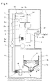
Fig. 1 is a sectional view of a water dispenser according to an embodiment of the present invention as seen from the lateral side. -
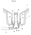
Fig. 2 is a sectional view of a main portion of the water dispenser according to the embodiment of the present invention. -
Fig. 3 is a sectional view of the water dispenser with a large amount of water remaining in a raw water container. -
Fig. 4 is a sectional view of the water dispenser with a small amount of water remaining in the raw water container. -
Fig. 5 is a sectional view of the water dispenser with no water remaining in the raw water container. -
Fig. 6 is a sectional view of the water dispenser illustrating a sterilization operation mode. -
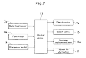
Fig. 7 is a block diagram of the water dispenser according to the embodiment of the present invention. -
Fig. 8 is a flow chart illustrating how control is performed by a control device. -
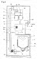
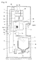
Fig. 9 is a sectional view of a water dispenser according to another embodiment of the present invention as seen from the lateral side. -
Fig. 10 is a sectional view of a water dispenser according to another embodiment of the present invention as seen from the lateral side. - The embodiments of the present invention are now described with reference to the drawings. The water dispenser according to the embodiment illustrated in
Figs. 1 and2 includes acasing 1, acold water tank 2 and ahot water tank 3 which are arranged inside of thecasing 1, aholder 5 for holding a replaceableraw water container 4, a rawwater supply line 6 through which the interior of thecold water tank 2 communicates with the interior of theraw water container 4 held by theholder 5, and apump 7 attached to the rawwater supply line 6. - The water dispenser further includes a
joint member 8 provided at the bottom end of the rawwater supply line 6 and having a built-in ultraviolet ray-emitting device 8d, acirculation line 9 branching off from the rawwater supply line 6 at two points, upper andlower switch valves 10 provided at the respective branch points at which thecirculation line 9 branches off from the rawwater supply line 6, and aheater 11 for sterilization. - The
raw water container 4 is held by thecontainer holder 5 with amouth portion 4a of thecontainer 4 directed downwardly, i.e., in the upside down position. Theraw water container 4 has atrunk portion 4b flexibly formed such that thecontainer 4 shrinks up to a predetermined limit as the amount of water remaining in thecontainer 4 decreases. Theraw water container 4 may be formed by blow molding of, for example, polyethylene terephthalate (PET) resin or polyethylene (PE) resin. The maximum volume of theraw water container 4, i.e. the maximum amount of drinking water thecontainer 4 can hold, is about 8 to 20 liters. - A
cap 4c having a built-invalve 4d is attached to an opening of themouth portion 4a of theraw water container 4. In a normal state, the opening of themouth portion 4a is closed by thisvalve 4d, thereby preventing drinking water from leaking out of theraw water container 4. - In order to make it possible to easily replace the
raw water container 4, theholder 5, arranged in the lower portion of thecasing 1, is attached to a slide table 1a provided in the lower portion of thecasing 1 and supported so as to be slidable in a horizontal direction, thereby making it possible to move theholder 5 into and out of thecasing 1 through the front side of thecasing 1. - As illustrated in
Fig. 2 , thejoint member 8 is water-tightly fixed to the bottom portion of thecontainer holder 5 through aseal member 5a so as to be removably inserted into themouth portion 4a of theraw water container 4 with thecontainer 4 held by theholder 5. - The
joint member 8 includes a tubularhollow insertion portion 8a extending in the vertical direction and having an opening at its bottom portion on which aflange 8f is provided, and a dish-shaped base portion 8b having a top opening. By overlapping theflange 8f provided on the bottom portion of theinsertion portion 8a and the open top portion of thebase portion 8b, and joining them together by an appropriate means, such as by threaded engagement, theinsertion portion 8a and thebase portion 8b are made integral with each other such that an internal space through which water can flow is defined in thejoint member 8. - As illustrated in
Fig. 2 , when theinsertion portion 8a of thejoint member 8 is inserted into themouth portion 4a of theraw water container 4, thevalve 4d of thecap 4c is fitted onto the distal end of theinsertion portion 8a, and is pushed into theraw water container 4. As a result thereof, as illustrated by the arrow inFig. 2 , drinking water contained in theraw water container 4 can flow into the internal space of thejoint member 8 from the opening of themouth portion 4a throughpassage holes 8c formed in theinsertion portion 8a. - A substantially
cylindrical mounting portion 8g is provided at the bottom center of the internal space of thejoint member 8, namely, at the bottom center of thebase portion 8b. Themounting portion 8g has the ultraviolet ray-emitting device 8d mounted thereon which is configured to emit ultraviolet rays, and which may comprise an LED light, etc. Waterproof treatment is appropriately performed to the ultraviolet ray-emittingdevice 8d, for example, by filling a gap between thedevice 8d and the mountingportion 8g of thebase portion 8b with resin. When the ultraviolet ray-emittingdevice 8d starts to operate, the internal space of thejoint member 8 is sterilized by ultraviolet rays thedevice 8d emits. - A pipe-shaped
connection port 8e is provided at the bottom portion of thebase portion 8b in the vicinity of the ultraviolet ray-emittingdevice 8d, and the rawwater supply line 6 is connected at its end on the side of the raw water container 4 (bottom end) to theconnection port 8e. As a result thereof, drinking water that has flowed into the internal space of thejoint member 8 through thepassage hole 8c can further flow into the rawwater supply line 6 through theconnection port 8e. - The
pump 7 and aflow sensor 6a are attached to the middle portion of the rawwater supply line 6 extending in the vertical direction. Thepump 7 may be, for example, a gear pump in which a pair of gears meshing with each other rotate so as to pump out drinking water. When thepump 7 is activated, drinking water in the rawwater supply line 6 is transferred upwardly from the side of theraw water container 4 toward thecold water tank 2. While thepump 7 is operating, when the rawwater supply line 6 has reached the state in which no drinking water is flowing in theline 6, theflow sensor 6a can detect this state. - The
cold water tank 2, arranged at a higher level than theholder 5 in the interior of thecasing 1, has a cooler 2a attached thereto which cools drinking water stored in thetank 2. Also, thecold water tank 2 is provided in the interior thereof with abaffle plate 2b which is arranged substantially in the horizontal direction and which partitions the internal space of thetank 2 into upper and lower portions. The cooler 2a is arranged on the outer periphery of the lower portion of thecold water tank 2, and keeps drinking water stored in thetank 2 under thebaffle plate 2b at a low temperature (about 5 degrees Celsius). - The
cold water tank 2 has awater level sensor 2c attached thereto which detects the water level of drinking water stored in thetank 2. When thewater level sensor 2c detects that the water level of drinking water has fallen, thepump 7 is activated so that drinking water is supplied from theraw water container 4 to thecold water tank 2, according to how much the water level of drinking water has fallen. - When drinking water is supplied from the
raw water container 4 to thecold water tank 2, thebaffle plate 2b prevents low-temperature drinking water cooled by the cooler 2a and stored in the lower portion of thetank 2 from mixing with and being stirred by normal-temperature drinking water supplied from thecontainer 4 to thetank 2. - The
cold water tank 2 is provided in the top surface thereof with anair intake port 2d. Air is introduced into thecold water tank 2 through theair intake port 2d according to how much the water level of drinking water has fallen in thetank 2, so that the interior of thetank 2 is maintained at atmospheric pressure. A filter, an ozone sterilization device, or an ultraviolet ray sterilization device may be attached to theair intake port 2d so that air introduced into thecold water tank 2 is kept hygienic. - The raw
water supply line 6 is connected at its end on the side of the cold water tank 2 (top end) to the upper portion of thetank 2. Right under this connection portion, thecold water tank 2 is provided with a substantially horizontally extending diffusingplate 2e configured to diffuse the flow of drinking water supplied through the rawwater supply line 6 to thecold water tank 2 before the supplied water reaches the surface of drinking water which has been already stored in thetank 2. - The
cold water tank 2 has a coldwater discharge line 2f of which one end portion (inner end portion) is connected to the bottom of thetank 2 and through which low-temperature drinking water stored in the bottom portion of thetank 2 is discharged outside. The coldwater discharge line 2f is provided at the other end portion (outer end portion) thereof with acold water cock 2g which is arranged on the front side of thecasing 1 and which is operable from the outside of thecasing 1. By opening thecold water cock 2g, low-temperature drinking water can be discharged from thecold water tank 2 into a cup, etc. The volume of thecold water tank 2 is smaller than the volume of theraw water container 4, and is about 2 to 4 liters. - A
tank connection line 12 which extends in the vertical direction and through which thecold water tank 2 and thehot water tank 3 are connected together has a top end opening at the center of thebaffle plate 2b. Through thetank connection line 12, drinking water is introduced from thecold water tank 2 into thehot water tank 3. A check valve may be mounted inside of thetank connection line 12 so as to prevent drinking water from flowing into thecold water tank 2 from thehot water tank 3. - The
hot water tank 3, arranged at a higher level than theholder 5 and at a lower level than thecold water tank 2 in the interior of thecasing 1, has aheater 3a attached to the internal space thereof which heats drinking water stored in thetank 3 and keeps it at a high temperature (about 90 degrees Celsius). - Since the
tank connection line 12 has a bottom end opening at a position lower than theheater 3a in thehot water tank 3, cooled drinking water introduced into thehot water tank 3 from thecold water tank 2 is heated by theheater 3a, and the heated water rises in thetank 3. - The
hot water tank 3 has a hotwater discharge line 3b of which one end portion (inner end portion) is connected to the top of thetank 3 and through which, when thetank 3 is substantially filled with drinking water, high-temperature drinking water stored in the upper portion of thetank 3 is discharged outside. The hotwater discharge line 3b is provided at the other end portion (outer end portion) thereof with ahot water cock 3c which is arranged on the front side of thecasing 1 and which is operable from the outside of thecasing 1. By opening thishot water cock 3c, high-temperature drinking water can be discharged from thehot water tank 3 into a cup, etc. When drinking water is discharged from thehot water tank 3, since drinking water equal in amount to the discharged drinking water flows through thetank connection line 12 into thehot water tank 3 from thecold water tank 2, thetank 3 is always filled with drinking water. The volume of thehot water tank 3 is smaller than the volume of theraw water container 4, and is about 1 to 2 liters. - The
circulation line 9 is connected at its top and bottom ends to the rawwater supply line 6 in the vicinity of thecold water tank 2 and in the vicinity of theholder 5, respectively. Namely, said upper and lower connection portions are upper and lower branch points at which thecirculation line 9 branches off from the rawwater supply line 6. - It is not necessarily required that the upper and lower branch points be located at the positions specifically illustrated in the figures, as long as the upper and lower branch points are considered to be located "in the vicinity of" the
cold water tank 2 and theholder 5, respectively, within the usual meaning of this term. For example, the upper branch point may be located such that the distance from the top end of the raw water supply line 6 (end of theline 6 on the side of the cold water tank 2) is 1/8 or less of the entire length of theline 6, and the lower branch point may be located such that the distance from the bottom end of the line 6 (end of theline 6 on the side of the holder 5) is 1/8 or less of the entire length of theline 6. - In order to allow for the slide operation of the slide table 1a by which the
holder 5 is supported, it is preferable that the rawwater supply line 6 and thecirculation line 9 are each made of a flexible material. For example, the rawwater supply line 6 and thecirculation line 9 may be each a silicon tube, a fluororesin tube, or a fluororubber tube. - When the water dispenser is in use, the flow of drinking water can be switched by the
switch valves 10, provided at the upper and lower branch points, respectively, at which thecirculation line 9 branches off from the rawwater supply line 6. - Namely, the upper and
lower switch valves 10 can switch the flow of drinking water by moving, in synchronization with each other, between a normal operation position ("off" mode) in which, as illustrated inFig. 1 , theraw water container 4, the rawwater supply line 6, and thecold water tank 2 communicate with each other, while thecirculation line 9 is disconnected from the rawwater supply line 6, and a sterilization operation position ("on" mode) in which, as illustrated inFig. 6 , both theraw water container 4 and thecold water tank 2 are disconnected from the rawwater supply line 6, with thecirculation line 9 communicating with the rawwater supply line 6. - The upper and
lower switch valves 10 shown are each constituted by a single valve. However, instead ofsuch valves 10, switch valve assemblies may be used each constituted by a plurality of valves and having the same function as theupper switch valve 10 or thelower switch valve 10. - The
heater 11 for sterilization is attached to the rawwater supply line 6. Theheater 11 is configured to be turned on and generate heat when theswitch valves 10 are in the sterilization operation position ("on" mode), and to be turned off and stop generating heat when theswitch valves 10 are in the normal operation position ("off" mode). In the figures, theheater 11 for sterilization is attached to the portion of the rawwater supply line 6 in the vicinity of the lower branch point and between the upper and lower branch points. However, theheater 11 for sterilization may be attached to any portion of the rawwater supply line 6 or of thecirculation line 9. - The
pump 7, theswitch valves 10, and theheater 11 for sterilization are controlled by acontrol device 13 illustrated inFig. 7 . A signal indicating the water level of drinking water stored in thecold water tank 2 is input to thecontrol device 13 from thewater level sensor 2c, a signal indicating the amount of drinking water flowing in the rawwater supply line 6 is input to thedevice 13 from theflow sensor 6a, and a signal is input to thedevice 13 from achangeover switch 14. - The
changeover switch 14 is manually operated to move theswitch valves 10 between the normal operation position ("off" mode) and the sterilization operation position ("on" mode), and is arranged at the front of thecasing 1. When thechangeover switch 14 is off, theswitch valves 10 and theheater 11 for sterilization are in the respective "off" modes. When thechangeover switch 14 is on, theswitch valves 10 and theheater 11 for sterilization are in the respective "on" modes. - Control signals are output from the
control device 13 to anelectric motor 7a configured to drive thepump 7, to theswitch valves 10, to theheater 11 for sterilization, and to acontainer replacement lamp 13a. - The
container replacement lamp 13a is a lamp for informing the user that theraw water container 4 is empty now, and is arranged at the front of thecasing 1. - The water dispenser according to the embodiment is configured as described above. It is now described with reference to
Fig. 8 andFigs. 1 ,3-6 how control is performed by thecontrol device 13 of this water dispenser. - First, when the
changeover switch 14 is turned off (step S1), thecontrol device 13 turns off theswitch valves 10 and theheater 11 for sterilization (step S2). - In this state, the upper and
lower switch valves 10 allow communication between theraw water container 4 and thecold water tank 2 through the rawwater supply line 6, while disconnecting the rawwater supply line 6 from thecirculation line 9, and theheater 11 for sterilization is not operating. - Second, in the state in which the
pump 7 is not operating (step S3), when thewater level sensor 2c detects that the water level of drinking water in thecold water tank 2 has fallen below a predetermined lower limit (step S4), thecontrol device 13 activates thepump 7, so that drinking water is supplied by thepump 7 from theraw water container 4 to the cold water tank 2 (step S5). - In the state in which the
pump 7 is operating (step S3), when thewater level sensor 2c detects that the water level of drinking water in thecold water tank 2 has exceeded a predetermined upper limit(step S6), thecontrol device 13 stops the operation of the pump 7 (step S7). - While, as illustrated in
Fig. 3 , a large amount of water remains in thecontainer 4, as drinking water in theraw water container 4 is drawn up by thepump 7 and supplied to thecold water 2, thecontainer 4 shrinks due to atmospheric pressure. - On the other hand, as illustrated in
Fig. 4 , when the amount of water remaining in theraw water container 4 decreases to a certain level, thecontainer 4 is shrunk to such an extent that thecontainer 4 is less likely to shrink further due to increased rigidity. - In the state in which the
pump 7 is operating (step S3), when theflow sensor 6a detects that no drinking water is flowing in the raw water supply line 6 (step S8), as illustrated inFig. 5 , little drinking water is deemed to remain in theraw water container 4. Therefore, thecontrol device 13 turns on thecontainer replacement lamp 13a (step S9), and stops the operation of thepump 7 after a predetermined period of time has passed (step S10). - On the other hand, when the
changeover switch 14 is turned on (step S1), thecontrol device 13 turns on theswitch valves 10 and theheater 11 for sterilization (step S11). - Namely at this time, communication is allowed between the raw
water supply line 6 and thecirculation line 9 by the upper andlower switch valves 10, while being blocked between theraw water container 4, the rawwater supply line 6 and thecold water tank 2 by thevalves 10, and theheater 11 for sterilization generates heat. - With the
pump 7 operating (step S12), as illustrated inFig. 6 , water remaining in the rawwater supply line 6 flows upwardly, flows into thecirculation line 9 through theupper switch valve 10, flows downwardly in thiscirculation line 9 due to thepump 7, and flows into theline 6 again through thelower switch valve 10. In this way, water circulates between the rawwater supply line 6 and thecirculation line 9. - When water circulates between the raw
water supply line 6 and thecirculation line 9, the water is heated by theheater 11 for sterilization so as to reach sterilization temperature, i.e., temperature enough to kill normal germs (about 90 degrees Celsius). As a result thereof, the rawwater supply line 6 is sterilized by hot water circulating in theline 6. - Also in this embodiment, the
heater 11 for sterilization is arranged in the lower portion of the rawwater supply line 6 in which water always remains, thus preventing theheater 11 from heating a portion of theline 6 where there is no water. Furthermore, since the upper and lower branch points at which thecirculation line 9 branches off from the rawwater supply line 6 are provided in the vicinity of thecold water tank 2 and theholder 5, respectively, hot water circulates in the substantially entire area of theline 6, thereby making it possible to sterilize a large area of theline 6. - In addition, since the interior of the
joint member 8 and the portion of the rawwater supply line 6 between the lower branch point and thejoint member 8 are sterilized by the ultraviolet ray-emittingdevice 8d, mounted inside of thejoint member 8, it is also possible to keep hygienic the portion of theline 6 in which hot water does not circulate. The ultraviolet ray-emittingdevice 8d may be always being turned on, or may be selectively turned on or turned off in synchronization with "on"/"off" mode of theheater 11 for sterilization. - While the
switch valves 10 are in the sterilization operation position, thepump 7 and theheater 11 for sterilization may be stopped, after a predetermined period of time has passed by which time sufficient sterilization effect has been obtained. - On the other hand, when the
pump 7 is not operating (step S12), thecontrol device 13 activates the pump 7 (step S13), so that the rawwater supply line 6 is sterilized by hot water in the same way as described above. -
Fig. 9 illustrates a water dispenser according to another embodiment. - In this embodiment, the middle portion of the
circulation line 9 is interrupted by thehot water tank 3. Namely, thecirculation line 9 is divided into upper and lower half portions, and the bottom end of the upper half portion and the top end of the lower half portion are connected to thehot water tank 3. - In order to sterilize the raw
water supply line 6 by hot water, thechangeover switch 14 is turned on so as to move the upper andlower switch valves 10 to the sterilization operation position, and hot water stored in thehot water tank 3 and heated by theheater 3a is circulated by thepump 7 between thecirculation line 9 and the rawwater supply line 6. - Since the
heater 3a for heating drinking water stored in thehot water tank 3 is also used as theheater 11 for sterilization in this way, it is not necessary to separately provide a heater for sterilization, and to control the heater for sterilization in synchronization with theswitch valves 10. Therefore, it is possible to simplify the structure of the water dispenser. - In
Fig. 9 , thehot water tank 3 has a substantially columnar shape in its entirety as in general hot water tanks, and as for the outer surface of thetank 3, thetank 3 has disk-shaped top and bottom surfaces and a cylindrical circumferential surface. Also, the bottom end of the upper half portion of thecirculation line 9 is connected to the bottom surface of thetank 3, and the top end of the lower half portion of theline 9 is connected to the top surface of thetank 3. - Therefore, hot water stored in the upper portion of the
hot water tank 3 and having the highest temperature is sent by thepump 7 through the lower half portion of thecirculation line 9 to the rawwater supply line 6, water of which the temperature has fallen during its circulation returns through the upper half portion of theline 9 to the lower portion of thetank 3, and the water is heated again by theheater 3a so as to go up in thetank 3 and then sent to theline 9 again. Therefore, it is possible to keep high the temperature of hot water during its circulation. - Also, since the top and bottom surfaces of the
hot water tank 3, to which thecirculation line 9 is connected, are flat surfaces, thecirculation line 9 can be easily connected to such top and bottom surfaces by e.g. welding, compared to connecting theline 9 to curved surfaces of thetank 3, to which it is more difficult to connect theline 9 by e.g. welding. By connecting thecirculation line 9 to such flat top and bottom surfaces, it is also possible to reduce the possibility of leakage of water out of the portions of thetank 3 to which theline 9 is connected, due to poor connection. -
Fig. 10 illustrates a water dispenser according to another embodiment. - Though this embodiment is the same as the embodiment illustrated in
Fig. 9 in that the middle portion of thecirculation line 9 is interrupted by thehot water tank 3, and in that theline 9 is divided into upper and lower half portions, this embodiment is different from the embodiment illustrated inFig. 9 in that the end portions of theline 9 are not directly connected to thetank 3. - Namely, the bottom end of the upper half portion of the
circulation line 9 is connected to an intermediate portion of adrain discharge line 3d substantially horizontally extending from the bottom surface of thehot water tank 3 to the back side of thecasing 1, and the top end of the lower half portion of theline 9 is connected to an intermediate portion of the hotwater discharge line 3b, extending from the top surface of thetank 3 to the front side of thecasing 1. - The
drain discharge line 3d is a line provided for substantially completely discharging water remaining in the hot water tank 3 (drain) so as to make thetank 3 empty, when the water dispenser is not in use, for example, when the water dispenser is transported or stored. - This
drain discharge line 3d is configured to be opened and closed by a known valve, etc. When the water dispenser is in use as described above, thedrain discharge line 3d is closed by a valve, etc. and not used. - Since the hot
water discharge line 3b is connected to the top surface of thehot water tank 3, only when thetank 3 is substantially filled with water, it is possible to discharge water stored in thetank 3 to the outside of thecasing 1 through theline 3b. Therefore, when the water dispenser is not in use, it is impossible to use the hotwater discharge line 3b so as to make thehot water tank 3 empty. However, in such a case, by opening thedrain discharge line 3d, connected to the bottom surface of thehot water tank 3, by a valve, etc., substantially all water stored in thetank 3 is discharged from the bottom of thetank 3 to the outside of thecasing 1 through theline 3d, thereby making it possible to make thetank 3 empty. - Needless to say, it is preferable to provide the
drain discharge line 3d in each of the embodiments illustrated inFigs. 1-8 andFig. 9 as well. However, thedrain discharge line 3d is not illustrated in these embodiments for convenience of explanation. - In order to sterilize the raw
water supply line 6 by hot water, the upper andlower switch valves 10 are each moved to the sterilization operation position, and hot water stored in thehot water tank 3 and heated by theheater 3a is introduced through the hotwater discharge line 3b into the lower half portion of thecirculation line 9 which branches off from theline 3b, and further introduced from the lower half portion of theline 9 into the rawwater supply line 6 through theswitch valve 10 arranged at the lower branch point. Thereafter, hot water flowing upwardly in the rawwater supply line 6 is introduced into the upper half portion of thecirculation line 9 through theswitch valve 10 arranged at the upper branch point, and returned from the upper half portion of theline 9 to thehot water tank 3 through thedrain discharge line 3d. - In this way, hot water circulates between the
circulation line 9 and the rawwater supply line 6 through thehot water tank 3, the hotwater discharge line 3b, and thedrain discharge line 3d. - In the embodiment illustrated in
Fig.10 , the bottom end of the upper half portion and the top end of the lower half portion of thecirculation line 9 are connected to thedrain discharge line 3d, extending from thehot water tank 3, and to the hotwater discharge line 3b, respectively. Therefore, compared to directly connecting said bottom and top ends of thecirculation line 9 to thehot water tank 3, the number of portions of thetank 3 to which respective lines are connected is small. - Namely, when the bottom end of the upper half portion and the top end of the lower half portion of the
circulation line 9 are directly connected to thehot water tank 3, the number of the portions of thetank 3 to which respective lines are connected is five. Specifically, said bottom and top ends of theline 9, the hotwater discharge line 3b, thedrain discharge line 3d, and thetank connection line 12 are connected to thetank 3. On the other hand, in the embodiment illustrated inFig. 10 , the number of portions of thehot water tank 3 to which respective lines are connected is only three. Specifically, only the hotwater discharge line 3b, thedrain discharge line 3d, and thetank connection line 12 are connected to thetank 3. - The leakage of water is likely to occur due to poor welding, etc. at the portions of the
hot water tank 3 to which respective lines are connected. Therefore, by reducing the number of portions of thehot water tank 3 to which respective lines are connected as described above, it is possible to reduce the likelihood that the leakage of water would occur. - The embodiments described herein are illustrative in all respects and not limitative. The scope of the present invention is indicated by the appended claims, and includes all modifications and variations within the scope of the claims and the meaning equivalent to the scope of the claims.
- For example, though each of the above-described embodiments illustrates the
raw water container 4, formed so as to shrink up to a predetermined limit as the amount of water remaining in thecontainer 4 decreases, the present invention may be applied to a water dispenser including a rigid raw water container (so-called "hard bottle type") of which the trunk portion does not shrink as the amount of water remaining in the container decreases. Such a rigid raw water container may be formed by blow molding of, for example, polyethylene terephthalate (PET) resin or polycarbonate (PC) resin. - Also, the present invention may be applied to a water dispenser including a raw water container flexibly formed so as to substantially shrink up to the limit as the amount of water remaining in the container decreases, so-called "bag type", or including a raw water container constituted by a bag and a box in which the bag is received, so-called "bag-in box type".
- Furthermore, though each of the above-described embodiments illustrates only the state in which the
raw water container 4 is held by theholder 5 with themouth portion 4a of thecontainer 4 directed downwardly, the present invention may be applied to a water dispenser in which theraw water container 4 is held by theholder 5 with themouth portion 4a of thecontainer 4 directed upwardly or in a lateral direction. - Also, the
holder 5 is not limited to the structure illustrated in the figures, and it is sufficient that theholder 5 can hold theraw water container 4 in any manner, for example, by placing, supporting, or storing thecontainer 4. -
- 1:
- casing
- 1a:
- sliding member
- 2:
- cold water tank
- 2a:
- cooler
- 2b:
- baffle plate
- 2c:
- water level sensor
- 2d:
- air intake
- 2e:
- diffusing plate
- 2f:
- cold water discharge line
- 2g:
- cold water cock
- 3:
- hot water tank
- 3a:
- heater
- 3b:
- hot water discharge line
- 3c:
- hot water cock
- 3d:
- drain discharge line
- 4:
- raw water container
- 4a:
- mouth portion
- 4b:
- trunk portion
- 4c:
- cap
- 4d:
- valve
- 5:
- holder
- 5a:
- seal member
- 6:
- raw water supply line
- 6a:
- flow sensor
- 7:
- pump
- 7a:
- electric motor
- 8:
- joint member
- 8a:
- insertion portion
- 8b:
- base portion
- 8c:
- passage hole
- 8d:
- ultraviolet ray-emitting device
- 8e:
- connection portion
- 8f:
- flange
- 8g:
- mounting portion
- 9:
- circulation line
- 10:
- switch valve
- 11
- heater for sterilization
- 12:
- tank connection line
- 13:
- control device
- 13a:
- container replacement lamp
- 14:
- changeover switch
Claims (5)
- A water dispenser comprising:a holder (5) configured to hold a replaceable raw water container (4) filled with drinking water and including a mouth portion (4a);;a cold water tank (2) which is arranged at a higher level than the holder (5), and in which drinking water is cooled;a raw water supply line (6) extending between the holder (5) and the cold water tank (2) and including a tubular joint member (8) provided at a bottom end portion of the raw water supply line (6), and configured to be inserted into the mouth portion 4a of the raw water container (4) with the raw water container (4) held by the holder (5) such that an interior of the cold water tank (2) communicates with an interior of the raw water container (4) through the raw water supply line (6);a pump (7) attached to the raw water supply line (6);a circulation line (9) having a top end portion connected to an upper branch point of the raw water supply line (6) in a vicinity of the cold water tank (2), and a bottom end portion connected to a lower branch point of the raw water supply line (6) in a vicinity of the holder (5);upper and lower switch valves (10) provided at the upper and lower branch points, respectively, and movable between a normal operation position in which the raw water container (4) and the cold water tank (2) communicate with the raw water supply line (6), while the raw water supply line (6) and the circulation line (9) are disconnected from each other, and a sterilization operation position in which the raw water supply line (6) communicates with the circulation line (9), while the raw water container (4) and the cold water tank (2) are disconnected from the raw water supply line (6); anda heater (11) for sterilization configured to heat water circulated by the pump (7) between the raw water supply line (6) and the circulation line (9) until the water reaches a sterilization temperature, when the upper and lower valves (10) are in the sterilization operation position.
- The water dispenser according to claim 1, further comprising a hot water tank (3) which is arranged at a higher level than the holder (5) and at a lower level than the cold water tank (2), and to which a heater (3a) is attached which heats drinking water supplied from the cold water tank (2),
wherein the circulation line (9) is interrupted by the hot water tank (3), and
wherein the heater (3a) attached to the hot water tank (3) is used as the heater (11) for sterilization. - The water dispenser according to claim 2, further comprising:a hot water discharge line (3b) extending from a top portion of the hot water tank (3), and arranged such that only when the hot water tank (3) is filled with water, water can be discharged from the hot water tank (3) through the hot water discharge line (3b); anda drain discharge line (3d) extending from a bottom portion of the hot water tank (3), and configured to be opened and closed such that when the drain discharge line (3d) is opened, drinking water in the hot water tank (3) can be completely discharged through the drain discharge line (3d);wherein the circulation line (9) is divided into an upper half portion and a lower half portion, andwherein a bottom end of the upper half portion is connected to the drain discharge line (3d), and a top end of the lower half portion is connected to the hot water discharge line (3b).
- The water dispenser according to claim 1, further comprising a hot water tank (3) which is arranged at a higher level than the holder (5) and at a lower level than the cold water tank (2), and to which a heater (3a) is attached which heats drinking water supplied from the cold water tank (2),
wherein the circulation line (9) is not connected to the hot water tank (3),
wherein the heater (11) for sterilization is provided separately from the heater (3a) attached to the hot water tank (3) at a portion of the raw water supply line (6) between the upper and lower branch points or at a portion of the circulation line (9) between the upper and lower branch points,
wherein the heater (11) for sterilization is configured to generate heat when the upper and lower switch valves (10) are in the sterilization operation position, and stop generating heat when the upper and lower switch valves (10) are in the normal operation position. - The water dispenser according to any of claims 1 to 4, further comprising an ultraviolet ray-emitting device (8d) configured to apply an ultraviolet ray to an interior of the joint member (8a) of the raw water supply line (6) so as to obtain sterilization effect.
Applications Claiming Priority (2)
| Application Number | Priority Date | Filing Date | Title |
|---|---|---|---|
| JP2012235455A JP5529237B2 (en) | 2012-10-25 | 2012-10-25 | Water server |
| PCT/JP2013/076337 WO2014065078A1 (en) | 2012-10-25 | 2013-09-27 | Water server |
Publications (2)
| Publication Number | Publication Date |
|---|---|
| EP2913295A1 true EP2913295A1 (en) | 2015-09-02 |
| EP2913295A4 EP2913295A4 (en) | 2016-06-01 |
Family
ID=50544458
Family Applications (1)
| Application Number | Title | Priority Date | Filing Date |
|---|---|---|---|
| EP13848654.3A Withdrawn EP2913295A4 (en) | 2012-10-25 | 2013-09-27 | Water server |
Country Status (7)
| Country | Link |
|---|---|
| US (1) | US20150298958A1 (en) |
| EP (1) | EP2913295A4 (en) |
| JP (1) | JP5529237B2 (en) |
| KR (1) | KR102068864B1 (en) |
| CN (1) | CN104755413B (en) |
| TW (1) | TWI591012B (en) |
| WO (1) | WO2014065078A1 (en) |
Cited By (2)
| Publication number | Priority date | Publication date | Assignee | Title |
|---|---|---|---|---|
| ITUA20163118A1 (en) * | 2016-05-03 | 2017-11-03 | Water Time Il Boccione S R L | AUTOMATIC DISTRIBUTOR OF BEVERAGES EXPRESSED WITH PAYMENT |
| EP4112535A1 (en) * | 2021-06-28 | 2023-01-04 | Scandinavian Innovation Group Oy | Cold and hot drinking water dispenser with disinfecting circuit |
Families Citing this family (12)
| Publication number | Priority date | Publication date | Assignee | Title |
|---|---|---|---|---|
| JP6552854B2 (en) * | 2015-03-23 | 2019-07-31 | プレミアムウォーター株式会社 | Beverage server |
| JP2016199300A (en) * | 2015-04-13 | 2016-12-01 | 株式会社ウォーターダイレクト | Drink server |
| US20160362287A1 (en) * | 2015-06-09 | 2016-12-15 | George Yui | Top-loading bottled water dispensers with hot water sanitizing features |
| US20160362285A1 (en) * | 2015-06-09 | 2016-12-15 | George Yui | Bottom-loading bottled water dispensers with hot water sanitizing features |
| JP6727808B2 (en) * | 2016-01-05 | 2020-07-22 | サントリーホールディングス株式会社 | Beverage supply device |
| CN106388613B (en) * | 2016-06-27 | 2023-07-07 | 苏州华爱电子有限公司 | Heating disinfection waterway system of water bottle underlying type water dispenser |
| KR20180066579A (en) * | 2016-12-09 | 2018-06-19 | 엘지전자 주식회사 | Drinking water supplying device and Controlling method for the same |
| BR112019027577B1 (en) * | 2017-06-26 | 2023-10-17 | Freezio Ag | DEVICE FOR PRODUCING A DRINK |
| CN108204381B (en) * | 2017-11-21 | 2019-05-21 | 深圳市百福康环保科技有限公司 | A kind of barreled drinking water water pumping device |
| CN107890286A (en) * | 2017-12-21 | 2018-04-10 | 广东德新科技孵化器有限公司 | A kind of water dispenser with air purification function |
| CN108820653A (en) * | 2018-06-02 | 2018-11-16 | 扬州金威环保科技有限公司 | A kind of self-tipping type garbage compression vehicle |
| CN110104601A (en) * | 2019-05-29 | 2019-08-09 | 广州巨米智能设备有限公司 | A kind of beverage output device and beverage output method |
Family Cites Families (23)
| Publication number | Priority date | Publication date | Assignee | Title |
|---|---|---|---|---|
| JPS482299Y1 (en) | 1970-03-29 | 1973-01-20 | ||
| US4544084A (en) * | 1981-12-03 | 1985-10-01 | Cleland Robert K | Beverage dispenser |
| US4958747A (en) * | 1988-08-15 | 1990-09-25 | Sheets Kerney T | Bottled water dispenser |
| JP3746605B2 (en) * | 1997-12-26 | 2006-02-15 | 富士電機リテイルシステムズ株式会社 | Drinking water dispenser |
| FR2785601B1 (en) * | 1998-11-09 | 2001-06-08 | Dieau | AUTONOMOUS DISPENSER BY GRAVITY OF FRESH DRINK IN A CUP FROM A CANDY BOTTLE WITH PERCUTABLE ORIFICE |
| JP2001153523A (en) * | 1999-11-19 | 2001-06-08 | Kyushu Kaihatsu Kikaku:Kk | Drink water heater and drink water cooler and drink water heater/cooler |
| FR2830005B1 (en) * | 2001-09-27 | 2004-07-23 | Dieau | SYSTEM FOR DISINFECTING A WATER FOUNTAIN BY FULL HEATING, METHOD, DEVICE AND FOUNTAINS THEREOF |
| NZ526987A (en) * | 2001-12-11 | 2004-11-26 | Banpo Marketing Co | Bottled water discharging apparatus |
| JP2004206301A (en) * | 2002-12-24 | 2004-07-22 | Benten:Kk | Bactericidal device of absorbed chiller heater |
| JP4549068B2 (en) * | 2004-01-19 | 2010-09-22 | サントリーホールディングス株式会社 | Drinking water dispenser |
| US7114637B2 (en) * | 2004-04-21 | 2006-10-03 | Davis Kenneth A | Method and apparatus for programably treating water in a water cooler |
| CN2920112Y (en) * | 2006-07-03 | 2007-07-11 | 于乔治 | Bottled water drinker with hot-water sterilizing system |
| US20080054017A1 (en) * | 2006-08-30 | 2008-03-06 | Mtn Products, Inc. | Liquid Dispensing Apparatus and System |
| ES2276638B1 (en) * | 2006-11-29 | 2008-06-01 | Canaletas S.A. | WATER DISPENSING SOURCE AND METHOD FOR THE HYGIENIZATION OF THIS SOURCE. |
| KR100843313B1 (en) * | 2007-11-13 | 2008-07-03 | 주식회사 동양일렉트로닉스 | Circulation type water purifier |
| CN201281521Y (en) * | 2008-07-29 | 2009-07-29 | 钱瑞林 | Cold and heat type drinking machine for automatic cycle degerming |
| JP5120428B2 (en) * | 2010-08-24 | 2013-01-16 | 富士電機リテイルシステムズ株式会社 | Drinking water supply device |
| JP5839224B2 (en) * | 2010-08-25 | 2016-01-06 | Cbcエスト株式会社 | Water server |
| JP4802299B1 (en) | 2011-04-12 | 2011-10-26 | 株式会社オーケンウォーター | Water server for easy replacement of water bottles |
| CN202426308U (en) * | 2012-01-17 | 2012-09-12 | 宁波澳成电器制造有限公司 | Water dispenser cold bravery disinfection system |
| US20130272923A1 (en) * | 2012-04-12 | 2013-10-17 | Mtn Products, Inc. | Liquid dispenser with ozonating, recirculating and improved temperature control functions |
| JP5529227B2 (en) * | 2012-09-18 | 2014-06-25 | 株式会社コスモライフ | Water server |
| JP5529233B2 (en) * | 2012-10-19 | 2014-06-25 | 株式会社コスモライフ | Water server |
-
2012
- 2012-10-25 JP JP2012235455A patent/JP5529237B2/en active Active
-
2013
- 2013-09-27 US US14/437,840 patent/US20150298958A1/en not_active Abandoned
- 2013-09-27 EP EP13848654.3A patent/EP2913295A4/en not_active Withdrawn
- 2013-09-27 WO PCT/JP2013/076337 patent/WO2014065078A1/en active Application Filing
- 2013-09-27 CN CN201380055902.9A patent/CN104755413B/en active Active
- 2013-09-27 KR KR1020157013303A patent/KR102068864B1/en active IP Right Grant
- 2013-10-17 TW TW102137571A patent/TWI591012B/en active
Cited By (3)
| Publication number | Priority date | Publication date | Assignee | Title |
|---|---|---|---|---|
| ITUA20163118A1 (en) * | 2016-05-03 | 2017-11-03 | Water Time Il Boccione S R L | AUTOMATIC DISTRIBUTOR OF BEVERAGES EXPRESSED WITH PAYMENT |
| EP4112535A1 (en) * | 2021-06-28 | 2023-01-04 | Scandinavian Innovation Group Oy | Cold and hot drinking water dispenser with disinfecting circuit |
| WO2023275719A1 (en) * | 2021-06-28 | 2023-01-05 | Scandinavian Innovation Group Oy | Cold and hot drinking water dispenser with disinfecting circuit |
Also Published As
| Publication number | Publication date |
|---|---|
| TW201425201A (en) | 2014-07-01 |
| EP2913295A4 (en) | 2016-06-01 |
| CN104755413A (en) | 2015-07-01 |
| TWI591012B (en) | 2017-07-11 |
| WO2014065078A1 (en) | 2014-05-01 |
| KR102068864B1 (en) | 2020-01-21 |
| JP5529237B2 (en) | 2014-06-25 |
| US20150298958A1 (en) | 2015-10-22 |
| CN104755413B (en) | 2017-03-08 |
| KR20150077463A (en) | 2015-07-07 |
| JP2014084155A (en) | 2014-05-12 |
Similar Documents
| Publication | Publication Date | Title |
|---|---|---|
| EP2913295A1 (en) | Water server | |
| TWI624631B (en) | Water server | |
| KR102065202B1 (en) | Water server | |
| JP2005207604A (en) | Drinking water dispenser | |
| JP5520403B1 (en) | Water server | |
| TW201437560A (en) | Water server | |
| JP2014201322A (en) | Water server | |
| KR102090854B1 (en) | Water server | |
| CN104203803A (en) | Water dispenser | |
| EP2980012A1 (en) | Water server | |
| ES2735953T3 (en) | Apparatus and procedure for preparing a beverage from a liquid supplied to a container, by means of a machine | |
| JP5520404B1 (en) | Water server | |
| EP3801440B1 (en) | System for administering and heating liquids | |
| JP2015100509A (en) | Disinfection device | |
| CN114072353A (en) | Beverage machine | |
| KR101351180B1 (en) | Drink vending machine having sterilization device | |
| JP2013224163A (en) | Water server |
Legal Events
| Date | Code | Title | Description |
|---|---|---|---|
| PUAI | Public reference made under article 153(3) epc to a published international application that has entered the european phase |
Free format text: ORIGINAL CODE: 0009012 |
|
| 17P | Request for examination filed |
Effective date: 20150522 |
|
| AK | Designated contracting states |
Kind code of ref document: A1 Designated state(s): AL AT BE BG CH CY CZ DE DK EE ES FI FR GB GR HR HU IE IS IT LI LT LU LV MC MK MT NL NO PL PT RO RS SE SI SK SM TR |
|
| AX | Request for extension of the european patent |
Extension state: BA ME |
|
| DAX | Request for extension of the european patent (deleted) | ||
| RA4 | Supplementary search report drawn up and despatched (corrected) |
Effective date: 20160503 |
|
| RIC1 | Information provided on ipc code assigned before grant |
Ipc: B67D 1/08 20060101AFI20160426BHEP Ipc: B67D 1/07 20060101ALI20160426BHEP Ipc: B67D 3/00 20060101ALI20160426BHEP Ipc: B67D 1/00 20060101ALI20160426BHEP Ipc: B67D 1/10 20060101ALI20160426BHEP |
|
| STAA | Information on the status of an ep patent application or granted ep patent |
Free format text: STATUS: THE APPLICATION HAS BEEN WITHDRAWN |
|
| 18W | Application withdrawn |
Effective date: 20160906 |