EP2913222A1 - Child safety seat - Google Patents
Child safety seat Download PDFInfo
- Publication number
- EP2913222A1 EP2913222A1 EP14001741.9A EP14001741A EP2913222A1 EP 2913222 A1 EP2913222 A1 EP 2913222A1 EP 14001741 A EP14001741 A EP 14001741A EP 2913222 A1 EP2913222 A1 EP 2913222A1
- Authority
- EP
- European Patent Office
- Prior art keywords
- headrest
- actuator
- axle
- adjusting mechanism
- component
- Prior art date
- Legal status (The legal status is an assumption and is not a legal conclusion. Google has not performed a legal analysis and makes no representation as to the accuracy of the status listed.)
- Granted
Links
Images




Classifications
-
- B—PERFORMING OPERATIONS; TRANSPORTING
- B60—VEHICLES IN GENERAL
- B60N—SEATS SPECIALLY ADAPTED FOR VEHICLES; VEHICLE PASSENGER ACCOMMODATION NOT OTHERWISE PROVIDED FOR
- B60N2/00—Seats specially adapted for vehicles; Arrangement or mounting of seats in vehicles
- B60N2/24—Seats specially adapted for vehicles; Arrangement or mounting of seats in vehicles for particular purposes or particular vehicles
- B60N2/26—Seats specially adapted for vehicles; Arrangement or mounting of seats in vehicles for particular purposes or particular vehicles for children
-
- B—PERFORMING OPERATIONS; TRANSPORTING
- B60—VEHICLES IN GENERAL
- B60N—SEATS SPECIALLY ADAPTED FOR VEHICLES; VEHICLE PASSENGER ACCOMMODATION NOT OTHERWISE PROVIDED FOR
- B60N2/00—Seats specially adapted for vehicles; Arrangement or mounting of seats in vehicles
- B60N2/24—Seats specially adapted for vehicles; Arrangement or mounting of seats in vehicles for particular purposes or particular vehicles
- B60N2/26—Seats specially adapted for vehicles; Arrangement or mounting of seats in vehicles for particular purposes or particular vehicles for children
- B60N2/28—Seats readily mountable on, and dismountable from, existing seats or other parts of the vehicle
- B60N2/2851—Seats readily mountable on, and dismountable from, existing seats or other parts of the vehicle provided with head-rests
-
- B—PERFORMING OPERATIONS; TRANSPORTING
- B60—VEHICLES IN GENERAL
- B60N—SEATS SPECIALLY ADAPTED FOR VEHICLES; VEHICLE PASSENGER ACCOMMODATION NOT OTHERWISE PROVIDED FOR
- B60N2/00—Seats specially adapted for vehicles; Arrangement or mounting of seats in vehicles
- B60N2/80—Head-rests
- B60N2/806—Head-rests movable or adjustable
- B60N2/809—Head-rests movable or adjustable vertically slidable
-
- B—PERFORMING OPERATIONS; TRANSPORTING
- B60—VEHICLES IN GENERAL
- B60N—SEATS SPECIALLY ADAPTED FOR VEHICLES; VEHICLE PASSENGER ACCOMMODATION NOT OTHERWISE PROVIDED FOR
- B60N2/00—Seats specially adapted for vehicles; Arrangement or mounting of seats in vehicles
- B60N2/80—Head-rests
- B60N2/806—Head-rests movable or adjustable
- B60N2/809—Head-rests movable or adjustable vertically slidable
- B60N2/812—Head-rests movable or adjustable vertically slidable characterised by their locking devices
- B60N2/815—Release mechanisms, e.g. buttons
-
- B—PERFORMING OPERATIONS; TRANSPORTING
- B60—VEHICLES IN GENERAL
- B60N—SEATS SPECIALLY ADAPTED FOR VEHICLES; VEHICLE PASSENGER ACCOMMODATION NOT OTHERWISE PROVIDED FOR
- B60N2/00—Seats specially adapted for vehicles; Arrangement or mounting of seats in vehicles
- B60N2/80—Head-rests
- B60N2/806—Head-rests movable or adjustable
- B60N2/809—Head-rests movable or adjustable vertically slidable
- B60N2/812—Head-rests movable or adjustable vertically slidable characterised by their locking devices
- B60N2/818—Head-rests movable or adjustable vertically slidable characterised by their locking devices with stepwise positioning
Definitions
- the present invention relates to an adjusting mechanism for a height adjustable headrest of a child safety seat and to a child safety seat comprising such an adjusting mechanism.
- Child safety seats are employed for the safe transport of children in vehicles. Many of these child safety seats comprise a headrest which is intended to protect the child's head. To achieve a high level of protection it is important that the headrest is suitably positioned in the child safety seat with respect to the child's head. Since a child safety seat is usually used over a period of several months or years, during which period a child will experience significant growth, it has become common practice to provide a child safety seat with a height adjustable headrest. In such a child safety seat the height of the headrest can be adjusted to the needs of a specific child.
- the present invention is directed to an adjusting mechanism for a height adjustable headrest of a child safety seat, the child safety seat comprising a seat shell and a headrest, wherein the headrest is slidably mounted to the seat shell for up-and-down movement.
- the adjusting mechanism in accordance with the invention comprises an actuator and a locking device, wherein the locking device is configured to releasably lock the headrest at a selected height, wherein the actuator is configured to allow the locking device to be released by actuation of the actuator, thus allowing the height of the headrest to be adjusted, and wherein the actuator is positioned between the headrest and the seat shell and is configured to project above the headrest.
- the headrest When the locking device is locked, the headrest is fixed at a specific height or position. In order to adjust the height of the headrest, i.e. to slide the headrest to another position, the locking device has to be unlocked. This can be achieved by actuating the actuator. As soon as the locking device is released or unlocked, the headrest can be repositioned. By positioning the actuator between the headrest and the seat shell and by having the actuator project above the headrest it can be ensured that the actuator is always easily accessible. Since the actuator is positioned between the headrest and the seat shell, the actuator is positioned in front of the seat shell, not behind the seat shell.
- the adjusting mechanism is operable from the front of the child safety seat and is operable with one hand.
- the locking device comprises a first component mounted to the seat shell and a second component mounted to the headrest, wherein the second component is configured to releasably engage with the first component.
- the first component may be formed integrally with the seat shell. This might reduce manufacturing costs of a child safety seat comprising an adjusting mechanism in accordance with the invention.
- the first component comprises a toothed rack and the second component comprises a locking lever and an axle, wherein the locking lever is pivotally mounted to the headrest and the axle is adapted to be disengaged from the toothed rack by pivoting of the locking lever in order to unlock the locking device.
- the locking lever is pivotally mounted to the headrest and the axle is adapted to be disengaged from the toothed rack by pivoting of the locking lever in order to unlock the locking device.
- the locking device is locked.
- the locking device can be unlocked by pivoting the locking lever so that the axle is disengaged from the toothed rack.
- the headrest is locked in a specific position by inserting the axle in the recess of the toothed rack corresponding to this specific position.
- the configuration of the toothed rack e.g., number of teeth/recesses, size of teeth/distance between adjacent recesses
- the possible positions of the headrest can be configured.
- the actuator is coupled to the locking lever such that by pushing the actuator downwards the locking lever is configured to pivot in order to disengage the axle from the toothed rack.
- the locking device can be released.
- the headrest can be repositioned. To lower the headrest, it is sufficient to continue pushing the actuator downwards. Therefore, with this configuration of the adjusting mechanism of the invention, lowering the headrest of the child safety seat is a very straightforward and intuitive process: pushing the actuator downwards is all one needs to do in order to lower the headrest.
- the teeth of the toothed rack are shaped to allow the axle to automatically snap from one position to another position when the actuator or the headrest is being pulled upwards.
- a shape is advantageous since with this shape of the teeth, in order to raise the headrest, it will not be necessary to release the locking device by pushing the actuator downwards. Instead, the locking device will be automatically released as the headrest or the actuator is being pulled upwards.
- raising the headrest of the child safety seat will also be intuitive: the headrest can be raised simply by pulling the actuator or the headrest upwards. There is no need to separately release or unlock the locking device.
- the adjusting mechanism of the invention furthermore comprises a biasing member configured to bias the axle into engagement with the toothed rack.
- a biasing member configured to bias the axle into engagement with the toothed rack.
- the toothed rack is shaped so that the axle is prevented from being forced out of a recess positioned between two adjacent teeth of the toothed rack by pushing the headrest downwards, whereas the axle is free to slide out of the recess when the headrest is being pulled upwards.
- the actuator has to be actuated so that the locking device gets released, i.e. the axle is disengaged from the toothed rack, whereas in order to raise the headrest, there is no need to release the locking device by actuating the actuator. Instead, the locking device will be automatically released as the headrest is being raised.
- the headrest may be lowered or raised in a very convenient way.
- a child safety seat comprising the adjusting mechanism described above.
- the child safety seat furthermore comprises an internal harness system comprising shoulder straps, wherein the shoulder straps are routed over the axle.
- an internal harness system comprising shoulder straps, wherein the shoulder straps are routed over the axle.
- the adjusting mechanism of the invention is designed to allow the mechanism to be operable from the front of the child safety seat, to be operable with one hand, to be intuitive for a user, and to be running smoothly.
- an adjusting mechanism for a height adjustable headrest of a child safety seat comprising a seat shell, a headrest, an actuator, and a locking device, wherein the headrest is slidably mounted to the seat shell for up-and-down movement, the locking device is configured to releasably lock the headrest at a selected height, and the actuator is configured to allow the locking device to be released by actuation of the actuator, thus allowing the height of the headrest to be adjusted.
- an adjusting mechanism for a height adjustable headrest of a child safety seat comprising a seat shell and a headrest, wherein the headrest is slidably mounted to the seat shell for up-and-down movement, the adjusting mechanism comprising an actuator and a locking device, wherein the locking device is configured to releasably lock the headrest at a selected height, and wherein the actuator is configured to allow the locking device to be released by actuation of the actuator, thus allowing the height of the headrest to be adjusted, wherein the locking device comprises a locking lever which is pivotally mounted to the headrest and an axle which is connected to the locking lever, wherein the locking device furthermore comprises a toothed rack which is mounted to the seat shell and wherein the axle is configured to releasably engage with the toothed rack in order to releasably lock the headrest, wherein the axle is adapted to be disengaged from the toothed rack by pivoting of the locking lever in response to
- Fig. 1 shows a child safety seat comprising an adjusting mechanism for a height adjustable headrest 1 in accordance with an embodiment of the invention.
- the child safety seat comprises a seat shell 2, a height adjustable headrest 1, an actuator 3, and a locking device 4.
- the headrest 1 is slidably mounted to the seat shell 2 for up-and-down movement.
- the seat shell 2 comprises a backrest portion and a seating portion.
- the headrest 1 is coupled to the backrest portion of the seat shell 2.
- the adjusting mechanism furthermore comprises a locking device 4.
- the locking device 4 is configured to releasably lock the position of the headrest 1.
- the locking device 4 comprises a first component 5 and a second component 6.
- the first component 5 comprises a toothed rack 7 which is fixedly mounted to the back of the backrest portion of the seat shell 2.
- the toothed rack 7 is integrally formed with the seat shell 2.
- the second component 6 of the locking device 4 comprises a locking lever 8 and an axle 9.
- the locking lever 8 is pivotally mounted to the headrest 1 by two pins 12 and is configured to pivot about the pivot axis defined by the pins 12.
- the axle 9 is fixedly mounted to the locking lever 8 and is adapted to engage with the toothed rack 7 in order to lock the headrest 1 in a selected position. To unlock the headrest 1, the axle 9 is disengaged from the toothed rack 7. This is achieved by pivoting the locking lever 8 about the pivot axis.
- the adjusting mechanism shown in Fig. 1 furthermore comprises a biasing member in the form of a spring 11.
- This spring 11 is coupled to the locking lever 8 and to the headrest 1.
- the spring 11 forces the axle 9 into engagement with the toothed rack 7 as will become more apparent in subsequent Figures.
- the adjusting mechanism furthermore comprises an actuator 3 which is positioned between the headrest 1 and the seat shell 2 and which is configured to project above the headrest 1.
- the actuator 3 is configured to allow the locking device 4 to be released by actuation of the actuator 3.
- the adjusting mechanism furthermore comprises a cover 13 which is configured to partly cover the locking lever 8 and which is mounted to the headrest 1 by two screws 14. Furthermore, the cover 13 is configured to prevent the headrest 1 from being detached from the child safety seat.
- Fig. 2 shows a rear view of the child safety seat of Fig. 1 .
- the axle 9 engages with the toothed rack 7, thus locking the headrest 1 in the uppermost position.
- the actuator 3 is configured to project above the headrest 1. Therefore, the actuator can be easily reached by a user of the child safety seat, even from the front of the seat.
- Fig. 3a is a sectional view of the child safety seat of Figs. 1 and 2 .
- the height adjustable headrest 1 is locked in the uppermost position. Again, the actuator 3 can be seen to project above the headrest 1.
- the tension spring 11 is coupled to the locking lever 8 and to the headrest 1 and is configured to generate a torque to pivot the locking lever 8 about the pivot axis defined by the pins 12 in the clockwise direction. Since the axle 9 is coupled to the locking lever 8 below the pins 12, this torque forces the axle 9 into engagement with the toothed rack 7. To release the locking device 4 of the adjusting mechanism in accordance with the invention, the actuator 3 is pushed downwards.
- FIG. 3b This is shown in Fig. 3b .
- the actuator 3 has been pushed downwards in the direction indicated by arrow 16.
- the actuator 3 When the actuator 3 is pushed downwards, it generates another torque on the locking lever 8 which counteracts the torque generated by the spring 11. If the torque generated by the actuator 3 exceeds the torque generated by the spring 11, the locking lever 8 will be pivoted about the pivot axis defined by the pins 12 in the counterclockwise direction, thus removing the axle 9 from the toothed rack 7 in the direction indicated by arrow 17.
- the actuator 3 down will first release the locking device 4 and will then push the headrest 1 down to a lower position.
- Fig. 4a shows the headrest 1 locked in the lowered position of Fig. 3d .
- the actuator 3 can be pulled upwards in the direction indicated by arrow 20 in Fig. 4b , or the headrest 1 itself can be pulled upwards in the direction indicated by arrow 19 in Fig. 4b .
- the actuator 3 is coupled to the headrest 1 in such a way that by pulling the actuator 3 upwards, the actuator 3 loses contact with the locking lever 8.
- the locking lever 8 which is coupled to the headrest 1 will also be pulled upwards.
- the teeth 10 of the toothed rack 7 are shaped such that when the locking lever 8 is pulled upwards, the axle 9 is pushed out of the recess between two teeth by sliding on the edge of the tooth positioned above the axle 9.
- the locking lever 8 continues to pivot about the pins 12 in the direction indicated by arrow 17 until the axle 9 has reached the top of a tooth of the toothed rack 7.
- the axle 9 will snap into the next recess positioned between two teeth of the toothed rack 7, thus locking the headrest in a raised position.
- Fig. 5a shows the toothed rack 7 of an adjusting mechanism in accordance with the invention in more detail.
- the toothed rack 7 comprises a plurality of teeth 10. Each pair of adjacent teeth 10 defines a recess 10a positioned between these teeth 10.
- the recesses 10a are configured to receive the axle 9.
- the locking lever 8 is configured to pivot about the pivot axis defined by the pins 12. In the configuration shown in Fig. 5a the headrest 1 is locked since the axle 9 engages with the toothed rack 7. In particular, the axle 9 is positioned in a recess 10a.
- the headrest 1 cannot be lowered simply by pushing the headrest 1 downwards in the direction indicated by arrow 15.
- Fig. 5b is similar to Fig. 5a but shows in addition a strap of a harness 22.
- This harness strap 22 may be a shoulder belt of the internal harness system of a child safety seat in accordance with the invention.
- the harness strap 22 is routed over the axle 9.
- a force is exerted on the harness strap 22 in the direction of arrow 23 (e.g. in the course of an accident)
- the axle 9 will receive a force acting in the direction of arrow 24. This force will press the axle 9 further into the recess 10a, thus safely locking the headrest 1 in the selected position.
Landscapes
- Engineering & Computer Science (AREA)
- Aviation & Aerospace Engineering (AREA)
- Transportation (AREA)
- Mechanical Engineering (AREA)
- Health & Medical Sciences (AREA)
- Child & Adolescent Psychology (AREA)
- General Health & Medical Sciences (AREA)
- Seats For Vehicles (AREA)
Abstract
Description
- The present invention relates to an adjusting mechanism for a height adjustable headrest of a child safety seat and to a child safety seat comprising such an adjusting mechanism.
- Child safety seats are employed for the safe transport of children in vehicles. Many of these child safety seats comprise a headrest which is intended to protect the child's head. To achieve a high level of protection it is important that the headrest is suitably positioned in the child safety seat with respect to the child's head. Since a child safety seat is usually used over a period of several months or years, during which period a child will experience significant growth, it has become common practice to provide a child safety seat with a height adjustable headrest. In such a child safety seat the height of the headrest can be adjusted to the needs of a specific child.
- Since the headrest of a child safety seat has a significant influence on the level of protection the child safety seat is able to provide, it is obvious that there is a need for a reliable and easily operated adjusting mechanism for the headrest of a child safety seat. Parents and other caregivers may be reluctant to constantly adjust the headrest to the proper height if the mechanism is complicated to operate or if there could be doubts as to whether the headrest has been properly secured in the new position.
- Therefore, it is an object of the present invention to provide a reliable adjusting mechanism for a height adjustable headrest of a child safety seat which is easily operated.
- This object is solved by the adjusting mechanism in accordance with the present invention with the features of
claim 1. Advantageous embodiments of the present invention are indicated in dependent claims 2-10. - The present invention is directed to an adjusting mechanism for a height adjustable headrest of a child safety seat, the child safety seat comprising a seat shell and a headrest, wherein the headrest is slidably mounted to the seat shell for up-and-down movement. The adjusting mechanism in accordance with the invention comprises an actuator and a locking device, wherein the locking device is configured to releasably lock the headrest at a selected height, wherein the actuator is configured to allow the locking device to be released by actuation of the actuator, thus allowing the height of the headrest to be adjusted, and wherein the actuator is positioned between the headrest and the seat shell and is configured to project above the headrest.
- When the locking device is locked, the headrest is fixed at a specific height or position. In order to adjust the height of the headrest, i.e. to slide the headrest to another position, the locking device has to be unlocked. This can be achieved by actuating the actuator. As soon as the locking device is released or unlocked, the headrest can be repositioned. By positioning the actuator between the headrest and the seat shell and by having the actuator project above the headrest it can be ensured that the actuator is always easily accessible. Since the actuator is positioned between the headrest and the seat shell, the actuator is positioned in front of the seat shell, not behind the seat shell. Therefore, with this actuator, there is no need to reach to the back of the child safety seat (as with actuators that are positioned on the back of the backrest of the child safety seat) in order to adjust the headrest. Furthermore, since the actuator projects above the headrest, there is no need to have access to the possibly narrow space between headrest and seat shell in order to reach the actuator. As a result, the adjusting mechanism is operable from the front of the child safety seat and is operable with one hand.
- Advantageously, the locking device comprises a first component mounted to the seat shell and a second component mounted to the headrest, wherein the second component is configured to releasably engage with the first component. With these two components, one being mounted to the seat shell, the other one being mounted to the headrest, the headrest's position relative to the seat shell can be reliably locked. Since the second component is configured to releasably engage with the first component, the headrest's position will not be permanently locked. Instead, the locking can be released by disengaging the second component from the first component.
- Instead of being mounted to the seat shell, the first component may be formed integrally with the seat shell. This might reduce manufacturing costs of a child safety seat comprising an adjusting mechanism in accordance with the invention.
- Preferably, the first component comprises a toothed rack and the second component comprises a locking lever and an axle, wherein the locking lever is pivotally mounted to the headrest and the axle is adapted to be disengaged from the toothed rack by pivoting of the locking lever in order to unlock the locking device. When the axle engages with the toothed rack, the locking device is locked. The locking device can be unlocked by pivoting the locking lever so that the axle is disengaged from the toothed rack. By making use of a toothed rack a number of locking positions can be defined for the headrest. Each recess positioned between two adjacent teeth of the toothed rack corresponds to one possible position of the headrest. The headrest is locked in a specific position by inserting the axle in the recess of the toothed rack corresponding to this specific position. By adjusting the configuration of the toothed rack (e.g., number of teeth/recesses, size of teeth/distance between adjacent recesses) the possible positions of the headrest can be configured.
- Advantageously, the actuator is coupled to the locking lever such that by pushing the actuator downwards the locking lever is configured to pivot in order to disengage the axle from the toothed rack. Thus, by pushing the actuator downwards, the locking device can be released. As soon as the locking device is released, the headrest can be repositioned. To lower the headrest, it is sufficient to continue pushing the actuator downwards. Therefore, with this configuration of the adjusting mechanism of the invention, lowering the headrest of the child safety seat is a very straightforward and intuitive process: pushing the actuator downwards is all one needs to do in order to lower the headrest.
- Advantageously, the teeth of the toothed rack are shaped to allow the axle to automatically snap from one position to another position when the actuator or the headrest is being pulled upwards. To give the teeth of the toothed rack such a shape is advantageous since with this shape of the teeth, in order to raise the headrest, it will not be necessary to release the locking device by pushing the actuator downwards. Instead, the locking device will be automatically released as the headrest or the actuator is being pulled upwards. Thus, raising the headrest of the child safety seat will also be intuitive: the headrest can be raised simply by pulling the actuator or the headrest upwards. There is no need to separately release or unlock the locking device.
- Advantageously, the adjusting mechanism of the invention furthermore comprises a biasing member configured to bias the axle into engagement with the toothed rack. With this biasing member it can be ensured that in the rest configuration of the adjusting mechanism, i.e. without actuation of the actuator, the locking device is locked. In the rest configuration the axle is held in engagement with the toothed rack by the biasing member. To disengage the axle from the toothed rack, i.e. to unlock the locking device, the biasing force exerted on the axle by the biasing member has to be overcome.
- Advantageously, the toothed rack is shaped so that the axle is prevented from being forced out of a recess positioned between two adjacent teeth of the toothed rack by pushing the headrest downwards, whereas the axle is free to slide out of the recess when the headrest is being pulled upwards. This ensures that in order to lower the headrest, the actuator has to be actuated so that the locking device gets released, i.e. the axle is disengaged from the toothed rack, whereas in order to raise the headrest, there is no need to release the locking device by actuating the actuator. Instead, the locking device will be automatically released as the headrest is being raised. Thus, the headrest may be lowered or raised in a very convenient way.
- According to another aspect of the invention, there is provided a child safety seat comprising the adjusting mechanism described above.
- Advantageously, the child safety seat furthermore comprises an internal harness system comprising shoulder straps, wherein the shoulder straps are routed over the axle. By routing the shoulder straps over the axle, forces acting on the shoulder straps during a crash of the vehicle carrying the child safety seat can be employed to further secure the position of the headrest of the child safety seat. The shoulder straps can be made to press the axle to the toothed rack, thus preventing the axle from disengaging from the toothed rack.
- Overall, the adjusting mechanism of the invention is designed to allow the mechanism to be operable from the front of the child safety seat, to be operable with one hand, to be intuitive for a user, and to be running smoothly.
- According to another aspect of the invention an adjusting mechanism for a height adjustable headrest of a child safety seat is provided, the child safety seat comprising a seat shell, a headrest, an actuator, and a locking device, wherein the headrest is slidably mounted to the seat shell for up-and-down movement, the locking device is configured to releasably lock the headrest at a selected height, and the actuator is configured to allow the locking device to be released by actuation of the actuator, thus allowing the height of the headrest to be adjusted.
- According to another aspect of the invention an adjusting mechanism for a height adjustable headrest of a child safety seat is provided, the child safety seat comprising a seat shell and a headrest, wherein the headrest is slidably mounted to the seat shell for up-and-down movement, the adjusting mechanism comprising an actuator and a locking device, wherein the locking device is configured to releasably lock the headrest at a selected height, and wherein the actuator is configured to allow the locking device to be released by actuation of the actuator, thus allowing the height of the headrest to be adjusted, wherein the locking device comprises a locking lever which is pivotally mounted to the headrest and an axle which is connected to the locking lever, wherein the locking device furthermore comprises a toothed rack which is mounted to the seat shell and wherein the axle is configured to releasably engage with the toothed rack in order to releasably lock the headrest, wherein the axle is adapted to be disengaged from the toothed rack by pivoting of the locking lever in response to a downward force acting on the actuator in order to unlock the locking device.
- Specific embodiments of the invention will now be described by way of example and with reference to the accompanying drawings, in which:
-
Fig. 1 is an exploded view of a child safety seat comprising an adjusting mechanism for a height adjustable headrest in accordance with an embodiment of the invention; -
Fig. 2 is a rear view of the child safety seat ofFig. 1 ; -
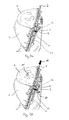
Fig. 3a is a sectional view of the child safety seat ofFig. 1 , with the height adjustable headrest locked in the uppermost position; -
Fig. 3b is a sectional view similar toFig. 3a , with the height adjustable headrest unlocked for adjustment of its height; -
Fig. 3c is a sectional view similar toFig. 3b , with the height adjustable headrest pushed to a lower position; -
Fig. 3d is a sectional view similar toFig. 3c , with the height adjustable headrest locked in a lower position; -
Fig. 4a is a sectional view similar toFig. 3d , with the height adjustable headrest locked in a lower position; -
Fig. 4b is a sectional view similar toFig. 4a , with the height adjustable headrest slightly raised from the position ofFig. 4a , thereby unlocking a locking device; -
Fig. 4c is a sectional view similar toFig. 4b , with the height adjustable headrest raised higher, the locking device still unlocked; -
Fig. 4d is a sectional view similar toFig. 4c , with the height adjustable headrest locked again in the uppermost position; -
Fig. 5a is a detailed view of the adjusting mechanism of the previous Figures; and -
Fig. 5b is another detailed view of the same adjusting mechanism. -
Fig. 1 shows a child safety seat comprising an adjusting mechanism for a heightadjustable headrest 1 in accordance with an embodiment of the invention. The child safety seat comprises aseat shell 2, a heightadjustable headrest 1, anactuator 3, and alocking device 4. Theheadrest 1 is slidably mounted to theseat shell 2 for up-and-down movement. Theseat shell 2 comprises a backrest portion and a seating portion. Theheadrest 1 is coupled to the backrest portion of theseat shell 2. The adjusting mechanism furthermore comprises alocking device 4. Thelocking device 4 is configured to releasably lock the position of theheadrest 1. - The
locking device 4 comprises a first component 5 and a second component 6. In the embodiment of the invention shown inFig. 1 the first component 5 comprises a toothed rack 7 which is fixedly mounted to the back of the backrest portion of theseat shell 2. In an alternative embodiment of the invention, the toothed rack 7 is integrally formed with theseat shell 2. The second component 6 of thelocking device 4 comprises a lockinglever 8 and anaxle 9. The lockinglever 8 is pivotally mounted to theheadrest 1 by twopins 12 and is configured to pivot about the pivot axis defined by thepins 12. Theaxle 9 is fixedly mounted to the lockinglever 8 and is adapted to engage with the toothed rack 7 in order to lock theheadrest 1 in a selected position. To unlock theheadrest 1, theaxle 9 is disengaged from the toothed rack 7. This is achieved by pivoting the lockinglever 8 about the pivot axis. - The adjusting mechanism shown in
Fig. 1 furthermore comprises a biasing member in the form of aspring 11. Thisspring 11 is coupled to the lockinglever 8 and to theheadrest 1. Thespring 11 forces theaxle 9 into engagement with the toothed rack 7 as will become more apparent in subsequent Figures. The adjusting mechanism furthermore comprises anactuator 3 which is positioned between theheadrest 1 and theseat shell 2 and which is configured to project above theheadrest 1. Theactuator 3 is configured to allow thelocking device 4 to be released by actuation of theactuator 3. - The adjusting mechanism furthermore comprises a
cover 13 which is configured to partly cover the lockinglever 8 and which is mounted to theheadrest 1 by twoscrews 14. Furthermore, thecover 13 is configured to prevent theheadrest 1 from being detached from the child safety seat. -
Fig. 2 shows a rear view of the child safety seat ofFig. 1 . In this view theaxle 9 engages with the toothed rack 7, thus locking theheadrest 1 in the uppermost position. As can be clearly seen in this view, theactuator 3 is configured to project above theheadrest 1. Therefore, the actuator can be easily reached by a user of the child safety seat, even from the front of the seat. - The process of lowering the
headrest 1 with the adjusting mechanism of the invention is shown inFigs. 3a-d . -
Fig. 3a is a sectional view of the child safety seat ofFigs. 1 and2 . The heightadjustable headrest 1 is locked in the uppermost position. Again, theactuator 3 can be seen to project above theheadrest 1. Thetension spring 11 is coupled to the lockinglever 8 and to theheadrest 1 and is configured to generate a torque to pivot the lockinglever 8 about the pivot axis defined by thepins 12 in the clockwise direction. Since theaxle 9 is coupled to the lockinglever 8 below thepins 12, this torque forces theaxle 9 into engagement with the toothed rack 7. To release thelocking device 4 of the adjusting mechanism in accordance with the invention, theactuator 3 is pushed downwards. - This is shown in
Fig. 3b . Here, theactuator 3 has been pushed downwards in the direction indicated byarrow 16. When theactuator 3 is pushed downwards, it generates another torque on the lockinglever 8 which counteracts the torque generated by thespring 11. If the torque generated by theactuator 3 exceeds the torque generated by thespring 11, the lockinglever 8 will be pivoted about the pivot axis defined by thepins 12 in the counterclockwise direction, thus removing theaxle 9 from the toothed rack 7 in the direction indicated byarrow 17. As soon as theaxle 9 is disengaged from the toothed rack 7, theheadrest 1 is free to move downwards in the direction indicated byarrow 15. Therefore, pushing theactuator 3 down will first release thelocking device 4 and will then push theheadrest 1 down to a lower position. - In
Fig. 3c theheadrest 1 has reached the lower position. Theaxle 9 is still disengaged from the toothed rack 7. Therefore, if thedownward force 16 on theactuator 3 would continue to be applied, theheadrest 1 would continue to be lowered in the direction indicated byarrow 15. To lock theheadrest 1 in the lowered position, theactuator 3 has to be released. When theactuator 3 is released, theactuator 3 will no longer generate a torque on the lockinglever 8. Therefore, thespring 11 will again bring theaxle 9 into engagement with the toothed rack 7, now locking the headrest in the lowered position. - This is shown in
Fig. 3d where the lockinglever 8 has been pivoted about thepins 12 in the direction indicated byarrow 18. This clockwise rotation of the lockinglever 8 brings theaxle 9 back into engagement with the toothed rack 7 and pushes theactuator 3 upwards so that theactuator 3 again projects above theheadrest 1. - The process of raising the
headrest 1 with the adjusting mechanism of the invention is shown inFigs. 4a-d . -
Fig. 4a shows theheadrest 1 locked in the lowered position ofFig. 3d . To raise theheadrest 1, theactuator 3 can be pulled upwards in the direction indicated byarrow 20 inFig. 4b , or theheadrest 1 itself can be pulled upwards in the direction indicated byarrow 19 inFig. 4b . Theactuator 3 is coupled to theheadrest 1 in such a way that by pulling theactuator 3 upwards, theactuator 3 loses contact with the lockinglever 8. When theheadrest 1 is pulled upwards, the lockinglever 8 which is coupled to theheadrest 1 will also be pulled upwards. Theteeth 10 of the toothed rack 7 are shaped such that when the lockinglever 8 is pulled upwards, theaxle 9 is pushed out of the recess between two teeth by sliding on the edge of the tooth positioned above theaxle 9. - This is shown in
Fig. 4b .Actuator 3 is pulled upwards in the direction indicated byarrow 20, thus raising theheadrest 1 in the direction indicated byarrow 19. By this, lockinglever 8 is also raised. Thus,axle 9 slides on the edge of the tooth positioned aboveaxle 9. As a result, the lockinglever 8 begins to pivot about the pivot axis defined by thepins 12 in the direction indicated byarrow 17, against the force of thetension spring 11. - When the
headrest 1 is raised further in the direction indicated byarrow 19, as shown inFig. 4c , the lockinglever 8 continues to pivot about thepins 12 in the direction indicated byarrow 17 until theaxle 9 has reached the top of a tooth of the toothed rack 7. When theheadrest 1 is then still raised further, theaxle 9 will snap into the next recess positioned between two teeth of the toothed rack 7, thus locking the headrest in a raised position. - This is shown in
Fig. 4d . The lockinglever 8 is pivoted about thepins 12 by thetension spring 11 so that theaxle 9 is brought into engagement with the toothed rack 7. Theheadrest 1 is locked again. -
Fig. 5a shows the toothed rack 7 of an adjusting mechanism in accordance with the invention in more detail. The toothed rack 7 comprises a plurality ofteeth 10. Each pair ofadjacent teeth 10 defines arecess 10a positioned between theseteeth 10. Therecesses 10a are configured to receive theaxle 9. The lockinglever 8 is configured to pivot about the pivot axis defined by thepins 12. In the configuration shown inFig. 5a theheadrest 1 is locked since theaxle 9 engages with the toothed rack 7. In particular, theaxle 9 is positioned in arecess 10a. Theheadrest 1 cannot be lowered simply by pushing theheadrest 1 downwards in the direction indicated byarrow 15. When theheadrest 1 is pushed downwards in the direction indicated byarrow 15, a force will be exerted on theaxle 9 acting in the direction indicated byarrow 15a. This is due to the fact that theaxle 9 is positioned in front of thepins 12. In other words, the pivot axis defined by thepins 12 is placed behind the toothed rack 7. Due to the specific shape of theteeth 10 of the toothed rack 7, the force acting on theaxle 9 in the direction ofarrow 15a locks theaxle 9 in therecess 10a. Thus, theheadrest 1 cannot be lowered without releasing thelocking device 4 first by actuation of theactuator 3. -
Fig. 5b is similar toFig. 5a but shows in addition a strap of aharness 22. Thisharness strap 22 may be a shoulder belt of the internal harness system of a child safety seat in accordance with the invention. Theharness strap 22 is routed over theaxle 9. When a force is exerted on theharness strap 22 in the direction of arrow 23 (e.g. in the course of an accident), theaxle 9 will receive a force acting in the direction ofarrow 24. This force will press theaxle 9 further into therecess 10a, thus safely locking theheadrest 1 in the selected position. -
- 1
- headrest
- 2
- seat shell
- 3
- actuator
- 4
- locking device
- 5
- first component of locking
device 4 - 6
- second component of locking
device 4 - 7
- toothed rack
- 8
- locking lever
- 9
- axle
- 10
- teeth of toothed rack 7
- 10a
- recess
- 11
- biasing member/tension spring
- 12
- pin
- 13
- cover
- 14
- screws
- 15
- direction of downward movement of
headrest 1 - 15a
- force on
axle 9 - 16
- direction of pushing
actuator 3 downwards - 17
- release direction of locking
lever 8 - 18
- engagement direction of locking
lever 8 - 19
- direction of upward movement of
headrest 1 - 20
- direction of pulling
actuator 3 upwards - 22
- harness strap
- 23
- pulling force on harness strap
- 24
- force on
axle 9
Claims (10)
- An adjusting mechanism for a height adjustable headrest (1) of a child safety seat, the child safety seat comprising a seat shell (2) and a headrest (1), wherein the headrest (1) is slidably mounted to the seat shell (2) for up-and-down movement,
the adjusting mechanism comprising an actuator (3) and a locking device (4), wherein the locking device (4) is configured to releasably lock the headrest (1) at a selected height,
wherein the actuator (3) is configured to allow the locking device (4) to be released by actuation of the actuator (3), thus allowing the height of the headrest (1) to be adjusted, and
wherein the actuator (3) is positioned between the headrest (1) and the seat shell (2) and is configured to project above the headrest (1). - The adjusting mechanism of claim 1, wherein the locking device (4) comprises a first component (5) mounted to the seat shell (2) and a second component (6) mounted to the headrest (1), wherein the second component (6) is configured to releasably engage with the first component (5).
- The adjusting mechanism of claim 1, wherein the locking device (4) comprises a first component (5) formed integrally with the seat shell (2) and a second component (6) mounted to the headrest (1), wherein the second component (6) is configured to releasably engage with the first component (5).
- The adjusting mechanism of claim 2 or 3, wherein the first component (5) comprises a toothed rack (7) and the second component (6) comprises a locking lever (8) and an axle (9), wherein the locking lever (8) is pivotally mounted to the headrest (1) and the axle (9) is adapted to be disengaged from the toothed rack (7) by pivoting of the locking lever (8) in order to unlock the locking device (4).
- The adjusting mechanism of claim 4, wherein the actuator (3) is coupled to the locking lever (8) such that by pushing the actuator (3) downwards the locking lever (8) is configured to pivot in order to disengage the axle (9) from the toothed rack (7).
- The adjusting mechanism of claim 4 or 5, wherein the teeth of the toothed rack (7) are shaped to allow the axle (9) to automatically snap from one position to another position when the actuator (3) or the headrest (1) is being pulled upwards.
- The adjusting mechanism of any one of claims 4 to 6, furthermore comprising a biasing member (11) configured to bias the axle (9) into engagement with the toothed rack (7).
- The adjusting mechanism of any one of claims 4 to 7, wherein the toothed rack (7) is shaped so that the axle (9) is prevented from being forced out of a recess (10a) positioned between two adjacent teeth (10) of the toothed rack (7) by pushing the headrest (1) downwards, whereas the axle (9) is free to slide out of the recess (10a) when the headrest (1) is being pulled upwards.
- A child safety seat comprising the adjusting mechanism of any one of the previous claims.
- A child safety seat comprising the adjusting mechanism of any one of claims 4 to 8, the child safety seat furthermore comprising an internal harness system comprising shoulder straps, wherein the shoulder straps are routed over the axle (9).
Priority Applications (4)
| Application Number | Priority Date | Filing Date | Title |
|---|---|---|---|
| EP14001741.9A EP2913222B1 (en) | 2014-02-28 | 2014-05-16 | Child safety seat |
| CA2881133A CA2881133C (en) | 2014-02-28 | 2015-02-05 | Child safety seat |
| US14/618,242 US9415707B2 (en) | 2014-02-28 | 2015-02-10 | Child safety seat |
| CN201510083301.XA CN104742765B (en) | 2014-02-28 | 2015-02-15 | Child safety seat |
Applications Claiming Priority (2)
| Application Number | Priority Date | Filing Date | Title |
|---|---|---|---|
| EP14000726 | 2014-02-28 | ||
| EP14001741.9A EP2913222B1 (en) | 2014-02-28 | 2014-05-16 | Child safety seat |
Publications (2)
| Publication Number | Publication Date |
|---|---|
| EP2913222A1 true EP2913222A1 (en) | 2015-09-02 |
| EP2913222B1 EP2913222B1 (en) | 2020-01-22 |
Family
ID=50193196
Family Applications (1)
| Application Number | Title | Priority Date | Filing Date |
|---|---|---|---|
| EP14001741.9A Active EP2913222B1 (en) | 2014-02-28 | 2014-05-16 | Child safety seat |
Country Status (4)
| Country | Link |
|---|---|
| US (1) | US9415707B2 (en) |
| EP (1) | EP2913222B1 (en) |
| CN (1) | CN104742765B (en) |
| CA (1) | CA2881133C (en) |
Cited By (2)
| Publication number | Priority date | Publication date | Assignee | Title |
|---|---|---|---|---|
| CN109204080A (en) * | 2018-11-15 | 2019-01-15 | 苏州因诺威汽车科技有限公司 | Head rest adjusting device for fibre reinforced composites child safety seat |
| US20220080865A1 (en) * | 2020-09-17 | 2022-03-17 | Wonderland Switzerland Ag | Child safety seat having a headrest |
Families Citing this family (28)
| Publication number | Priority date | Publication date | Assignee | Title |
|---|---|---|---|---|
| US10363951B2 (en) * | 2015-06-11 | 2019-07-30 | Safe-Strap Company, Llc | Child restraint for child seat |
| US9585483B2 (en) * | 2015-06-29 | 2017-03-07 | Yao-Chuan Wu | Adjustable head support apparatus |
| CN105774605B (en) * | 2016-03-07 | 2017-12-15 | 中山市硕森日用制品有限公司 | Automobile child safety seat |
| FR3054501B1 (en) * | 2016-07-27 | 2018-07-27 | Faurecia Sieges D'automobile | RACK AND MANUFACTURING METHOD, HEADREST INCLUDING SUCH RACK AND SEAT COMPRISING SUCH A HEADREST |
| CN107826001B (en) * | 2016-09-16 | 2020-05-22 | 明门瑞士股份有限公司 | Supporting leg and child safety seat assembly thereof |
| CN106976419B (en) * | 2017-03-12 | 2023-02-03 | 浙江乐优贝汽车用品有限公司 | Seat headrest adjustment lock mechanism |
| EP3590757B1 (en) * | 2017-09-06 | 2021-04-21 | BRITAX RÖMER Kindersicherheit GmbH | Child safety seat with headrest height adjustment mechanism |
| US10875426B2 (en) | 2017-09-26 | 2020-12-29 | Dorel Juvenile Group, Inc. | Adjustable headrest for juvenile vehicle seat |
| CN107813742B (en) * | 2017-09-27 | 2024-02-02 | 布童安全科技(宁波)有限公司 | A child safety seat and its preparation process |
| US10807506B2 (en) | 2017-12-18 | 2020-10-20 | Dorel Juvenile Group, Inc. | Child restraint with movable headrest |
| US10843605B2 (en) * | 2018-05-10 | 2020-11-24 | Dorel Juvenile Group, Inc. | Headrest-height adjuster for juvenile seat |
| CN108657033B (en) * | 2018-05-17 | 2024-03-01 | 麦克英孚(宁波)婴童用品有限公司 | A safety seat with adjustable headrest |
| CN109278600B (en) * | 2018-08-29 | 2024-05-24 | 布童安全科技(宁波)有限公司 | Self-locking headrest height adjustment mechanism |
| CN109017474B (en) * | 2018-09-04 | 2023-05-23 | 好孩子儿童用品有限公司 | A child safety seat |
| US11155187B2 (en) | 2018-09-12 | 2021-10-26 | Wonderland Switzerland Ag | Child restraint base and child restraint system |
| US10703231B1 (en) | 2019-01-23 | 2020-07-07 | Dorel Juvenile Group, Inc. | Juvenile vehicle seat with movable headrest |
| CN210047367U (en) * | 2019-06-21 | 2020-02-11 | 符锡炯 | Headrest height adjusting structure of child safety seat |
| CN110641331A (en) * | 2019-10-09 | 2020-01-03 | 浙江感恩科技股份有限公司 | Anti-drop adjusting mechanism for headrest of child safety seat |
| US11584267B2 (en) | 2020-02-05 | 2023-02-21 | Artsana Usa, Inc. | Rotatable car seat with detachable seat and top anchor |
| US12233759B2 (en) | 2020-02-05 | 2025-02-25 | Artsana Usa, Inc. | Rotatable car seat with detachable seat and top anchor |
| US12263764B2 (en) | 2020-02-05 | 2025-04-01 | Artsana Usa, Inc. | Rotatable car seat with detachable seat and top anchor |
| CN118665291A (en) * | 2020-05-29 | 2024-09-20 | 宝钜瑞士股份有限公司 | Carrier body and infant car seat |
| CN117962713A (en) * | 2020-10-13 | 2024-05-03 | 宝钜瑞士股份有限公司 | How to adjust the headrest height |
| KR20220049112A (en) * | 2020-10-14 | 2022-04-21 | 현대자동차주식회사 | Device for adjusting hight of mono-post type headrest for vehicle |
| US12030411B2 (en) | 2022-01-28 | 2024-07-09 | Britax Child Safety, Inc. | Child restraint system with posture fit mechanism |
| CN114619931B (en) * | 2022-02-28 | 2025-10-24 | 东莞恒耀日用制品有限公司 | A safety seat |
| US12576756B2 (en) | 2022-05-16 | 2026-03-17 | Dorel Juvenile Group, Inc. | Child restraint with movable headrest |
| CN120439903A (en) * | 2024-02-07 | 2025-08-08 | 明门(中国)幼童用品有限公司 | Child safety seat |
Citations (8)
| Publication number | Priority date | Publication date | Assignee | Title |
|---|---|---|---|---|
| WO2007035386A1 (en) * | 2005-09-15 | 2007-03-29 | Wonderland Nurserygoods Co., Ltd. | Adjustable head rest for child car seat |
| US20100264705A1 (en) * | 2009-04-16 | 2010-10-21 | Cosco Management, Inc. | Child vehicle seat |
| US20120153690A1 (en) * | 2010-12-21 | 2012-06-21 | Cosco Management, Inc. | Adjustable headrest for juvenile vehicle |
| US20120242127A1 (en) * | 2011-03-22 | 2012-09-27 | Cosco Management, Inc. | Adjustable headrest for juvenile vehicle seat |
| GB2491708A (en) * | 2011-06-07 | 2012-12-12 | Bp Childrens Prod Hk Co Ltd | Child safety seat with headrest and panel to cover a portion of a backrest when the headrest is adjusted |
| CN202753817U (en) * | 2012-07-06 | 2013-02-27 | 明门(中国)幼童用品有限公司 | Seat back assembly and its child safety seat |
| US20130320725A1 (en) * | 2012-05-14 | 2013-12-05 | William Elias Conway | Child Car Seat with Height Adjustable Head Rest and Adjustment Mechanism for Same |
| US20140049081A1 (en) * | 2012-08-15 | 2014-02-20 | Evenflo Company, Inc. | Adjustment mechanism for juvenile product |
Family Cites Families (3)
| Publication number | Priority date | Publication date | Assignee | Title |
|---|---|---|---|---|
| US7066536B2 (en) * | 2002-02-11 | 2006-06-27 | Graco Children's Products Inc. | Child seat |
| US8141951B2 (en) * | 2008-09-10 | 2012-03-27 | Excellerate Enterprise Co., Ltd. | Child safety seat |
| CN202173100U (en) * | 2011-05-30 | 2012-03-28 | 宝钜儿童用品香港股份有限公司 | Headrest height adjusting device |
-
2014
- 2014-05-16 EP EP14001741.9A patent/EP2913222B1/en active Active
-
2015
- 2015-02-05 CA CA2881133A patent/CA2881133C/en active Active
- 2015-02-10 US US14/618,242 patent/US9415707B2/en active Active
- 2015-02-15 CN CN201510083301.XA patent/CN104742765B/en active Active
Patent Citations (8)
| Publication number | Priority date | Publication date | Assignee | Title |
|---|---|---|---|---|
| WO2007035386A1 (en) * | 2005-09-15 | 2007-03-29 | Wonderland Nurserygoods Co., Ltd. | Adjustable head rest for child car seat |
| US20100264705A1 (en) * | 2009-04-16 | 2010-10-21 | Cosco Management, Inc. | Child vehicle seat |
| US20120153690A1 (en) * | 2010-12-21 | 2012-06-21 | Cosco Management, Inc. | Adjustable headrest for juvenile vehicle |
| US20120242127A1 (en) * | 2011-03-22 | 2012-09-27 | Cosco Management, Inc. | Adjustable headrest for juvenile vehicle seat |
| GB2491708A (en) * | 2011-06-07 | 2012-12-12 | Bp Childrens Prod Hk Co Ltd | Child safety seat with headrest and panel to cover a portion of a backrest when the headrest is adjusted |
| US20130320725A1 (en) * | 2012-05-14 | 2013-12-05 | William Elias Conway | Child Car Seat with Height Adjustable Head Rest and Adjustment Mechanism for Same |
| CN202753817U (en) * | 2012-07-06 | 2013-02-27 | 明门(中国)幼童用品有限公司 | Seat back assembly and its child safety seat |
| US20140049081A1 (en) * | 2012-08-15 | 2014-02-20 | Evenflo Company, Inc. | Adjustment mechanism for juvenile product |
Cited By (4)
| Publication number | Priority date | Publication date | Assignee | Title |
|---|---|---|---|---|
| CN109204080A (en) * | 2018-11-15 | 2019-01-15 | 苏州因诺威汽车科技有限公司 | Head rest adjusting device for fibre reinforced composites child safety seat |
| CN109204080B (en) * | 2018-11-15 | 2024-04-12 | 苏州因诺威汽车科技有限公司 | Headrest adjusting device for fiber reinforced composite child safety seat |
| US20220080865A1 (en) * | 2020-09-17 | 2022-03-17 | Wonderland Switzerland Ag | Child safety seat having a headrest |
| US11801778B2 (en) * | 2020-09-17 | 2023-10-31 | Wonderland Switzerland Ag | Child safety seat having a headrest |
Also Published As
| Publication number | Publication date |
|---|---|
| CA2881133C (en) | 2017-06-27 |
| CN104742765B (en) | 2017-09-19 |
| CN104742765A (en) | 2015-07-01 |
| US9415707B2 (en) | 2016-08-16 |
| EP2913222B1 (en) | 2020-01-22 |
| US20150246629A1 (en) | 2015-09-03 |
| CA2881133A1 (en) | 2015-08-28 |
Similar Documents
| Publication | Publication Date | Title |
|---|---|---|
| CA2881133C (en) | Child safety seat | |
| JP7360787B2 (en) | Child safety seat with headrest height adjustment mechanism | |
| US9592751B2 (en) | Child safety seat for use in a vehicle | |
| EP3378697B1 (en) | Support base for a child safety seat | |
| CN104553903B (en) | Child seat with safety belt and manufacturing method thereof | |
| EP3165400A1 (en) | Child safety seat | |
| US9119445B2 (en) | Buckle assemblies with lift latches and associated methods and systems | |
| EP2786895B1 (en) | Child safety seat | |
| US8991919B2 (en) | Child safety seat for vehicles | |
| TW202530042A (en) | Headrest height adjusting mechanism and child carrier thereof | |
| CN101573252A (en) | Device for operating the anchoring system of an infant seat for automobiles | |
| JP6463791B2 (en) | Child seat device | |
| US20160059746A1 (en) | Adjustable Foot For A Child Car Seat Base | |
| AU2024227530A1 (en) | Child restraint with harness adjustment | |
| EP3428006B1 (en) | A child vehicle seat as well as an inlay for such a child vehicle seat | |
| WO2007128548A2 (en) | Bracket system adapted for use in a raising and lowering mechanism of an adjustable headrest of a vehicle seat | |
| CN116424177A (en) | Safety seat and backrest angle adjusting mechanism thereof |
Legal Events
| Date | Code | Title | Description |
|---|---|---|---|
| PUAI | Public reference made under article 153(3) epc to a published international application that has entered the european phase |
Free format text: ORIGINAL CODE: 0009012 |
|
| AK | Designated contracting states |
Kind code of ref document: A1 Designated state(s): AL AT BE BG CH CY CZ DE DK EE ES FI FR GB GR HR HU IE IS IT LI LT LU LV MC MK MT NL NO PL PT RO RS SE SI SK SM TR |
|
| AX | Request for extension of the european patent |
Extension state: BA ME |
|
| 17P | Request for examination filed |
Effective date: 20160302 |
|
| RBV | Designated contracting states (corrected) |
Designated state(s): AL AT BE BG CH CY CZ DE DK EE ES FI FR GB GR HR HU IE IS IT LI LT LU LV MC MK MT NL NO PL PT RO RS SE SI SK SM TR |
|
| STAA | Information on the status of an ep patent application or granted ep patent |
Free format text: STATUS: EXAMINATION IS IN PROGRESS |
|
| 17Q | First examination report despatched |
Effective date: 20180426 |
|
| REG | Reference to a national code |
Ref country code: DE Ref legal event code: R079 Ref document number: 602014060235 Country of ref document: DE Free format text: PREVIOUS MAIN CLASS: B60N0002280000 Ipc: B60N0002815000 |
|
| RIC1 | Information provided on ipc code assigned before grant |
Ipc: B60N 2/28 20060101ALI20190627BHEP Ipc: B60N 2/818 20180101ALI20190627BHEP Ipc: B60N 2/815 20180101AFI20190627BHEP |
|
| GRAP | Despatch of communication of intention to grant a patent |
Free format text: ORIGINAL CODE: EPIDOSNIGR1 |
|
| STAA | Information on the status of an ep patent application or granted ep patent |
Free format text: STATUS: GRANT OF PATENT IS INTENDED |
|
| INTG | Intention to grant announced |
Effective date: 20190828 |
|
| GRAS | Grant fee paid |
Free format text: ORIGINAL CODE: EPIDOSNIGR3 |
|
| GRAA | (expected) grant |
Free format text: ORIGINAL CODE: 0009210 |
|
| STAA | Information on the status of an ep patent application or granted ep patent |
Free format text: STATUS: THE PATENT HAS BEEN GRANTED |
|
| AK | Designated contracting states |
Kind code of ref document: B1 Designated state(s): AL AT BE BG CH CY CZ DE DK EE ES FI FR GB GR HR HU IE IS IT LI LT LU LV MC MK MT NL NO PL PT RO RS SE SI SK SM TR |
|
| RAP1 | Party data changed (applicant data changed or rights of an application transferred) |
Owner name: BRITAX ROEMER KINDERSICHERHEIT GMBH |
|
| REG | Reference to a national code |
Ref country code: GB Ref legal event code: FG4D |
|
| REG | Reference to a national code |
Ref country code: CH Ref legal event code: EP |
|
| REG | Reference to a national code |
Ref country code: DE Ref legal event code: R096 Ref document number: 602014060235 Country of ref document: DE |
|
| REG | Reference to a national code |
Ref country code: AT Ref legal event code: REF Ref document number: 1226719 Country of ref document: AT Kind code of ref document: T Effective date: 20200215 |
|
| REG | Reference to a national code |
Ref country code: IE Ref legal event code: FG4D |
|
| REG | Reference to a national code |
Ref country code: NL Ref legal event code: MP Effective date: 20200122 |
|
| REG | Reference to a national code |
Ref country code: LT Ref legal event code: MG4D |
|
| PG25 | Lapsed in a contracting state [announced via postgrant information from national office to epo] |
Ref country code: NL Free format text: LAPSE BECAUSE OF FAILURE TO SUBMIT A TRANSLATION OF THE DESCRIPTION OR TO PAY THE FEE WITHIN THE PRESCRIBED TIME-LIMIT Effective date: 20200122 Ref country code: RS Free format text: LAPSE BECAUSE OF FAILURE TO SUBMIT A TRANSLATION OF THE DESCRIPTION OR TO PAY THE FEE WITHIN THE PRESCRIBED TIME-LIMIT Effective date: 20200122 Ref country code: PT Free format text: LAPSE BECAUSE OF FAILURE TO SUBMIT A TRANSLATION OF THE DESCRIPTION OR TO PAY THE FEE WITHIN THE PRESCRIBED TIME-LIMIT Effective date: 20200614 Ref country code: FI Free format text: LAPSE BECAUSE OF FAILURE TO SUBMIT A TRANSLATION OF THE DESCRIPTION OR TO PAY THE FEE WITHIN THE PRESCRIBED TIME-LIMIT Effective date: 20200122 Ref country code: NO Free format text: LAPSE BECAUSE OF FAILURE TO SUBMIT A TRANSLATION OF THE DESCRIPTION OR TO PAY THE FEE WITHIN THE PRESCRIBED TIME-LIMIT Effective date: 20200422 |
|
| PG25 | Lapsed in a contracting state [announced via postgrant information from national office to epo] |
Ref country code: GR Free format text: LAPSE BECAUSE OF FAILURE TO SUBMIT A TRANSLATION OF THE DESCRIPTION OR TO PAY THE FEE WITHIN THE PRESCRIBED TIME-LIMIT Effective date: 20200423 Ref country code: BG Free format text: LAPSE BECAUSE OF FAILURE TO SUBMIT A TRANSLATION OF THE DESCRIPTION OR TO PAY THE FEE WITHIN THE PRESCRIBED TIME-LIMIT Effective date: 20200422 Ref country code: HR Free format text: LAPSE BECAUSE OF FAILURE TO SUBMIT A TRANSLATION OF THE DESCRIPTION OR TO PAY THE FEE WITHIN THE PRESCRIBED TIME-LIMIT Effective date: 20200122 Ref country code: LV Free format text: LAPSE BECAUSE OF FAILURE TO SUBMIT A TRANSLATION OF THE DESCRIPTION OR TO PAY THE FEE WITHIN THE PRESCRIBED TIME-LIMIT Effective date: 20200122 Ref country code: IS Free format text: LAPSE BECAUSE OF FAILURE TO SUBMIT A TRANSLATION OF THE DESCRIPTION OR TO PAY THE FEE WITHIN THE PRESCRIBED TIME-LIMIT Effective date: 20200522 Ref country code: SE Free format text: LAPSE BECAUSE OF FAILURE TO SUBMIT A TRANSLATION OF THE DESCRIPTION OR TO PAY THE FEE WITHIN THE PRESCRIBED TIME-LIMIT Effective date: 20200122 |
|
| REG | Reference to a national code |
Ref country code: DE Ref legal event code: R097 Ref document number: 602014060235 Country of ref document: DE |
|
| PG25 | Lapsed in a contracting state [announced via postgrant information from national office to epo] |
Ref country code: SM Free format text: LAPSE BECAUSE OF FAILURE TO SUBMIT A TRANSLATION OF THE DESCRIPTION OR TO PAY THE FEE WITHIN THE PRESCRIBED TIME-LIMIT Effective date: 20200122 Ref country code: EE Free format text: LAPSE BECAUSE OF FAILURE TO SUBMIT A TRANSLATION OF THE DESCRIPTION OR TO PAY THE FEE WITHIN THE PRESCRIBED TIME-LIMIT Effective date: 20200122 Ref country code: SK Free format text: LAPSE BECAUSE OF FAILURE TO SUBMIT A TRANSLATION OF THE DESCRIPTION OR TO PAY THE FEE WITHIN THE PRESCRIBED TIME-LIMIT Effective date: 20200122 Ref country code: DK Free format text: LAPSE BECAUSE OF FAILURE TO SUBMIT A TRANSLATION OF THE DESCRIPTION OR TO PAY THE FEE WITHIN THE PRESCRIBED TIME-LIMIT Effective date: 20200122 Ref country code: ES Free format text: LAPSE BECAUSE OF FAILURE TO SUBMIT A TRANSLATION OF THE DESCRIPTION OR TO PAY THE FEE WITHIN THE PRESCRIBED TIME-LIMIT Effective date: 20200122 Ref country code: RO Free format text: LAPSE BECAUSE OF FAILURE TO SUBMIT A TRANSLATION OF THE DESCRIPTION OR TO PAY THE FEE WITHIN THE PRESCRIBED TIME-LIMIT Effective date: 20200122 Ref country code: CZ Free format text: LAPSE BECAUSE OF FAILURE TO SUBMIT A TRANSLATION OF THE DESCRIPTION OR TO PAY THE FEE WITHIN THE PRESCRIBED TIME-LIMIT Effective date: 20200122 Ref country code: LT Free format text: LAPSE BECAUSE OF FAILURE TO SUBMIT A TRANSLATION OF THE DESCRIPTION OR TO PAY THE FEE WITHIN THE PRESCRIBED TIME-LIMIT Effective date: 20200122 |
|
| REG | Reference to a national code |
Ref country code: AT Ref legal event code: MK05 Ref document number: 1226719 Country of ref document: AT Kind code of ref document: T Effective date: 20200122 |
|
| PLBE | No opposition filed within time limit |
Free format text: ORIGINAL CODE: 0009261 |
|
| STAA | Information on the status of an ep patent application or granted ep patent |
Free format text: STATUS: NO OPPOSITION FILED WITHIN TIME LIMIT |
|
| 26N | No opposition filed |
Effective date: 20201023 |
|
| PG25 | Lapsed in a contracting state [announced via postgrant information from national office to epo] |
Ref country code: MC Free format text: LAPSE BECAUSE OF FAILURE TO SUBMIT A TRANSLATION OF THE DESCRIPTION OR TO PAY THE FEE WITHIN THE PRESCRIBED TIME-LIMIT Effective date: 20200122 Ref country code: AT Free format text: LAPSE BECAUSE OF FAILURE TO SUBMIT A TRANSLATION OF THE DESCRIPTION OR TO PAY THE FEE WITHIN THE PRESCRIBED TIME-LIMIT Effective date: 20200122 Ref country code: IT Free format text: LAPSE BECAUSE OF FAILURE TO SUBMIT A TRANSLATION OF THE DESCRIPTION OR TO PAY THE FEE WITHIN THE PRESCRIBED TIME-LIMIT Effective date: 20200122 Ref country code: CH Free format text: LAPSE BECAUSE OF NON-PAYMENT OF DUE FEES Effective date: 20200531 Ref country code: LI Free format text: LAPSE BECAUSE OF NON-PAYMENT OF DUE FEES Effective date: 20200531 |
|
| PG25 | Lapsed in a contracting state [announced via postgrant information from national office to epo] |
Ref country code: SI Free format text: LAPSE BECAUSE OF FAILURE TO SUBMIT A TRANSLATION OF THE DESCRIPTION OR TO PAY THE FEE WITHIN THE PRESCRIBED TIME-LIMIT Effective date: 20200122 Ref country code: PL Free format text: LAPSE BECAUSE OF FAILURE TO SUBMIT A TRANSLATION OF THE DESCRIPTION OR TO PAY THE FEE WITHIN THE PRESCRIBED TIME-LIMIT Effective date: 20200122 |
|
| REG | Reference to a national code |
Ref country code: BE Ref legal event code: MM Effective date: 20200531 |
|
| PG25 | Lapsed in a contracting state [announced via postgrant information from national office to epo] |
Ref country code: LU Free format text: LAPSE BECAUSE OF NON-PAYMENT OF DUE FEES Effective date: 20200516 |
|
| PG25 | Lapsed in a contracting state [announced via postgrant information from national office to epo] |
Ref country code: IE Free format text: LAPSE BECAUSE OF NON-PAYMENT OF DUE FEES Effective date: 20200516 |
|
| PG25 | Lapsed in a contracting state [announced via postgrant information from national office to epo] |
Ref country code: BE Free format text: LAPSE BECAUSE OF NON-PAYMENT OF DUE FEES Effective date: 20200531 |
|
| PG25 | Lapsed in a contracting state [announced via postgrant information from national office to epo] |
Ref country code: TR Free format text: LAPSE BECAUSE OF FAILURE TO SUBMIT A TRANSLATION OF THE DESCRIPTION OR TO PAY THE FEE WITHIN THE PRESCRIBED TIME-LIMIT Effective date: 20200122 Ref country code: MT Free format text: LAPSE BECAUSE OF FAILURE TO SUBMIT A TRANSLATION OF THE DESCRIPTION OR TO PAY THE FEE WITHIN THE PRESCRIBED TIME-LIMIT Effective date: 20200122 Ref country code: CY Free format text: LAPSE BECAUSE OF FAILURE TO SUBMIT A TRANSLATION OF THE DESCRIPTION OR TO PAY THE FEE WITHIN THE PRESCRIBED TIME-LIMIT Effective date: 20200122 |
|
| PG25 | Lapsed in a contracting state [announced via postgrant information from national office to epo] |
Ref country code: MK Free format text: LAPSE BECAUSE OF FAILURE TO SUBMIT A TRANSLATION OF THE DESCRIPTION OR TO PAY THE FEE WITHIN THE PRESCRIBED TIME-LIMIT Effective date: 20200122 Ref country code: AL Free format text: LAPSE BECAUSE OF FAILURE TO SUBMIT A TRANSLATION OF THE DESCRIPTION OR TO PAY THE FEE WITHIN THE PRESCRIBED TIME-LIMIT Effective date: 20200122 |
|
| PGFP | Annual fee paid to national office [announced via postgrant information from national office to epo] |
Ref country code: DE Payment date: 20250519 Year of fee payment: 12 |
|
| PGFP | Annual fee paid to national office [announced via postgrant information from national office to epo] |
Ref country code: GB Payment date: 20250522 Year of fee payment: 12 |
|
| PGFP | Annual fee paid to national office [announced via postgrant information from national office to epo] |
Ref country code: FR Payment date: 20250523 Year of fee payment: 12 |