EP2913131A1 - Small-diameter drill - Google Patents
Small-diameter drill Download PDFInfo
- Publication number
- EP2913131A1 EP2913131A1 EP13848502.4A EP13848502A EP2913131A1 EP 2913131 A1 EP2913131 A1 EP 2913131A1 EP 13848502 A EP13848502 A EP 13848502A EP 2913131 A1 EP2913131 A1 EP 2913131A1
- Authority
- EP
- European Patent Office
- Prior art keywords
- cutting edge
- flute
- portion cutting
- diameter
- drill
- Prior art date
- Legal status (The legal status is an assumption and is not a legal conclusion. Google has not performed a legal analysis and makes no representation as to the accuracy of the status listed.)
- Granted
Links
- 230000003014 reinforcing effect Effects 0.000 claims description 5
- 238000003754 machining Methods 0.000 abstract description 21
- 238000012545 processing Methods 0.000 abstract description 10
- 230000002349 favourable effect Effects 0.000 abstract description 7
- 238000011156 evaluation Methods 0.000 description 6
- 230000000694 effects Effects 0.000 description 3
- 238000012360 testing method Methods 0.000 description 3
- 238000013461 design Methods 0.000 description 2
- 239000002184 metal Substances 0.000 description 2
- 238000013459 approach Methods 0.000 description 1
- 230000007423 decrease Effects 0.000 description 1
- 238000000034 method Methods 0.000 description 1
- 238000012986 modification Methods 0.000 description 1
- 230000004048 modification Effects 0.000 description 1
- 230000011218 segmentation Effects 0.000 description 1
- 229910001220 stainless steel Inorganic materials 0.000 description 1
- 239000010935 stainless steel Substances 0.000 description 1
Images

Classifications
-
- B—PERFORMING OPERATIONS; TRANSPORTING
- B23—MACHINE TOOLS; METAL-WORKING NOT OTHERWISE PROVIDED FOR
- B23B—TURNING; BORING
- B23B51/00—Tools for drilling machines
- B23B51/02—Twist drills
-
- B—PERFORMING OPERATIONS; TRANSPORTING
- B23—MACHINE TOOLS; METAL-WORKING NOT OTHERWISE PROVIDED FOR
- B23B—TURNING; BORING
- B23B51/00—Tools for drilling machines
- B23B51/06—Drills with lubricating or cooling equipment
-
- B—PERFORMING OPERATIONS; TRANSPORTING
- B23—MACHINE TOOLS; METAL-WORKING NOT OTHERWISE PROVIDED FOR
- B23B—TURNING; BORING
- B23B2251/00—Details of tools for drilling machines
- B23B2251/14—Configuration of the cutting part, i.e. the main cutting edges
-
- B—PERFORMING OPERATIONS; TRANSPORTING
- B23—MACHINE TOOLS; METAL-WORKING NOT OTHERWISE PROVIDED FOR
- B23B—TURNING; BORING
- B23B2251/00—Details of tools for drilling machines
- B23B2251/18—Configuration of the drill point
-
- B—PERFORMING OPERATIONS; TRANSPORTING
- B23—MACHINE TOOLS; METAL-WORKING NOT OTHERWISE PROVIDED FOR
- B23B—TURNING; BORING
- B23B2251/00—Details of tools for drilling machines
- B23B2251/40—Flutes, i.e. chip conveying grooves
- B23B2251/408—Spiral grooves
-
- B—PERFORMING OPERATIONS; TRANSPORTING
- B23—MACHINE TOOLS; METAL-WORKING NOT OTHERWISE PROVIDED FOR
- B23B—TURNING; BORING
- B23B51/00—Tools for drilling machines
- B23B51/011—Micro drills
-
- Y—GENERAL TAGGING OF NEW TECHNOLOGICAL DEVELOPMENTS; GENERAL TAGGING OF CROSS-SECTIONAL TECHNOLOGIES SPANNING OVER SEVERAL SECTIONS OF THE IPC; TECHNICAL SUBJECTS COVERED BY FORMER USPC CROSS-REFERENCE ART COLLECTIONS [XRACs] AND DIGESTS
- Y10—TECHNICAL SUBJECTS COVERED BY FORMER USPC
- Y10T—TECHNICAL SUBJECTS COVERED BY FORMER US CLASSIFICATION
- Y10T408/00—Cutting by use of rotating axially moving tool
- Y10T408/89—Tool or Tool with support
- Y10T408/909—Having peripherally spaced cutting edges
- Y10T408/9095—Having peripherally spaced cutting edges with axially extending relief channel
- Y10T408/9097—Spiral channel
Definitions
- the present invention relates to a drill (which is referred to as a small-diameter drill in the present invention) that has a diameter of 3 mm or less and is designed to achieve an improved machining performance while assuring the strength of a cutting edge.
- the small-diameter drill in the title tends to have an increased core thickness in order to ensure the strength.
- a method of reducing thrust force is adopted, by which cross thinning (also referred to as X thinning) is applied to the drill.
- a drill having an increased core thickness cutting amount of a cutting edge is increased, and when the cutting edge of a flute (helical flute) portion is a straight line cutting edge, the radial rake angle (radial rake angle of the outer circumferential cutting edge) has a large negative angle, and thus an approach is adopted in which the flute portion cutting edge is curved in concave against a rotational direction of the drill so as to achieve a positive radial rake angle.
- a drill having an increased core thickness has a flute with a shallow flute depth and a small flute area, and thus chip processing is difficult.
- a small-diameter drill has a low feed rate at the time of machining for rigidity reasons (the recommended condition of a feed for a conventional drill is 1% of the drill diameter), and thus processing of chip becomes more and more difficult.
- a drill with the flute portion cutting edge curved in concave has reduced strength of the outer circumferential portion of the cutting edge and so the strength tends to be insufficient.
- Reduction in the strength of the outer circumferential portion of the cutting edge due to the curved in concave flute portion cutting edge can be recovered to some extent by performing return machining to set the radial rake angle to be, for example, 0°.
- return machining it is not preferable that return machining be performed on a small-diameter drill because the return machining reduces the amount of back metal that affects to the strength.
- the problem to be solved by the present invention is how to restrain reduction in the strength of the outer circumferential portion of the cutting edge without providing a return portion while assuring sharpness of the outer circumferential portion of the cutting edge without an insufficiency, as well as how to achieve favorable machining accuracy and favorable chip processing performance.
- the present invention has implemented a small-diameter drill having a diameter of ⁇ 3mm or less and the end that has undergone cross thinning in the following manner. That is, in a front view, a flute portion cutting edge is curved to be concave against a rotational direction with respect to an imaginary straight line that connects a radially outer end of the flute portion cutting edge and a radially outer end of a thinning portion cutting edge, a degree of concavity d of the flute portion cutting edge with respect to the imaginary straight line is set in a range of 0.5 to 2% of a drill diameter D, furthermore, a ratio B : A of a length B of the thinning portion cutting edge to a length A of the flute portion cutting edge is set to 0.6 to 0.9 : 1, and in an axially perpendicular cross-sectional view, a curvature radius R1 of a heel-side flute surface of the flute is set to be smaller than a curvature
- the radial rake angle ⁇ of the radially outer end of the flute portion cutting edge is too small, sharpness of the outer circumferential portion of the cutting edge decreases, on the other hand when the radial rake angle ⁇ is too large, sharpness of the outer circumferential portion of the cutting edge tends to be insufficient, and thus the radial rake angle ⁇ is preferably set to -5 to -15°.
- the core thickness of the body be set to 0.30D to 0.37D and the flute width ratio ⁇ 1 : ⁇ 2 be set to 0.70 to 0.90 : 1.
- the cutting edge be an edge that has undergone reinforcing treatment of round honing with R radius of 0.005 to 0.015 mm.
- the small-diameter drill of the present invention causes blunting of the radial rake angle to be restrained, and sharpness of the outer circumferential portion of the cutting edge can be increased without performing on the outer circumferential portion return machining which causes the amount of back metal to be reduced.
- the chip processing performance is also improved.
- the chips generated by hole machining are usually curled and processed by the flow of chips generated by the flute portion cutting edge.
- chips which have a greater thickness than the chips generated by the flute portion cutting edge
- chips cut by the thinning portion cutting edge have a larger volume, and thus those chips generated by the flute portion cutting edge have less effect and the chips are not curled but tend to be extended, and so favorable evacuation is difficult to be achieved in deep hole machining.
- the chips generated by the flute portion cutting edge reach the heel side while the chips still have a relatively higher outflow energy. Therefore, those chips are guided to the heel-side flute surface having a small curvature radius to receive a large curl force, and due to its effect, the chips cut by the thinning portion cutting edge also flow along the flute without resistance, thereby achieving smooth evacuation of chips and delivering stable performance even in deep hole machining.
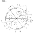
- the small-diameter drill 1 has a cutting edge 4, a cross thinning portion 5, and a chisel edge (not illustrated) at the front end.
- the small-diameter drill 1 has a flute (helical flute) 6 at the outer circumference of the body 2. Two pieces of the cutting edges 4, cross thinning portion 5, and flute 6 are disposed symmetrically around a rotation center.
- the cutting edge 4 consists of a thinning portion cutting edge 4b, and a flute portion cutting edge 4a that is connected to the outer end of the thinning portion cutting edge.
- the flute portion cutting edge 4a is curved in concave (that is, the shape of the flute portion cutting edge is a slight arc) against a rotational direction with respect to an imaginary straight line SL that connects a radially outer end P of the flute portion cutting edge 4a and a radially outer end Q of the thinning portion cutting edge 4b, and the degree of concavity d of the flute portion cutting edge 4a with respect to the imaginary straight line SL is set in a range of 0.5 to 2% of the drill diameter D.
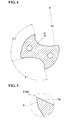
- the ratio B : A of the length B of the thinning portion cutting edge 4b to the length A of the flute portion cutting edge 4a is set to 0.6 to 0.9 : 1. Furthermore, in the axially perpendicular cross-sectional view of Fig. 4 , a curvature radius R1 of a flute surface 6b of the flute 6 on the heel 7 side illustrated in Fig. 3 is set to be smaller than a curvature radius R2 of a flute surface 6a along the flute portion cutting edge 4a.
- the curvature radius R2 of the flute surface of the flute 6 along the flute portion cutting edge is set in a range of 70 to 140% of the drill diameter D
- the curvature radius R1 of the heel-side flute surface is set in a range of 20 to 40% of the drill diameter D.
- a radial rake angle ⁇ (radial rake angle of the outer end of the flute portion cutting edge) is set to -7°.
- the core thickness of the body 2 be set to 0.30D to 0.37D and the flute width ratio ⁇ 1 : ⁇ 2 be set to 0.70 to 0.90 : 1.
- Setting the core thickness in the above-mentioned range enables the strength of the body to be assured without an insufficiency even with a drill used for high efficiency machining, and setting the flute width ratio ⁇ 1 : ⁇ 2 in the above-mentioned range enables satisfactory evacuation performance to be achieved even in high efficiency machining.
- the high efficiency machining referred herein means machining in which a feed is increased to approximately 3% of the drill diameter D.
- the cutting edge 4 be an edge that has undergone reinforcing treatment of round honing. Although it is preferable that no reinforcing treatment be made on the cutting edge from the viewpoint of sharpness, the reinforcing treatment of round honing achieves uniform wear of each portion of the cutting edge and also has favorable effect on chip processing performance.
- flank face 9 indicates a flank face
- 10 indicates an oil supply that is provided as needed.
- the flank face 9 is achieved by combining a second flank face and a third flank face, the flank face 9 may be a single conical flank face.
- Cemented carbide drills as the samples No. 1 to 12 illustrated in Table I were manufactured by way of trial with the specification that a body diameter D is ⁇ 1.3 mm, a flute length is 24 mm, a shank diameter D1 is ⁇ 3.0 mm, and a length is 65 mm.
- the curvature radius R2 of the flute surface of the flute along the flute portion cutting edge was 1.2mm, and the curvature radius R1 of the heel-side flute surface of the flute was 0.35 mm.
- the trial drills were manufactured by setting the core thickness, the flute width ratio ⁇ 1 : ⁇ 2, the shape of the flute portion cutting edge (listed as the shape of cutting edge in Table I), the degree of concavity d of the flute portion cutting edge with respect to the above-described imaginary straight line, and the ratio (listed as the ratio of lengths in Table I) of the length B of the thinning portion cutting edge to the length A of the flute portion cutting edge as in Table I, and the performance of each sample was evaluated.
- the evaluation test was conducted in the manner in which a hole was drilled in a workpiece of SUS416 under the following conditions.
- sample No. 3, sample No. 6, sample No.9 and sample No. 12 have a problem in chip processing performance, evacuation performance, strength of cutting edge, and/or machining accuracy, the sample No. 3 having the flute portion cutting edge in a straight line, the sample No. 6 having a degree of concavity of the flute portion cutting edge with respect to the above-mentioned imaginary straight line, the degree exceeding 2% of the drill diameter, the sample No. 9 and sample No. 12 having a ratio 0.6 or less and 0.9 or greater of the length of the thinning portion cutting edge to the length of the flute portion cutting edge. Also, in sample No. 7, chip may be somewhat stuck, and although not non-applicable, a variation in hole diameter occurs a little.
Abstract
Description
- The present invention relates to a drill (which is referred to as a small-diameter drill in the present invention) that has a diameter of 3 mm or less and is designed to achieve an improved machining performance while assuring the strength of a cutting edge.
- The small-diameter drill in the title tends to have an increased core thickness in order to ensure the strength. For a drill having an increased core thickness, a method of reducing thrust force is adopted, by which cross thinning (also referred to as X thinning) is applied to the drill.
- For a drill having an increased core thickness, cutting amount of a cutting edge is increased, and when the cutting edge of a flute (helical flute) portion is a straight line cutting edge, the radial rake angle (radial rake angle of the outer circumferential cutting edge) has a large negative angle, and thus an approach is adopted in which the flute portion cutting edge is curved in concave against a rotational direction of the drill so as to achieve a positive radial rake angle.
- As a conventional example of a small-diameter drill having such a design, there is one disclosed in, for example, PTL 1 listed below.
- PTL 1: Japanese Unexamined Patent Application Publication No.
2001-225216 - A drill having an increased core thickness has a flute with a shallow flute depth and a small flute area, and thus chip processing is difficult. In addition, a small-diameter drill has a low feed rate at the time of machining for rigidity reasons (the recommended condition of a feed for a conventional drill is 1% of the drill diameter), and thus processing of chip becomes more and more difficult.
- In the drill of PTL 1 mentioned above, almost the entire area of the flute surface of the flute has an approximately constant curvature radius, and thus when a workpiece is something like stainless steel which has a high toughness, segmentation processing of chip is difficult and stable chip processing performance is hardly expected.
- Also, a drill with the flute portion cutting edge curved in concave has reduced strength of the outer circumferential portion of the cutting edge and so the strength tends to be insufficient.
- Reduction in the strength of the outer circumferential portion of the cutting edge due to the curved in concave flute portion cutting edge can be recovered to some extent by performing return machining to set the radial rake angle to be, for example, 0°. However, it is not preferable that return machining be performed on a small-diameter drill because the return machining reduces the amount of back metal that affects to the strength.
- The problem to be solved by the present invention is how to restrain reduction in the strength of the outer circumferential portion of the cutting edge without providing a return portion while assuring sharpness of the outer circumferential portion of the cutting edge without an insufficiency, as well as how to achieve favorable machining accuracy and favorable chip processing performance.
- In order to solve the above-described problem, the present invention has implemented a small-diameter drill having a diameter of ϕ3mm or less and the end that has undergone cross thinning in the following manner. That is, in a front view, a flute portion cutting edge is curved to be concave against a rotational direction with respect to an imaginary straight line that connects a radially outer end of the flute portion cutting edge and a radially outer end of a thinning portion cutting edge, a degree of concavity d of the flute portion cutting edge with respect to the imaginary straight line is set in a range of 0.5 to 2% of a drill diameter D, furthermore, a ratio B : A of a length B of the thinning portion cutting edge to a length A of the flute portion cutting edge is set to 0.6 to 0.9 : 1, and in an axially perpendicular cross-sectional view, a curvature radius R1 of a heel-side flute surface of the flute is set to be smaller than a curvature radius R2 of a flute surface along the flute portion cutting edge.
- In such a small-diameter drill, when the radial rake angle γ of the radially outer end of the flute portion cutting edge is too small, sharpness of the outer circumferential portion of the cutting edge decreases, on the other hand when the radial rake angle γ is too large, sharpness of the outer circumferential portion of the cutting edge tends to be insufficient, and thus the radial rake angle γ is preferably set to -5 to -15°.
- Also it is preferable that the core thickness of the body be set to 0.30D to 0.37D and the flute width ratio θ1 : θ2 be set to 0.70 to 0.90 : 1.
- In addition, it is preferable that the cutting edge be an edge that has undergone reinforcing treatment of round honing with R radius of 0.005 to 0.015 mm. Advantageous Effects of Invention
- Since the flute portion cutting edge is curved in concave, the small-diameter drill of the present invention causes blunting of the radial rake angle to be restrained, and sharpness of the outer circumferential portion of the cutting edge can be increased without performing on the outer circumferential portion return machining which causes the amount of back metal to be reduced.
- In addition, by setting the degree of concavity d of the flute portion cutting edge in a range of 0.5 to 2% of the drill diameter D, reduction in the strength of the outer circumferential portion of the cutting edge is restrained.
- Furthermore, by setting the ratio of the length of the thinning portion cutting edge to the length of the flute portion cutting edge to 0.6 to 0.9 : 1, the balance between the cutting edges is maintained and accuracy in machining a hole is improved.
- Also, by setting the curvature radius of the heel-side flute surface of the flute to be smaller than the curvature radius of the flute surface along the flute portion cutting edge in an axially perpendicular cross-sectional view, the chip processing performance is also improved.
- That is, the chips generated by hole machining are usually curled and processed by the flow of chips generated by the flute portion cutting edge. However, with a small-diameter drill having a greater core thickness compared with a typical drill, chips (which have a greater thickness than the chips generated by the flute portion cutting edge) cut by the thinning portion cutting edge have a larger volume, and thus those chips generated by the flute portion cutting edge have less effect and the chips are not curled but tend to be extended, and so favorable evacuation is difficult to be achieved in deep hole machining.
- To cope with this problem, with the drill of the present invention, the chips generated by the flute portion cutting edge reach the heel side while the chips still have a relatively higher outflow energy. Therefore, those chips are guided to the heel-side flute surface having a small curvature radius to receive a large curl force, and due to its effect, the chips cut by the thinning portion cutting edge also flow along the flute without resistance, thereby achieving smooth evacuation of chips and delivering stable performance even in deep hole machining.
-
- [
Fig. 1] Figure 1 is a side view illustrating an example of a drill of the present invention. - [
Fig. 2] Figure 2 is an enlarged side view of the front end of the drill ofFig. 1 . - [
Fig. 3] Figure 3 is an enlarged front view of the drill ofFig. 1 . - [
Fig. 4] Figure 4 is an axially perpendicular cross-sectional view of the flutes of the drill. - [
Fig. 5] Figure 5 is an enlarged cross-sectional view taken along line V-V ofFig. 3 . Description of Embodiments - Hereinafter, an embodiment of a small-diameter drill of the present invention will be described with reference to
Figs. 1 to 5 in the accompanying drawings. - A small-diameter drill 1 illustrated is a step type two-edge drill, and includes a
body 2 having a diameter (= a machining diameter) D of 3 mm or less, and ashank 3 having a diameter larger than the diameter of the body. - The small-diameter drill 1 has a
cutting edge 4, across thinning portion 5, and a chisel edge (not illustrated) at the front end. In addition, the small-diameter drill 1 has a flute (helical flute) 6 at the outer circumference of thebody 2. Two pieces of thecutting edges 4, cross thinningportion 5, andflute 6 are disposed symmetrically around a rotation center. - The
cutting edge 4 consists of a thinningportion cutting edge 4b, and a fluteportion cutting edge 4a that is connected to the outer end of the thinning portion cutting edge. - In the front view of
Fig. 3 , the fluteportion cutting edge 4a is curved in concave (that is, the shape of the flute portion cutting edge is a slight arc) against a rotational direction with respect to an imaginary straight line SL that connects a radially outer end P of the fluteportion cutting edge 4a and a radially outer end Q of the thinningportion cutting edge 4b, and the degree of concavity d of the fluteportion cutting edge 4a with respect to the imaginary straight line SL is set in a range of 0.5 to 2% of the drill diameter D. - In addition, the ratio B : A of the length B of the thinning
portion cutting edge 4b to the length A of the fluteportion cutting edge 4a is set to 0.6 to 0.9 : 1. Furthermore, in the axially perpendicular cross-sectional view ofFig. 4 , a curvature radius R1 of aflute surface 6b of theflute 6 on theheel 7 side illustrated inFig. 3 is set to be smaller than a curvature radius R2 of aflute surface 6a along the fluteportion cutting edge 4a. - The curvature radius R2 of the flute surface of the
flute 6 along the flute portion cutting edge is set in a range of 70 to 140% of the drill diameter D, and the curvature radius R1 of the heel-side flute surface is set in a range of 20 to 40% of the drill diameter D. - In addition, in the drill illustrated, a radial rake angle γ (radial rake angle of the outer end of the flute portion cutting edge) is set to -7°.
- In the drill of the present invention, it is preferable that the core thickness of the
body 2 be set to 0.30D to 0.37D and the flute width ratio θ1 : θ2 be set to 0.70 to 0.90 : 1. Setting the core thickness in the above-mentioned range enables the strength of the body to be assured without an insufficiency even with a drill used for high efficiency machining, and setting the flute width ratio θ1 : θ2 in the above-mentioned range enables satisfactory evacuation performance to be achieved even in high efficiency machining. The high efficiency machining referred herein means machining in which a feed is increased to approximately 3% of the drill diameter D. - In addition, as illustrated in
Fig. 5 , it is preferable that thecutting edge 4 be an edge that has undergone reinforcing treatment of round honing. Although it is preferable that no reinforcing treatment be made on the cutting edge from the viewpoint of sharpness, the reinforcing treatment of round honing achieves uniform wear of each portion of the cutting edge and also has favorable effect on chip processing performance. - In
Fig. 3 , 7 indicates a heel, 8 indicates a margin, 9 indicates a flank face, and 10 indicates an oil supply that is provided as needed. Although theflank face 9 is achieved by combining a second flank face and a third flank face, theflank face 9 may be a single conical flank face. - Cemented carbide drills as the samples No. 1 to 12 illustrated in Table I were manufactured by way of trial with the specification that a body diameter D is ϕ1.3 mm, a flute length is 24 mm, a shank diameter D1 is ϕ3.0 mm, and a length is 65 mm. The curvature radius R2 of the flute surface of the flute along the flute portion cutting edge was 1.2mm, and the curvature radius R1 of the heel-side flute surface of the flute was 0.35 mm. The trial drills were manufactured by setting the core thickness, the flute width ratio θ1 : θ2, the shape of the flute portion cutting edge (listed as the shape of cutting edge in Table I), the degree of concavity d of the flute portion cutting edge with respect to the above-described imaginary straight line, and the ratio (listed as the ratio of lengths in Table I) of the length B of the thinning portion cutting edge to the length A of the flute portion cutting edge as in Table I, and the performance of each sample was evaluated.
- The evaluation test was conducted in the manner in which a hole was drilled in a workpiece of SUS416 under the following conditions.
- Machining conditions: an outer circumferential cutting speed Vc = 80 m/min, feed f = 0.03 mm, machined hole depth H = 20 mm, and internal oil supply wet machining applied
- The result of the test is summarized in Table II.
[Table I] Sample No. Design Core thickness Flute width ratio Shape of cutting edge Degree of concavity Ratio of lengths B : A 1 0.30D 0.80:1 Slight arc 0.015D 0.6:1 2 0.35D 0.80:1 Slight arc 0.015D 0.8:1 3 0.30D 0.8:1 Straight line 0 0.8:1 4 0.30D 0.80:1 Slight arc 0.005D 0.8:1 5 0.30D 0.80:1 Slight arc 0.020D 0.8:1 6 0.30D 0.80:1 Slight arc 0.03D 0.8:1 7 0.30D 0.60:1 Slight arc 0.015D 0.8:1 8 0.30D 0.90:1 Slight arc 0.015D 0.8:1 9 0.30D 0.80:1 Slight arc 0.015D 0.5:1 10 0.30D 0.80:1 Slight arc 0.015D 0.6:1 11 0.30D 0.80:1 Slight arc 0.015D 0.9:1 12 0.30D 0.80:1 Slight arc 0.015D 1:1 [Table II] Sample No. Evaluation items Applicability determination Drill strength Strength of outer circumferential cutting edge Chip processing Chip evaluation Variation in hole diameter 1 ○ ○ ○ ○ ○ ○ 2 ○ ○ ○ ○ ○ ○ 3 ○ ○ × × ○ × 4 ○ ○ ○ ○ ○ ○ 5 ○ ○ ○ ○ ○ ○ 6 ○ × ○ ○ ○ × 7 ○ ○ ○ ○ ○ ○ 8 ○ ○ ○ ○ ○ ○ 9 ○ ○ ○ ○ × × 10 ○ ○ ○ ○ ○ ○ 11 ○ ○ ○ ○ ○ ○ 12 ○ ○ × × × × Evaluation items: ○ satisfactory, × unsatisfactory Applicability determination: ○ applicable, × non-applicable - As seen from the test result of Table II, sample No. 3, sample No. 6, sample No.9 and sample No. 12 have a problem in chip processing performance, evacuation performance, strength of cutting edge, and/or machining accuracy, the sample No. 3 having the flute portion cutting edge in a straight line, the sample No. 6 having a degree of concavity of the flute portion cutting edge with respect to the above-mentioned imaginary straight line, the degree exceeding 2% of the drill diameter, the sample No. 9 and sample No. 12 having a ratio 0.6 or less and 0.9 or greater of the length of the thinning portion cutting edge to the length of the flute portion cutting edge. Also, in sample No. 7, chip may be somewhat stuck, and although not non-applicable, a variation in hole diameter occurs a little.
- On the other hand, favorable results were obtained in all evaluation items for the samples in which the degree of concavity and the ratio of the lengths of the cutting edges at the thinning portion and the flute portion satisfy the specified ranges of the present application.
- Results with almost no difference from the evaluation results of Table II were obtained in machining under the conditions that the feed is 0.04 mm, 0.05 mm and the rest of the conditions are the same as those in the above-described examples.
- The configuration of the embodiment of the present invention disclosed above has been described by way of example only, and the scope of the present invention is not limited to the scope of the description. The scope of the present invention is indicated by the description of the claims, and is further intended to include any modifications within the scope and meaning equivalent to the description of the claims.
-
- 1
- small-diameter drill
- 2
- body
- 3
- shank
- 4
- cutting edge
- 4a
- flute portion cutting edge
- 4b
- thinning cutting edge
- 5
- cross thinning portion
- 6
- flute
- 7
- heel
- 8
- margin
- 9
- flank face
- 10
- oil supply
- P
- radially outer end of flute portion cutting edge
- Q
- radially outer end of thinning cutting edge
- SL
- imaginary straight line connecting P and Q
- d
- degree of concavity of flute portion
- R1
- curvature radius of heel-side flute surface of flute
- R2
- curvature radius of flute surface along flute portion cutting edge of flute
Claims (4)
- A small-diameter drill having a diameter of ϕ3mm or less and an end that has undergone cross thinning,
wherein in a front view, a flute portion cutting edge is curved in concave against a rotational direction with respect to an imaginary straight line that connects a radially outer end of the flute portion cutting edge and a radially outer end of a thinning portion cutting edge, a degree of concavity of the flute portion cutting edge with respect to the imaginary straight line is set in a range of 0.5 to 2% of a drill diameter, furthermore, a ratio B : A of a length B of the thinning portion cutting edge to a length A of the flute portion cutting edge is set to 0.6 to 0.9 : 1, and in an axially perpendicular cross-sectional view, a curvature radius R1 of a heel-side flute surface of a flute is set to be smaller than a curvature radius R2 of a flute surface along the flute portion cutting edge. - The small-diameter drill according to claim 1,
wherein a radial rake angle γ of a radially outer end of the flute portion cutting edge is set to -5 to -15°. - The small-diameter drill according to claim 1 or 2,
wherein a core thickness is set to 0.30D to 0.37D and a flute width ratio θ1 : θ2 is set to 0.70 to 0.90 : 1. - The small-diameter drill according to any one of claims 1 to 3,
wherein the cutting edge has undergone reinforcing treatment of round honing with R radius of 0.005 to 0.015 mm.
Applications Claiming Priority (2)
| Application Number | Priority Date | Filing Date | Title |
|---|---|---|---|
| JP2012235463A JP5927671B2 (en) | 2012-10-25 | 2012-10-25 | Small diameter drill |
| PCT/JP2013/078804 WO2014065361A1 (en) | 2012-10-25 | 2013-10-24 | Small-diameter drill |
Publications (3)
| Publication Number | Publication Date |
|---|---|
| EP2913131A1 true EP2913131A1 (en) | 2015-09-02 |
| EP2913131A4 EP2913131A4 (en) | 2015-10-14 |
| EP2913131B1 EP2913131B1 (en) | 2016-08-17 |
Family
ID=50544734
Family Applications (1)
| Application Number | Title | Priority Date | Filing Date |
|---|---|---|---|
| EP13848502.4A Active EP2913131B1 (en) | 2012-10-25 | 2013-10-24 | Small-diameter drill |
Country Status (5)
| Country | Link |
|---|---|
| US (1) | US9522428B2 (en) |
| EP (1) | EP2913131B1 (en) |
| JP (1) | JP5927671B2 (en) |
| CN (1) | CN104755210B (en) |
| WO (1) | WO2014065361A1 (en) |
Cited By (1)
| Publication number | Priority date | Publication date | Assignee | Title |
|---|---|---|---|---|
| US11642728B2 (en) | 2016-12-28 | 2023-05-09 | Seco Tools Ab | Twist drill and an exchangeable head for a twist drill |
Families Citing this family (11)
| Publication number | Priority date | Publication date | Assignee | Title |
|---|---|---|---|---|
| JP6174700B2 (en) * | 2013-06-26 | 2017-08-02 | 京セラ株式会社 | drill |
| JP6268809B2 (en) | 2013-08-22 | 2018-01-31 | 三菱マテリアル株式会社 | drill |
| JP6848176B2 (en) * | 2016-01-15 | 2021-03-24 | 株式会社Moldino | Drill |
| JP1568741S (en) * | 2016-09-09 | 2017-02-06 | ||
| JP1581012S (en) * | 2016-11-17 | 2017-07-10 | ||
| TWI651141B (en) * | 2017-11-03 | 2019-02-21 | 創國興業有限公司 | Drill structure |
| CN109262025B (en) * | 2018-10-29 | 2020-05-15 | 株洲钻石切削刀具股份有限公司 | Drilling tool |
| CN110076375A (en) * | 2019-05-05 | 2019-08-02 | 厦门金鹭特种合金有限公司 | A kind of monoblock type fluted drill |
| JP6750790B1 (en) * | 2019-10-15 | 2020-09-02 | 住友電工ハードメタル株式会社 | Drill |
| DE102020200225A1 (en) * | 2020-01-10 | 2021-07-15 | Ibeo Automotive Systems GmbH | Test procedure and test arrangement for functional validation for optical detection systems |
| EP4316710A1 (en) * | 2021-03-23 | 2024-02-07 | Sumitomo Electric Hardmetal Corp. | Drill head, tip-interchangeable drill, and drill |
Family Cites Families (21)
| Publication number | Priority date | Publication date | Assignee | Title |
|---|---|---|---|---|
| US4602900A (en) * | 1979-10-01 | 1986-07-29 | Arpaio Jr Jerry | Micro drill with modified drill point |
| JPS57107716A (en) * | 1980-12-25 | 1982-07-05 | Tanaka Kikinzoku Kogyo Kk | Drill |
| JPS59219108A (en) * | 1983-05-25 | 1984-12-10 | Sumitomo Electric Ind Ltd | Drill |
| JPS60120712U (en) * | 1984-01-25 | 1985-08-15 | 住友電気工業株式会社 | Drill |
| JPS60120713U (en) * | 1984-01-25 | 1985-08-15 | 住友電気工業株式会社 | Drill |
| US5888036A (en) * | 1990-02-27 | 1999-03-30 | Hitachi Seiko, Ltd. | Drill bit and step feeding method |
| JP2001225216A (en) | 2000-02-10 | 2001-08-21 | Kobe Steel Ltd | Drill for machining small-diameter hole |
| JP2004025383A (en) * | 2002-06-27 | 2004-01-29 | Dijet Ind Co Ltd | Twist drill |
| JP4725369B2 (en) * | 2006-03-03 | 2011-07-13 | 三菱マテリアル株式会社 | Drill |
| JP2007229899A (en) * | 2006-03-03 | 2007-09-13 | Mitsubishi Materials Corp | Drill |
| JP2008296300A (en) * | 2007-05-30 | 2008-12-11 | Tungaloy Corp | Drill for printed circuit board |
| JP2009018360A (en) * | 2007-07-10 | 2009-01-29 | Sumitomo Electric Hardmetal Corp | Drill for metal working |
| US8545141B2 (en) * | 2007-10-26 | 2013-10-01 | Sumitomo Electric Hardmetal Corp. | Twist drill |
| JP2010274409A (en) * | 2009-05-29 | 2010-12-09 | Hitachi Tool Engineering Ltd | Small diameter drill for machining machinable ceramics |
| DE102009025223A1 (en) * | 2009-06-08 | 2010-12-09 | MAPAL Fabrik für Präzisionswerkzeuge Dr. Kress KG | drill |
| JP2012030306A (en) * | 2010-07-29 | 2012-02-16 | Hitachi Tool Engineering Ltd | Drill and drilling method using the same |
| TWI446980B (en) * | 2010-11-26 | 2014-08-01 | Tungaloy Corp | Small diameter drill |
| CN202062106U (en) * | 2011-03-25 | 2011-12-07 | 闵航 | Chip breaking drill |
| CN202239818U (en) * | 2011-07-11 | 2012-05-30 | 深圳市航天精密刀具有限公司 | Hard alloy drill bit |
| CN102389991A (en) * | 2011-12-06 | 2012-03-28 | 株洲钻石切削刀具股份有限公司 | Double-margin twist drill |
| JP6174700B2 (en) * | 2013-06-26 | 2017-08-02 | 京セラ株式会社 | drill |
-
2012
- 2012-10-25 JP JP2012235463A patent/JP5927671B2/en active Active
-
2013
- 2013-10-24 US US14/434,904 patent/US9522428B2/en active Active
- 2013-10-24 WO PCT/JP2013/078804 patent/WO2014065361A1/en active Application Filing
- 2013-10-24 EP EP13848502.4A patent/EP2913131B1/en active Active
- 2013-10-24 CN CN201380055624.7A patent/CN104755210B/en active Active
Cited By (1)
| Publication number | Priority date | Publication date | Assignee | Title |
|---|---|---|---|---|
| US11642728B2 (en) | 2016-12-28 | 2023-05-09 | Seco Tools Ab | Twist drill and an exchangeable head for a twist drill |
Also Published As
| Publication number | Publication date |
|---|---|
| CN104755210A (en) | 2015-07-01 |
| US20150283624A1 (en) | 2015-10-08 |
| EP2913131B1 (en) | 2016-08-17 |
| JP2014083645A (en) | 2014-05-12 |
| WO2014065361A1 (en) | 2014-05-01 |
| CN104755210B (en) | 2017-03-08 |
| US9522428B2 (en) | 2016-12-20 |
| EP2913131A4 (en) | 2015-10-14 |
| JP5927671B2 (en) | 2016-06-01 |
Similar Documents
| Publication | Publication Date | Title |
|---|---|---|
| EP2913131B1 (en) | Small-diameter drill | |
| JP6611260B2 (en) | drill | |
| US8870498B2 (en) | Ball end mill | |
| US9511424B2 (en) | Drill | |
| JP4894054B2 (en) | Twist drill | |
| CN106132607B (en) | Rotary cutting tool with polycrystalline diamond sintered body | |
| US9492877B2 (en) | Drill | |
| EP2698219A1 (en) | Drill | |
| CN111093871B (en) | Drill bit | |
| EP3015203A1 (en) | Drill | |
| US10220451B2 (en) | End mill and method for manufacturing machined product | |
| JP6268716B2 (en) | drill | |
| EP3195966A1 (en) | Drill | |
| WO2010086988A1 (en) | Double angle drill | |
| JP2008142834A (en) | Drill | |
| JP5077996B2 (en) | Carbide twist drill | |
| JP7206496B2 (en) | Drill | |
| EP4066972A1 (en) | Rotary cutting tool | |
| WO2021074958A1 (en) | Drill | |
| WO2010050390A1 (en) | Ball end mill | |
| JP2001129715A (en) | End mill | |
| JP3909783B2 (en) | Gun drill with diamond sintered body | |
| WO2023210572A1 (en) | Drill | |
| JP2005205526A (en) | Deep hole boring tool | |
| JP2002028810A (en) | Small-sized drill |
Legal Events
| Date | Code | Title | Description |
|---|---|---|---|
| PUAI | Public reference made under article 153(3) epc to a published international application that has entered the european phase |
Free format text: ORIGINAL CODE: 0009012 |
|
| 17P | Request for examination filed |
Effective date: 20150417 |
|
| AK | Designated contracting states |
Kind code of ref document: A1 Designated state(s): AL AT BE BG CH CY CZ DE DK EE ES FI FR GB GR HR HU IE IS IT LI LT LU LV MC MK MT NL NO PL PT RO RS SE SI SK SM TR |
|
| AX | Request for extension of the european patent |
Extension state: BA ME |
|
| RA4 | Supplementary search report drawn up and despatched (corrected) |
Effective date: 20150914 |
|
| RIC1 | Information provided on ipc code assigned before grant |
Ipc: B23B 51/06 20060101ALI20150908BHEP Ipc: B23B 51/02 20060101AFI20150908BHEP |
|
| DAX | Request for extension of the european patent (deleted) | ||
| REG | Reference to a national code |
Ref country code: DE Ref legal event code: R079 Ref document number: 602013010498 Country of ref document: DE Free format text: PREVIOUS MAIN CLASS: B23B0051000000 Ipc: B23B0051020000 |
|
| GRAP | Despatch of communication of intention to grant a patent |
Free format text: ORIGINAL CODE: EPIDOSNIGR1 |
|
| RIC1 | Information provided on ipc code assigned before grant |
Ipc: B23B 51/02 20060101AFI20160217BHEP Ipc: B23B 51/06 20060101ALI20160217BHEP |
|
| INTG | Intention to grant announced |
Effective date: 20160309 |
|
| GRAS | Grant fee paid |
Free format text: ORIGINAL CODE: EPIDOSNIGR3 |
|
| GRAA | (expected) grant |
Free format text: ORIGINAL CODE: 0009210 |
|
| AK | Designated contracting states |
Kind code of ref document: B1 Designated state(s): AL AT BE BG CH CY CZ DE DK EE ES FI FR GB GR HR HU IE IS IT LI LT LU LV MC MK MT NL NO PL PT RO RS SE SI SK SM TR |
|
| REG | Reference to a national code |
Ref country code: GB Ref legal event code: FG4D |
|
| REG | Reference to a national code |
Ref country code: CH Ref legal event code: EP |
|
| REG | Reference to a national code |
Ref country code: IE Ref legal event code: FG4D |
|
| REG | Reference to a national code |
Ref country code: AT Ref legal event code: REF Ref document number: 820582 Country of ref document: AT Kind code of ref document: T Effective date: 20160915 |
|
| REG | Reference to a national code |
Ref country code: DE Ref legal event code: R096 Ref document number: 602013010498 Country of ref document: DE |
|
| REG | Reference to a national code |
Ref country code: NL Ref legal event code: MP Effective date: 20160817 |
|
| REG | Reference to a national code |
Ref country code: LT Ref legal event code: MG4D |
|
| REG | Reference to a national code |
Ref country code: AT Ref legal event code: MK05 Ref document number: 820582 Country of ref document: AT Kind code of ref document: T Effective date: 20160817 |
|
| PG25 | Lapsed in a contracting state [announced via postgrant information from national office to epo] |
Ref country code: LT Free format text: LAPSE BECAUSE OF FAILURE TO SUBMIT A TRANSLATION OF THE DESCRIPTION OR TO PAY THE FEE WITHIN THE PRESCRIBED TIME-LIMIT Effective date: 20160817 Ref country code: RS Free format text: LAPSE BECAUSE OF FAILURE TO SUBMIT A TRANSLATION OF THE DESCRIPTION OR TO PAY THE FEE WITHIN THE PRESCRIBED TIME-LIMIT Effective date: 20160817 Ref country code: NO Free format text: LAPSE BECAUSE OF FAILURE TO SUBMIT A TRANSLATION OF THE DESCRIPTION OR TO PAY THE FEE WITHIN THE PRESCRIBED TIME-LIMIT Effective date: 20161117 Ref country code: NL Free format text: LAPSE BECAUSE OF FAILURE TO SUBMIT A TRANSLATION OF THE DESCRIPTION OR TO PAY THE FEE WITHIN THE PRESCRIBED TIME-LIMIT Effective date: 20160817 Ref country code: IT Free format text: LAPSE BECAUSE OF FAILURE TO SUBMIT A TRANSLATION OF THE DESCRIPTION OR TO PAY THE FEE WITHIN THE PRESCRIBED TIME-LIMIT Effective date: 20160817 Ref country code: FI Free format text: LAPSE BECAUSE OF FAILURE TO SUBMIT A TRANSLATION OF THE DESCRIPTION OR TO PAY THE FEE WITHIN THE PRESCRIBED TIME-LIMIT Effective date: 20160817 Ref country code: HR Free format text: LAPSE BECAUSE OF FAILURE TO SUBMIT A TRANSLATION OF THE DESCRIPTION OR TO PAY THE FEE WITHIN THE PRESCRIBED TIME-LIMIT Effective date: 20160817 |
|
| PG25 | Lapsed in a contracting state [announced via postgrant information from national office to epo] |
Ref country code: ES Free format text: LAPSE BECAUSE OF FAILURE TO SUBMIT A TRANSLATION OF THE DESCRIPTION OR TO PAY THE FEE WITHIN THE PRESCRIBED TIME-LIMIT Effective date: 20160817 Ref country code: GR Free format text: LAPSE BECAUSE OF FAILURE TO SUBMIT A TRANSLATION OF THE DESCRIPTION OR TO PAY THE FEE WITHIN THE PRESCRIBED TIME-LIMIT Effective date: 20161118 Ref country code: BE Free format text: LAPSE BECAUSE OF NON-PAYMENT OF DUE FEES Effective date: 20161031 Ref country code: AT Free format text: LAPSE BECAUSE OF FAILURE TO SUBMIT A TRANSLATION OF THE DESCRIPTION OR TO PAY THE FEE WITHIN THE PRESCRIBED TIME-LIMIT Effective date: 20160817 Ref country code: PT Free format text: LAPSE BECAUSE OF FAILURE TO SUBMIT A TRANSLATION OF THE DESCRIPTION OR TO PAY THE FEE WITHIN THE PRESCRIBED TIME-LIMIT Effective date: 20161219 Ref country code: LV Free format text: LAPSE BECAUSE OF FAILURE TO SUBMIT A TRANSLATION OF THE DESCRIPTION OR TO PAY THE FEE WITHIN THE PRESCRIBED TIME-LIMIT Effective date: 20160817 Ref country code: SE Free format text: LAPSE BECAUSE OF FAILURE TO SUBMIT A TRANSLATION OF THE DESCRIPTION OR TO PAY THE FEE WITHIN THE PRESCRIBED TIME-LIMIT Effective date: 20160817 Ref country code: PL Free format text: LAPSE BECAUSE OF FAILURE TO SUBMIT A TRANSLATION OF THE DESCRIPTION OR TO PAY THE FEE WITHIN THE PRESCRIBED TIME-LIMIT Effective date: 20160817 |
|
| PG25 | Lapsed in a contracting state [announced via postgrant information from national office to epo] |
Ref country code: RO Free format text: LAPSE BECAUSE OF FAILURE TO SUBMIT A TRANSLATION OF THE DESCRIPTION OR TO PAY THE FEE WITHIN THE PRESCRIBED TIME-LIMIT Effective date: 20160817 Ref country code: EE Free format text: LAPSE BECAUSE OF FAILURE TO SUBMIT A TRANSLATION OF THE DESCRIPTION OR TO PAY THE FEE WITHIN THE PRESCRIBED TIME-LIMIT Effective date: 20160817 |
|
| REG | Reference to a national code |
Ref country code: DE Ref legal event code: R097 Ref document number: 602013010498 Country of ref document: DE |
|
| PG25 | Lapsed in a contracting state [announced via postgrant information from national office to epo] |
Ref country code: SK Free format text: LAPSE BECAUSE OF FAILURE TO SUBMIT A TRANSLATION OF THE DESCRIPTION OR TO PAY THE FEE WITHIN THE PRESCRIBED TIME-LIMIT Effective date: 20160817 Ref country code: CZ Free format text: LAPSE BECAUSE OF FAILURE TO SUBMIT A TRANSLATION OF THE DESCRIPTION OR TO PAY THE FEE WITHIN THE PRESCRIBED TIME-LIMIT Effective date: 20160817 Ref country code: BE Free format text: LAPSE BECAUSE OF FAILURE TO SUBMIT A TRANSLATION OF THE DESCRIPTION OR TO PAY THE FEE WITHIN THE PRESCRIBED TIME-LIMIT Effective date: 20160817 Ref country code: DK Free format text: LAPSE BECAUSE OF FAILURE TO SUBMIT A TRANSLATION OF THE DESCRIPTION OR TO PAY THE FEE WITHIN THE PRESCRIBED TIME-LIMIT Effective date: 20160817 Ref country code: SM Free format text: LAPSE BECAUSE OF FAILURE TO SUBMIT A TRANSLATION OF THE DESCRIPTION OR TO PAY THE FEE WITHIN THE PRESCRIBED TIME-LIMIT Effective date: 20160817 Ref country code: BG Free format text: LAPSE BECAUSE OF FAILURE TO SUBMIT A TRANSLATION OF THE DESCRIPTION OR TO PAY THE FEE WITHIN THE PRESCRIBED TIME-LIMIT Effective date: 20161117 |
|
| REG | Reference to a national code |
Ref country code: CH Ref legal event code: PL |
|
| PLBE | No opposition filed within time limit |
Free format text: ORIGINAL CODE: 0009261 |
|
| STAA | Information on the status of an ep patent application or granted ep patent |
Free format text: STATUS: NO OPPOSITION FILED WITHIN TIME LIMIT |
|
| 26N | No opposition filed |
Effective date: 20170518 |
|
| REG | Reference to a national code |
Ref country code: IE Ref legal event code: MM4A |
|
| REG | Reference to a national code |
Ref country code: FR Ref legal event code: ST Effective date: 20170630 |
|
| PG25 | Lapsed in a contracting state [announced via postgrant information from national office to epo] |
Ref country code: CH Free format text: LAPSE BECAUSE OF NON-PAYMENT OF DUE FEES Effective date: 20161031 Ref country code: LI Free format text: LAPSE BECAUSE OF NON-PAYMENT OF DUE FEES Effective date: 20161031 Ref country code: FR Free format text: LAPSE BECAUSE OF NON-PAYMENT OF DUE FEES Effective date: 20161102 |
|
| PG25 | Lapsed in a contracting state [announced via postgrant information from national office to epo] |
Ref country code: LU Free format text: LAPSE BECAUSE OF NON-PAYMENT OF DUE FEES Effective date: 20161024 Ref country code: SI Free format text: LAPSE BECAUSE OF FAILURE TO SUBMIT A TRANSLATION OF THE DESCRIPTION OR TO PAY THE FEE WITHIN THE PRESCRIBED TIME-LIMIT Effective date: 20160817 |
|
| PG25 | Lapsed in a contracting state [announced via postgrant information from national office to epo] |
Ref country code: IE Free format text: LAPSE BECAUSE OF NON-PAYMENT OF DUE FEES Effective date: 20161024 |
|
| PG25 | Lapsed in a contracting state [announced via postgrant information from national office to epo] |
Ref country code: HU Free format text: LAPSE BECAUSE OF FAILURE TO SUBMIT A TRANSLATION OF THE DESCRIPTION OR TO PAY THE FEE WITHIN THE PRESCRIBED TIME-LIMIT; INVALID AB INITIO Effective date: 20131024 |
|
| GBPC | Gb: european patent ceased through non-payment of renewal fee |
Effective date: 20171024 |
|
| PG25 | Lapsed in a contracting state [announced via postgrant information from national office to epo] |
Ref country code: CY Free format text: LAPSE BECAUSE OF FAILURE TO SUBMIT A TRANSLATION OF THE DESCRIPTION OR TO PAY THE FEE WITHIN THE PRESCRIBED TIME-LIMIT Effective date: 20160817 Ref country code: IS Free format text: LAPSE BECAUSE OF FAILURE TO SUBMIT A TRANSLATION OF THE DESCRIPTION OR TO PAY THE FEE WITHIN THE PRESCRIBED TIME-LIMIT Effective date: 20160817 Ref country code: MC Free format text: LAPSE BECAUSE OF FAILURE TO SUBMIT A TRANSLATION OF THE DESCRIPTION OR TO PAY THE FEE WITHIN THE PRESCRIBED TIME-LIMIT Effective date: 20160817 Ref country code: MT Free format text: LAPSE BECAUSE OF NON-PAYMENT OF DUE FEES Effective date: 20161031 Ref country code: MK Free format text: LAPSE BECAUSE OF FAILURE TO SUBMIT A TRANSLATION OF THE DESCRIPTION OR TO PAY THE FEE WITHIN THE PRESCRIBED TIME-LIMIT Effective date: 20160817 |
|
| PG25 | Lapsed in a contracting state [announced via postgrant information from national office to epo] |
Ref country code: GB Free format text: LAPSE BECAUSE OF NON-PAYMENT OF DUE FEES Effective date: 20171024 |
|
| PG25 | Lapsed in a contracting state [announced via postgrant information from national office to epo] |
Ref country code: AL Free format text: LAPSE BECAUSE OF FAILURE TO SUBMIT A TRANSLATION OF THE DESCRIPTION OR TO PAY THE FEE WITHIN THE PRESCRIBED TIME-LIMIT Effective date: 20160817 Ref country code: TR Free format text: LAPSE BECAUSE OF FAILURE TO SUBMIT A TRANSLATION OF THE DESCRIPTION OR TO PAY THE FEE WITHIN THE PRESCRIBED TIME-LIMIT Effective date: 20160817 |
|
| P01 | Opt-out of the competence of the unified patent court (upc) registered |
Effective date: 20230515 |
|
| PGFP | Annual fee paid to national office [announced via postgrant information from national office to epo] |
Ref country code: DE Payment date: 20230830 Year of fee payment: 11 |