EP2913118A1 - Method for manufacturing flat pipe - Google Patents
Method for manufacturing flat pipe Download PDFInfo
- Publication number
- EP2913118A1 EP2913118A1 EP13850999.7A EP13850999A EP2913118A1 EP 2913118 A1 EP2913118 A1 EP 2913118A1 EP 13850999 A EP13850999 A EP 13850999A EP 2913118 A1 EP2913118 A1 EP 2913118A1
- Authority
- EP
- European Patent Office
- Prior art keywords
- flat pipe
- thin plate
- manufacturing
- cut
- expanded shape
- Prior art date
- Legal status (The legal status is an assumption and is not a legal conclusion. Google has not performed a legal analysis and makes no representation as to the accuracy of the status listed.)
- Withdrawn
Links
- 238000004519 manufacturing process Methods 0.000 title claims abstract description 35
- 238000000034 method Methods 0.000 title claims abstract description 19
- 229910052751 metal Inorganic materials 0.000 claims abstract description 5
- 239000002184 metal Substances 0.000 claims abstract description 5
- 238000003754 machining Methods 0.000 claims abstract description 3
- 238000005304 joining Methods 0.000 description 13
- 238000003466 welding Methods 0.000 description 9
- 239000000463 material Substances 0.000 description 5
- 238000007796 conventional method Methods 0.000 description 4
- 230000002708 enhancing effect Effects 0.000 description 4
- 239000007769 metal material Substances 0.000 description 4
- 238000012546 transfer Methods 0.000 description 3
- CURLTUGMZLYLDI-UHFFFAOYSA-N Carbon dioxide Chemical compound O=C=O CURLTUGMZLYLDI-UHFFFAOYSA-N 0.000 description 2
- CWYNVVGOOAEACU-UHFFFAOYSA-N Fe2+ Chemical compound [Fe+2] CWYNVVGOOAEACU-UHFFFAOYSA-N 0.000 description 2
- PXHVJJICTQNCMI-UHFFFAOYSA-N Nickel Chemical compound [Ni] PXHVJJICTQNCMI-UHFFFAOYSA-N 0.000 description 2
- 229910052782 aluminium Inorganic materials 0.000 description 2
- XAGFODPZIPBFFR-UHFFFAOYSA-N aluminium Chemical compound [Al] XAGFODPZIPBFFR-UHFFFAOYSA-N 0.000 description 2
- 230000000694 effects Effects 0.000 description 2
- 238000010438 heat treatment Methods 0.000 description 2
- 230000001965 increasing effect Effects 0.000 description 2
- BASFCYQUMIYNBI-UHFFFAOYSA-N platinum Chemical compound [Pt] BASFCYQUMIYNBI-UHFFFAOYSA-N 0.000 description 2
- RYGMFSIKBFXOCR-UHFFFAOYSA-N Copper Chemical compound [Cu] RYGMFSIKBFXOCR-UHFFFAOYSA-N 0.000 description 1
- ZOKXTWBITQBERF-UHFFFAOYSA-N Molybdenum Chemical compound [Mo] ZOKXTWBITQBERF-UHFFFAOYSA-N 0.000 description 1
- BQCADISMDOOEFD-UHFFFAOYSA-N Silver Chemical compound [Ag] BQCADISMDOOEFD-UHFFFAOYSA-N 0.000 description 1
- ATJFFYVFTNAWJD-UHFFFAOYSA-N Tin Chemical compound [Sn] ATJFFYVFTNAWJD-UHFFFAOYSA-N 0.000 description 1
- RTAQQCXQSZGOHL-UHFFFAOYSA-N Titanium Chemical compound [Ti] RTAQQCXQSZGOHL-UHFFFAOYSA-N 0.000 description 1
- 239000000853 adhesive Substances 0.000 description 1
- 230000001070 adhesive effect Effects 0.000 description 1
- 229910045601 alloy Inorganic materials 0.000 description 1
- 239000000956 alloy Substances 0.000 description 1
- 230000015572 biosynthetic process Effects 0.000 description 1
- 238000005219 brazing Methods 0.000 description 1
- 229910002092 carbon dioxide Inorganic materials 0.000 description 1
- 239000001569 carbon dioxide Substances 0.000 description 1
- 239000011248 coating agent Substances 0.000 description 1
- 238000000576 coating method Methods 0.000 description 1
- 229910017052 cobalt Inorganic materials 0.000 description 1
- 239000010941 cobalt Substances 0.000 description 1
- GUTLYIVDDKVIGB-UHFFFAOYSA-N cobalt atom Chemical compound [Co] GUTLYIVDDKVIGB-UHFFFAOYSA-N 0.000 description 1
- 229910052802 copper Inorganic materials 0.000 description 1
- 239000010949 copper Substances 0.000 description 1
- 238000005755 formation reaction Methods 0.000 description 1
- PCHJSUWPFVWCPO-UHFFFAOYSA-N gold Chemical compound [Au] PCHJSUWPFVWCPO-UHFFFAOYSA-N 0.000 description 1
- 229910052737 gold Inorganic materials 0.000 description 1
- 239000010931 gold Substances 0.000 description 1
- 238000012986 modification Methods 0.000 description 1
- 230000004048 modification Effects 0.000 description 1
- 229910052750 molybdenum Inorganic materials 0.000 description 1
- 239000011733 molybdenum Substances 0.000 description 1
- 229910052759 nickel Inorganic materials 0.000 description 1
- 238000007747 plating Methods 0.000 description 1
- 229910052697 platinum Inorganic materials 0.000 description 1
- 239000010970 precious metal Substances 0.000 description 1
- 239000003870 refractory metal Substances 0.000 description 1
- 229910052709 silver Inorganic materials 0.000 description 1
- 239000004332 silver Substances 0.000 description 1
- 238000005476 soldering Methods 0.000 description 1
- 239000010935 stainless steel Substances 0.000 description 1
- 229910001220 stainless steel Inorganic materials 0.000 description 1
- 239000010936 titanium Substances 0.000 description 1
- 229910052719 titanium Inorganic materials 0.000 description 1
- 238000012800 visualization Methods 0.000 description 1
Images



Classifications
-
- B—PERFORMING OPERATIONS; TRANSPORTING
- B21—MECHANICAL METAL-WORKING WITHOUT ESSENTIALLY REMOVING MATERIAL; PUNCHING METAL
- B21D—WORKING OR PROCESSING OF SHEET METAL OR METAL TUBES, RODS OR PROFILES WITHOUT ESSENTIALLY REMOVING MATERIAL; PUNCHING METAL
- B21D53/00—Making other particular articles
- B21D53/02—Making other particular articles heat exchangers or parts thereof, e.g. radiators, condensers fins, headers
- B21D53/08—Making other particular articles heat exchangers or parts thereof, e.g. radiators, condensers fins, headers of both metal tubes and sheet metal
-
- B—PERFORMING OPERATIONS; TRANSPORTING
- B21—MECHANICAL METAL-WORKING WITHOUT ESSENTIALLY REMOVING MATERIAL; PUNCHING METAL
- B21D—WORKING OR PROCESSING OF SHEET METAL OR METAL TUBES, RODS OR PROFILES WITHOUT ESSENTIALLY REMOVING MATERIAL; PUNCHING METAL
- B21D5/00—Bending sheet metal along straight lines, e.g. to form simple curves
- B21D5/16—Folding; Pleating
-
- B—PERFORMING OPERATIONS; TRANSPORTING
- B21—MECHANICAL METAL-WORKING WITHOUT ESSENTIALLY REMOVING MATERIAL; PUNCHING METAL
- B21D—WORKING OR PROCESSING OF SHEET METAL OR METAL TUBES, RODS OR PROFILES WITHOUT ESSENTIALLY REMOVING MATERIAL; PUNCHING METAL
- B21D28/00—Shaping by press-cutting; Perforating
- B21D28/02—Punching blanks or articles with or without obtaining scrap; Notching
-
- B—PERFORMING OPERATIONS; TRANSPORTING
- B21—MECHANICAL METAL-WORKING WITHOUT ESSENTIALLY REMOVING MATERIAL; PUNCHING METAL
- B21D—WORKING OR PROCESSING OF SHEET METAL OR METAL TUBES, RODS OR PROFILES WITHOUT ESSENTIALLY REMOVING MATERIAL; PUNCHING METAL
- B21D35/00—Combined processes according to or processes combined with methods covered by groups B21D1/00 - B21D31/00
- B21D35/001—Shaping combined with punching, e.g. stamping and perforating
-
- B—PERFORMING OPERATIONS; TRANSPORTING
- B21—MECHANICAL METAL-WORKING WITHOUT ESSENTIALLY REMOVING MATERIAL; PUNCHING METAL
- B21D—WORKING OR PROCESSING OF SHEET METAL OR METAL TUBES, RODS OR PROFILES WITHOUT ESSENTIALLY REMOVING MATERIAL; PUNCHING METAL
- B21D35/00—Combined processes according to or processes combined with methods covered by groups B21D1/00 - B21D31/00
- B21D35/002—Processes combined with methods covered by groups B21D1/00 - B21D31/00
-
- B—PERFORMING OPERATIONS; TRANSPORTING
- B21—MECHANICAL METAL-WORKING WITHOUT ESSENTIALLY REMOVING MATERIAL; PUNCHING METAL
- B21D—WORKING OR PROCESSING OF SHEET METAL OR METAL TUBES, RODS OR PROFILES WITHOUT ESSENTIALLY REMOVING MATERIAL; PUNCHING METAL
- B21D5/00—Bending sheet metal along straight lines, e.g. to form simple curves
- B21D5/01—Bending sheet metal along straight lines, e.g. to form simple curves between rams and anvils or abutments
- B21D5/015—Bending sheet metal along straight lines, e.g. to form simple curves between rams and anvils or abutments for making tubes
-
- B—PERFORMING OPERATIONS; TRANSPORTING
- B21—MECHANICAL METAL-WORKING WITHOUT ESSENTIALLY REMOVING MATERIAL; PUNCHING METAL
- B21D—WORKING OR PROCESSING OF SHEET METAL OR METAL TUBES, RODS OR PROFILES WITHOUT ESSENTIALLY REMOVING MATERIAL; PUNCHING METAL
- B21D53/00—Making other particular articles
- B21D53/02—Making other particular articles heat exchangers or parts thereof, e.g. radiators, condensers fins, headers
- B21D53/04—Making other particular articles heat exchangers or parts thereof, e.g. radiators, condensers fins, headers of sheet metal
-
- B—PERFORMING OPERATIONS; TRANSPORTING
- B21—MECHANICAL METAL-WORKING WITHOUT ESSENTIALLY REMOVING MATERIAL; PUNCHING METAL
- B21D—WORKING OR PROCESSING OF SHEET METAL OR METAL TUBES, RODS OR PROFILES WITHOUT ESSENTIALLY REMOVING MATERIAL; PUNCHING METAL
- B21D53/00—Making other particular articles
- B21D53/02—Making other particular articles heat exchangers or parts thereof, e.g. radiators, condensers fins, headers
- B21D53/06—Making other particular articles heat exchangers or parts thereof, e.g. radiators, condensers fins, headers of metal tubes
-
- B—PERFORMING OPERATIONS; TRANSPORTING
- B26—HAND CUTTING TOOLS; CUTTING; SEVERING
- B26D—CUTTING; DETAILS COMMON TO MACHINES FOR PERFORATING, PUNCHING, CUTTING-OUT, STAMPING-OUT OR SEVERING
- B26D5/00—Arrangements for operating and controlling machines or devices for cutting, cutting-out, stamping-out, punching, perforating, or severing by means other than cutting
- B26D5/20—Arrangements for operating and controlling machines or devices for cutting, cutting-out, stamping-out, punching, perforating, or severing by means other than cutting with interrelated action between the cutting member and work feed
- B26D5/30—Arrangements for operating and controlling machines or devices for cutting, cutting-out, stamping-out, punching, perforating, or severing by means other than cutting with interrelated action between the cutting member and work feed having the cutting member controlled by scanning a record carrier
- B26D5/34—Arrangements for operating and controlling machines or devices for cutting, cutting-out, stamping-out, punching, perforating, or severing by means other than cutting with interrelated action between the cutting member and work feed having the cutting member controlled by scanning a record carrier scanning being effected by a photosensitive device
-
- F—MECHANICAL ENGINEERING; LIGHTING; HEATING; WEAPONS; BLASTING
- F28—HEAT EXCHANGE IN GENERAL
- F28F—DETAILS OF HEAT-EXCHANGE AND HEAT-TRANSFER APPARATUS, OF GENERAL APPLICATION
- F28F1/00—Tubular elements; Assemblies of tubular elements
- F28F1/02—Tubular elements of cross-section which is non-circular
-
- F—MECHANICAL ENGINEERING; LIGHTING; HEATING; WEAPONS; BLASTING
- F28—HEAT EXCHANGE IN GENERAL
- F28F—DETAILS OF HEAT-EXCHANGE AND HEAT-TRANSFER APPARATUS, OF GENERAL APPLICATION
- F28F1/00—Tubular elements; Assemblies of tubular elements
- F28F1/02—Tubular elements of cross-section which is non-circular
- F28F1/025—Tubular elements of cross-section which is non-circular with variable shape, e.g. with modified tube ends, with different geometrical features
-
- F—MECHANICAL ENGINEERING; LIGHTING; HEATING; WEAPONS; BLASTING
- F28—HEAT EXCHANGE IN GENERAL
- F28F—DETAILS OF HEAT-EXCHANGE AND HEAT-TRANSFER APPARATUS, OF GENERAL APPLICATION
- F28F1/00—Tubular elements; Assemblies of tubular elements
- F28F1/10—Tubular elements and assemblies thereof with means for increasing heat-transfer area, e.g. with fins, with projections, with recesses
- F28F1/42—Tubular elements and assemblies thereof with means for increasing heat-transfer area, e.g. with fins, with projections, with recesses the means being both outside and inside the tubular element
- F28F1/424—Means comprising outside portions integral with inside portions
- F28F1/426—Means comprising outside portions integral with inside portions the outside portions and the inside portions forming parts of complementary shape, e.g. concave and convex
-
- F—MECHANICAL ENGINEERING; LIGHTING; HEATING; WEAPONS; BLASTING
- F28—HEAT EXCHANGE IN GENERAL
- F28F—DETAILS OF HEAT-EXCHANGE AND HEAT-TRANSFER APPARATUS, OF GENERAL APPLICATION
- F28F1/00—Tubular elements; Assemblies of tubular elements
- F28F1/02—Tubular elements of cross-section which is non-circular
- F28F2001/027—Tubular elements of cross-section which is non-circular with dimples
-
- F—MECHANICAL ENGINEERING; LIGHTING; HEATING; WEAPONS; BLASTING
- F28—HEAT EXCHANGE IN GENERAL
- F28F—DETAILS OF HEAT-EXCHANGE AND HEAT-TRANSFER APPARATUS, OF GENERAL APPLICATION
- F28F1/00—Tubular elements; Assemblies of tubular elements
- F28F1/10—Tubular elements and assemblies thereof with means for increasing heat-transfer area, e.g. with fins, with projections, with recesses
- F28F1/42—Tubular elements and assemblies thereof with means for increasing heat-transfer area, e.g. with fins, with projections, with recesses the means being both outside and inside the tubular element
- F28F2001/428—Particular methods for manufacturing outside or inside fins
-
- F—MECHANICAL ENGINEERING; LIGHTING; HEATING; WEAPONS; BLASTING
- F28—HEAT EXCHANGE IN GENERAL
- F28F—DETAILS OF HEAT-EXCHANGE AND HEAT-TRANSFER APPARATUS, OF GENERAL APPLICATION
- F28F2255/00—Heat exchanger elements made of materials having special features or resulting from particular manufacturing processes
- F28F2255/08—Heat exchanger elements made of materials having special features or resulting from particular manufacturing processes pressed; stamped; deep-drawn
Definitions
- the present invention relates to a method for manufacturing a flat pipe.
- a plurality of heat-transfer pipes are carried in a shell such that a primary medium flowing through the pipes are heat-exchanged with a secondary medium flowing through the shell.
- outer peripheries of the heat-transfer pipes are formed with spiral grooves which provide spiral protrusions, as inverse formations, on inner peripheries of the pipes to swirl the primary medium flowing through the pipes, thereby increasing contact frequency and contact distance of the primary medium to the inner peripheries of the pipes to enhance the heat exchange efficiency.
- the invention was made in view of the above and has its object to provide a method for manufacturing a flat pipe capable of reducing a manufacturing cost more than ever before.
- the invention is directed to a method for manufacturing a flat pipe with concave-convex shapes on inner and outer surfaces, characterized in that it comprises making incisions, with an expanded shape of the flat pipe, in a metal thin plate such that intermediate portions in said expanded shape of the flat pipe widthwise of the expanded shape are left uncut from said thin plate, machining the concave-convex shapes in a range of said expanded shape of the flat pipe and raising said expanded shape of the flat pipe from said thin plate as cut-and-raised pieces with said uncut intermediate portions in between, closing tips of the cut-and-raised pieces together to form an overall shape of the flat pipe, and separating said uncut intermediate portions from said thin plate to obtain the flat pipe.
- the manufacturing method can be conducted stepwise in a manufacturing-line work with a blank being partly left uncut from and conveyed together with a thin plate until the overall shape of the flat pipe is formed, thereby substantially enhancing an efficiency of the manufacturing process.
- the closed tips of the cut-and-raised pieces may be joined before the uncut intermediate portions are separated off from the thin plate.
- the closed tips of the cut-and-raised pieces may be joined after the uncut intermediate portions are separated off from the thin plate.
- the method for manufacturing the flat pipe as mentioned in the above can exhibit excellent effects.
- a number of joints to be joined is reduced to one, which can substantially reduce workload in the troublesome joint joining work.
- the manufacturing method can be conducted stepwise in a manufacturing-line work with a thin plate being conveyed, thereby substantially enhancing an efficiency of the manufacturing process. This can substantially reduce the manufacturing cost in comparison with the conventional technique of manufacturing upper and lower halves of a flat pipe, respectively, and joining two joints on laterally opposite sides thereof, respectively.
- Figs. 2-7 show the embodiment of the invention schematically showing a method for manufacturing a flat pipe 1 with concave-convex shapes on inner and outer surfaces.
- the flat pipe 1 appears firstly in Fig. 7 for a final step of the method, for explanation convenience the flat pipe is referred to together with its reference numeral early in description on initial steps while referring to Fig. 7 .
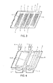
- Fig. 2 shows a first step in the method for manufacturing the flat pipe according to the embodiment.
- a metal thin plate 2 is punched out in an expanded shape of the flat pipe 1 (see Fig. 7 ) to provide incisions 3 with the expanded shape in the thin plate 2 such that the expanded shape of the flat pipe 1 has middle portions 4 (intermediate portions) widthwise of the expanded shape (laterally in Fig. 2 ; longitudinally of the thin plate 2) which are left uncut from the thin plate 2.
- metal material for the thin plate 2 is, for example, stainless steel or other ferrous material, non-ferrous metal material such as aluminum, copper or titanium, refractory metal material such as nickel, cobalt or molybdenum, low-melting-point metal material such as lead or tin, precious metal material such as gold, silver or platinum, or any alloy thereof.
- non-ferrous metal material such as aluminum, copper or titanium
- refractory metal material such as nickel, cobalt or molybdenum
- low-melting-point metal material such as lead or tin
- precious metal material such as gold, silver or platinum, or any alloy thereof.
- Fig. 3 shows a second step in the method for manufacturing the flat pipe according to the embodiment.
- the concave-convex shapes 5 on the inner and outer surfaces are machined in a range defined by the expanded shape of the flat pipe 1 (the range defined by the incisions 3) by press working.
- formed are, for example, the cylindrical pipe portions b, the swirling-flow-forming protrusions c and the like in the above-mentioned Fig. 1 .
- Fig. 4 shows a third step in the method for manufacturing the flat pipe according to the embodiment.
- upper and lower molds 6 and 7 are used to raise the expanded shape of the flat pipe 1 from the thin plate 2 with the uncut middle portion 4 in between (reference numeral 8 in Fig. 4 denotes cut-and-raised pieces from the thin plate 2).
- Fig. 4 Shown left and right in Fig. 4 are cases where the flat pipes 1 with elliptical and rectangular cross-sections are fabricated, respectively.
- Figs. 4ff. the concave-convex shapes 5 formed with respect to the previous Fig. 3 are not shown from a viewpoint of facilitated visualization.
- Fig. 5 shows a fourth step in the method for manufacturing the flat pipe according to the embodiment.
- upper and lower molds 9 and 10 are used to further raise the cut-and-raised pieces 8 from the thin plate 2 into uprightness.
- an upper mold 11 is used to fold tips of the cut-and-raised pieces 8 inward into co-closure, thereby forming the overall shape of the flat pipe 1.
- the flat pipe 1 is formed with one of lateral surfaces on the flat pipe 1 being left uncut from the thin plate 2 and with the other lateral surface being raised upward, the other lateral surface being formed by closing the tips of the cut-and-raised pieces 8 together inward.
- backing material complemental in shape to the upper mold 11 may be applied inside of the cut-and-raised pieces 8 raised to receive the upper mold 11.
- the upper mold 11 is used in the fifth step in Fig. 6 to fold the tips of the cut-and-raised pieces 8 inward into co-closure.
- Fig. 7 shows a sixth step in the method for manufacturing the flat pipe according to the embodiment.
- the uncut middle portions 4 (see Figs. 2-6 ) are separated off from the thin plate 2 to obtain the flat pipe 1.
- the joining may be made between the fifth and sixth steps before the uncut middle portions 4 are separated off from the thin plate 2; alternatively, the joining may be made after the sixth step and after the uncut middle portions 4 are separated off from the thin plate 2.
- selection may be appropriately made depending on easiness of a welding work.
- adhesive may be used, for example, especially when the metal material for the thin plate 2 is aluminum.
- welding is used for joining the joint including a base material through fusing, bearing in mind, for example, a fact that corrosive environment may be provided by a medium to be passed through the flat pipe 1.
- laser welding is preferable such as carbon dioxide laser welding, YAG laser welding or excimer laser welding.
- the closed tips of the cut-and-raised pieces 8 may be welded by butt welding or by lap welding.
- the closed tips of the cut-and-raised pieces 8 may be joined by brazing or soldering.
- the overall shape of the pipe requires to be accommodated in a heating chamber for heating, so that it is preferably conducted after the uncut middle portions 4 are separated off from the thin plate 2.
- Inner or/and outer surfaces of the flat pipe 1 separated off from the thin plate 2 may be machined to have surface finishing such as coating or plating, as need arises.
- the manufacturing method can be conducted stepwise in a manufacturing-line work with a blank being partly left uncut from and conveyed together with a thin plate 2 until the overall shape of the flat pipe 1 is formed, thereby substantially enhancing an efficiency of the manufacturing process.
- a number of joints to be joined is reduced to one, which can substantially reduce workload in the troublesome joint joining work.
- the manufacturing method can be conducted stepwise in a manufacturing-line work with a thin plate 2 being conveyed, thereby substantially enhancing an efficiency of the manufacturing method. This can substantially reduce the manufacturing cost in comparison with the conventional technique of manufacturing upper and lower halves of a flat pipe, respectively, and joining two joints on laterally opposite sides thereof, respectively.
- a method for manufacturing a flat pipe according to the invention is not limited to the above embodiment and that various changes and modifications may be made without departing from the scope of the invention.
- concave-convex shapes on inner and outer peripheries of a flat pipe are not restricted to those in the embodiment illustrated.
- portions to be left uncut from the thin plate are not always restricted to middle portions widthwise of a flat pipe and may be intermediate portions widthwise of the flat pipe.
Landscapes
- Engineering & Computer Science (AREA)
- Mechanical Engineering (AREA)
- Physics & Mathematics (AREA)
- Geometry (AREA)
- Thermal Sciences (AREA)
- General Engineering & Computer Science (AREA)
- Life Sciences & Earth Sciences (AREA)
- Forests & Forestry (AREA)
- Rigid Pipes And Flexible Pipes (AREA)
- Branch Pipes, Bends, And The Like (AREA)
- Bending Of Plates, Rods, And Pipes (AREA)
- Heat-Exchange Devices With Radiators And Conduit Assemblies (AREA)
Abstract
Description
- The present invention relates to a method for manufacturing a flat pipe.
- For example, in a shell-and-tube heat exchanger or the like, a plurality of heat-transfer pipes are carried in a shell such that a primary medium flowing through the pipes are heat-exchanged with a secondary medium flowing through the shell. It has been already proposed, for example, in undermentioned
Patent Literatures 1 and 2 that outer peripheries of the heat-transfer pipes are formed with spiral grooves which provide spiral protrusions, as inverse formations, on inner peripheries of the pipes to swirl the primary medium flowing through the pipes, thereby increasing contact frequency and contact distance of the primary medium to the inner peripheries of the pipes to enhance the heat exchange efficiency. - Such structure with the plural heat-transfer pipes in parallel with each other in the shell has a problem that the heat exchanger as a whole becomes large in structure due to lowness in heat exchange duty per unit volume and thus has deteriorated mountability to instrument/equipment. Thus, as exemplarily shown in
Fig. 1 , it has been started to study a flat pipe a shaped like cylindrical pipes arranged planarly and mutually proximately and connected together at mutually proximate portions thereof as communicating portions, cylindrical pipe portions b of the pipe a corresponding to the above-mentioned cylindrical pipes having inner peripheries formed with swirling-flow-forming protrusions c along spiral trajectories coaxial with central axes 0 of the portions b so that swirling flows of the medium d may be individually formed in the respective portions b (Japanese Patent Application No.2011-220778 -
- [Patent Literature 1]
JP 2000-345925A - [Patent Literature 2]
JP 2001-254649A - However, upon manufacturing of any flat pipe a with concave-convex shapes on inner and outer surfaces including the flat pipe a as mentioned in the above with respect to
Fig. 1 , it is difficult to form the flat pipe a without breaking down and/or distorting the concave-convex shapes. Thus, usually used for reliable manufacturing of this kind of flat pipe a is a technique of manufacturing upper and lower halves of the flat pipe a respectively which are then joined. Such technique provides two joints on laterally opposite sides of the flat pipe a, leading to a concern that manufacturing cost is substantially increased due to the two joints to be jointed, respectively, by welding or the like. - The invention was made in view of the above and has its object to provide a method for manufacturing a flat pipe capable of reducing a manufacturing cost more than ever before.
- The invention is directed to a method for manufacturing a flat pipe with concave-convex shapes on inner and outer surfaces, characterized in that it comprises making incisions, with an expanded shape of the flat pipe, in a metal thin plate such that intermediate portions in said expanded shape of the flat pipe widthwise of the expanded shape are left uncut from said thin plate, machining the concave-convex shapes in a range of said expanded shape of the flat pipe and raising said expanded shape of the flat pipe from said thin plate as cut-and-raised pieces with said uncut intermediate portions in between, closing tips of the cut-and-raised pieces together to form an overall shape of the flat pipe, and separating said uncut intermediate portions from said thin plate to obtain the flat pipe.
- In this way, the tips of the cut-and-raised pieces are closed together at a single joint, which halves the number of the joints in comparison with the conventional technique of manufacturing the upper and lower halves of the flat pipe, respectively, and joining the halves at two joints on laterally opposite sides thereof, respectively, leading to substantial reduction in workload in the troublesome joint joining work. Moreover, the manufacturing method can be conducted stepwise in a manufacturing-line work with a blank being partly left uncut from and conveyed together with a thin plate until the overall shape of the flat pipe is formed, thereby substantially enhancing an efficiency of the manufacturing process.
- In the invention, the closed tips of the cut-and-raised pieces may be joined before the uncut intermediate portions are separated off from the thin plate. Alternatively, the closed tips of the cut-and-raised pieces may be joined after the uncut intermediate portions are separated off from the thin plate.
- The method for manufacturing the flat pipe as mentioned in the above can exhibit excellent effects. A number of joints to be joined is reduced to one, which can substantially reduce workload in the troublesome joint joining work. Moreover, the manufacturing method can be conducted stepwise in a manufacturing-line work with a thin plate being conveyed, thereby substantially enhancing an efficiency of the manufacturing process. This can substantially reduce the manufacturing cost in comparison with the conventional technique of manufacturing upper and lower halves of a flat pipe, respectively, and joining two joints on laterally opposite sides thereof, respectively.
-
-
Fig. 1 is a perspective view showing an example of a flat pipe with concave-convex shapes on inner and outer surfaces; -
Fig. 2 is a perspective view schematically showing a first step in the embodiment of the invention; -
Fig. 3 is a perspective view schematically showing a second step in the embodiment of the invention; -
Fig. 4 is a perspective view schematically showing a third step in the embodiment of the invention; -
Fig. 5 is a perspective view schematically showing a fourth step in the embodiment of the invention; -
Fig. 6 is a perspective view schematically showing a fifth step in the embodiment of the invention; and -
Fig. 7 is a perspective view schematically showing a sixth step in the embodiment of the invention. - An embodiment of the invention will be described in conjunction with the drawings.
-
Figs. 2-7 show the embodiment of the invention schematically showing a method for manufacturing a flat pipe 1 with concave-convex shapes on inner and outer surfaces. Though the flat pipe 1 appears firstly inFig. 7 for a final step of the method, for explanation convenience the flat pipe is referred to together with its reference numeral early in description on initial steps while referring toFig. 7 . -
Fig. 2 shows a first step in the method for manufacturing the flat pipe according to the embodiment. In the first step, a metalthin plate 2 is punched out in an expanded shape of the flat pipe 1 (seeFig. 7 ) to provideincisions 3 with the expanded shape in thethin plate 2 such that the expanded shape of the flat pipe 1 has middle portions 4 (intermediate portions) widthwise of the expanded shape (laterally inFig. 2 ; longitudinally of the thin plate 2) which are left uncut from thethin plate 2. - Useable as the metal material for the
thin plate 2 is, for example, stainless steel or other ferrous material, non-ferrous metal material such as aluminum, copper or titanium, refractory metal material such as nickel, cobalt or molybdenum, low-melting-point metal material such as lead or tin, precious metal material such as gold, silver or platinum, or any alloy thereof. -
Fig. 3 shows a second step in the method for manufacturing the flat pipe according to the embodiment. In the second step, the concave-convex shapes 5 on the inner and outer surfaces are machined in a range defined by the expanded shape of the flat pipe 1 (the range defined by the incisions 3) by press working. Though roughly shown here, formed are, for example, the cylindrical pipe portions b, the swirling-flow-forming protrusions c and the like in the above-mentionedFig. 1 . -
Fig. 4 shows a third step in the method for manufacturing the flat pipe according to the embodiment. In the third step, upper andlower molds thin plate 2 with theuncut middle portion 4 in between (reference numeral 8 inFig. 4 denotes cut-and-raised pieces from the thin plate 2). - Shown left and right in
Fig. 4 are cases where the flat pipes 1 with elliptical and rectangular cross-sections are fabricated, respectively. In Figs. 4ff., the concave-convex shapes 5 formed with respect to the previousFig. 3 are not shown from a viewpoint of facilitated visualization. -
Fig. 5 shows a fourth step in the method for manufacturing the flat pipe according to the embodiment. In the fourth step, upper andlower molds pieces 8 from thethin plate 2 into uprightness. Then, in a fifth step shown inFig. 6 , anupper mold 11 is used to fold tips of the cut-and-raisedpieces 8 inward into co-closure, thereby forming the overall shape of the flat pipe 1. - Specifically, in the embodiment illustrated, the flat pipe 1 is formed with one of lateral surfaces on the flat pipe 1 being left uncut from the
thin plate 2 and with the other lateral surface being raised upward, the other lateral surface being formed by closing the tips of the cut-and-raisedpieces 8 together inward. - When portions of the flat pipe 1 pushed by the
molds Figs. 4 and5 are also desired to have concave-convex shapes, it is possible to make themolds Fig. 3 ) are applied upon raising of the cut-and-raisedpieces 8 from thethin plate 2. - Upon using the
upper mold 11 to fold the tips of the cut-and-raisedpieces 8 inward into co-closure in the fifth step inFig. 6 , backing material (not shown) complemental in shape to theupper mold 11 may be applied inside of the cut-and-raisedpieces 8 raised to receive theupper mold 11. - In the description on the embodiment, the
upper mold 11 is used in the fifth step inFig. 6 to fold the tips of the cut-and-raisedpieces 8 inward into co-closure. Alternatively, it is possible, for example, to preliminarily fold the tips of the cut-and-raisedpieces 8 in the third step inFig. 4 so that when the cut-and-raisedpieces 8 are further raised into uprightness in the fourth step inFig. 5 , the tips of the cut-and-raisedpieces 8 are closed together. -
Fig. 7 shows a sixth step in the method for manufacturing the flat pipe according to the embodiment. In the sixth step, the uncut middle portions 4 (seeFigs. 2-6 ) are separated off from thethin plate 2 to obtain the flat pipe 1. With respect to the closed tips of the cut-and-raisedpieces 8, the joining may be made between the fifth and sixth steps before theuncut middle portions 4 are separated off from thethin plate 2; alternatively, the joining may be made after the sixth step and after theuncut middle portions 4 are separated off from thethin plate 2. As to at what timing the joining is to be conducted, selection may be appropriately made depending on easiness of a welding work. - In this occasion, for the joining of the closed tips of the cut-and-raised
pieces 8, adhesive may be used, for example, especially when the metal material for thethin plate 2 is aluminum. However, preferably, welding is used for joining the joint including a base material through fusing, bearing in mind, for example, a fact that corrosive environment may be provided by a medium to be passed through the flat pipe 1. More specifically, laser welding is preferable such as carbon dioxide laser welding, YAG laser welding or excimer laser welding. The closed tips of the cut-and-raisedpieces 8 may be welded by butt welding or by lap welding. - Alternatively, the closed tips of the cut-and-raised
pieces 8 may be joined by brazing or soldering. In such occasion, the overall shape of the pipe requires to be accommodated in a heating chamber for heating, so that it is preferably conducted after the uncutmiddle portions 4 are separated off from thethin plate 2. - Inner or/and outer surfaces of the flat pipe 1 separated off from the
thin plate 2 may be machined to have surface finishing such as coating or plating, as need arises. - In this way, the tips of the cut-and-raised
pieces 8 are closed together at a single joint, which halves the number of the joints in comparison with the conventional technique of manufacturing the upper and lower halves of the flat pipe 1, respectively, and joining the halves at two joints on laterally opposite sides thereof, respectively, leading to substantial reduction in workload in the troublesome joint joining work. Moreover, the manufacturing method can be conducted stepwise in a manufacturing-line work with a blank being partly left uncut from and conveyed together with athin plate 2 until the overall shape of the flat pipe 1 is formed, thereby substantially enhancing an efficiency of the manufacturing process. - Thus, according to the above-mentioned embodiment, a number of joints to be joined is reduced to one, which can substantially reduce workload in the troublesome joint joining work. Moreover, the manufacturing method can be conducted stepwise in a manufacturing-line work with a
thin plate 2 being conveyed, thereby substantially enhancing an efficiency of the manufacturing method. This can substantially reduce the manufacturing cost in comparison with the conventional technique of manufacturing upper and lower halves of a flat pipe, respectively, and joining two joints on laterally opposite sides thereof, respectively. - It is to be understood that a method for manufacturing a flat pipe according to the invention is not limited to the above embodiment and that various changes and modifications may be made without departing from the scope of the invention. For example, concave-convex shapes on inner and outer peripheries of a flat pipe are not restricted to those in the embodiment illustrated. Moreover, upon making incisions with a expanded shape of the flat pipe in a metal thin plate, portions to be left uncut from the thin plate are not always restricted to middle portions widthwise of a flat pipe and may be intermediate portions widthwise of the flat pipe.
-
- 1
- flat pipe
- 2
- thin plate
- 3
- incision
- 4
- middle portion (intermediate portion)
- 5
- concave-convex shape
- 8
- cut-and-raised piece
Claims (3)
- A method for manufacturing a flat pipe with concave-convex shapes on inner and outer surfaces, which comprises making incisions, with an expanded shape of the flat pipe, in a metal thin plate such that intermediate portions in said expanded shape of the flat pipe widthwise of the expanded shape are left uncut from said thin plate, machining the concave-convex shapes in a range of said expanded shape of the flat pipe and raising said expanded shape of the flat pipe from said thin plate as cut-and-raised pieces with said uncut intermediate portions in between, closing tips of the cut-and-raised pieces together to form an overall shape of the flat pipe, and separating said uncut intermediate portions from said thin plate to obtain the flat pipe.
- The method for manufacturing the flat pipe as claimed in claim 1, wherein the closed tips of the cut-and-raised pieces are joined before the uncut intermediate portions are separated off from the thin plate.
- The method for manufacturing the flat pipe as claimed in claim 1, wherein the closed tips of the cut-and-raised pieces are joined after the uncut intermediate portions are separated off from the thin plate.
Applications Claiming Priority (2)
| Application Number | Priority Date | Filing Date | Title |
|---|---|---|---|
| JP2012237552A JP6067327B2 (en) | 2012-10-29 | 2012-10-29 | Flat tube manufacturing method |
| PCT/JP2013/006316 WO2014068926A1 (en) | 2012-10-29 | 2013-10-24 | Method for manufacturing flat pipe |
Publications (2)
| Publication Number | Publication Date |
|---|---|
| EP2913118A1 true EP2913118A1 (en) | 2015-09-02 |
| EP2913118A4 EP2913118A4 (en) | 2016-06-08 |
Family
ID=50626876
Family Applications (1)
| Application Number | Title | Priority Date | Filing Date |
|---|---|---|---|
| EP13850999.7A Withdrawn EP2913118A4 (en) | 2012-10-29 | 2013-10-24 | Method for manufacturing flat pipe |
Country Status (5)
| Country | Link |
|---|---|
| US (1) | US9403201B2 (en) |
| EP (1) | EP2913118A4 (en) |
| JP (1) | JP6067327B2 (en) |
| CN (2) | CN104755190A (en) |
| WO (1) | WO2014068926A1 (en) |
Families Citing this family (1)
| Publication number | Priority date | Publication date | Assignee | Title |
|---|---|---|---|---|
| DE102014102974A1 (en) * | 2014-03-06 | 2015-09-10 | Thyssenkrupp Steel Europe Ag | Method for customizing the shape of components |
Family Cites Families (14)
| Publication number | Priority date | Publication date | Assignee | Title |
|---|---|---|---|---|
| US5243842A (en) * | 1988-07-14 | 1993-09-14 | Showa Aluminum Kabushiki Kaisha | Method of making a brazeable metal pipe having tube-insertion apertures formed with guide lugs |
| US4971239A (en) * | 1988-12-21 | 1990-11-20 | Ameron, Inc. | Method and apparatus for making welded tapered tubes |
| AU650221B2 (en) * | 1989-08-25 | 1994-06-09 | Showa Denko Kabushiki Kaisha | A method of making a brazeable metal pipe having tube-insertion apertures formed with guide lugs |
| US5119552A (en) * | 1990-02-16 | 1992-06-09 | Sanden Corporation | Method for manufacturing header pipe of heat exchanger |
| JP3114918B2 (en) * | 1995-12-01 | 2000-12-04 | トヨタ自動車株式会社 | Manufacturing method of curved hollow pipe |
| JP3459924B2 (en) * | 1996-10-15 | 2003-10-27 | 株式会社マルナカ | Tube for heat exchanger and method for producing the same |
| JP3212268B2 (en) * | 1997-08-08 | 2001-09-25 | 株式会社ゼクセルヴァレオクライメートコントロール | Tube for heat exchanger and method for producing the same |
| JP2000345925A (en) | 1999-06-04 | 2000-12-12 | Hino Motors Ltd | EGR cooler |
| EP1121993B1 (en) * | 2000-02-04 | 2014-01-08 | Ricoh Company, Ltd. | Pipe body and forming method of the same |
| JP2001254649A (en) | 2000-03-13 | 2001-09-21 | Hino Motors Ltd | EGR cooler |
| JP2003136142A (en) * | 2001-10-31 | 2003-05-14 | Terumo Corp | Metallic tubular member and method for manufacturing metallic tubular member |
| CN100402182C (en) * | 2002-10-30 | 2008-07-16 | 昭和电工株式会社 | Method and device for producing semifinished flat tubes |
| JP5578918B2 (en) | 2010-04-07 | 2014-08-27 | 矢崎総業株式会社 | Light guide plate and pointer instrument having the same |
| CN102179697B (en) * | 2011-03-25 | 2012-12-12 | 无锡凯博易机电科技有限公司 | Roll bending formation manufacturing method and equipment for porous microchannel flat pipe |
-
2012
- 2012-10-29 JP JP2012237552A patent/JP6067327B2/en active Active
-
2013
- 2013-10-24 CN CN201380056730.7A patent/CN104755190A/en active Pending
- 2013-10-24 CN CN201910126739.XA patent/CN110000237A/en active Pending
- 2013-10-24 WO PCT/JP2013/006316 patent/WO2014068926A1/en not_active Ceased
- 2013-10-24 US US14/413,271 patent/US9403201B2/en not_active Expired - Fee Related
- 2013-10-24 EP EP13850999.7A patent/EP2913118A4/en not_active Withdrawn
Also Published As
| Publication number | Publication date |
|---|---|
| US9403201B2 (en) | 2016-08-02 |
| JP2014087804A (en) | 2014-05-15 |
| JP6067327B2 (en) | 2017-01-25 |
| CN104755190A (en) | 2015-07-01 |
| WO2014068926A1 (en) | 2014-05-08 |
| US20150135795A1 (en) | 2015-05-21 |
| CN110000237A (en) | 2019-07-12 |
| EP2913118A4 (en) | 2016-06-08 |
Similar Documents
| Publication | Publication Date | Title |
|---|---|---|
| CN103402669B (en) | Forging method | |
| JP5628863B2 (en) | Pre-formed products used in the manufacture of shell-tube type heat exchangers | |
| CN109073325B (en) | Heat exchanger plate, plate heat exchanger and method of making a plate heat exchanger | |
| WO2009104575A1 (en) | Method of manufacturing a pipe coupling component, method of manufacturing a casing structural member, and pipe coupling structure for a hollow part | |
| CN106794506B (en) | The method for manufacturing turbine components ring supporting element | |
| CN102126107A (en) | Forging process of forged rings | |
| JP2014104502A (en) | Manufacturing method of structure of dissimilar joint body and manufacturing method of dissimilar joint body | |
| CN103624354B (en) | The plug-in type welding method of a kind of metal compaction pipe and metal perforated pipe | |
| CN109477703A (en) | Laminated header and method of manufacturing the stacked header | |
| TWI558484B (en) | Method for splitting inside edge section of metal plate or metal rod, and method for manufacturing metal containers and metal tubes and method for bonding metal parts using such inside splitting method | |
| US9403201B2 (en) | Method for manufacturing flat pipe | |
| JP6944470B2 (en) | How to process flat holes with burring on metal plates | |
| JP4973275B2 (en) | Manufacturing method of pipe joint | |
| EP4056294B1 (en) | Method for manufacturing double-pipe heat exchanger | |
| CN201982623U (en) | Brazing input bracket for powder metallurgy | |
| US11156413B2 (en) | Metal plate burring method | |
| JP2018094565A (en) | Manufacturing method of seamless metallic pipe | |
| CN104833092B (en) | A kind of enamel inner container and its manufacture craft | |
| JP2004324937A (en) | Header structure for heat exchanger | |
| KR20100084862A (en) | Method for manufacturing the annular cooling gallery of a piston of internal combustion engine | |
| JP2009014213A (en) | Shear surface coating process for clad member | |
| JP2011121084A (en) | Tubular material jointer and tubular material joining method | |
| JPS5881558A (en) | Connecting method of tube and end plate in heat exchanger | |
| CN101846209A (en) | Friction welding petroleum machinery valve with composite structure and forging/welding method | |
| KR100254591B1 (en) | Manufacturing method of soldering metal pipe having guide member in tube insertion hole |
Legal Events
| Date | Code | Title | Description |
|---|---|---|---|
| PUAI | Public reference made under article 153(3) epc to a published international application that has entered the european phase |
Free format text: ORIGINAL CODE: 0009012 |
|
| 17P | Request for examination filed |
Effective date: 20150225 |
|
| AK | Designated contracting states |
Kind code of ref document: A1 Designated state(s): AL AT BE BG CH CY CZ DE DK EE ES FI FR GB GR HR HU IE IS IT LI LT LU LV MC MK MT NL NO PL PT RO RS SE SI SK SM TR |
|
| AX | Request for extension of the european patent |
Extension state: BA ME |
|
| DAX | Request for extension of the european patent (deleted) | ||
| RA4 | Supplementary search report drawn up and despatched (corrected) |
Effective date: 20160509 |
|
| RIC1 | Information provided on ipc code assigned before grant |
Ipc: B21D 5/01 20060101ALI20160502BHEP Ipc: F28F 1/02 20060101ALI20160502BHEP Ipc: F28F 1/42 20060101ALI20160502BHEP Ipc: B21D 53/02 20060101AFI20160502BHEP |
|
| 17Q | First examination report despatched |
Effective date: 20190314 |
|
| GRAP | Despatch of communication of intention to grant a patent |
Free format text: ORIGINAL CODE: EPIDOSNIGR1 |
|
| INTG | Intention to grant announced |
Effective date: 20200108 |
|
| STAA | Information on the status of an ep patent application or granted ep patent |
Free format text: STATUS: THE APPLICATION IS DEEMED TO BE WITHDRAWN |
|
| 18D | Application deemed to be withdrawn |
Effective date: 20200603 |