EP2912150B1 - Method and apparatus for pelletizing blends of biomass materials for use as fuel - Google Patents
Method and apparatus for pelletizing blends of biomass materials for use as fuel Download PDFInfo
- Publication number
- EP2912150B1 EP2912150B1 EP13848257.5A EP13848257A EP2912150B1 EP 2912150 B1 EP2912150 B1 EP 2912150B1 EP 13848257 A EP13848257 A EP 13848257A EP 2912150 B1 EP2912150 B1 EP 2912150B1
- Authority
- EP
- European Patent Office
- Prior art keywords
- drum
- assembly
- cooling
- biomass
- dryer
- Prior art date
- Legal status (The legal status is an assumption and is not a legal conclusion. Google has not performed a legal analysis and makes no representation as to the accuracy of the status listed.)
- Not-in-force
Links
Images




Classifications
-
- C—CHEMISTRY; METALLURGY
- C10—PETROLEUM, GAS OR COKE INDUSTRIES; TECHNICAL GASES CONTAINING CARBON MONOXIDE; FUELS; LUBRICANTS; PEAT
- C10L—FUELS NOT OTHERWISE PROVIDED FOR; NATURAL GAS; SYNTHETIC NATURAL GAS OBTAINED BY PROCESSES NOT COVERED BY SUBCLASSES C10G OR C10K; LIQUIFIED PETROLEUM GAS; USE OF ADDITIVES TO FUELS OR FIRES; FIRE-LIGHTERS
- C10L9/00—Treating solid fuels to improve their combustion
- C10L9/08—Treating solid fuels to improve their combustion by heat treatments, e.g. calcining
- C10L9/083—Torrefaction
-
- C—CHEMISTRY; METALLURGY
- C10—PETROLEUM, GAS OR COKE INDUSTRIES; TECHNICAL GASES CONTAINING CARBON MONOXIDE; FUELS; LUBRICANTS; PEAT
- C10L—FUELS NOT OTHERWISE PROVIDED FOR; NATURAL GAS; SYNTHETIC NATURAL GAS OBTAINED BY PROCESSES NOT COVERED BY SUBCLASSES C10G OR C10K; LIQUIFIED PETROLEUM GAS; USE OF ADDITIVES TO FUELS OR FIRES; FIRE-LIGHTERS
- C10L5/00—Solid fuels
- C10L5/02—Solid fuels such as briquettes consisting mainly of carbonaceous materials of mineral or non-mineral origin
- C10L5/34—Other details of the shaped fuels, e.g. briquettes
- C10L5/36—Shape
- C10L5/363—Pellets or granulates
-
- C—CHEMISTRY; METALLURGY
- C10—PETROLEUM, GAS OR COKE INDUSTRIES; TECHNICAL GASES CONTAINING CARBON MONOXIDE; FUELS; LUBRICANTS; PEAT
- C10L—FUELS NOT OTHERWISE PROVIDED FOR; NATURAL GAS; SYNTHETIC NATURAL GAS OBTAINED BY PROCESSES NOT COVERED BY SUBCLASSES C10G OR C10K; LIQUIFIED PETROLEUM GAS; USE OF ADDITIVES TO FUELS OR FIRES; FIRE-LIGHTERS
- C10L5/00—Solid fuels
- C10L5/40—Solid fuels essentially based on materials of non-mineral origin
- C10L5/44—Solid fuels essentially based on materials of non-mineral origin on vegetable substances
-
- Y—GENERAL TAGGING OF NEW TECHNOLOGICAL DEVELOPMENTS; GENERAL TAGGING OF CROSS-SECTIONAL TECHNOLOGIES SPANNING OVER SEVERAL SECTIONS OF THE IPC; TECHNICAL SUBJECTS COVERED BY FORMER USPC CROSS-REFERENCE ART COLLECTIONS [XRACs] AND DIGESTS
- Y02—TECHNOLOGIES OR APPLICATIONS FOR MITIGATION OR ADAPTATION AGAINST CLIMATE CHANGE
- Y02E—REDUCTION OF GREENHOUSE GAS [GHG] EMISSIONS, RELATED TO ENERGY GENERATION, TRANSMISSION OR DISTRIBUTION
- Y02E50/00—Technologies for the production of fuel of non-fossil origin
- Y02E50/10—Biofuels, e.g. bio-diesel
-
- Y—GENERAL TAGGING OF NEW TECHNOLOGICAL DEVELOPMENTS; GENERAL TAGGING OF CROSS-SECTIONAL TECHNOLOGIES SPANNING OVER SEVERAL SECTIONS OF THE IPC; TECHNICAL SUBJECTS COVERED BY FORMER USPC CROSS-REFERENCE ART COLLECTIONS [XRACs] AND DIGESTS
- Y02—TECHNOLOGIES OR APPLICATIONS FOR MITIGATION OR ADAPTATION AGAINST CLIMATE CHANGE
- Y02E—REDUCTION OF GREENHOUSE GAS [GHG] EMISSIONS, RELATED TO ENERGY GENERATION, TRANSMISSION OR DISTRIBUTION
- Y02E50/00—Technologies for the production of fuel of non-fossil origin
- Y02E50/30—Fuel from waste, e.g. synthetic alcohol or diesel
Definitions
- the present invention relates generally to an assembly of components that may be employed to process biomass materials for use as fuel. More particularly, the invention relates to a method and apparatus for blending torrefied biomass with white biomass for subsequent pelletization.
- biomass materials are generally comprised of cellulose, hemicellulose and lignin.
- category of biomass generally known as "wood” is comprised of approximately 1/3 by weight cellulose, approximately 1/3 by weight hemicellulose and approximately 1/3 by weight lignin.
- wood waste from construction and demolition activities C&D materials
- C&D materials wood waste from construction and demolition activities
- Green or unprocessed biomass is low in sulfur but has a relatively high moisture content and a relatively low heating value per unit of weight, when compared to coal, for example. Consequently, in order to create an efficient biomass - to - energy conversion, it is known to dry biomass materials and/or to torrefy biomass materials for subsequent densification. Drying of biomass materials will generally reduce the moisture content from 30-50% by weight in the green state (15-25% for C&D materials) to about 5-12% by weight, and it will increase the heating value per unit of weight because of the loss of moisture weight. However, drying will not impart significant chemical changes to the biomass materials.
- torrefaction which may be generally described as a pyrolysis or thermal degradation process carried out on wood or other biomass materials at temperatures typically less than 315°C (about 600° F) in a low-oxygen atmosphere.
- VOCs volatile organic compounds
- the removal of hemicellulose increases the energy density or heating value per unit of weight of the biomass; however, full torrefaction without recovery of the evaporated volatile organic compounds results in the loss of the energy stored therein.
- US2010/242351 A1 discloses an apparatus for processing green biomass material by torrefaction.
- the apparatus includes a dryer for reducing the moisture content of the biomass material; a torrefaction reactor for processing the dried biomass material; a burner; a heat exchanger; and lines for conveying heated thermal fluid from the heat exchanger to the dryer and the torrefaction reactor.
- the torrefied biomass is processed through a cooler prior to densification.
- a pelletized form of dried or torrefied wood or biomass is highly desirable in that it would allow easy and relatively clean handling and more efficient shipment, especially ocean freight shipment, of a biomass-based fuel. It is known to make fuel pellets from dried wood, and many attempts have been made to form fuel pellets of torrefied wood and biomass. However, the inventors have found that blends of dried and torrefied biomass materials can be pelletized to produce stable pellets of high durability. Furthermore, the inventors have devised a process that employs parallel processing of dried and torrefied biomass in such a way as to increase the energy efficiency of the process.
- the present invention provides a method and apparatus for making stable fuel pellets from blends of dried and torrefied biomass materials.
- Another advantage of the invention is that it may be employed to produce a fuel pellet from such blends that has heating values similar to that of coal, as well as high grindability, structural stability, and moisture resistance.
- the preferred apparatus used in processing the dried and torrefied biomass materials uses energy produced or released in the processing of biomass materials and consequently minimizes the need for added sources of energy.
- green biomass and “green biomass materials” refer to biomass materials that have been processed to reduce their particle size.
- green wood chips refers to materials obtained from trees and other woody plants that have been processed to reduce their particle size.
- construction and demolition materials and “C&D materials” refer to wood products of various types and forms that have been obtained from construction and/or demolition projects.
- C&D chips refers to C&D material that has been processed to reduce its particle size to approximately 1.27cm (1 ⁇ 2 inch) or less.
- green wood refers to green wood chips and/or C&D chips that have been processed to reduce their particle size to approximately 1.27cm (1 ⁇ 2 inch) or less.
- wood chips includes green wood chips and C&D chips.
- white biomass and “white biomass materials” refer to green biomass materials that have been dried to increase their heating value per unit of weight.
- white wood refers to green wood that has been processed to increase its heating value per unit of weight, but not above 20701 KJ/kg (8900 BTU/lb).
- biomass and “torrefied biomass materials” refer to biomass materials that have been processed to increase their heating value per unit of weight by breaking down the hemicellulose in the biomass into volatile organic compounds.
- torrefied wood refers to biomass comprising wood chips that have been processed to increase their heating value per unit of weight by breaking down the hemicellulose in the biomass into volatile organic compounds.
- lightly torrefied wood and similar terms refer to biomass comprising wood chips that have been processed in a torrefaction process to increase their heating value to a level within the range of about 20701 KJ/kg (8900 BTU/lb) to about 22097 KJ/kg (9500 BTU/lb ) .
- the term "fully torrefied wood” and similar terms refer to biomass comprising wood chips that have been processed in a torrefaction process to increase their heating value to a level within the range of about 22097 KJ/kg (9500 BTU/lb) to about 27912 KJ/kg (12000 BTU/lb).
- an assembly for processing green biomass materials from two separate feed sources for use as a fuel pellet comprising: (A) a drying assembly for converting green biomass material from a first source to white biomass material; the white biomass material being green biomass material that has been dried to increase its heating value per unit of weight; (B) a torrefaction assembly for converting green biomass material from a second source to torrefied biomass material; (C) a heating assembly comprising: (1) a heat exchanger having a plurality of heat transfer coils (32) therein containing a thermal fluid; (2) a burner for heating the thermal fluid in the heat transfer coils to a temperature within the range of about 93° C (200°F) to about 288°C (550°F), said burner also producing flue gases; (3) means for conveying heated thermal fluid from the heat exchanger to the drying assembly; (4) means for conveying heated thermal fluid from the heat exchanger to the torrefaction assembly; and (D) a pellet press for pelletizing a blend of biomass
- the invention comprises a method and apparatus for processing green biomass materials for pelletizing into a fuel pellet. More particularly, the invention comprises a pair of parallel processing systems for preparing white biomass materials and torrefied biomass materials for blending prior to pelletizing.
- a preferred embodiment of the white biomass preparation system includes a predryer, a biomass dryer and a hammermill, and a preferred embodiment of the torrefied biomass preparation system includes a torrefaction reactor, a spray cooler and a hammermill.
- Heat is supplied to both systems by a heating assembly which includes a burner, a heat exchanger having a plurality of heat transfer coils therein and a combustion chamber that is operatively connected between the burner and the heat exchanger.
- the heating assembly is configured and arranged so that the burner may be operated to heat a thermal fluid in the heat transfer coils to a temperature of up to about 288 °C (550°F).
- the torrefied biomass preparation system will operate in such a way that volatile organic compounds are stripped from the off gases of the torrefaction reactor.
- a fuel control mechanism that is a part of the heating assembly may be operated to control the supply of external fuel to the burner at a first rate when the assembly is first placed into operation. Then, as volatile organic compounds are stripped from the biomass materials in the torrefaction reactor and are conveyed to the combustion chamber, the rate of supply of external fuel to the burner may be reduced to a second rate that is lower than the first rate.
- the supply of external fuel to the burner may be shut off and continued heat supplied to the combustion chamber by the incineration of volatile organic compounds therein.
- the drawings illustrate preferred embodiments of a plant for producing fuel pellets from blends of white and torrefied biomass materials.
- Parallel processing streams are shown therein, one for the preparation of white biomass material that is supplied from a first feed stream and the other for the preparation of torrefied biomass material that is supplied from a second feed stream.
- the feed material for the white biomass preparation system has a higher moisture content than that for the torrefied biomass preparation system.
- the embodiment of the invention illustrated in the drawings may be operated to prepare white wood from a first source S1 of green wood chips having a moisture content of about 30-50% by weight, while simultaneously preparing torrefied wood from a second source S2 of C&D chips having a moisture content of about 15-25% by weight. Subsequently, the white wood and the torrefied wood may be blended together for use in producing fuel pellets.
- the preferred white biomass preparation system includes predryer 15, biomass dryer 16 and first hammermill 17, and the preferred torrefied biomass preparation system includes torrefaction reactor 18, spray cooler 19 and second hammermill 20.
- Heat is supplied to both systems by heating assembly 21 which includes burner 22, heat exchanger 26 (identified as thermal oil heater in Figure 1 ) having a plurality of heat transfer coils 32 therein, and combustion chamber 24 that is operatively connected between the burner and the heat exchanger.
- the heating assembly is configured and arranged so that the burner may be operated to heat a thermal fluid in the heat transfer coils to a temperature of up to about 288°C (550°F).
- Burner 22 is of a conventional type having air inlet 28 and is adapted to burn fuel such as natural gas, propane, pulverized coal, fuel oil or the like. As best shown in Figure 2 , burner 22 produces flame 30 in combustion chamber 24, heating air that passes into heat exchanger 26. Heat exchanger 26 includes a plurality of heat transfer coils 32 therein, which coils are adapted to receive a thermal fluid such as thermal oil. Combustion chamber 24 is operatively connected between the burner and the heat exchanger so that air heated in the combustion chamber by the burner may be conveyed into the heat exchanger, where it will heat the thermal fluid in heat transfer coils 32.
- Heat exchanger 26 is equipped with a recirculation fan (not shown) that is mounted in housing 34 and operates to draw heated air from heat exchanger 26 through recirculation duct 36 and into combustion chamber 24 for further heating. Heat exchanger 26 also includes exhaust stack 38. Preferably, the heating assembly will be operated to generate up to 21100 MJ (20 million BTUs) per hour to heat the thermal fluid within heat transfer coils 32 to a temperature of up to about 288°C (550° F).
- Thermal fluid within heat transfer coils 32 is conveyed to biomass dryer 16 and torrefaction reactor 18 in a fluid circuit to be described hereinafter.
- the heating assembly includes controls such as are known to those having ordinary skill in the art to control the rate of flow of thermal fluid to the biomass dryer and the rate of flow of thermal fluid to the torrefaction reactor. In the preferred embodiment of the invention, these controls are operated, and the rotation and feed of material into the biomass dryer and the torrefaction reactor are controlled, to insure that the thermal fluid in the biomass dryer will heat green biomass material therein (or pre-dried biomass material, as described hereinafter) to a temperature within the range of 200°F.
- the preferred heating assembly is the ConvectecTM heater that is manufactured and sold by Heatec, Inc. of Chattanooga, Tennessee.
- Biomass dryer 16 includes dryer frame 42 (shown in Figures 3-5 ) having upper end 44 and lower end 46.
- Generally cylindrical dryer drum 48 is mounted on dryer frame 42 for rotation about axis 50 (best shown in Figure 4 ).
- Dryer drum 48 includes a pair of outer rings 52 that engage trunnions 54 on dryer frame 42.
- a motor (not shown) is adapted to rotatably drive a sprocket (not shown, but located in housing 58) that is in driving engagement with drive chain 60 which engages sprocket 62 mounted on the outer surface of the drum to rotate dryer drum 48 in a conventional manner.
- Alternative drive systems such as are known to those having ordinary skill in the art to which the invention relates may also be employed to rotate dryer drum 48 with respect to dryer frame 42.
- dryer drum 48 is mounted on frame 42 having upper end 44 and lower end 46, the axis 50 of the drum is oriented downwardly from upper end 64 of dryer drum 48 to lower end 66 of the drum (best shown in Figure 5 ).
- Upper end 64 of dryer drum 48 is provided with inlet 68 for green wood, and lower end 66 is provided with a discharge outlet in the form of chute 70 (best shown in Figures 5 and 6 ).
- Dryer drum 48 is also provided with a plurality of thermal fluid tubes 72 that extend along the interior of the drum and are adapted to circulate thermal fluid that has been heated by the heating assembly.
- heated fluid passes out of thermal fluid outlet 73 of heat exchanger 26 of heating assembly 21 to and through thermal fluid tubes 72 of dryer drum 48 and back into the heat exchanger through thermal fluid inlet 74 (see Figure 2 ). Since axis 50 of dryer drum 48 is tilted with respect to the ground on which frame 42 is placed, rotation of the dryer drum will cause green wood introduced into inlet 68 at upper end 64 to tumble and move downwardly towards discharge outlet 70 at lower end 66. As it does so, the green wood will come into contact with thermal fluid tubes 72 multiple times. Because there may be expansion of the thermal fluid as it is heated, an expansion tank 75 (see Figures 1 and 3 ) and an associated pump is provided to withdraw hot thermal fluid from the expansion tank and return it to the thermal fluid circuit as needed.
- the thermal fluid tubes of dryer drum 48 are mounted through and supported by a plurality of tube support plates 150 that are spaced along the length of the dryer drum. These support plates include a plurality of tube support holes 152 that support thermal fluid tubes near the periphery of the dryer drum. Support plates 150 also support a plurality of flights or scoops 156 in the central portion of the dryer drum. These scoops 156 capture biomass material that has spilled out of the tube bundle into the central portion of the drum, and they direct such material back into contact with the thermal fluid tubes.
- the thermal fluid tubes are in fluid communication with a thermal fluid manifold 158 that is supported in manifold support holes 160 in support plates 150, so that thermal fluid can be circulated through the various fluid tubes of the drying assembly.
- the heated thermal fluid be pumped into and through thermal fluid tubes 72 while the dryer drum is rotated at a rate sufficient to convey the green wood introduced into the inlet thereof to the discharge outlet of the dryer drum as it is heated to a temperature of at least about 93°C (200°F).
- the dryer drum is of sufficient size and capacity, and is adapted to be rotated at a rate that will provide 40-50 minutes of residence time for biomass material therein.
- the heating assembly includes a recirculation system for recirculating hot, low-oxygen gases from exhaust stack 38 of the heat exchanger to the dryer drum in order to lower the humidity within the dryer drum.
- this recirculation system includes outlet line 77 from the heat exchanger, recirculating fan 78 and inlet line 79 to dryer drum 48.
- steam will be produced as the moisture content of the green wood is reduced. This steam will displace air in the drying drum until the oxygen content in the atmosphere of the drum is reduced to below about 9%, and more preferably below about 6%.
- Steam duct 80 is provided for conveying steam from upper end 64 of dryer drum 48 to combustion chamber 24 of heating assembly 21.
- predryer 15 is provided to utilize heat from the flue gases passing through exhaust stack 38 of heat exchanger 26 to preheat green biomass material prior to its introduction into biomass dryer 16. Once the plant is placed into operation, green biomass materials can be introduced into the predryer.
- predryer 15 comprises an inclined rotating predryer drum 162.
- the predryer drum is mounted on frame 164 and includes upper end 166 and lower end 168.
- a rotation system for rotating the predryer drum about its long axis 170 includes a pair of outer rings 172 that engage trunnions 174 on frame 164.
- Motor 176 is adapted to rotatably drive a sprocket (not shown, but similar to that of dryer drum 48) that is in driving engagement with a drive chain (also not shown) which engages sprocket 178 mounted on the outer surface of the drum to rotate predryer drum 162 in a conventional manner.
- Hopper 180 is located at upper end 166 of predryer drum 162 and is in communication with inlet chute 182.
- the hopper is adapted to receive green biomass materials from conveyor 183 (shown in Figure 1 ). This green biomass material is pre-dried in the predryer to remove a portion of the moisture contained therein and to raise the temperature of the biomass material.
- An auger or screw conveyor 184 is preferably located in inlet chute 182 to convey green biomass material from the hopper into predryer drum 162.
- Inlet line 186 for exhaust gases from heat exchanger 26 is also located on the upper end 166 of predryer drum 162.
- hot flue gases from the heat exchanger are directed from exhaust stack 38 through pipe 163 (shown in phantom in Figure 6 ) and inlet line 186 into the predryer drum so as to flow therethrough parallel to the flow of biomass.
- Pre-dried biomass is discharged from the lower end 168 of the predryer drum through outlet chute 188 onto conveyor 190 that transports the pre-dried biomass to dryer drum 48 of biomass dryer 16.
- the pre-dried biomass from the outlet chute of the predryer drum is conveyed to inlet 68 of dryer drum 48.
- the dryer drum may be rotated at a rate sufficient to convey the pre-dried biomass introduced into the inlet of the dryer drum to the discharge outlet of the dryer drum as it is heated to a temperature sufficient to convert the pre-dried biomass into white wood having a heating value of up to about 20701 KJ/kg (8900BTU/lb).
- the white wood preparation system may be operated to heat biomass materials in the biomass dryer to a temperature within the range of about 182°C (350°F) to about 232°C (450°F) to produce lightly torrefied biomass having a heating value within the range of about 20701 KJ/kg ( 8900 BTU/lb) to about 22097 KJ/kg (9500 BTU/lb).
- This light torrefaction process results in the generation of a small amount of volatile organic compounds (VOCs) in the dryer drum; however, the predryer captures excess heat from the hot flue gasses produced in heat exchanger 26 and transfers a portion of this excess heat to the green biomass material in the predrying process, thereby increasing the thermal efficiency of the white wood system.
- VOCs volatile organic compounds
- the preferred torrefied wood system includes torrefaction reactor 18, spray cooler 19 and second hammermill 20.
- a second predryer (not shown) may also be provided upstream of the torrefaction reactor.
- Torrefaction reactor 18 is essentially the same as biomass dryer 16, although the torrefied wood system is operated to heat the green biomass material in the torrefaction reactor to a temperature of at least about 246°C (475 °F) to convert it to torrefied biomass.
- Torrefaction reactor 18 includes reactor frame 130 (shown in Figures 10 and 11 ) having upper end 131 and lower end 132.
- Generally cylindrical reactor drum 133 is mounted on reactor frame 130 for rotation about axis 134 (best shown in Figure 10 ).
- Reactor drum 133 includes a pair of outer rings 135 that engage trunnions 136 on reactor frame 130.
- a motor 138 is adapted to rotatably drive a sprocket (not shown, but located in housing 140) that is in driving engagement with drive chain 142 which engages sprocket 144 mounted on the outer surface of the drum to rotate drum 133 in a conventional manner.
- Alternative drive systems such as are known to those having ordinary skill in the art to which the invention relates may also be employed to rotate drum 133 with respect to reactor frame 130.
- reactor drum 133 is mounted on frame 130 having upper end 131 and lower end 132, the axis 134 of the drum is oriented downwardly from upper end 131 to lower end 132.
- Upper end 131 of reactor drum 133 is provided with inlet 145 for green wood, and lower end 132 is provided with a discharge outlet in the form of chute 146 (similar to chute 70 of drum 48).
- Inlet 145 is adapted to receive green biomass material from conveyor 147 (shown in Figure 1 ).
- Reactor drum 133 is also provided with a plurality of thermal fluid tubes (not shown, but similar to tubes 72 of drum 48) that extend along the interior of the reactor drum and are adapted to circulate thermal fluid that has been heated by the heating assembly from thermal fluid outlet 73 of heat exchanger 26 of heating assembly 21 to and through the reactor drum and back into the heat exchanger through thermal fluid inlet 74 (see Figure 2 ). Since axis 134 of reactor drum 133 is tilted with respect to the ground on which frame 130 is placed, rotation of the reactor drum will cause green wood introduced into inlet 145 at upper end 131 to tumble and move downwardly towards discharge outlet 146 at lower end 132. As it does so, the green wood will come into contact with the thermal fluid tubes in the drum multiple times. Because there may be expansion of the thermal fluid as it is heated, expansion tank 75 (see Figures 1 and 3 ) and an associated pump is provided to withdraw hot thermal fluid from the expansion tank and return it to the thermal fluid circuit as needed.
- expansion tank 75 see Figures 1 and 3
- a system of pumps and valves such as are known to those having ordinary skill in the art to which the invention relates may be employed to control the rates of delivery of thermal fluid to dryer drum 48 and reactor drum 133.
- Such a system along with control of the feed rate of materials into each drum and the rate of rotation thereof, allows the dryer drum to heat materials therein to a temperature lower than that to which materials in the reactor drum are heated.
- steam duct 148 is provided for conveying steam from upper end 131 of reactor drum 133 to combustion chamber 24 of heating assembly 21. Any volatile organic compounds in the steam that is conveyed into the combustion chamber will be incinerated in the combustion chamber, thereby adding to the energy available for heating. In addition, the torrefaction process will strip volatile organic compounds from the off gases of drying in reactor drum 133.
- VOC duct 82 is mounted to convey these volatile organic compounds to combustion chamber 24.
- the volatile organic compounds in VOC duct 82 will be incinerated in the combustion chamber, and will not pass through exhaust stack 38 of heat exchanger 26.
- a fuel control mechanism that is a part of the heating assembly may be operated, from control center 84 to control the supply of external fuel to burner 22 at a first rate when the assembly is first placed into operation. Then, as volatile organic compounds are stripped from the biomass in reactor drum 133 and are conveyed to combustion chamber 24, the rate of supply of external fuel to the burner may be reduced to a second rate that is lower than the first rate. It is contemplated that, depending on the type of biomass materials introduced into the reactor drum and the temperature of operation and rate of rotation of the reactor drum, the supply of external fuel to the burner may be shut off and continued heat supplied to the combustion chamber by the incineration of volatile organic compounds therein.
- the torrefied wood preparation system also includes spray cooler 19 that is preferably located immediately downstream of torrefaction reactor 18, as shown in Figures 1 , 10 and 11 .
- Spray cooler 19 includes cooler frame 88 and generally cylindrical cooling drum 90.
- the cooling drum is mounted on the cooler frame for rotation about axis 92 (shown in Figure 13 ).
- Preferred cooling drum 90 includes a pair of bearing rings 94 that engage trunnions 96 on cooler frame 88.
- Motor 98 (shown in Figures 12 and 13 ) is adapted to rotatably drive sprocket 100 that is in driving engagement with drive chain 102 which engages sprocket 104 mounted on the outer surface of the drum to rotate cooling drum 90.
- Alternative drive systems such as are known to those having ordinary skill in the art to which the invention relates may also be employed to rotate cooling drum 90 with respect to cooler frame 88.
- Cooling drum 90 has inlet end 106 with an inlet opening (best shown in Figure 12 ) for introduction of torrefied wood discharged from reactor drum 133 through chute 146.
- the cooling drum also has outlet end 108 with a discharge outlet 110.
- a plurality of cooling tubes 112 extend along the interior of the cooling drum from the outlet end towards the inlet end, as shown in Figure 14 .
- six cooling tubes 112 are provided, although any convenient number of cooling tubes could be employed.
- each cooling tube 112 has a length that is different from that of each of the other cooling tubes.
- cooling tube 112a is longer than all of the other cooling tubes
- cooling tube 112b is longer than cooling tubes 112c, 112d, 112e and 112f
- cooling tube 112c is longer than cooling tubes 112d, 112e and 112f
- cooling tube 112d is longer than cooling tubes 112e and 112f
- cooling tube 112e is longer than cooling tube 112f.
- the end of cooling tube 112a is located approximately 10% of the length of the cooling drum from the inlet end
- the end of cooling tube 112b is located approximately 10% of the length of the cooling drum from the end of cooling tube 112a.
- each of the five cooling tubes other than the longest one is shorter by approximately 10% of the length of the cooling drum than the next longest cooling tube.
- each cooling tube has a nozzle 114 that is mounted on the end of the cooling tube within the cooling drum.
- each nozzle has a nozzle opening 116 that is configured and arranged to discharge cooling fluid downwardly from the cooling tube, most preferably at an angle of about 90° to the plane of the dynamic angle of repose of the torrefied biomass material in cooling drum 90. Because the preferred arrangement of cooling tubes and nozzles within cooling drum 90 spaces the nozzles along the length of the cooling drum, cooling fluid may be dispensed through the nozzles onto biomass material located throughout the drum.
- a pump 118 shown schematically in Figure 12 , provides the means for conveying cooling fluid, such as water, through each of the cooling tubes to be discharged through the nozzles.
- a plurality of flights 120 are mounted on the interior of the cooling drum and arranged to direct material from inlet end 106 to outlet end 108 as the cooling drum is rotated.
- cooling water is discharged from the nozzles of the cooling tubes onto the torrefied wood in the cooling drum in quantities sufficient to reduce the temperature of the torrefied wood without adding additional moisture to the torrefied wood.
- the cooling fluid be discharged on the torrefied wood in the cooling drum while drum 90 is rotated at a rate so as to reduce the temperature of the torrefied wood at the discharge outlet to a temperature that is less than about 66°C (150°F) and more preferably to a temperature that is less than about 54°C (130°F).
- spray cooler 19 may be omitted and replaced by an air-cooling system such as is known to those having ordinary skill in the art to which the invention relates.
- hammermill 17 In operating the parallel processing assemblies to process green biomass material for pelletizing into a fuel pellet, hammermill 17 is located downstream of the biomass dryer and hammermill 20 is located downstream of spray cooler 19. These hammermills are operated to further reduce the particle size of the white wood and torrefied wood produced before a blend of such materials is delivered to one or more pellet presses 122, which are operated to compress the blend of materials to produce fuel pellets.
- the white wood and the torrefied wood are blended in blending conditioners 124 and 125, and the blends are conveyed to the pellet presses by conveyor or other means.
- the inventors have discovered that blends of various relative proportions of the two types of processed materials produces pellets having all of the desired properties.
- the resulting pellets will be generally water-resistant and will not disintegrate if they get wet.
- a reciprocating pellet press such as the Pellet Pro-4 pelletizer that is sold by Breaker Technology, Inc. of Thornbury, Ontario, Canada be employed as the pellet press.
- the pellet press is operated to compress the blend of white biomass material and torrefied biomass material at a pressure of about 68948 KPa (10,000 psi) in a die heated to a temperature within the range of about 260°C (500°F) to about 277°C (530°F) for a period of at least about one second.
- vented gases (including VOCs) and dust from the pellet presses are collected and conveyed back to combustion chamber 24 where they are incinerated.
- Insulated or heated ducts such as duct 126, are provided to convey gases and dust from the pellet presses to combustion chamber 24.
- Pellets produced in the pellet presses are transported by conveyor 127 to rotary cooler 128 for cooling and then to screen 129. Dust and gases may also be collected downstream from the pellet presses, such as at the entry of conveyor 127 into rotary cooler 128, where another insulated or heated duct, such as duct 192, may be employed to carry gases and dust back to combustion chamber 24 for incineration.
- Other similar ducts may be provided at other points in the system where gases (especially VOCs) and dust may be collected for conveyance to the combustion chamber.
- An aspect of the present invention comprises a method for making a fuel pellet from biomass materials from two separate feed sources, said method comprising:
- the method may include operating the pellet press to compress the blend of biomass materials at a pressure of about 68948kPa (10,000 psi) in a die heated to a temperature within the range of about 260°C (550° F) to about 277°C (530° F) for a period of at least about one second.
- the method may include:(A) providing an external fuel supply to the burner;(B) providing means for controlling the supply of external fuel to the burner;(C) supplying external fuel to the burner at a first rate;(D) adjusting the rate of supply of external fuel to the burner to a second rate that is lower than the first rate, as volatile organic compounds obtained from heating the green biomass material in the biomass dryer are conveyed from the biomass dryer through the VOC duct to the combustion chamber.
Landscapes
- Chemical & Material Sciences (AREA)
- Oil, Petroleum & Natural Gas (AREA)
- Organic Chemistry (AREA)
- Physics & Mathematics (AREA)
- Thermal Sciences (AREA)
- Engineering & Computer Science (AREA)
- Combustion & Propulsion (AREA)
- Life Sciences & Earth Sciences (AREA)
- Environmental & Geological Engineering (AREA)
- General Life Sciences & Earth Sciences (AREA)
- Geochemistry & Mineralogy (AREA)
- Geology (AREA)
- Solid Fuels And Fuel-Associated Substances (AREA)
Description
- This application is a continuation in part of
U.S. Patent Application No. 13/616,184 U.S. Provisional Patent Application No. 61/718,282 which was filed on October 25, 2012 - The present invention relates generally to an assembly of components that may be employed to process biomass materials for use as fuel. More particularly, the invention relates to a method and apparatus for blending torrefied biomass with white biomass for subsequent pelletization.
- Nature has created a variety of biomass materials with various characteristics. However, all biomass materials are generally comprised of cellulose, hemicellulose and lignin. In particular, the category of biomass generally known as "wood" is comprised of approximately 1/3 by weight cellulose, approximately 1/3 by weight hemicellulose and approximately 1/3 by weight lignin. Because of the relatively high cost of fossil fuels and a desire to use more renewable resources, there is great interest in using biomass as a fuel. In addition, the use of wood waste from construction and demolition activities (C&D materials) in the preparation of a fuel product reduces the amount of material that is deposited in landfills and can comprise a valuable use of an otherwise useless material.
- "Green" or unprocessed biomass is low in sulfur but has a relatively high moisture content and a relatively low heating value per unit of weight, when compared to coal, for example.
Consequently, in order to create an efficient biomass - to - energy conversion, it is known to dry biomass materials and/or to torrefy biomass materials for subsequent densification. Drying of biomass materials will generally reduce the moisture content from 30-50% by weight in the green state (15-25% for C&D materials) to about 5-12% by weight, and it will increase the heating value per unit of weight because of the loss of moisture weight. However, drying will not impart significant chemical changes to the biomass materials. Further heating under controlled conditions results in torrefaction, which may be generally described as a pyrolysis or thermal degradation process carried out on wood or other biomass materials at temperatures typically less than 315°C (about 600° F) in a low-oxygen atmosphere. During torrefaction, the hemicellulose in the biomass is broken down into volatile organic compounds ("VOCs") such as methanol, formaldehyde and acetaldehyde, and at least a portion of these volatile organic compounds are released by evaporation. The removal of hemicellulose increases the energy density or heating value per unit of weight of the biomass; however, full torrefaction without recovery of the evaporated volatile organic compounds results in the loss of the energy stored therein. -
US2010/242351 A1 discloses an apparatus for processing green biomass material by torrefaction. The apparatus includes a dryer for reducing the moisture content of the biomass material; a torrefaction reactor for processing the dried biomass material; a burner; a heat exchanger; and lines for conveying heated thermal fluid from the heat exchanger to the dryer and the torrefaction reactor. The torrefied biomass is processed through a cooler prior to densification. - A pelletized form of dried or torrefied wood or biomass is highly desirable in that it would allow easy and relatively clean handling and more efficient shipment, especially ocean freight shipment, of a biomass-based fuel. It is known to make fuel pellets from dried wood, and many attempts have been made to form fuel pellets of torrefied wood and biomass. However, the inventors have found that blends of dried and torrefied biomass materials can be pelletized to produce stable pellets of high durability. Furthermore, the inventors have devised a process that employs parallel processing of dried and torrefied biomass in such a way as to increase the energy efficiency of the process.
- Among the advantages of the present invention is that it provides a method and apparatus for making stable fuel pellets from blends of dried and torrefied biomass materials. Another advantage of the invention is that it may be employed to produce a fuel pellet from such blends that has heating values similar to that of coal, as well as high grindability, structural stability, and moisture resistance. Furthermore, the preferred apparatus used in processing the dried and torrefied biomass materials uses energy produced or released in the processing of biomass materials and consequently minimizes the need for added sources of energy.
- Other advantages and features of this invention will become apparent from an examination of the drawings and the ensuing description.
- The use of the terms "a", "an", "the" and similar terms in the context of describing the invention are to be construed to cover both the singular and the plural, unless otherwise indicated herein or clearly contradicted by context. The terms "comprising", "having", "including" and "containing" are to be construed as open-ended terms (i.e., meaning "including, but not limited to,") unless otherwise noted. The terms "substantially", "generally" and other words of degree are relative modifiers intended to indicate permissible variation from the characteristic so modified. The use of such terms in describing a physical or functional characteristic of the invention is not intended to limit such characteristic to the absolute value which the term modifies, but rather to provide an approximation of the value of such physical or functional characteristic. The steps of all methods described herein can be performed in any suitable order unless otherwise specified herein or clearly indicated by context.
- The use of any and all examples or exemplary language (e.g., "such as") herein is intended merely to better illuminate the invention and not to place a limitation on the scope of the invention, unless otherwise indicated by the claims. Nothing in the specification should be construed as indicating any non-claimed element as essential to the practice of the invention.
- Several terms are specifically defined herein. These terms are to be given their broadest possible construction consistent with such definitions, as follows:
- The terms "biomass" and "biomass materials" refer to plant matter in solid form, including but not limited to grasses, plant stalks, fibers and leaves, bark, wood chips and sawdust.
- The terms "green biomass" and "green biomass materials" refer to biomass materials that have been processed to reduce their particle size.
- The term "green wood chips" refers to materials obtained from trees and other woody plants that have been processed to reduce their particle size.
- The terms "construction and demolition materials" and "C&D materials" refer to wood products of various types and forms that have been obtained from construction and/or demolition projects.
- The term "C&D chips" refers to C&D material that has been processed to reduce its particle size to approximately 1.27cm (½ inch) or less.
- The term "green wood" refers to green wood chips and/or C&D chips that have been processed to reduce their particle size to approximately 1.27cm (½ inch) or less.
- The term "wood chips" includes green wood chips and C&D chips.
- The terms "white biomass" and "white biomass materials" refer to green biomass materials that have been dried to increase their heating value per unit of weight.
- The term "white wood" refers to green wood that has been processed to increase its heating value per unit of weight, but not above 20701 KJ/kg (8900 BTU/lb).
- The terms "torrefied biomass" and "torrefied biomass materials" refer to biomass materials that have been processed to increase their heating value per unit of weight by breaking down the hemicellulose in the biomass into volatile organic compounds.
- The term "torrefied wood" refers to biomass comprising wood chips that have been processed to increase their heating value per unit of weight by breaking down the hemicellulose in the biomass into volatile organic compounds.
- The term "lightly torrefied wood" and similar terms refer to biomass comprising wood chips that have been processed in a torrefaction process to increase their heating value to a level within the range of about 20701 KJ/kg (8900 BTU/lb) to about 22097 KJ/kg (9500 BTU/lb).
- The term "fully torrefied wood" and similar terms refer to biomass comprising wood chips that have been processed in a torrefaction process to increase their heating value to a level within the range of about 22097 KJ/kg (9500 BTU/lb) to about 27912 KJ/kg (12000 BTU/lb).
- According to the invention, there is provided an assembly for processing green biomass materials from two separate feed sources for use as a fuel pellet, said assembly comprising: (A) a drying assembly for converting green biomass material from a first source to white biomass material; the white biomass material being green biomass material that has been dried to increase its heating value per unit of weight; (B) a torrefaction assembly for converting green biomass material from a second source to torrefied biomass material; (C) a heating assembly comprising: (1) a heat exchanger having a plurality of heat transfer coils (32) therein containing a thermal fluid; (2) a burner for heating the thermal fluid in the heat transfer coils to a temperature within the range of about 93° C (200°F) to about 288°C (550°F), said burner also producing flue gases; (3) means for conveying heated thermal fluid from the heat exchanger to the drying assembly; (4) means for conveying heated thermal fluid from the heat exchanger to the torrefaction assembly; and (D) a pellet press for pelletizing a blend of biomass materials processed in the drying assembly and biomass materials processed in the torrefaction assembly
- The invention comprises a method and apparatus for processing green biomass materials for pelletizing into a fuel pellet. More particularly, the invention comprises a pair of parallel processing systems for preparing white biomass materials and torrefied biomass materials for blending prior to pelletizing.
- A preferred embodiment of the white biomass preparation system includes a predryer, a biomass dryer and a hammermill, and a preferred embodiment of the torrefied biomass preparation system includes a torrefaction reactor, a spray cooler and a hammermill. Heat is supplied to both systems by a heating assembly which includes a burner, a heat exchanger having a plurality of heat transfer coils therein and a combustion chamber that is operatively connected between the burner and the heat exchanger. The heating assembly is configured and arranged so that the burner may be operated to heat a thermal fluid in the heat transfer coils to a temperature of up to about 288 °C (550°F).
- The torrefied biomass preparation system will operate in such a way that volatile organic compounds are stripped from the off gases of the torrefaction reactor. A fuel control mechanism that is a part of the heating assembly may be operated to control the supply of external fuel to the burner at a first rate when the assembly is first placed into operation. Then, as volatile organic compounds are stripped from the biomass materials in the torrefaction reactor and are conveyed to the combustion chamber, the rate of supply of external fuel to the burner may be reduced to a second rate that is lower than the first rate. It is contemplated that, depending on the type of biomass materials introduced into the white biomass preparation system and the torrefaction system, and the temperature of operation and rate of rotation of the biomass dryer and the torrefaction reactor, the supply of external fuel to the burner may be shut off and continued heat supplied to the combustion chamber by the incineration of volatile organic compounds therein.
- In order to facilitate an understanding of the invention, the preferred embodiment of the invention and the best mode known by the inventors for carrying out the invention are illustrated in the drawings, and a detailed description thereof, as well as a description of presently contemplated alternatives, follows.
- The presently preferred embodiment of the invention is illustrated in the accompanying drawings, in which like reference numerals represent like parts throughout, and in which:
-
Figure 1 illustrates the layout for a preferred embodiment of a plant for producing pellets from blends of white wood and torrefied wood according to the invention. -
Figure 2 is a partial sectional view of a first embodiment of the heating assembly of the plant illustrated inFigure 1 . -
Figure 3 is a perspective view of the preferred biomass dryer of the plant illustrated inFigure 1 . -
Figure 4 is a side view of the preferred biomass dryer ofFigure 3 . -
Figure 5 is a perspective view of the biomass dryer ofFigures 3 and4 , with a portion of the outer housing of the drying drum removed to show the thermal fluid tubes therein. -
Figure 6 is a partial sectional view of the biomass dryer ofFigures 3-5 . -
Figure 7 is an end view of a portion of the biomass dryer ofFigures 3-6 , showing the arrangement of thermal tubes and internal flights therein. -
Figure 8 is a top view, partially in schematic, of a portion of the preferred embodiment of the plant illustrated inFigure 1 , showing the recirculation system by which a portion of the hot, low-oxygen gases from the heat exchanger are recirculated to the dryer drum of the biomass dryer in order to lower the humidity within the dryer drum. -
Figure 9 is a side view, partially in schematic, showing a predryer that may be employed in the plant shown inFigure 1 . -
Figure 10 is a perspective view of the preferred torrefaction reactor and spray cooler of the plant illustrated inFigure 1 . -
Figure 11 is a perspective view of the preferred torrefaction reactor and spray cooler and a portion of the preferred heating assembly of the plant illustrated inFigure 1 . -
Figure 12 is a perspective view of the preferred spray cooler of the plant illustrated inFigure 1 . -
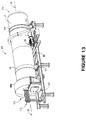
Figure 13 is an alternate perspective view of the preferred spray cooler ofFigure 12 . -
Figure 14 is a partial sectional view of the preferred spray cooler ofFigures 12 and13 . -
Figure 15 is a detailed view of a nozzle of the preferred cooling assembly of the plant illustrated inFigure 1 . - The drawings illustrate preferred embodiments of a plant for producing fuel pellets from blends of white and torrefied biomass materials. Parallel processing streams are shown therein, one for the preparation of white biomass material that is supplied from a first feed stream and the other for the preparation of torrefied biomass material that is supplied from a second feed stream. In one embodiment of the invention, the feed material for the white biomass preparation system has a higher moisture content than that for the torrefied biomass preparation system. For example, the embodiment of the invention illustrated in the drawings may be operated to prepare white wood from a first source S1 of green wood chips having a moisture content of about 30-50% by weight, while simultaneously preparing torrefied wood from a second source S2 of C&D chips having a moisture content of about 15-25% by weight. Subsequently, the white wood and the torrefied wood may be blended together for use in producing fuel pellets.
- Thus, as shown in the drawings, the preferred white biomass preparation system includes
predryer 15,biomass dryer 16 andfirst hammermill 17, and the preferred torrefied biomass preparation system includestorrefaction reactor 18,spray cooler 19 andsecond hammermill 20. Heat is supplied to both systems byheating assembly 21 which includesburner 22, heat exchanger 26 (identified as thermal oil heater inFigure 1 ) having a plurality of heat transfer coils 32 therein, andcombustion chamber 24 that is operatively connected between the burner and the heat exchanger. The heating assembly is configured and arranged so that the burner may be operated to heat a thermal fluid in the heat transfer coils to a temperature of up to about 288°C (550°F). -
Burner 22 is of a conventional type havingair inlet 28 and is adapted to burn fuel such as natural gas, propane, pulverized coal, fuel oil or the like. As best shown inFigure 2 ,burner 22 producesflame 30 incombustion chamber 24, heating air that passes intoheat exchanger 26.Heat exchanger 26 includes a plurality of heat transfer coils 32 therein, which coils are adapted to receive a thermal fluid such as thermal oil.Combustion chamber 24 is operatively connected between the burner and the heat exchanger so that air heated in the combustion chamber by the burner may be conveyed into the heat exchanger, where it will heat the thermal fluid in heat transfer coils 32.Heat exchanger 26 is equipped with a recirculation fan (not shown) that is mounted inhousing 34 and operates to draw heated air fromheat exchanger 26 throughrecirculation duct 36 and intocombustion chamber 24 for further heating.Heat exchanger 26 also includesexhaust stack 38. Preferably, the heating assembly will be operated to generate up to 21100 MJ (20 million BTUs) per hour to heat the thermal fluid within heat transfer coils 32 to a temperature of up to about 288°C (550° F). - Thermal fluid within heat transfer coils 32 is conveyed to
biomass dryer 16 andtorrefaction reactor 18 in a fluid circuit to be described hereinafter. The heating assembly includes controls such as are known to those having ordinary skill in the art to control the rate of flow of thermal fluid to the biomass dryer and the rate of flow of thermal fluid to the torrefaction reactor. In the preferred embodiment of the invention, these controls are operated, and the rotation and feed of
material into the biomass dryer and the torrefaction reactor are controlled, to insure that the thermal fluid in the biomass dryer will heat green biomass material therein (or pre-dried biomass material, as described hereinafter) to a temperature within the range of 200°F. to 240°F., while the thermal fluid in the torrefaction reactor will heat green biomass material therein to a temperature within the range of 475°F. to 550°F. The preferred heating assembly is the Convectec™ heater that is manufactured and sold by Heatec, Inc. of Chattanooga, Tennessee. -
Biomass dryer 16 includes dryer frame 42 (shown inFigures 3-5 ) havingupper end 44 andlower end 46. Generallycylindrical dryer drum 48 is mounted ondryer frame 42 for rotation about axis 50 (best shown inFigure 4 ).Dryer drum 48 includes a pair ofouter rings 52 that engagetrunnions 54 ondryer frame 42. A motor (not shown) is adapted to rotatably drive a sprocket (not shown, but located in housing 58) that is in driving engagement withdrive chain 60 which engagessprocket 62 mounted on the outer surface of the drum to rotatedryer drum 48 in a conventional manner. Alternative drive systems such as are known to those having ordinary skill in the art to which the invention relates may also be employed to rotatedryer drum 48 with respect todryer frame 42. - Because
dryer drum 48 is mounted onframe 42 havingupper end 44 andlower end 46, theaxis 50 of the drum is oriented downwardly fromupper end 64 ofdryer drum 48 tolower end 66 of the drum (best shown inFigure 5 ).Upper end 64 ofdryer drum 48 is provided withinlet 68 for green wood, andlower end 66 is provided with a discharge outlet in the form of chute 70 (best shown inFigures 5 and6 ).Dryer drum 48 is also provided with a plurality ofthermal fluid tubes 72 that extend along the interior of the drum and are adapted to circulate thermal fluid that has been heated by the heating assembly. Thus, heated fluid passes out ofthermal fluid outlet 73 ofheat exchanger 26 ofheating assembly 21 to and throughthermal fluid tubes 72 ofdryer drum 48 and back into the heat exchanger through thermal fluid inlet 74 (seeFigure 2 ). Sinceaxis 50 ofdryer drum 48 is tilted with respect to the ground on whichframe 42 is placed, rotation of the dryer drum will cause green wood introduced intoinlet 68 atupper end 64 to tumble and move downwardly towardsdischarge outlet 70 atlower end 66. As it does so, the green wood will come into contact withthermal fluid tubes 72 multiple times. Because there may be expansion of the thermal fluid as it is heated, an expansion tank 75 (seeFigures 1 and3 ) and an associated pump is provided to withdraw hot thermal fluid from the expansion tank and return it to the thermal fluid circuit as needed. - As shown in
Figures 6 and7 , the thermal fluid tubes ofdryer drum 48 are mounted through and supported by a plurality oftube support plates 150 that are spaced along the length of the dryer drum. These support plates include a plurality of tube support holes 152 that support thermal fluid tubes near the periphery of the dryer drum.Support plates 150 also support a plurality of flights or scoops 156 in the central portion of the dryer drum. Thesescoops 156 capture biomass material that has spilled out of the tube bundle into the central portion of the drum, and they direct such material back into contact with the thermal fluid tubes. The thermal fluid tubes are in fluid communication with athermal fluid manifold 158 that is supported in manifold support holes 160 insupport plates 150, so that thermal fluid can be circulated through the various fluid tubes of the drying assembly. - In converting green (or pre-dried) biomass material to white biomass material in the biomass dryer, it is preferred that the heated thermal fluid be pumped into and through
thermal fluid tubes 72 while the dryer drum is rotated at a rate sufficient to convey the green wood introduced into the inlet thereof to the discharge outlet of the dryer drum as it is heated to a temperature of at least about 93°C (200°F). Preferably, the dryer drum is of sufficient size and capacity, and is adapted to be rotated at a rate that will provide 40-50 minutes of residence time for biomass material therein. - In a preferred embodiment of the invention, the heating assembly includes a recirculation system for recirculating hot, low-oxygen gases from
exhaust stack 38 of the heat exchanger to the dryer drum in order to lower the humidity within the dryer drum. As shown inFigure 8 , this recirculation system includesoutlet line 77 from the heat exchanger, recirculatingfan 78 andinlet line 79 todryer drum 48. As the drying process is carried out inbiomass dryer 16, steam will be produced as the moisture content of the green wood is reduced. This steam will displace air in the drying drum until the oxygen content in the atmosphere of the drum is reduced to below about 9%, and more preferably below about 6%.Steam duct 80 is provided for conveying steam fromupper end 64 ofdryer drum 48 tocombustion chamber 24 ofheating assembly 21. - In the preferred embodiment of the invention illustrated in the drawings,
predryer 15 is provided to utilize heat from the flue gases passing throughexhaust stack 38 ofheat exchanger 26 to preheat green biomass material prior to its introduction intobiomass dryer 16. Once the plant is placed into operation, green biomass materials can be introduced into the predryer. As shown inFigure 9 ,predryer 15 comprises an inclined rotatingpredryer drum 162. The predryer drum is
mounted onframe 164 and includesupper end 166 andlower end 168. A rotation system for rotating the predryer drum about itslong axis 170 includes a pair ofouter rings 172 that engagetrunnions 174 onframe 164.Motor 176 is adapted to rotatably drive a sprocket (not shown, but similar to that of dryer drum 48) that is in driving engagement with a drive chain (also not shown) which engagessprocket 178 mounted on the outer surface of the drum to rotatepredryer drum 162 in a conventional manner.Hopper 180 is located atupper end 166 ofpredryer drum 162 and is in communication withinlet chute 182. The hopper is adapted to receive green biomass materials from conveyor 183 (shown inFigure 1 ). This green biomass material is pre-dried in the predryer to remove a portion of the moisture contained therein and to raise the temperature of the biomass material. - An auger or screw
conveyor 184 is preferably located ininlet chute 182 to convey green biomass material from the hopper intopredryer drum 162.Inlet line 186 for exhaust gases fromheat exchanger 26 is also located on theupper end 166 ofpredryer drum 162. During operation of this embodiment of the invention, hot flue gases from the heat exchanger are directed fromexhaust stack 38 through pipe 163 (shown in phantom inFigure 6 ) andinlet line 186 into the predryer drum so as to flow therethrough parallel to the flow of biomass. Pre-dried biomass is discharged from thelower end 168 of the predryer drum throughoutlet chute 188 ontoconveyor 190 that transports the pre-dried biomass todryer drum 48 ofbiomass dryer 16. In this embodiment of the invention, the pre-dried biomass from the outlet chute of the predryer drum is conveyed toinlet 68 ofdryer drum 48. - The dryer drum may be rotated at a rate sufficient to convey the pre-dried biomass introduced into the inlet of the dryer drum to the discharge outlet of the dryer drum as it is heated to a temperature sufficient to convert the pre-dried biomass into white wood having a heating value of up to about 20701 KJ/kg (8900BTU/lb). In the alternative, the white wood preparation system may be operated to heat biomass materials in the biomass dryer to a temperature within the range of about 182°C (350°F) to about 232°C (450°F) to produce lightly torrefied biomass having a heating value within the range of about 20701 KJ/kg (8900 BTU/lb) to about 22097 KJ/kg (9500 BTU/lb). This light torrefaction process results in the generation of a small amount of volatile organic compounds (VOCs) in the dryer drum; however, the predryer captures excess heat from the hot flue gasses produced in
heat exchanger 26 and transfers a portion of this excess heat to the green biomass material in the predrying process, thereby increasing the thermal efficiency of the white wood system. - As mentioned above, the preferred torrefied wood system includes
torrefaction reactor 18,spray cooler 19 andsecond hammermill 20. A second predryer (not shown) may also be provided upstream of the torrefaction reactor.Torrefaction reactor 18 is essentially the same asbiomass dryer 16, although the torrefied wood system is operated to heat the green biomass material in the torrefaction reactor to a temperature of at least about 246°C (475 °F) to convert it to torrefied biomass.Torrefaction reactor 18 includes reactor frame 130 (shown inFigures 10 and11 ) havingupper end 131 andlower end 132. Generallycylindrical reactor drum 133 is mounted onreactor frame 130 for rotation about axis 134 (best shown inFigure 10 ).Reactor drum 133 includes a pair ofouter rings 135 that engagetrunnions 136 onreactor frame 130. Amotor 138 is adapted to rotatably drive a sprocket (not shown, but located in housing 140) that is in driving engagement withdrive chain 142 which engagessprocket 144 mounted on the outer surface of
the drum to rotatedrum 133 in a conventional manner. Alternative drive systems such as are known to those having ordinary skill in the art to which the invention relates may also be employed to rotatedrum 133 with respect toreactor frame 130. - Because
reactor drum 133 is mounted onframe 130 havingupper end 131 andlower end 132, theaxis 134 of the drum is oriented downwardly fromupper end 131 tolower end 132.Upper end 131 ofreactor drum 133 is provided withinlet 145 for green wood, andlower end 132 is provided with a discharge outlet in the form of chute 146 (similar tochute 70 of drum 48).Inlet 145 is adapted to receive green biomass material from conveyor 147 (shown inFigure 1 ).Reactor drum 133 is also provided with a plurality of thermal fluid tubes (not shown, but similar totubes 72 of drum 48) that extend along the interior of the reactor drum and are adapted to circulate thermal fluid that has been heated by the heating assembly fromthermal fluid outlet 73 ofheat exchanger 26 ofheating assembly 21 to and through the reactor drum and back into the heat exchanger through thermal fluid inlet 74 (seeFigure 2 ). Sinceaxis 134 ofreactor drum 133 is tilted with respect to the ground on whichframe 130 is placed, rotation of the reactor drum will cause green wood introduced intoinlet 145 atupper end 131 to tumble and move downwardly towardsdischarge outlet 146 atlower end 132. As it does so, the green wood will come into contact with the thermal fluid tubes in the drum multiple times. Because there may be expansion of the thermal fluid as it is heated, expansion tank 75 (seeFigures 1 and3 ) and an associated pump is provided to withdraw hot thermal fluid from the expansion tank and return it to the thermal fluid circuit as needed. - Because the same heating assembly is used to provide heated thermal fluid to both
dryer drum 48 andreactor drum 133, a system of pumps and valves (not shown) such as are known to those having ordinary skill in the art to which the invention relates may be employed to control the rates of delivery of thermal fluid todryer drum 48 andreactor drum 133. Such a system, along with control of the feed rate of materials into each drum and the rate of rotation thereof, allows the dryer drum to heat materials therein to a temperature lower than that to which materials in the reactor drum are heated. - As the torrefaction process is carried out, steam will be produced as the moisture content of the green biomass material is reduced. This steam will displace air in the reactor drum until the oxygen content in the atmosphere of the drum is reduced to below about 9%, and more preferably below about 6%. In the torrefaction process, this steam will be contaminated with volatile organic compounds. Consequently,
steam duct 148 is provided for conveying steam fromupper end 131 ofreactor drum 133 tocombustion chamber 24 ofheating assembly 21. Any volatile organic compounds in the steam that is conveyed into the combustion chamber will be incinerated in the combustion chamber, thereby adding to the energy available for heating. In addition, the torrefaction process will strip volatile organic compounds from the off gases of drying inreactor drum 133. Because those volatile organic compounds are heavier than the steam, they will move tolower end 132 ofreactor drum 133, whereVOC duct 82 is mounted to convey these volatile organic compounds tocombustion chamber 24. Like the volatile organic compounds in the steam that is conveyed to the combustion chamber bysteam duct 148, the volatile organic compounds inVOC duct 82 will be incinerated in the combustion chamber, and will not pass throughexhaust stack 38 ofheat exchanger 26. - In one embodiment of the invention, a fuel control mechanism that is a part of the heating assembly may be operated, from control center 84 to control the supply of external fuel to
burner 22 at a first rate when the assembly is first placed into operation. Then, as volatile organic compounds are stripped from the biomass inreactor drum 133 and are conveyed tocombustion chamber 24, the rate of supply of external fuel to the burner may be reduced to a second rate that is lower than the first rate. It is contemplated that, depending on the type of biomass materials introduced into the reactor drum and the temperature of operation and rate of rotation of the reactor drum, the supply of external fuel to the burner may be shut off and continued heat supplied to the combustion chamber by the incineration of volatile organic compounds therein. - In the embodiment of the invention illustrated in the drawings, the torrefied wood preparation system also includes
spray cooler 19 that is preferably located immediately downstream oftorrefaction reactor 18, as shown inFigures 1 ,10 and11 . Spray cooler 19 includescooler frame 88 and generallycylindrical cooling drum 90. The cooling drum is mounted on the cooler frame for rotation about axis 92 (shown inFigure 13 ).Preferred cooling drum 90 includes a pair of bearing rings 94 that engagetrunnions 96 oncooler frame 88. Motor 98 (shown inFigures 12 and13 ) is adapted to rotatably drivesprocket 100 that is in driving engagement withdrive chain 102 which engages sprocket 104 mounted on the outer surface of the drum to rotate coolingdrum 90. Alternative drive systems such as are known to those having ordinary skill in the art to which the invention relates may also be employed to rotate coolingdrum 90 with respect tocooler frame 88. - Cooling
drum 90 hasinlet end 106 with an inlet opening (best shown inFigure 12 ) for introduction of torrefied wood discharged fromreactor drum 133 throughchute 146. The cooling drum also hasoutlet end 108 with adischarge outlet 110. Preferably, a plurality ofcooling tubes 112 extend along the interior of the cooling drum from the outlet end towards the inlet end, as shown inFigure 14 . In the embodiment of the cooling assembly shown in the drawings, sixcooling tubes 112 are provided, although any convenient number of cooling tubes could be employed. Preferably, as shown inFigure 14 , each coolingtube 112 has a length that is different from that of each of the other cooling tubes. Thus, coolingtube 112a is longer than all of the other cooling tubes, cooling tube 112b is longer than coolingtubes tube 112c is longer than coolingtubes 112d, 112e and 112f, cooling tube 112d is longer than coolingtubes 112e and 112f, and cooling tube 112e is longer than coolingtube 112f. Preferably, the end of coolingtube 112a is located approximately 10% of the length of the cooling drum from the inlet end, and the end of cooling tube 112b is located approximately 10% of the length of the cooling drum from the end of coolingtube 112a. Similarly, the end of coolingtube 112c is located approximately 10% of the length of the cooling drum from the end of cooling tube 112b, and the end of cooling tube 112d is located approximately 10% of the length of the cooling drum from the end of coolingtube 112c. In the same manner, the end of cooling tube 112e is located approximately 10% of the length of the cooling drum from the end of cooling tube 112d, and the end of coolingtube 112f is located approximately 10% of the length of the cooling drum from the end of cooling tube 112e. In the preferred embodiment of the invention illustrated in the drawings, each of the five cooling tubes other than the longest one is shorter by approximately 10% of the length of the cooling drum than the next longest cooling tube. - As shown in
Figure 15 , each cooling tube has anozzle 114 that is mounted on the end of the cooling tube within the cooling drum. Preferably, each nozzle has anozzle opening 116 that is configured and arranged to discharge cooling fluid downwardly from the cooling tube, most preferably at an angle of about 90° to the plane of the dynamic angle of repose of the torrefied biomass material in coolingdrum 90. Because the preferred arrangement of cooling tubes and nozzles within coolingdrum 90 spaces the nozzles along the length of the cooling drum, cooling fluid may be dispensed through the nozzles onto biomass material located throughout the drum. A pump 118, shown schematically inFigure 12 , provides the means for conveying cooling fluid, such as water, through each of the cooling tubes to be discharged through the nozzles. A plurality offlights 120 are mounted on the interior of the cooling drum and arranged to direct material frominlet end 106 to outlet end 108 as the cooling drum is rotated. Preferably, cooling water is discharged from the nozzles of the cooling tubes onto the torrefied wood in the cooling drum in quantities sufficient to reduce the temperature of the torrefied wood without adding additional moisture to the torrefied wood. Furthermore, it is preferred that the cooling fluid be discharged on the torrefied wood in the cooling drum whiledrum 90 is rotated at a rate so as to reduce the temperature of the torrefied wood at the discharge outlet to a temperature that is less than about 66°C (150°F) and more preferably to a temperature that is less than about 54°C (130°F). - In other embodiments of the invention,
spray cooler 19 may be omitted and replaced by an air-cooling system such as is known to those having ordinary skill in the art to which the invention relates. - In operating the parallel processing assemblies to process green biomass material for pelletizing into a fuel pellet, hammermill 17 is located downstream of the biomass dryer and hammermill 20 is located downstream of
spray cooler 19. These hammermills are operated to further reduce the particle size of the white wood and torrefied wood produced before a blend of such materials is delivered to one or more pellet presses 122, which are operated to compress the blend of materials to produce fuel pellets. Preferably, the white wood and the torrefied wood are blended in blendingconditioners - In the embodiment of the invention illustrated in the drawings, vented gases (including VOCs) and dust from the pellet presses are collected and conveyed back to
combustion chamber 24 where they are incinerated. Insulated or heated ducts, such asduct 126, are provided to convey gases and dust from the pellet presses tocombustion chamber 24. Pellets produced in the pellet presses are transported byconveyor 127 to rotary cooler 128 for cooling and then to screen 129. Dust and gases may also be collected downstream from the pellet presses, such as at the entry of
conveyor 127 into rotary cooler 128, where another insulated or heated duct, such asduct 192, may be employed to carry gases and dust back tocombustion chamber 24 for incineration. Other similar ducts may be provided at other points in the system where gases (especially VOCs) and dust may be collected for conveyance to the combustion chamber. - An aspect of the present invention comprises a method for making a fuel pellet from biomass materials from two separate feed sources, said method comprising:
- (A) providing a drying assembly for converting green biomass material from a first source to white biomass material, said drying assembly comprising:
- (1) a predryer that is adapted to:
- (a) receive green biomass material from the first source; and
- (b) remove moisture from and raise the temperature of the green biomass material to produce a pre-dried biomass material;
- (2) a biomass dryer that is adapted to:
- (a) receive the pre-dried dried biomass material from the predryer;
- (b) convert the pre-dried biomass material to white biomass material;
- (1) a predryer that is adapted to:
- (B) providing a torrefaction assembly for converting green biomass material from a second source to torrefied biomass material;
- (C) providing a heating assembly comprising:
- (1) a heat exchanger having a plurality of heat transfer coils therein containing a thermal fluid;
- (2) a burner for heating the thermal fluid in the heat transfer coils to a temperature within the range of about 93°C (200°F) to about 288°C (550° F), said burner also producing flue gases;
- (3) an exhaust stack for the flue gases;
- (4) means for conveying flue gases from the exhaust stack to the predryer;
- (5) means for conveying heated thermal fluid from the heat exchanger to the drying assembly;
- (6) means for conveying heated thermal fluid from the heat exchanger to the torrefaction assembly;
- (D) providing a steam duct for conveying steam from the biomass dryer to the combustion chamber;
- (E) providing a VOC duct for conveying volatile organic compounds from the biomass dryer to the combustion chamber;
- (F) providing a pellet press for compressing a blend of white biomass and torrefied biomass;
- (G) operating the burner to heat thermal fluid in the heat exchanger;
- (H) conveying heated thermal fluid to the biomass dryer;
- (I) conveying heated thermal fluid to the torrefaction assembly;
- (J) introducing green biomass from the first source into the predryer;
- (K) operating the predryer to remove moisture from and raise the temperature of the green biomass material from the first source to produce a pre-dried biomass material;
- (L) conveying the pre-dried biomass material to the biomass dryer;
- (M) operating the biomass dryer to convert the pre-dried biomass material to white biomass material;
- (N) introducing green biomass from the second source into the torrefaction assembly;
- (O) operating the torrefaction assembly to convert green biomass material from the second source to torrefied biomass material;
- (P) blending the white biomass material and the torrefied biomass material to produce a blend of biomass materials;
- (Q) conveying the blend of biomass materials to the pellet press;
- (R) operating the pellet press to compress the blend of biomass materials to produce a fuel pellet.
- The method may include operating the pellet press to compress the blend of biomass materials at a pressure of about 68948kPa (10,000 psi) in a die heated to a temperature within the range of about 260°C (550° F) to about 277°C (530° F) for a period of at least about one second.
- The method may include:(A) providing an external fuel supply to the burner;(B) providing means for controlling the supply of external fuel to the burner;(C) supplying external fuel to the burner at a first rate;(D) adjusting the rate of supply of external fuel to the burner to a second rate that is lower than the first rate, as volatile organic compounds obtained from heating the green biomass material in the biomass dryer are conveyed from the biomass dryer through the VOC duct to the combustion chamber.
Claims (15)
- An assembly for processing green biomass materials from two separate feed sources for use as a fuel pellet, said assembly comprising:(A) a drying assembly (15,16) for converting green biomass material from a first source to white biomass material, the white biomass material being green biomass material that has been dried to increase its heating value per unit of weight;(B) a torrefaction assembly (18) for converting green biomass material from a second source to torrefied biomass material;(C) a heating assembly (21) comprising:(1) a heat exchanger (26) having a plurality of heat transfer coils (32) therein containing a thermal fluid;(2) a burner (22) for heating the thermal fluid in the heat transfer coils (32) to a temperature within the range of about 93° C (200°F) to about 288°C (550°F), said burner (22) also producing flue gases;(3) means for conveying heated thermal fluid from the heat exchanger (26) to the drying assembly (16);(4) means for conveying heated thermal fluid from the heat exchanger (26) to the torrefaction assembly (18); and(D) a pellet press (122) for pelletizing a blend of biomass materials processed in the drying assembly (15,16) and biomass materials processed in the torrefaction assembly (18).
- The assembly of claim 1 which includes:a VOC duct (126) for conveying gases collected at ordownstream from the pellet press (122) to a combustion chamber (24) of the heating assembly (21).
- The assembly of claim 1 or 2:(A) which includes a predryer (15) that is adapted to receive green biomass material from a feed source and remove moisture from and raise the temperature of the green biomass material to produce a pre-dried biomass material;(B) wherein the heating assembly (21) includes an exhaust stack (38) for the flue gases;(C) which includes means for conveying flue gases from the exhaust stack (38) to the predryer (15).
- The assembly of claim 3 wherein the predryer (15) comprises:(A) an inclined rotating predryer drum (162), said drum having:(1) an upper end (166);(2) a lower end (168);(3) a long axis (170);(3) a rotation system (172,174) for rotating the drum (162) about its long axis (170);(B) an inlet chute (182) for green biomass material located at the upper end (166) of the predryer drum (162);(C) an inlet line (186) for exhaust gases from the heat exchanger (26) located at the upper end (166) of the predryer drum (162), so that hot flue gases from the heat exchanger (26) are directed into the predryer drum (162) so as to flow therethrough parallel to the flow of biomass;(D) an outlet (188) for pre-dried biomass located at the lower end of the predryer drum (162).
- The assembly of claim 1 wherein the drying assembly (15,16) comprises:(A) a predryer (15) that is adapted to:(1) receive green biomass material from the first source; and(2) remove moisture from and raise the temperature of the green biomass material to produce a pre-dried biomass material;(B) a biomass dryer (16) that is adapted to:(1) receive the pre-dried dried biomass material from the predryer (15);(2) convert the pre-dried biomass material to white biomass material.
- The assembly of claim 5 which includes a steam duct (80) for conveying steam from the biomass dryer (16) to the combustion chamber (24).
- The assembly of claim 5 which includes a VOC duct (82) for conveying volatile organic compounds from the biomass dryer (16) to the combustion chamber (24).
- The assembly of claim 5, 6 or 7, wherein the biomass dryer (16) comprises:(A) a dryer frame (42) having:(1) an upper end (44);(2) a lower end (46);(B) a generally cylindrical dryer drum (48) that is mounted on the dryer frame (42) for rotation about the axis (50) of the dryer drum (48), said dryer drum (48) having:(1) an upper end (64) having an inlet (68);(2) a lower end (66) having a discharge outlet (70);(3) a plurality of thermal fluid tubes (72) extending along the interior thereof;(C) means (52,54) for rotating the dryer drum (48) with respect to the dryer frame (42);(D) means for conveying the thermal fluid from the heat exchanger (26) of the heating assembly (21) through the thermal fluid tubes (72) in the dryer drum (48).
- The assembly of claim 8 wherein the dryer drum (48) includes:(A) a thermal fluid manifold (158) that supplies thermal fluid to the plurality of thermal fluid tubes (72);(B) a plurality of tube support plates (150) that are spaced along the length of the interior of the dryer drum (48), each of said tube support plates (150):(1) including a plurality of tube support holes (152) for supporting the plurality of thermal fluid tubes (72) near the periphery of the dryer drum (48);(2) being adapted to support a plurality of scoops (156) in the central portion of the dryer drum (48) for directing biomass material within the dryer drum (48) into contact with the plurality of thermal fluid tubes (72).
- The assembly of claim 8 or 9, which includes a recirculation system to recirculate gases from the exhaust (38) of the heat exchanger (26) to the dryer drum (48), said recirculation system comprising:(A) an outlet line (77) from the heat exchanger (26);(B) an inlet line (79) to the dryer drum (48); and(C) a recirculating fan (78) that is in fluid communication with the outlet line (77) from the heat exchanger (26) and the inlet line (79) to the dryer drum (48).
- The assembly of claim 1 wherein the torrefaction assembly includes a torrefaction reactor (18) comprising:(A) a reactor frame (130) having:(1) an upper end (131);(2) a lower end (132);(B) a generally cylindrical reactor drum (133) that is mounted on the reactor frame (130) for rotation about the axis (134) of the reactor drum (133), said reactor drum (133) having:(1) an upper end having an inlet (145);(2) a lower end having a discharge outlet (146);(3) a plurality of thermal fluid tubes extending along the interior thereof;(C) means (135,136) for rotating the reactor drum (133) with respect to the reactor frame (130);(D) means for conveying the thermal fluid from the heat exchanger (26) of the heating assembly (21) through the thermal fluid tubes in the reactor drum (133).
- The assembly of claim 11 wherein the reactor drum (133) includes:(A) a thermal fluid manifold that supplies thermal fluid to the plurality of thermal fluid tubes;(B) a plurality of tube support plates that are spaced along the length of the interior of the reactor drum (133), each of said tube support plates:(1) including a plurality of tube support holes for supporting the plurality of thermal fluid tubes near the periphery of the reactor drum (133);(2) being adapted to support a plurality of scoops in the central portion of the reactor drum (133) for directing biomass material within the reactor drum (133) into contact with the plurality of thermal fluid tubes.
- The assembly of claim 11 or 12, wherein the torrefaction assembly includes:(A) a cooling assembly (19) located downstream of the torrefaction reactor (18);(B) means for conveying torrefied biomass material from the discharge outlet (146) of the reactor drum (133) to the cooling assembly (19).
- The assembly of claim 13 wherein the cooling assembly (19) comprises:(A) a cooler frame (88);(B) a generally cylindrical cooling drum (90) that is mounted on the cooler frame (88) for rotation about the axis (92) of the cooling drum (90), said cooling drum (90) having:(1) an inlet end (160) with an inlet;(2) an outlet end (108) with a discharge outlet (110);(3) a cooling tube (112) extending along the interior thereof;(4) a nozzle (114) mounted on the end of the cooling tube (112) within the cooling drum (90), which nozzle (114) has a nozzle opening (116) that is configured and arranged to discharge cooling fluid downwardly from the cooling tube (112);(5) a plurality of flights (120) mounted on the interior of the cooling drum (90) and arranged to direct material from the inlet end (106) to the outlet end (108) as the cooling drum (90) is rotated;(C) means (94,96) for rotating the cooling drum (90) with respect to the cooler frame (88);(D) means (118) for conveying cooling fluid through the cooling tube (112) to be discharged through the nozzle (114).
- The assembly of claim 14 wherein the cooling assembly (19) comprises:(A) a plurality of cooling tubes (112a-112f) extending along the interior of the cooling drum (90), each of which has a length that is different from that of each of the other cooling tubes;(B) a plurality of nozzles (114), with at least one nozzle being mounted on the end of each of the cooling tubes (112a-112f) within the cooling drum (90);(C) means (118) for conveying cooling fluid through each of the cooling tubes (112a-112f) to be discharged through the nozzles (114);wherein each of the nozzles (114) is oriented so as to direct the cooling fluid downwardly at an angle of approximately 90° to the plane of the dynamic angle of repose of the biomass material in the cooling drum (90); and
the end of the longest cooling tube is spaced approximately 10% of the length of the cooling drum (90) from the inlet thereof, and each of the cooling tubes other than the longest one is shorter by approximately 10% of the length of the cooling drum (90) than the next longest cooling tube.
Priority Applications (1)
| Application Number | Priority Date | Filing Date | Title |
|---|---|---|---|
| PL13848257T PL2912150T3 (en) | 2012-10-25 | 2013-10-24 | Method and apparatus for pelletizing blends of biomass materials for use as fuel |
Applications Claiming Priority (2)
| Application Number | Priority Date | Filing Date | Title |
|---|---|---|---|
| US201261718282P | 2012-10-25 | 2012-10-25 | |
| PCT/US2013/066503 WO2014066575A1 (en) | 2012-10-25 | 2013-10-24 | Method and apparatus for pelletizing blends of biomass materials for use as fuel |
Publications (3)
| Publication Number | Publication Date |
|---|---|
| EP2912150A1 EP2912150A1 (en) | 2015-09-02 |
| EP2912150A4 EP2912150A4 (en) | 2016-06-01 |
| EP2912150B1 true EP2912150B1 (en) | 2017-09-06 |
Family
ID=50545238
Family Applications (1)
| Application Number | Title | Priority Date | Filing Date |
|---|---|---|---|
| EP13848257.5A Not-in-force EP2912150B1 (en) | 2012-10-25 | 2013-10-24 | Method and apparatus for pelletizing blends of biomass materials for use as fuel |
Country Status (5)
| Country | Link |
|---|---|
| EP (1) | EP2912150B1 (en) |
| DK (1) | DK2912150T3 (en) |
| ES (1) | ES2643587T3 (en) |
| PL (1) | PL2912150T3 (en) |
| WO (1) | WO2014066575A1 (en) |
Families Citing this family (3)
| Publication number | Priority date | Publication date | Assignee | Title |
|---|---|---|---|---|
| US10221359B2 (en) * | 2016-09-20 | 2019-03-05 | Anthony Phan | Biomass treatment process and apparatus |
| GR1010526B (en) * | 2022-10-12 | 2023-08-10 | Δενεσακης, Ιωαννης Αναστασιου | Method and system (mechanism) integrated into the production process of the technology used in the conversion of solid biomass into, inter alia, solid biofuel pellets and briquettes |
| EP4660285A1 (en) * | 2024-06-07 | 2025-12-10 | Perpetual Next Technologies B.V. | Cooling system for hot biocoal |
Family Cites Families (25)
| Publication number | Priority date | Publication date | Assignee | Title |
|---|---|---|---|---|
| NL7309900A (en) * | 1973-07-16 | 1975-01-20 | Expert Nv | COOLER DRYER OF CASTINGS AND MOLDING SAND. |
| US3822651A (en) * | 1973-09-04 | 1974-07-09 | D Harris | Water cooled kiln for waste disposal |
| US4401436A (en) * | 1981-12-21 | 1983-08-30 | Atlantic Richfield Company | Process for cooling particulate coal |
| US4482253A (en) * | 1983-03-28 | 1984-11-13 | Joy Manufacturing Company | Rotary material processor |
| US5217578A (en) * | 1989-05-22 | 1993-06-08 | Alberta Oil Sands Technology And Research Authority | Dry thermal processor |
| US7090013B2 (en) * | 2001-10-24 | 2006-08-15 | Shell Oil Company | In situ thermal processing of a hydrocarbon containing formation to produce heated fluids |
| US20030221363A1 (en) * | 2002-05-21 | 2003-12-04 | Reed Thomas B. | Process and apparatus for making a densified torrefied fuel |
| US8523963B2 (en) * | 2004-10-12 | 2013-09-03 | Great River Energy | Apparatus for heat treatment of particulate materials |
| US8062410B2 (en) * | 2004-10-12 | 2011-11-22 | Great River Energy | Apparatus and method of enhancing the quality of high-moisture materials and separating and concentrating organic and/or non-organic material contained therein |
| NL1030864C2 (en) * | 2006-01-06 | 2007-07-09 | Stichting Energie | Method and device for treating biomass. |
| US7942942B2 (en) * | 2006-05-21 | 2011-05-17 | Paoluccio John A | Method and apparatus for biomass torrefaction, manufacturing a storable fuel from biomass and producing offsets for the combustion products of fossil fuels and a combustible article of manufacture |
| US20100124583A1 (en) * | 2008-04-30 | 2010-05-20 | Xyleco, Inc. | Processing biomass |
| US20090056206A1 (en) * | 2007-08-28 | 2009-03-05 | Stephane Gauthier | Method for manufacture of plant biomass solid fuel |
| US8669404B2 (en) * | 2008-10-15 | 2014-03-11 | Renewable Fuel Technologies, Inc. | Method for conversion of biomass to biofuel |
| AU2010210195A1 (en) * | 2009-02-04 | 2011-07-28 | Shell Internationale Research Maatschappij B.V. | Process to convert biomass |
| US8276289B2 (en) * | 2009-03-27 | 2012-10-02 | Terra Green Energy, Llc | System and method for preparation of solid biomass by torrefaction |
| CN102741383A (en) * | 2009-05-26 | 2012-10-17 | 美国颗粒供电有限责任公司 | Pellets and briquettes from compacted biomass |
| CA2760840C (en) * | 2009-08-24 | 2014-12-02 | Board Of Trustees Of Michigan State University | Pretreated densified biomass products and methods of making and using same |
| US20110179700A1 (en) * | 2010-03-22 | 2011-07-28 | James Russell Monroe | System and Method for Torrefaction and Processing of Biomass |
| US8246788B2 (en) * | 2010-10-08 | 2012-08-21 | Teal Sales Incorporated | Biomass torrefaction system and method |
| US8877015B2 (en) * | 2010-11-04 | 2014-11-04 | Kior, Inc. | Process control by blending biomass feedstocks |
| US10377954B2 (en) * | 2010-11-09 | 2019-08-13 | Board Of Regents Of The Nevada System Of Higher Education, On Behalf Of The University Of Nevada, Reno | Method for wet torrefaction of a biomass |
| DE102011005065A1 (en) * | 2011-03-03 | 2012-09-06 | Siemens Aktiengesellschaft | Thermal treatment of biomass, comprises e.g. indirect drying of biomass, obtaining heating steam by compressing dried steam vapor escaping from biomass, supplying heating steam in heating tube of drying apparatus and condensing |
| DE102011016003A1 (en) * | 2011-04-04 | 2012-10-04 | Tom Sieverts | Plant useful for torrefaction of biomass, preferably wood chips, wood- and plant remains comprises feeding device, torrefaction device, extraction device and supply device for operating functional units |
| US8100990B2 (en) * | 2011-05-15 | 2012-01-24 | Avello Bioenery, Inc. | Methods for integrated fast pyrolysis processing of biomass |
-
2013
- 2013-10-24 ES ES13848257.5T patent/ES2643587T3/en active Active
- 2013-10-24 WO PCT/US2013/066503 patent/WO2014066575A1/en not_active Ceased
- 2013-10-24 DK DK13848257.5T patent/DK2912150T3/en active
- 2013-10-24 EP EP13848257.5A patent/EP2912150B1/en not_active Not-in-force
- 2013-10-24 PL PL13848257T patent/PL2912150T3/en unknown
Non-Patent Citations (1)
| Title |
|---|
| None * |
Also Published As
| Publication number | Publication date |
|---|---|
| ES2643587T3 (en) | 2017-11-23 |
| EP2912150A1 (en) | 2015-09-02 |
| DK2912150T3 (en) | 2017-11-06 |
| WO2014066575A1 (en) | 2014-05-01 |
| EP2912150A4 (en) | 2016-06-01 |
| PL2912150T3 (en) | 2018-06-29 |
Similar Documents
| Publication | Publication Date | Title |
|---|---|---|
| US9562204B2 (en) | Method and apparatus for pelletizing blends of biomass materials for use as fuel | |
| US9127227B2 (en) | Method and apparatus for processing biomass material | |
| US8156662B2 (en) | Systems for prevention of HAP emissions and for efficient drying/dehydration processes | |
| US8322056B2 (en) | System and method for preparation of solid biomass by torrefaction | |
| CN102822322B (en) | Plant and method for producing finely divided fuels from solid or pasty energy raw materials by means of roasting and pulverizing | |
| NO20110041A1 (en) | Process and apparatus for the production of dry-traced lignocellulosic material | |
| WO2012074374A1 (en) | Apparatus and process for the thermal treatment of biomass | |
| US20160304800A1 (en) | Torrefaction Process | |
| US10450523B2 (en) | Method and apparatus for torrefaction of biomass with a cyclonic bed reactor | |
| EP1770152A1 (en) | Method and device for pelletizing unprocessed sugar-cane bagasse | |
| NL2013008C2 (en) | Apparatus and process for the thermal treatment of biomass. | |
| EP2016158A1 (en) | Process for producing electrical energy from biomass | |
| WO2014066575A1 (en) | Method and apparatus for pelletizing blends of biomass materials for use as fuel | |
| JP7108354B1 (en) | Production equipment for semi-carbonized pellets for biomass fuel and biomass power generation system | |
| RU2241904C1 (en) | Complex for processing solid fuel on bioresources base and producing thermal energy | |
| EP3004738B1 (en) | Production plant of thermal energy and/or electricity from biomass | |
| EP2622294A1 (en) | Drying apparatus | |
| WO2013040305A1 (en) | Method and apparatus for processing biomass material | |
| BG1736U1 (en) | Technological line for obtaining electrical and thermal energy from biomass |
Legal Events
| Date | Code | Title | Description |
|---|---|---|---|
| PUAI | Public reference made under article 153(3) epc to a published international application that has entered the european phase |
Free format text: ORIGINAL CODE: 0009012 |
|
| 17P | Request for examination filed |
Effective date: 20150518 |
|
| AK | Designated contracting states |
Kind code of ref document: A1 Designated state(s): AL AT BE BG CH CY CZ DE DK EE ES FI FR GB GR HR HU IE IS IT LI LT LU LV MC MK MT NL NO PL PT RO RS SE SI SK SM TR |
|
| AX | Request for extension of the european patent |
Extension state: BA ME |
|
| RIN1 | Information on inventor provided before grant (corrected) |
Inventor name: BROCK, J. DONALD Inventor name: SWANSON, MALCOLM L. |
|
| DAX | Request for extension of the european patent (deleted) | ||
| RA4 | Supplementary search report drawn up and despatched (corrected) |
Effective date: 20160503 |
|
| RIC1 | Information provided on ipc code assigned before grant |
Ipc: C10L 5/44 20060101AFI20160427BHEP |
|
| GRAP | Despatch of communication of intention to grant a patent |
Free format text: ORIGINAL CODE: EPIDOSNIGR1 |
|
| INTG | Intention to grant announced |
Effective date: 20170510 |
|
| GRAS | Grant fee paid |
Free format text: ORIGINAL CODE: EPIDOSNIGR3 |
|
| GRAA | (expected) grant |
Free format text: ORIGINAL CODE: 0009210 |
|
| AK | Designated contracting states |
Kind code of ref document: B1 Designated state(s): AL AT BE BG CH CY CZ DE DK EE ES FI FR GB GR HR HU IE IS IT LI LT LU LV MC MK MT NL NO PL PT RO RS SE SI SK SM TR |
|
| REG | Reference to a national code |
Ref country code: GB Ref legal event code: FG4D |
|
| REG | Reference to a national code |
Ref country code: CH Ref legal event code: EP Ref country code: AT Ref legal event code: REF Ref document number: 925922 Country of ref document: AT Kind code of ref document: T Effective date: 20170915 |
|
| REG | Reference to a national code |
Ref country code: IE Ref legal event code: FG4D |
|
| REG | Reference to a national code |
Ref country code: DE Ref legal event code: R096 Ref document number: 602013026377 Country of ref document: DE |
|
| REG | Reference to a national code |
Ref country code: FR Ref legal event code: PLFP Year of fee payment: 5 |
|
| REG | Reference to a national code |
Ref country code: DK Ref legal event code: T3 Effective date: 20171101 |
|
| REG | Reference to a national code |
Ref country code: ES Ref legal event code: FG2A Ref document number: 2643587 Country of ref document: ES Kind code of ref document: T3 Effective date: 20171123 |
|
| REG | Reference to a national code |
Ref country code: SE Ref legal event code: TRGR |
|
| REG | Reference to a national code |
Ref country code: NL Ref legal event code: FP |
|
| REG | Reference to a national code |
Ref country code: LT Ref legal event code: MG4D |
|
| PG25 | Lapsed in a contracting state [announced via postgrant information from national office to epo] |
Ref country code: FI Free format text: LAPSE BECAUSE OF FAILURE TO SUBMIT A TRANSLATION OF THE DESCRIPTION OR TO PAY THE FEE WITHIN THE PRESCRIBED TIME-LIMIT Effective date: 20170906 Ref country code: HR Free format text: LAPSE BECAUSE OF FAILURE TO SUBMIT A TRANSLATION OF THE DESCRIPTION OR TO PAY THE FEE WITHIN THE PRESCRIBED TIME-LIMIT Effective date: 20170906 Ref country code: NO Free format text: LAPSE BECAUSE OF FAILURE TO SUBMIT A TRANSLATION OF THE DESCRIPTION OR TO PAY THE FEE WITHIN THE PRESCRIBED TIME-LIMIT Effective date: 20171206 Ref country code: LT Free format text: LAPSE BECAUSE OF FAILURE TO SUBMIT A TRANSLATION OF THE DESCRIPTION OR TO PAY THE FEE WITHIN THE PRESCRIBED TIME-LIMIT Effective date: 20170906 |
|
| PG25 | Lapsed in a contracting state [announced via postgrant information from national office to epo] |
Ref country code: GR Free format text: LAPSE BECAUSE OF FAILURE TO SUBMIT A TRANSLATION OF THE DESCRIPTION OR TO PAY THE FEE WITHIN THE PRESCRIBED TIME-LIMIT Effective date: 20171207 Ref country code: LV Free format text: LAPSE BECAUSE OF FAILURE TO SUBMIT A TRANSLATION OF THE DESCRIPTION OR TO PAY THE FEE WITHIN THE PRESCRIBED TIME-LIMIT Effective date: 20170906 Ref country code: RS Free format text: LAPSE BECAUSE OF FAILURE TO SUBMIT A TRANSLATION OF THE DESCRIPTION OR TO PAY THE FEE WITHIN THE PRESCRIBED TIME-LIMIT Effective date: 20170906 Ref country code: BG Free format text: LAPSE BECAUSE OF FAILURE TO SUBMIT A TRANSLATION OF THE DESCRIPTION OR TO PAY THE FEE WITHIN THE PRESCRIBED TIME-LIMIT Effective date: 20171206 |
|
| PG25 | Lapsed in a contracting state [announced via postgrant information from national office to epo] |
Ref country code: CZ Free format text: LAPSE BECAUSE OF FAILURE TO SUBMIT A TRANSLATION OF THE DESCRIPTION OR TO PAY THE FEE WITHIN THE PRESCRIBED TIME-LIMIT Effective date: 20170906 Ref country code: RO Free format text: LAPSE BECAUSE OF FAILURE TO SUBMIT A TRANSLATION OF THE DESCRIPTION OR TO PAY THE FEE WITHIN THE PRESCRIBED TIME-LIMIT Effective date: 20170906 |
|
| PG25 | Lapsed in a contracting state [announced via postgrant information from national office to epo] |
Ref country code: EE Free format text: LAPSE BECAUSE OF FAILURE TO SUBMIT A TRANSLATION OF THE DESCRIPTION OR TO PAY THE FEE WITHIN THE PRESCRIBED TIME-LIMIT Effective date: 20170906 Ref country code: IS Free format text: LAPSE BECAUSE OF FAILURE TO SUBMIT A TRANSLATION OF THE DESCRIPTION OR TO PAY THE FEE WITHIN THE PRESCRIBED TIME-LIMIT Effective date: 20180106 Ref country code: SM Free format text: LAPSE BECAUSE OF FAILURE TO SUBMIT A TRANSLATION OF THE DESCRIPTION OR TO PAY THE FEE WITHIN THE PRESCRIBED TIME-LIMIT Effective date: 20170906 Ref country code: SK Free format text: LAPSE BECAUSE OF FAILURE TO SUBMIT A TRANSLATION OF THE DESCRIPTION OR TO PAY THE FEE WITHIN THE PRESCRIBED TIME-LIMIT Effective date: 20170906 |
|
| REG | Reference to a national code |
Ref country code: CH Ref legal event code: PL |
|
| REG | Reference to a national code |
Ref country code: DE Ref legal event code: R097 Ref document number: 602013026377 Country of ref document: DE |
|
| PG25 | Lapsed in a contracting state [announced via postgrant information from national office to epo] |
Ref country code: MC Free format text: LAPSE BECAUSE OF FAILURE TO SUBMIT A TRANSLATION OF THE DESCRIPTION OR TO PAY THE FEE WITHIN THE PRESCRIBED TIME-LIMIT Effective date: 20170906 |
|
| PLBE | No opposition filed within time limit |
Free format text: ORIGINAL CODE: 0009261 |
|
| STAA | Information on the status of an ep patent application or granted ep patent |
Free format text: STATUS: NO OPPOSITION FILED WITHIN TIME LIMIT |
|
| PG25 | Lapsed in a contracting state [announced via postgrant information from national office to epo] |
Ref country code: LI Free format text: LAPSE BECAUSE OF NON-PAYMENT OF DUE FEES Effective date: 20171031 Ref country code: CH Free format text: LAPSE BECAUSE OF NON-PAYMENT OF DUE FEES Effective date: 20171031 Ref country code: LU Free format text: LAPSE BECAUSE OF NON-PAYMENT OF DUE FEES Effective date: 20171024 |
|
| 26N | No opposition filed |
Effective date: 20180607 |
|
| PG25 | Lapsed in a contracting state [announced via postgrant information from national office to epo] |
Ref country code: SI Free format text: LAPSE BECAUSE OF FAILURE TO SUBMIT A TRANSLATION OF THE DESCRIPTION OR TO PAY THE FEE WITHIN THE PRESCRIBED TIME-LIMIT Effective date: 20170906 |
|
| PG25 | Lapsed in a contracting state [announced via postgrant information from national office to epo] |
Ref country code: MT Free format text: LAPSE BECAUSE OF NON-PAYMENT OF DUE FEES Effective date: 20171024 |
|
| REG | Reference to a national code |
Ref country code: FR Ref legal event code: PLFP Year of fee payment: 6 |
|
| PGFP | Annual fee paid to national office [announced via postgrant information from national office to epo] |
Ref country code: NL Payment date: 20181022 Year of fee payment: 6 |
|
| PGFP | Annual fee paid to national office [announced via postgrant information from national office to epo] |
Ref country code: PL Payment date: 20181018 Year of fee payment: 6 Ref country code: IE Payment date: 20181022 Year of fee payment: 6 Ref country code: DE Payment date: 20181024 Year of fee payment: 6 Ref country code: DK Payment date: 20181025 Year of fee payment: 6 Ref country code: AT Payment date: 20181019 Year of fee payment: 6 Ref country code: SE Payment date: 20181025 Year of fee payment: 6 |
|
| PGFP | Annual fee paid to national office [announced via postgrant information from national office to epo] |
Ref country code: GB Payment date: 20181031 Year of fee payment: 6 Ref country code: IT Payment date: 20181022 Year of fee payment: 6 Ref country code: TR Payment date: 20181016 Year of fee payment: 6 Ref country code: BE Payment date: 20181022 Year of fee payment: 6 Ref country code: ES Payment date: 20181122 Year of fee payment: 6 Ref country code: FR Payment date: 20181023 Year of fee payment: 6 |
|
| PG25 | Lapsed in a contracting state [announced via postgrant information from national office to epo] |
Ref country code: HU Free format text: LAPSE BECAUSE OF FAILURE TO SUBMIT A TRANSLATION OF THE DESCRIPTION OR TO PAY THE FEE WITHIN THE PRESCRIBED TIME-LIMIT; INVALID AB INITIO Effective date: 20131024 |
|
| REG | Reference to a national code |
Ref country code: AT Ref legal event code: UEP Ref document number: 925922 Country of ref document: AT Kind code of ref document: T Effective date: 20170906 |
|
| PG25 | Lapsed in a contracting state [announced via postgrant information from national office to epo] |
Ref country code: CY Free format text: LAPSE BECAUSE OF FAILURE TO SUBMIT A TRANSLATION OF THE DESCRIPTION OR TO PAY THE FEE WITHIN THE PRESCRIBED TIME-LIMIT Effective date: 20170906 |
|
| PG25 | Lapsed in a contracting state [announced via postgrant information from national office to epo] |
Ref country code: MK Free format text: LAPSE BECAUSE OF FAILURE TO SUBMIT A TRANSLATION OF THE DESCRIPTION OR TO PAY THE FEE WITHIN THE PRESCRIBED TIME-LIMIT Effective date: 20170906 |
|
| REG | Reference to a national code |
Ref country code: DE Ref legal event code: R119 Ref document number: 602013026377 Country of ref document: DE |
|
| REG | Reference to a national code |
Ref country code: DK Ref legal event code: EBP Effective date: 20191031 |
|
| PG25 | Lapsed in a contracting state [announced via postgrant information from national office to epo] |
Ref country code: PT Free format text: LAPSE BECAUSE OF FAILURE TO SUBMIT A TRANSLATION OF THE DESCRIPTION OR TO PAY THE FEE WITHIN THE PRESCRIBED TIME-LIMIT Effective date: 20170906 |
|
| REG | Reference to a national code |
Ref country code: NL Ref legal event code: MM Effective date: 20191101 |
|
| PG25 | Lapsed in a contracting state [announced via postgrant information from national office to epo] |
Ref country code: DE Free format text: LAPSE BECAUSE OF NON-PAYMENT OF DUE FEES Effective date: 20200501 Ref country code: AL Free format text: LAPSE BECAUSE OF FAILURE TO SUBMIT A TRANSLATION OF THE DESCRIPTION OR TO PAY THE FEE WITHIN THE PRESCRIBED TIME-LIMIT Effective date: 20170906 |
|
| REG | Reference to a national code |
Ref country code: BE Ref legal event code: MM Effective date: 20191031 |
|
| REG | Reference to a national code |
Ref country code: AT Ref legal event code: MM01 Ref document number: 925922 Country of ref document: AT Kind code of ref document: T Effective date: 20191024 |
|
| PG25 | Lapsed in a contracting state [announced via postgrant information from national office to epo] |
Ref country code: BE Free format text: LAPSE BECAUSE OF NON-PAYMENT OF DUE FEES Effective date: 20191031 Ref country code: SE Free format text: LAPSE BECAUSE OF NON-PAYMENT OF DUE FEES Effective date: 20191025 Ref country code: NL Free format text: LAPSE BECAUSE OF NON-PAYMENT OF DUE FEES Effective date: 20191101 |
|
| GBPC | Gb: european patent ceased through non-payment of renewal fee |
Effective date: 20191024 |
|
| PG25 | Lapsed in a contracting state [announced via postgrant information from national office to epo] |
Ref country code: IT Free format text: LAPSE BECAUSE OF NON-PAYMENT OF DUE FEES Effective date: 20191024 Ref country code: IE Free format text: LAPSE BECAUSE OF NON-PAYMENT OF DUE FEES Effective date: 20191024 Ref country code: GB Free format text: LAPSE BECAUSE OF NON-PAYMENT OF DUE FEES Effective date: 20191024 Ref country code: FR Free format text: LAPSE BECAUSE OF NON-PAYMENT OF DUE FEES Effective date: 20191031 Ref country code: DK Free format text: LAPSE BECAUSE OF NON-PAYMENT OF DUE FEES Effective date: 20191031 |
|
| PG25 | Lapsed in a contracting state [announced via postgrant information from national office to epo] |
Ref country code: AT Free format text: LAPSE BECAUSE OF NON-PAYMENT OF DUE FEES Effective date: 20191024 |
|
| PG25 | Lapsed in a contracting state [announced via postgrant information from national office to epo] |
Ref country code: ES Free format text: LAPSE BECAUSE OF NON-PAYMENT OF DUE FEES Effective date: 20191025 |
|
| PG25 | Lapsed in a contracting state [announced via postgrant information from national office to epo] |
Ref country code: TR Free format text: LAPSE BECAUSE OF NON-PAYMENT OF DUE FEES Effective date: 20191024 |
|
| PG25 | Lapsed in a contracting state [announced via postgrant information from national office to epo] |
Ref country code: PL Free format text: LAPSE BECAUSE OF NON-PAYMENT OF DUE FEES Effective date: 20191024 |