EP2911828B1 - Basin wrench - Google Patents
Basin wrench Download PDFInfo
- Publication number
- EP2911828B1 EP2911828B1 EP13848146.0A EP13848146A EP2911828B1 EP 2911828 B1 EP2911828 B1 EP 2911828B1 EP 13848146 A EP13848146 A EP 13848146A EP 2911828 B1 EP2911828 B1 EP 2911828B1
- Authority
- EP
- European Patent Office
- Prior art keywords
- bar
- housing
- support
- hub
- handle
- Prior art date
- Legal status (The legal status is an assumption and is not a legal conclusion. Google has not performed a legal analysis and makes no representation as to the accuracy of the status listed.)
- Active
Links
Images




Classifications
-
- B—PERFORMING OPERATIONS; TRANSPORTING
- B25—HAND TOOLS; PORTABLE POWER-DRIVEN TOOLS; MANIPULATORS
- B25B—TOOLS OR BENCH DEVICES NOT OTHERWISE PROVIDED FOR, FOR FASTENING, CONNECTING, DISENGAGING, OR HOLDING
- B25B13/00—Spanners; Wrenches
- B25B13/48—Spanners; Wrenches for special purposes
- B25B13/481—Spanners; Wrenches for special purposes for operating in areas having limited access
-
- B—PERFORMING OPERATIONS; TRANSPORTING
- B25—HAND TOOLS; PORTABLE POWER-DRIVEN TOOLS; MANIPULATORS
- B25B—TOOLS OR BENCH DEVICES NOT OTHERWISE PROVIDED FOR, FOR FASTENING, CONNECTING, DISENGAGING, OR HOLDING
- B25B13/00—Spanners; Wrenches
- B25B13/10—Spanners; Wrenches with adjustable jaws
- B25B13/28—Spanners; Wrenches with adjustable jaws the jaws being pivotally movable
-
- B—PERFORMING OPERATIONS; TRANSPORTING
- B25—HAND TOOLS; PORTABLE POWER-DRIVEN TOOLS; MANIPULATORS
- B25B—TOOLS OR BENCH DEVICES NOT OTHERWISE PROVIDED FOR, FOR FASTENING, CONNECTING, DISENGAGING, OR HOLDING
- B25B13/00—Spanners; Wrenches
- B25B13/48—Spanners; Wrenches for special purposes
- B25B13/50—Spanners; Wrenches for special purposes for operating on work of special profile, e.g. pipes
- B25B13/5008—Spanners; Wrenches for special purposes for operating on work of special profile, e.g. pipes for operating on pipes or cylindrical objects
- B25B13/5016—Spanners; Wrenches for special purposes for operating on work of special profile, e.g. pipes for operating on pipes or cylindrical objects by externally gripping the pipe
- B25B13/5025—Spanners; Wrenches for special purposes for operating on work of special profile, e.g. pipes for operating on pipes or cylindrical objects by externally gripping the pipe using a pipe wrench type tool
- B25B13/5041—Spanners; Wrenches for special purposes for operating on work of special profile, e.g. pipes for operating on pipes or cylindrical objects by externally gripping the pipe using a pipe wrench type tool with movable or adjustable jaws
- B25B13/505—Pivotally moving or adjustable
-
- B—PERFORMING OPERATIONS; TRANSPORTING
- B25—HAND TOOLS; PORTABLE POWER-DRIVEN TOOLS; MANIPULATORS
- B25B—TOOLS OR BENCH DEVICES NOT OTHERWISE PROVIDED FOR, FOR FASTENING, CONNECTING, DISENGAGING, OR HOLDING
- B25B23/00—Details of, or accessories for, spanners, wrenches, screwdrivers
- B25B23/16—Handles
-
- B—PERFORMING OPERATIONS; TRANSPORTING
- B25—HAND TOOLS; PORTABLE POWER-DRIVEN TOOLS; MANIPULATORS
- B25B—TOOLS OR BENCH DEVICES NOT OTHERWISE PROVIDED FOR, FOR FASTENING, CONNECTING, DISENGAGING, OR HOLDING
- B25B23/00—Details of, or accessories for, spanners, wrenches, screwdrivers
- B25B23/18—Devices for illuminating the head of the screw or the nut
-
- B—PERFORMING OPERATIONS; TRANSPORTING
- B25—HAND TOOLS; PORTABLE POWER-DRIVEN TOOLS; MANIPULATORS
- B25G—HANDLES FOR HAND IMPLEMENTS
- B25G1/00—Handle constructions
- B25G1/005—Handle constructions for screwdrivers, wrenches or spanners with additional levers, e.g. for increasing torque
- B25G1/007—Handle constructions for screwdrivers, wrenches or spanners with additional levers, e.g. for increasing torque of crank type
-
- B—PERFORMING OPERATIONS; TRANSPORTING
- B25—HAND TOOLS; PORTABLE POWER-DRIVEN TOOLS; MANIPULATORS
- B25G—HANDLES FOR HAND IMPLEMENTS
- B25G1/00—Handle constructions
- B25G1/06—Handle constructions reversible or adjustable for position
- B25G1/063—Handle constructions reversible or adjustable for position for screwdrivers, wrenches or spanners
Definitions
- the present subject matter relates to hand tools and particularly those for use in plumbing applications. More specifically, the present subject matter relates to basin wrenches.
- Basin nuts used to secure kitchen and vanity faucets, kitchen spray hoses, toilet ballcocks and the like usually are located in confined areas that are difficult to engage with a wrench. Many plastic nuts have wings or flanges to facilitate turning of the nuts by hand. In many cases, however, it still is necessary to use a wrench with such nuts to ensure tightness and also to loosen nuts which may have become “frozen” in place either through over-tightening or as a result of dissolved salts or minerals in the water.
- the space under sinks is very limited due to an enclosed area having a plurality of supply lines, a drain assembly and other such obstacles thus making simple operations like disconnecting a supply line difficult with wrenches that are positioned to extend perpendicular to the fitting.
- a basin wrench is a plumbing tool for removing and installing sink faucets and is often used in such instances.
- a basin wrench generally has a long handle that is directed upward from under a sink to turn nuts on fittings and faucets.
- a basin wrench is normally used to loosen or tighten locknuts for supply hoses attached to compression fittings.
- basin wrenches are known in the art, most include one or more metal members as a handle and can be difficult to grasp particularly if water, oils, or other contaminants are deposited thereon.
- an auxiliary cross handle is provided such as for facilitating rotation of the wrench, the outwardly extending cross handle renders the wrench difficult to store in a tool box or other small space.
- basin wrenches Although a variety of basin and faucet wrenches are known in the art, a need remains for a basin wrench that further promotes ease and convenience of use, facilitates engagement and gripping of fittings or other components, is relatively compact when not in use, and which ergonomically combines multiple features in a single device which can be economically manufactured.
- the present subject matter provides a basin wrench comprising a telescoping support assembly according to claim 1.
- a basin wrench comprising a telescoping support assembly.
- the telescoping support assembly defines a distal end and an opposite proximal end.
- the telescoping support assembly defines a longitudinal axis.
- the wrench also comprises a lower jaw pivotally attached to the distal end of the support assembly.
- the lower jaw is pivotable about a first axis that is perpendicular to the longitudinal axis of the support assembly.
- the wrench also comprises an upper jaw pivotally attached to the lower jaw.
- the wrench also comprises a T-bar assembly pivotally and removably attached to the proximal end of the support assembly.
- the T-bar assembly includes a hub defining an aperture extending through the hub and a bar slidingly disposed in the aperture of the hub.
- the hub of the T-bar assembly is pivotable about a second axis that is perpendicular to both (i) the first axis about which the lower jaw is pivotable, and (ii) the longitudinal axis of the support assembly.
- the wrench also comprises a housing generally enclosing the support assembly. The housing defines a gripping region. The housing is formed from a polymeric material.
- the wrench also comprises a light assembly incorporated within the housing and located such that upon emission of light from the light assembly, emitted light irradiates at least a portion of the lower jaw and the upper jaw.
- the present subject matter provides a basin wrench comprising a telescoping support assembly defining a distal end, a proximal end, and a longitudinal axis.
- the basin wrench also comprises a pair of jaws pivotally attached to each other. The pair of jaws are pivotally attached to the distal end of the telescoping support assembly.
- the wrench also comprises a polymeric housing generally enclosing the support assembly. The housing defines a front face, an oppositely directed rear face, a first side extending between the front face and the rear face, and a second side extending between the front face and the rear face.
- the front face includes a contoured gripping region.
- the basin wrench also comprises a swivel handle assembly pivotally and removably attached to the proximal end of the support assembly.
- the swivel handle assembly includes a hub that is pivotally and removably attached to the proximal end of the support assembly.
- the hub defines an aperture extending through the hub.
- the swivel handle assembly includes a bar slidably disposed in the aperture defined by the hub. The swivel handle is positionable between a use position in which the bar is perpendicular to the longitudinal axis of the support assembly and a stowed position in which the bar is parallel to the longitudinal axis of the support assembly.
- the exemplary basin wrench disclosed herein is useful for rotating fasteners, such as basin nuts that attach a faucet unit to a countertop, for example.
- the exemplary basin wrench is also useful in many other applications for example tightening 7/8 inch supply line nuts, plastic wing supply nuts, 1 inch supply line nuts (and nuts having other, for example metric, dimensions) and supply line shut-off valves. Accordingly, the present disclosure should not be limited to only a wrench for loosening basin nuts, but instead should be construed broadly.
- the basin wrench 100 includes a pivoting head 102 having an engagement member 104 for engaging an item being wrenched or otherwise engaged.
- the engagement member 104 is provided with two opposed jaws 110 and 112.
- the first or lower jaw 110 is pivotally affixed to a head 116 extending from a distal end 118 of a housing or handle 120 or a support assembly 150 generally enclosed within the housing, denoted by the dashed line in Figure 3 .
- the support assembly 150 is described in greater detail herein.
- the second or upper jaw 112 is pivotally affixed to the first jaw 110 by a pivot pin 122.
- the first and second jaws can be biased closed by a spring or other biasing member (not shown).
- the second jaw 112 is pivotally movable about the pivot pin 122 in the direction of arrows A shown in Figure 2 .
- the first and second jaws 110, 112 are matingly curved to fit a range of nuts and include opposing serrations to grip a nut or pipe about which the jaws are placed.
- the handle 120 includes a fore segment 124, an aft segment 128, and a contoured gripping region 125.
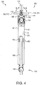
- the housing or handle 120 defines a front face or region depicted as F in Figure 2 , an oppositely directed rear face or region depicted as R in Figure 2 , and sides S1 and S2 generally extending between the front and rear faces as shown in Figure 4 .
- the gripping region 125 is a region along the outer surface of a front face of the housing or handle 120 that is configured to promote gripping by a user.
- the gripping region 125 includes a plurality of alternating ridges 125a and depressions 125b (best shown in Figure 2 ).
- the basin wrench 100 also comprises a swivel handle 130 (described in greater detail herein) by which a user axially rotates the head 102 about a longitudinal axis defined by the handle 120 and/or the support assembly 150.
- the longitudinal axis is illustrated in Figure 2 as LA.
- the swivel handle 130 is a T-bar swivel handle located at a proximal end 134 of the handle 120 and/or the support assembly 150.
- a user employs the swivel handle 130 as a lever to apply axial torque to the handle 120 and/or the support 150 and the rotational torque is transferred to the head 102, which, in turn, applies a wrenching torque to a nut, for example.
- the pivotal action of the jaws 110, 112 is further described.
- the jaws 110, 112 also pivot in the direction of arrows B in Figure 4 .
- the lower jaw 110 is pivotally attached to the head 116 and/or the distal end 118 of the housing, handle 120, and/or the support 150 by a pivot pin (not shown) or other member.
- the lower jaw 110 is pivotally movable in the direction of arrows B shown in Figure 4 .
- the axis of pivoting of the lower jaw 110 relative to the handle 120 and/or support 150 is perpendicular to the axis of pivoting of the upper jaw 112 relative to the lower jaw 110 via pivot pin 122.
- the axis of pivoting of the lower jaw 110 relative to the handle 120 and/or support 150 is also perpendicular to the longitudinal axis LA.
- the lower jaw 110 may be pivotally positioned through an angle of about 180° as shown in Figure 4
- the upper jaw 112 is carried with the lower jaw 110 via its attachment from the pivot pin 122.
- both the upper jaw and the lower jaw 110 are pivotally positionable in the direction of arrows B.
- One or more springs or other biasing members or biasing assemblies can be incorporated within the wrench 100 to bias the jaws 110, 112 to the position shown in Figure 4 in which the jaws 110, 112 generally extend along the longitudinal axis of the handle 120 and/or the support 150.
- the jaws 110, 112 are pivotally attached to one another so that the jaws can be positioned to a fully open state such as shown in Figure 6 in which the upper jaw 112 is angularly displaced approximately 180° apart from the lower jaw 110 as measured from axes taken with respect to their base portions, schematically depicted in Figure 6 as axes 110a and 112a.
- a light assembly 144 (see Figure 1 ) is incorporated within the handle 120.
- the light 144 is oriented to direct a light beam or other light pattern toward the head 102 to enhance the visibility of the area within which the user is working.
- the light 144 is configured such that upon emission of light, the emitted light irradiates at least a portion of the lower jaw 110 and the upper jaw 112.
- the light 144 can be battery operated and substantially thin and compact; although, this is not required.
- the light includes an LED element for emitting light.
- a commercially available 3V lithium battery designated as 2032 available from Eveready Battery under the ENERGIZER designation can be utilized for providing electrical power.
- Associated electronic circuitry and an actuation switch 145 are incorporated within the housing or handle 120.
- the switch 145 is provided along a rear face or region of the wrench 100.
- the light 144 can be configured to provide illumination for a preset time period to thereby preserve battery life in the event the operator neglects to turn the light off.
- a representative time period is from about 1 minute to about 10 minutes, and typically 5 minutes. It is also contemplated that the light 144 can be configured to flash prior to approaching expiration of the time period to indicate to the operator that the light will turn off shortly.
- the light assembly 144 includes intensity adjustment provisions such that a user can select between different levels of light intensity.
- the light 144 can be configured to provide two intensity levels such as "high” and "medium.” A greater number of intensity levels may also be provided. Alternatively, the light could utilize a single intensity level.
- the light 144 and associated components are retained within the handle 120 within a dedicated interior compartment which can be accessed by removal of fasteners 146 ( Figure 4 ) for example. The battery can also be accessed such as for replacement via removal of the fasteners 146. It should be appreciated that other suitable retaining means known in the art may, alternatively, be used for incorporating the light 144 within the handle 120.
- the frontwardly directed gripping region 125 can be adapted to include an actuator or push button switch (not shown) which is electrically connected to the light 144, instead of the previously noted rearwardly directed switch 145. Depression of a button along the gripping region 125 actuates the light, and the light 144 can direct a light beam toward the head 102 to enhance the visibility of the area within which the user is working.
- an actuator or push button switch (not shown) which is electrically connected to the light 144, instead of the previously noted rearwardly directed switch 145. Depression of a button along the gripping region 125 actuates the light, and the light 144 can direct a light beam toward the head 102 to enhance the visibility of the area within which the user is working.
- the swivel handle 130 promotes gripping or handling of the wrench 100 by an operator to thereby apply torque to the head 102 of the wrench.
- the swivel handle 130 is in the form of a T-bar assembly including a hub 135 and a bar 136 which extends through and is slidingly disposed in an aperture 137 defined in the hub 135 (best shown in Figure 3 ).
- the bar 136 may be provided with thickened end regions or outwardly extending members that prevent separation of the bar from the hub aperture 137.
- the hub 135 of the T-bar assembly is pivotally attached to a proximal end 134 of the handle 120 and/or the support 150.
- the hub 135 is pivotally positionable about a pivot pin 138 and thus an axis defined by that pin which is perpendicular to both the axis about which the lower jaw 110 is pivotable and the longitudinal axis LA. More specifically, the hub can include an arm member 135a (see Figure 2 ) that is pivotally attached to a yolk 139 via the pivot pin 138. This configuration facilitates a compact storage position for the wrench 100 as follows.
- the swivel handle 130 is positionable between a use position such as depicted in Figure 5 and a stowed position such as shown in Figures 2-4 .
- the bar 136 is oriented to a position that is generally parallel to the longitudinal axis LA of the handle 120 and/or support 150, as depicted in Figures 2-4 .
- an axis defined by the aperture 137 is parallel or substantially so with the longitudinal axis LA.
- the length portion of the bar 136 that extends along the rear face R of the handle 120 contacts that face along the entirety of that portion.
- the hub 135 and its arm 135a are pivoted about the pin 138 to a position generally perpendicular to the longitudinal axis LA as shown in Figure 2 .
- the bar 136 is slidably displaced relative to the hub 135 such that at least a portion of the length of the bar 136 is positioned along a region of the handle and particularly along the rear face of the handle 120.
- at least a portion of the bar 136 is sufficiently close to one or more retaining provisions along a rear face of the handle 120 such that the swivel handle 130 is retained in its stowed position.
- a majority portion of the length of the bar 136 is positioned alongside the handle 120 and/or the support 150 as shown in Figures 2-4 .
- the swivel handle 130 is positioned to a stowed position in which the hub 135 is pivoted about the pin 138 such that an axis defined by the aperture 137 of the hub is parallel with the longitudinal axis LA.
- the bar 136 upon positioning the swivel handle 130 to a use position, the bar 136 is generally perpendicular to the longitudinal axis LA. And, upon positioning the swivel handle 130 to a stowed position, the bar 136 is generally parallel to the longitudinal axis LA.
- the representative embodiment basin wrench 100 also comprises retaining provisions for releasably retaining the bar 136 of the T-bar assembly or swivel handle 130 in a stowed position along a region of the handle 120 or support 150.
- the retaining provisions of the wrench 100 include one or more magnets disposed within the handle 120 and/or along the support 150 and positioned along a rear face or region of the handle 120 adjacent the bar 136 when the swivel handle and bar are in their stowed position.
- Figures 2-5 illustrate one or more, and particularly a pair, of magnets 152 located along a rear face or region of the handle 120 and proximate the bar 136 when stowed.
- the magnets 152 are located or otherwise positioned such that upon placing the swivel handle 130 in its stowed position, at least a portion of the bar 136 (if including one or more ferromagnetic materials such as iron) is urged or otherwise pulled toward the magnet(s) 152.
- the wrench 100 includes the support assembly 150 and a polymeric handle or handle assembly 120 formed or generally enclosing the support 150.
- the polymeric handle 120 is engaged with or otherwise secured to the support 150.
- the polymeric handle 120 is typically molded or otherwise formed to provide an attractive, aesthetically pleasing appearance and include one or more regions such as the previously described contoured gripping region 125.
- the handle 120 can incorporate the previously noted light assembly 144.
- the handle 120 can also include the one or more magnets 152 to magnetically retain the bar 136 of the swivel handle 130.
- the handle 130 can in certain embodiments be directly molded about the support assembly 150 such as for example using over-molding techniques.
- the handle 120 can be formed separately from the support assembly 150 such as by injection molding techniques, and then assembled about the support 150.
- a wide array of polymeric materials could be used for the handle or handle assembly 120, a glass filled nylon material has been found to be rugged, durable, and provide resistance to wear and impacts.
- Figure 5 illustrates the swivel handle 130 in a use position in which the hub 135 is pivoted so as to extend outward from the handle 120 generally along the longitudinal axis LA of the handle 120.
- the bar 136 is slidably positioned within the aperture 137 defined in the hub 135 such that equal or substantially equal lengths of the bar 136 extend outward from both sides of the hub 135.
- Rotation of the swivel handle 130 about the longitudinal axis LA of the handle 120 and/or support 150 results in rotation of the head 102 and thus the jaws 110, 112 also about the longitudinal axis LA.
- the swivel handle 130 is removable from the handle 120 and/or the support 150.
- the swivel handle 130 and the proximal end 134 of the wrench 100 can include a conventional 3/8 inch or 1/2 inch square socket drive configuration for example.
- the exposed end 134 of the wrench includes a square socket receiving region (not shown) at which a conventional ratchet, extension, and/or breaker bar could be engaged for applying torque to the wrench 100 about the longitudinal axis LA.
- the present subject matter includes a wide array of releasable engagement provisions between the swivel handle 130 and the proximal end 134 of the wrench.
- the basin wrench 100 includes length adjustment provisions configured to adjust a length of the handle 120 and/or the support 150.
- Figures 7-9 illustrate the basin wrench 100 in an extended, telescoped state in which an extension portion 155 retained within the handle 120 and/or the support 150, is extended outward therefrom.
- the extension portion 155 generally extends along the longitudinal axis LA.
- the handle 120 and/or the support 150, and the extension portion 155 are telescoped together to allow selective variation in the length/height of the basin wrench 100.
- the extension portion 155 is sized to be slidingly received within the handle 120 and/or the support 150.
- the length adjustment provisions involve the use of a thermoplastic rubber or some other high friction material that suitably binds against, for example, the interior of at least one of the handle/support and extension portion 155.
- the extension portion 155 can be at least partially coated with the high friction material, and movement of the extension portion 155 relative to the handle/support causes the high friction material to press against an interior wall of the handle/support and thereby bind the handle/support and extension portion 155.
- a spring loaded detent button 160 accessible along a front face of the handle 120 governs extension and/or retraction of the portion 155.
- the detent button 160 is engageable with a plurality of openings or apertures provided along the front face F of the handle 120.
- the apertures can be located in the depressions 125b, i.e. one aperture per depression.
- the outwardly biased detent button 160 is engageable with each of the spaced apart apertures such that as the extension portion 155 travels past a respective aperture, the detent button 160 is urged outward into the aperture thereby "locking" or retaining the selected linear position or length of the handle.
- the handle 120 and/or the support 150 may be provided with spaced openings arrayed along one side of the handle or support.
- the previously noted detent button 160 can be used to selectively engage the openings for establishing the length of the basin wrench 100.
- the extension portion 155 can include a toothed rack which runs a length of the extension portion 155.
- An end of the extension portion located in the body can include a stop (not shown) to limit extension of the handle beyond a predetermined length. The stop can also prevent the extension portion 155 from being separated from the body handle 120 and/or support 150.
- a locking pawl (not shown) can be used, which is connected to the end of the body handle/support for selectively engaging the rack.
- the locking pawl is a biasing, pivoting-mechanism having an end portion configured to engage the teeth of the rack.
- the end portion of the locking pawl is biased toward the rack. Engagement of the rack by the locking pawl prevents unintended movement of the extension portion relative to the handle/support. However, when the locking pawl is moved to a retracted position, the extension portion is free to move in and out of the body.
- a spur gear might be used with the toothed rack. Rotation of the spur gear via a knob provided on the handle/support could alter the extension of the handle/support and a handle lock can be used to lock (or disengage) such a gear, thereby locking the body and extension portion in place (relative to one another) as well.
- one or more threads are provided on an end of the extension portion 155 located in the body handle/support.
- the end 134 of the body handle 120 and/or support 150 can be configured to engage the thread(s), and rotation of the extension portion 155 about the longitudinal axis LA defined by the handle 120 changes a length/height of the handle.
- a stop can be provided on the handle and adapted to engage the extension portion and prevent further rotation of the extension portion during use of the basin wrench 100.
- the embodiments of the length adjustment mechanism described herein are by way of example only and alternative designs which allow for telescoping movement of the extension portion 155 relative to the body handle 120 and/or the support 150 are contemplated for the adjustment mechanism. It should also be appreciated that although the embodiment of the basin wrench 100 described herein includes a length adjustable extension portion 155, it should be understood that the scope of this disclosure includes embodiments of the basin wrench in which the extension portion 155 is not adjustable in length.
Landscapes
- Engineering & Computer Science (AREA)
- Mechanical Engineering (AREA)
- Details Of Spanners, Wrenches, And Screw Drivers And Accessories (AREA)
Description
- This application claims priority from
US provisional application serial No. 61/719,058 filed on October 26, 2012 - The present subject matter relates to hand tools and particularly those for use in plumbing applications. More specifically, the present subject matter relates to basin wrenches.
- Basin nuts used to secure kitchen and vanity faucets, kitchen spray hoses, toilet ballcocks and the like usually are located in confined areas that are difficult to engage with a wrench. Many plastic nuts have wings or flanges to facilitate turning of the nuts by hand. In many cases, however, it still is necessary to use a wrench with such nuts to ensure tightness and also to loosen nuts which may have become "frozen" in place either through over-tightening or as a result of dissolved salts or minerals in the water. For example, the space under sinks is very limited due to an enclosed area having a plurality of supply lines, a drain assembly and other such obstacles thus making simple operations like disconnecting a supply line difficult with wrenches that are positioned to extend perpendicular to the fitting. Removing an old faucet and installing a new one is typically very difficult without a basin wrench (also referred to as a faucet wrench). A basin wrench is a plumbing tool for removing and installing sink faucets and is often used in such instances. A basin wrench generally has a long handle that is directed upward from under a sink to turn nuts on fittings and faucets. A basin wrench is normally used to loosen or tighten locknuts for supply hoses attached to compression fittings.
- In order to remove/install a faucet on a working sink it is necessary to loosen/tighten nuts that are located underneath and behind the sink bowl. Not only is it necessary to twist one's body into a small space, an operator must typically lay on his or her back and limited working space exists around these locking nuts. Moreover, when working in such difficult to access positions, such as under sinks, it is usually dark and difficult to see. Thus, users are forced to provide some sort of lighting to enable them to see what they are doing. This is often accomplished by balancing a flashlight under the sink so that the light is focused on the desired location. However, such undertaking is cumbersome and many times results in the flashlight falling over. Also, it requires the user to carry a flashlight, in addition to all of the other tools, to the work location.
- Although basin wrenches are known in the art, most include one or more metal members as a handle and can be difficult to grasp particularly if water, oils, or other contaminants are deposited thereon. In addition, if an auxiliary cross handle is provided such as for facilitating rotation of the wrench, the outwardly extending cross handle renders the wrench difficult to store in a tool box or other small space.
- Although a variety of basin and faucet wrenches are known in the art, a need remains for a basin wrench that further promotes ease and convenience of use, facilitates engagement and gripping of fittings or other components, is relatively compact when not in use, and which ergonomically combines multiple features in a single device which can be economically manufactured.
- Examples of such tools can be found in documents
US4485702A andUS6260452B1 . - The difficulties and drawbacks associated with previously known tools are addressed in the present subject matter basin wrenches.
- In one aspect, the present subject matter provides a basin wrench comprising a telescoping support assembly according to
claim 1. - Further, the present subject matter provides a basin wrench comprising a telescoping support assembly. The telescoping support assembly defines a distal end and an opposite proximal end. The telescoping support assembly defines a longitudinal axis. The wrench also comprises a lower jaw pivotally attached to the distal end of the support assembly. The lower jaw is pivotable about a first axis that is perpendicular to the longitudinal axis of the support assembly. The wrench also comprises an upper jaw pivotally attached to the lower jaw. The wrench also comprises a T-bar assembly pivotally and removably attached to the proximal end of the support assembly. The T-bar assembly includes a hub defining an aperture extending through the hub and a bar slidingly disposed in the aperture of the hub. The hub of the T-bar assembly is pivotable about a second axis that is perpendicular to both (i) the first axis about which the lower jaw is pivotable, and (ii) the longitudinal axis of the support assembly. The wrench also comprises a housing generally enclosing the support assembly. The housing defines a gripping region. The housing is formed from a polymeric material. The wrench also comprises a light assembly incorporated within the housing and located such that upon emission of light from the light assembly, emitted light irradiates at least a portion of the lower jaw and the upper jaw.
- In yet another aspect, the present subject matter provides a basin wrench comprising a telescoping support assembly defining a distal end, a proximal end, and a longitudinal axis. The basin wrench also comprises a pair of jaws pivotally attached to each other. The pair of jaws are pivotally attached to the distal end of the telescoping support assembly. The wrench also comprises a polymeric housing generally enclosing the support assembly. The housing defines a front face, an oppositely directed rear face, a first side extending between the front face and the rear face, and a second side extending between the front face and the rear face. The front face includes a contoured gripping region. And, the basin wrench also comprises a swivel handle assembly pivotally and removably attached to the proximal end of the support assembly. The swivel handle assembly includes a hub that is pivotally and removably attached to the proximal end of the support assembly. The hub defines an aperture extending through the hub. The swivel handle assembly includes a bar slidably disposed in the aperture defined by the hub. The swivel handle is positionable between a use position in which the bar is perpendicular to the longitudinal axis of the support assembly and a stowed position in which the bar is parallel to the longitudinal axis of the support assembly.
-
-
Figure 1 is a schematic perspective view of an embodiment of a basin wrench in accordance with the present subject matter. -
Figure 2 is a schematic view of a side of the basin wrench depicted inFigure 1 , with a swivel handle in a stowed position. -
Figure 3 is a schematic view of another side of the basin wrench shown inFigure 1 , with the swivel handle in a stowed position. -
Figure 4 is a schematic view of a rear face of the basin wrench shown inFigure 1 , with the swivel handle in a stowed position. -
Figure 5 is a schematic view of a side of the basin wrench depicted inFigure 1 , with the swivel handle in a use position. -
Figure 6 is a schematic view of a side of the basin wrench depicted inFigure 1 , with a pivotal jaw in an open position. -
Figure 7 is a schematic view of a side of the basin wrench ofFigure 1 in an extended, telescoped state. -
Figure 8 is a schematic view of a front face of the basin wrench ofFigure 1 in the extended, telescoped state. -
Figure 9 is a schematic perspective view of the basin wrench ofFigure 1 in the extended, telescoped state. - It should be understood that the description and drawings herein are merely illustrative. In general, the figures of the exemplary basin wrench are not to scale. It will also be appreciated that the various identified components of the exemplary basin wrench disclosed herein are merely terms of art that may vary from one manufacturer to another.
- The exemplary basin wrench disclosed herein is useful for rotating fasteners, such as basin nuts that attach a faucet unit to a countertop, for example. The exemplary basin wrench is also useful in many other applications for example tightening 7/8 inch supply line nuts, plastic wing supply nuts, 1 inch supply line nuts (and nuts having other, for example metric, dimensions) and supply line shut-off valves. Accordingly, the present disclosure should not be limited to only a wrench for loosening basin nuts, but instead should be construed broadly.
- Referring now to the drawings, wherein like numerals refer to like parts throughout the several views,
Figures 1-9 illustrate a representative embodiment of abasin wrench 100 according to the present disclosure. Referring toFigures 1-4 , thebasin wrench 100 includes a pivotinghead 102 having anengagement member 104 for engaging an item being wrenched or otherwise engaged. Theengagement member 104 is provided with twoopposed jaws lower jaw 110 is pivotally affixed to ahead 116 extending from adistal end 118 of a housing or handle 120 or asupport assembly 150 generally enclosed within the housing, denoted by the dashed line inFigure 3 . Thesupport assembly 150 is described in greater detail herein. The second orupper jaw 112 is pivotally affixed to thefirst jaw 110 by apivot pin 122. The first and second jaws can be biased closed by a spring or other biasing member (not shown). Specifically, thesecond jaw 112 is pivotally movable about thepivot pin 122 in the direction of arrows A shown inFigure 2 . As with conventional basin wrenches, the first andsecond jaws - The
handle 120 includes afore segment 124, anaft segment 128, and a contouredgripping region 125. The housing or handle 120 defines a front face or region depicted as F inFigure 2 , an oppositely directed rear face or region depicted as R inFigure 2 , and sides S1 and S2 generally extending between the front and rear faces as shown inFigure 4 . In the illustrated embodiment, thegripping region 125 is a region along the outer surface of a front face of the housing or handle 120 that is configured to promote gripping by a user. In the depicted embodiment, thegripping region 125 includes a plurality of alternatingridges 125a anddepressions 125b (best shown inFigure 2 ). Thebasin wrench 100 also comprises a swivel handle 130 (described in greater detail herein) by which a user axially rotates thehead 102 about a longitudinal axis defined by thehandle 120 and/or thesupport assembly 150. The longitudinal axis is illustrated inFigure 2 as LA. In the embodiment illustrated herein, the swivel handle 130 is a T-bar swivel handle located at aproximal end 134 of thehandle 120 and/or thesupport assembly 150. In operation, a user employs the swivel handle 130 as a lever to apply axial torque to thehandle 120 and/or thesupport 150 and the rotational torque is transferred to thehead 102, which, in turn, applies a wrenching torque to a nut, for example. - Referring to
Figures 4-6 , the pivotal action of thejaws upper jaw 112 relative to thelower jaw 110 about thepivot pin 122 in the direction of arrows A inFigure 2 , thejaws Figure 4 . Specifically, thelower jaw 110 is pivotally attached to thehead 116 and/or thedistal end 118 of the housing, handle 120, and/or thesupport 150 by a pivot pin (not shown) or other member. Specifically, thelower jaw 110 is pivotally movable in the direction of arrows B shown inFigure 4 . The axis of pivoting of thelower jaw 110 relative to thehandle 120 and/orsupport 150 is perpendicular to the axis of pivoting of theupper jaw 112 relative to thelower jaw 110 viapivot pin 122. In certain embodiments, the axis of pivoting of thelower jaw 110 relative to thehandle 120 and/orsupport 150 is also perpendicular to the longitudinal axis LA. As thelower jaw 110 may be pivotally positioned through an angle of about 180° as shown inFigure 4 , theupper jaw 112 is carried with thelower jaw 110 via its attachment from thepivot pin 122. Thus, both the upper jaw and thelower jaw 110 are pivotally positionable in the direction of arrows B. One or more springs or other biasing members or biasing assemblies can be incorporated within thewrench 100 to bias thejaws Figure 4 in which thejaws handle 120 and/or thesupport 150. - As previously described, the
jaws Figure 6 in which theupper jaw 112 is angularly displaced approximately 180° apart from thelower jaw 110 as measured from axes taken with respect to their base portions, schematically depicted inFigure 6 asaxes - In certain embodiments such as the
wrench 100, a light assembly 144 (seeFigure 1 ) is incorporated within thehandle 120. The light 144 is oriented to direct a light beam or other light pattern toward thehead 102 to enhance the visibility of the area within which the user is working. Specifically, the light 144 is configured such that upon emission of light, the emitted light irradiates at least a portion of thelower jaw 110 and theupper jaw 112. The light 144 can be battery operated and substantially thin and compact; although, this is not required. In a particular version of the basin wrench, the light includes an LED element for emitting light. A commercially available 3V lithium battery designated as 2032 available from Eveready Battery under the ENERGIZER designation can be utilized for providing electrical power. Associated electronic circuitry and an actuation switch 145 (seeFigure 4 ) are incorporated within the housing or handle 120. In this embodiment, theswitch 145 is provided along a rear face or region of thewrench 100. The light 144 can be configured to provide illumination for a preset time period to thereby preserve battery life in the event the operator neglects to turn the light off. A representative time period is from about 1 minute to about 10 minutes, and typically 5 minutes. It is also contemplated that the light 144 can be configured to flash prior to approaching expiration of the time period to indicate to the operator that the light will turn off shortly. In certain versions of the basin wrench, thelight assembly 144 includes intensity adjustment provisions such that a user can select between different levels of light intensity. For example, the light 144 can be configured to provide two intensity levels such as "high" and "medium." A greater number of intensity levels may also be provided. Alternatively, the light could utilize a single intensity level. In therepresentative embodiment 100, the light 144 and associated components are retained within thehandle 120 within a dedicated interior compartment which can be accessed by removal of fasteners 146 (Figure 4 ) for example. The battery can also be accessed such as for replacement via removal of thefasteners 146. It should be appreciated that other suitable retaining means known in the art may, alternatively, be used for incorporating the light 144 within thehandle 120. - It is also contemplated that the frontwardly directed
gripping region 125 can be adapted to include an actuator or push button switch (not shown) which is electrically connected to the light 144, instead of the previously noted rearwardly directedswitch 145. Depression of a button along thegripping region 125 actuates the light, and the light 144 can direct a light beam toward thehead 102 to enhance the visibility of the area within which the user is working. - As previously described, the swivel handle 130 promotes gripping or handling of the
wrench 100 by an operator to thereby apply torque to thehead 102 of the wrench. In the particular embodiment illustrated and described herein, the swivel handle 130 is in the form of a T-bar assembly including ahub 135 and abar 136 which extends through and is slidingly disposed in anaperture 137 defined in the hub 135 (best shown inFigure 3 ). Thebar 136 may be provided with thickened end regions or outwardly extending members that prevent separation of the bar from thehub aperture 137. Thehub 135 of the T-bar assembly is pivotally attached to aproximal end 134 of thehandle 120 and/or thesupport 150. Thehub 135 is pivotally positionable about apivot pin 138 and thus an axis defined by that pin which is perpendicular to both the axis about which thelower jaw 110 is pivotable and the longitudinal axis LA. More specifically, the hub can include anarm member 135a (seeFigure 2 ) that is pivotally attached to ayolk 139 via thepivot pin 138. This configuration facilitates a compact storage position for thewrench 100 as follows. - In a particular version of the present subject matter, the swivel handle 130 is positionable between a use position such as depicted in
Figure 5 and a stowed position such as shown inFigures 2-4 . When the swivel handle 130 is placed in its stowed position, thebar 136 is oriented to a position that is generally parallel to the longitudinal axis LA of thehandle 120 and/orsupport 150, as depicted inFigures 2-4 . In this stowed position, an axis defined by theaperture 137 is parallel or substantially so with the longitudinal axis LA. In certain embodiments, the length portion of thebar 136 that extends along the rear face R of thehandle 120 contacts that face along the entirety of that portion. Specifically, in positioning the swivel handle 130 to its stowed position, thehub 135 and itsarm 135a are pivoted about thepin 138 to a position generally perpendicular to the longitudinal axis LA as shown inFigure 2 . Thebar 136 is slidably displaced relative to thehub 135 such that at least a portion of the length of thebar 136 is positioned along a region of the handle and particularly along the rear face of thehandle 120. In certain embodiments, at least a portion of thebar 136 is sufficiently close to one or more retaining provisions along a rear face of thehandle 120 such that the swivel handle 130 is retained in its stowed position. In particular embodiments such as shown in the referenced figures, a majority portion of the length of thebar 136 is positioned alongside thehandle 120 and/or thesupport 150 as shown inFigures 2-4 . In such embodiments, the swivel handle 130 is positioned to a stowed position in which thehub 135 is pivoted about thepin 138 such that an axis defined by theaperture 137 of the hub is parallel with the longitudinal axis LA. - In certain embodiments, upon positioning the swivel handle 130 to a use position, the
bar 136 is generally perpendicular to the longitudinal axis LA. And, upon positioning the swivel handle 130 to a stowed position, thebar 136 is generally parallel to the longitudinal axis LA. - The representative
embodiment basin wrench 100 also comprises retaining provisions for releasably retaining thebar 136 of the T-bar assembly or swivel handle 130 in a stowed position along a region of thehandle 120 orsupport 150. In certain versions of thewrench 100, the retaining provisions of thewrench 100 include one or more magnets disposed within thehandle 120 and/or along thesupport 150 and positioned along a rear face or region of thehandle 120 adjacent thebar 136 when the swivel handle and bar are in their stowed position.Figures 2-5 illustrate one or more, and particularly a pair, ofmagnets 152 located along a rear face or region of thehandle 120 and proximate thebar 136 when stowed. Themagnets 152 are located or otherwise positioned such that upon placing the swivel handle 130 in its stowed position, at least a portion of the bar 136 (if including one or more ferromagnetic materials such as iron) is urged or otherwise pulled toward the magnet(s) 152. - In certain embodiments, the
wrench 100 includes thesupport assembly 150 and a polymeric handle or handleassembly 120 formed or generally enclosing thesupport 150. Typically, thepolymeric handle 120 is engaged with or otherwise secured to thesupport 150. Thepolymeric handle 120 is typically molded or otherwise formed to provide an attractive, aesthetically pleasing appearance and include one or more regions such as the previously described contouredgripping region 125. Thehandle 120 can incorporate the previously notedlight assembly 144. Thehandle 120 can also include the one ormore magnets 152 to magnetically retain thebar 136 of theswivel handle 130. Thehandle 130 can in certain embodiments be directly molded about thesupport assembly 150 such as for example using over-molding techniques. Alternatively, thehandle 120 can be formed separately from thesupport assembly 150 such as by injection molding techniques, and then assembled about thesupport 150. Although a wide array of polymeric materials could be used for the handle or handleassembly 120, a glass filled nylon material has been found to be rugged, durable, and provide resistance to wear and impacts. -
Figure 5 illustrates the swivel handle 130 in a use position in which thehub 135 is pivoted so as to extend outward from thehandle 120 generally along the longitudinal axis LA of thehandle 120. Thebar 136 is slidably positioned within theaperture 137 defined in thehub 135 such that equal or substantially equal lengths of thebar 136 extend outward from both sides of thehub 135. Rotation of the swivel handle 130 about the longitudinal axis LA of thehandle 120 and/orsupport 150 results in rotation of thehead 102 and thus thejaws - In certain embodiments the swivel handle 130 is removable from the
handle 120 and/or thesupport 150. The swivel handle 130 and theproximal end 134 of thewrench 100 can include a conventional 3/8 inch or 1/2 inch square socket drive configuration for example. Upon disengagement of the swivel handle 130 from theproximal end 134, theexposed end 134 of the wrench includes a square socket receiving region (not shown) at which a conventional ratchet, extension, and/or breaker bar could be engaged for applying torque to thewrench 100 about the longitudinal axis LA. The present subject matter includes a wide array of releasable engagement provisions between the swivel handle 130 and theproximal end 134 of the wrench. - The
basin wrench 100 includes length adjustment provisions configured to adjust a length of thehandle 120 and/or thesupport 150.Figures 7-9 illustrate thebasin wrench 100 in an extended, telescoped state in which anextension portion 155 retained within thehandle 120 and/or thesupport 150, is extended outward therefrom. Theextension portion 155 generally extends along the longitudinal axis LA. Particularly, thehandle 120 and/or thesupport 150, and theextension portion 155 are telescoped together to allow selective variation in the length/height of thebasin wrench 100. As shown, theextension portion 155 is sized to be slidingly received within thehandle 120 and/or thesupport 150. In the embodiment shown inFigures 7-9 , the length adjustment provisions involve the use of a thermoplastic rubber or some other high friction material that suitably binds against, for example, the interior of at least one of the handle/support andextension portion 155. For example, theextension portion 155 can be at least partially coated with the high friction material, and movement of theextension portion 155 relative to the handle/support causes the high friction material to press against an interior wall of the handle/support and thereby bind the handle/support andextension portion 155. A spring loadeddetent button 160 accessible along a front face of thehandle 120 governs extension and/or retraction of theportion 155. In thewrench embodiment 100, thedetent button 160 is engageable with a plurality of openings or apertures provided along the front face F of thehandle 120. As illustrated inFigures 2 and9 for example, the apertures can be located in thedepressions 125b, i.e. one aperture per depression. The outwardlybiased detent button 160 is engageable with each of the spaced apart apertures such that as theextension portion 155 travels past a respective aperture, thedetent button 160 is urged outward into the aperture thereby "locking" or retaining the selected linear position or length of the handle. - In alternate embodiments, to adjust the overall length of the
wrench 100, thehandle 120 and/or thesupport 150 may be provided with spaced openings arrayed along one side of the handle or support. The previously noteddetent button 160 can be used to selectively engage the openings for establishing the length of thebasin wrench 100. To allow for incremental adjustment in length of thehandle 120 and/orsupport 150, and according to another alternate embodiment of the adjustment mechanism, theextension portion 155 can include a toothed rack which runs a length of theextension portion 155. An end of the extension portion located in the body can include a stop (not shown) to limit extension of the handle beyond a predetermined length. The stop can also prevent theextension portion 155 from being separated from the body handle 120 and/orsupport 150. A locking pawl (not shown) can be used, which is connected to the end of the body handle/support for selectively engaging the rack. The locking pawl is a biasing, pivoting-mechanism having an end portion configured to engage the teeth of the rack. The end portion of the locking pawl is biased toward the rack. Engagement of the rack by the locking pawl prevents unintended movement of the extension portion relative to the handle/support. However, when the locking pawl is moved to a retracted position, the extension portion is free to move in and out of the body. - In still another alternative embodiment of the adjustment mechanism, instead of the locking pawl, a spur gear might be used with the toothed rack. Rotation of the spur gear via a knob provided on the handle/support could alter the extension of the handle/support and a handle lock can be used to lock (or disengage) such a gear, thereby locking the body and extension portion in place (relative to one another) as well.
- In still another alternate embodiment of the adjustment mechanism, one or more threads are provided on an end of the
extension portion 155 located in the body handle/support. Theend 134 of the body handle 120 and/orsupport 150 can be configured to engage the thread(s), and rotation of theextension portion 155 about the longitudinal axis LA defined by thehandle 120 changes a length/height of the handle. A stop can be provided on the handle and adapted to engage the extension portion and prevent further rotation of the extension portion during use of thebasin wrench 100. - It should be appreciated that the embodiments of the length adjustment mechanism described herein are by way of example only and alternative designs which allow for telescoping movement of the
extension portion 155 relative to the body handle 120 and/or thesupport 150 are contemplated for the adjustment mechanism. It should also be appreciated that although the embodiment of thebasin wrench 100 described herein includes a lengthadjustable extension portion 155, it should be understood that the scope of this disclosure includes embodiments of the basin wrench in which theextension portion 155 is not adjustable in length. - Many other benefits will no doubt become apparent from future application and development of this technology.
Claims (5)
- A basin wrench (100) comprising:a telescoping support assembly (150), including an extension portion (155), the support (150) defining a distal end (118) and an opposite proximal end (134), the telescoping support (150) defining a longitudinal axis;a head (116) extending from the distal end (118) of the support;a lower jaw (110) pivotally attached to the head (116), the lower jaw (110) pivotable about a first axis that is perpendicular to the longitudinal axis of the support;an upper jaw (112) pivotally attached to the lower jaw (110);a T-bar assembly (130) pivotally and removably attached to the proximal end (134) of the support (150), the T-bar assembly (130) including a hub (135) defining an aperture (137) extending through the hub (135) and a bar (136) slidingly disposed in the aperture (137) of the hub (135);a housing (120) generally enclosing the support assembly (150), the housing (120) defining a fore segment located proximate the distal end (118) of the support and an aft segment located adjacent the proximal end of the support, the housing (120) also defining a contoured gripping region (125), and the extension portion (155) being seized to be slidingly received within the housing (120);wherein the hub (135) of the T-bar assembly (130) is pivotable about a second axis that is perpendicular to both(i) the first axis about which the lower jaw (110) is pivotable relative to the head (116), and(ii) the longitudinal axis of the support; and whereinthe T-bar assembly (130) is positionable to a stowed position in which the hub (135) is pivoted about the second axis so that a third axis defined by the aperture (137) of the hub (135) is parallel with the longitudinal axis of the support, andthe bar (136) of the T-bar assembly is displaced relative to the hub (135) so that a majority portion of a length of the bar (136) is positioned alongside the housing (120), and that length portion of the bar contacts the housing (120) along the entirety of that portion
- The basin wrench of claim 1 wherein the housing (120) is formed from a polymeric material, the basin wrench (100) further comprising:
at least one magnet (152) disposed within the housing (120) and located such that upon positioning the T-bar assembly (130) to a stowed position, the bar (136) is magnetically retained along the housing (120). - The basin wrench of claim 1 wherein
the housing (120) is formed from a polymeric material,
the bar (136) includes a ferromagnetic material,
the housing (120) includes at least one magnet (152) disposed within the housing (120),
the T-bar assembly (130) is positionable to a stowed position in which the hub (135) is pivoted about the second axis so that a third axis defined by the aperture (137) of the hub (135) is parallel with the longitudinal axis of the support, and
the bar (136) of the T-bar assembly (130) is displaced relative to the hub (135) so that a majority portion of a length of the bar (136) is positioned alongside the housing (120), and
the at least one magnet (152) disposed in the housing (120) is located sufficiently close to the bar (136) positioned alongside the housing (120) such that the bar (136) is magnetically retained alongside the housing (120). - The basin wrench of claim 1 further comprising:a light assembly (144) including an electrically operated light source, at least one battery, and electrical circuitry, whereinthe light assembly is incorporated within the basin wrench (100) and the light source is oriented so as to direct light emitted therefrom towards the lower jaw (110) and the upper jaw (112).
- The basin wrench of claim 1 wherein the T-bar assembly (130) is disengageable and separable from the proximal end (134) of the support (150).
Applications Claiming Priority (2)
| Application Number | Priority Date | Filing Date | Title |
|---|---|---|---|
| US201261719058P | 2012-10-26 | 2012-10-26 | |
| PCT/US2013/066760 WO2014066732A1 (en) | 2012-10-26 | 2013-10-25 | Basin wrench |
Publications (3)
| Publication Number | Publication Date |
|---|---|
| EP2911828A1 EP2911828A1 (en) | 2015-09-02 |
| EP2911828A4 EP2911828A4 (en) | 2016-09-07 |
| EP2911828B1 true EP2911828B1 (en) | 2019-08-07 |
Family
ID=50545298
Family Applications (1)
| Application Number | Title | Priority Date | Filing Date |
|---|---|---|---|
| EP13848146.0A Active EP2911828B1 (en) | 2012-10-26 | 2013-10-25 | Basin wrench |
Country Status (4)
| Country | Link |
|---|---|
| US (1) | US9616555B2 (en) |
| EP (1) | EP2911828B1 (en) |
| AU (1) | AU2013334217A1 (en) |
| WO (1) | WO2014066732A1 (en) |
Families Citing this family (13)
| Publication number | Priority date | Publication date | Assignee | Title |
|---|---|---|---|---|
| US11235443B2 (en) | 2013-03-26 | 2022-02-01 | Milwaukee Electric Tool Corporation | Pipe wrench |
| EP3186038B1 (en) * | 2014-08-27 | 2022-07-20 | Milwaukee Electric Tool Corporation | Pipe wrench |
| USD773909S1 (en) | 2015-10-14 | 2016-12-13 | Cheyenne Paddock | Faucet wrench |
| TWI583511B (en) * | 2016-01-22 | 2017-05-21 | yu-xiang Huang | Body structure |
| US10666007B2 (en) | 2017-04-25 | 2020-05-26 | Bae Systems Information And Electronic Systems Integration Inc. | Cable connector tool |
| WO2019191655A1 (en) | 2018-03-30 | 2019-10-03 | Milwaukee Electric Tool Corporation | Pipe wrench |
| US11865677B2 (en) | 2018-04-21 | 2024-01-09 | Jeffrey Dean MacDonald | Ratcheting wrenches, wrench systems, sockets, and methods of use |
| CN108890565A (en) * | 2018-09-20 | 2018-11-27 | 广东电网有限责任公司 | A kind of screw knife assembly |
| TWI702120B (en) * | 2019-11-28 | 2020-08-21 | 和嘉興精密股份有限公司 | Torsion structure |
| US20220018117A1 (en) * | 2020-07-17 | 2022-01-20 | Mario David Bertorelli | Jimmy twist wrench with shaft and handle apparatus and a method of using same |
| EP4192651A4 (en) | 2020-08-04 | 2024-12-11 | Milwaukee Electric Tool Corporation | EXTENDABLE WRENCH |
| US12138749B2 (en) | 2022-03-07 | 2024-11-12 | Francisco Salas | Basin wrench assembly |
| US20230390902A1 (en) * | 2022-06-02 | 2023-12-07 | Raymond Leroy Black, Jr. | Powered ratchet wrench |
Citations (1)
| Publication number | Priority date | Publication date | Assignee | Title |
|---|---|---|---|---|
| US6945145B1 (en) * | 2003-10-17 | 2005-09-20 | Kesinger Donald A | Quick action tap wrench |
Family Cites Families (17)
| Publication number | Priority date | Publication date | Assignee | Title |
|---|---|---|---|---|
| US1795048A (en) * | 1930-07-07 | 1931-03-03 | Otto H Schuh | Basin wrench |
| US2166449A (en) * | 1938-12-27 | 1939-07-18 | Sharpe Louis | Basin wrench |
| US2491623A (en) | 1947-09-19 | 1949-12-20 | Steven G Sesak | Basin wrench having rotatably adjustable inner jaw and multiaxispivoted outer jaw |
| US4485702A (en) * | 1981-03-03 | 1984-12-04 | William C. Swan | Positive action basin wrench |
| US5595095A (en) * | 1994-10-13 | 1997-01-21 | Hillinger; George | Ratcheting socket wrench with intermeshing gears |
| US6135607A (en) * | 1997-12-11 | 2000-10-24 | Cook; Jesse James | Lightweight angular tool extending apparatus and light |
| US6477921B1 (en) | 1999-11-01 | 2002-11-12 | John A. Picone | Anti-jamming coupling device for powered adjustable wrench |
| US6260452B1 (en) * | 2000-12-27 | 2001-07-17 | Hsiu-E Yu | Two-axle tool |
| TW554797U (en) * | 2003-01-21 | 2003-09-21 | Shiue-Chin Jang | Improved structure of spanner handle |
| WO2005030440A1 (en) | 2003-09-26 | 2005-04-07 | W.J. Technologies, Llc | Basin wrench |
| US7121172B1 (en) * | 2004-05-24 | 2006-10-17 | Joseph Daniels | Dual-headed ratcheting basin wrench |
| US20070256237A1 (en) | 2004-12-10 | 2007-11-08 | Mayer Robert H | System and method for attaching a drain assembly to a plumbing fixture |
| US20060207393A1 (en) * | 2005-03-17 | 2006-09-21 | Stupar Joe A | Wrench |
| US20080034927A1 (en) | 2006-08-04 | 2008-02-14 | Emerson Electric Co. | Basin wrench |
| FR2913076B1 (en) * | 2007-02-26 | 2010-10-22 | Pellenc Sa | CLAMPING DEVICE WITH RETRACTABLE SHAFT ARM AND APPARATUS INCLUDING THE SAME |
| US8387490B2 (en) * | 2011-04-01 | 2013-03-05 | Hong-Jen Lee | Tool with pivotable and slidable handles |
| US9381628B1 (en) * | 2013-07-03 | 2016-07-05 | Roy J. Garza | Wrench with adjustable length handle |
-
2013
- 2013-10-23 US US14/061,021 patent/US9616555B2/en active Active
- 2013-10-25 EP EP13848146.0A patent/EP2911828B1/en active Active
- 2013-10-25 WO PCT/US2013/066760 patent/WO2014066732A1/en not_active Ceased
- 2013-10-25 AU AU2013334217A patent/AU2013334217A1/en not_active Abandoned
Patent Citations (1)
| Publication number | Priority date | Publication date | Assignee | Title |
|---|---|---|---|---|
| US6945145B1 (en) * | 2003-10-17 | 2005-09-20 | Kesinger Donald A | Quick action tap wrench |
Also Published As
| Publication number | Publication date |
|---|---|
| WO2014066732A1 (en) | 2014-05-01 |
| WO2014066732A4 (en) | 2014-06-26 |
| EP2911828A4 (en) | 2016-09-07 |
| AU2013334217A1 (en) | 2015-04-02 |
| US9616555B2 (en) | 2017-04-11 |
| EP2911828A1 (en) | 2015-09-02 |
| US20140116206A1 (en) | 2014-05-01 |
Similar Documents
| Publication | Publication Date | Title |
|---|---|---|
| US9616555B2 (en) | Basin wrench | |
| US10343273B2 (en) | Dual purpose flip-out and T handle | |
| US6890135B2 (en) | Power tool with light emitting diode | |
| US6499172B1 (en) | Power tool adjustable handle assembly | |
| US9339938B2 (en) | Powered cutting tool | |
| US20100319138A1 (en) | Portable tool kit with auto-release clasp and expandable tools | |
| US8485073B1 (en) | Viper crescent wrench device | |
| US9174333B2 (en) | Portable tool | |
| US20110215539A1 (en) | Power tool and chuck release tool | |
| US9216503B2 (en) | Multi-tool wrench | |
| US6732615B2 (en) | Multiple-size nut driver | |
| AU2008201152A1 (en) | Wrench | |
| CN101253015A (en) | power tool | |
| WO2007089915A2 (en) | Multi function tool | |
| US5926913A (en) | Pneumatic tool extension | |
| US5870932A (en) | Swift wrench | |
| US5746099A (en) | Adjustable open-wrench with a sliding side jaw having a releasable adjustment mechanism to allow ratcheting operation | |
| EP2844432A1 (en) | Open-ended ratchet wrench | |
| CN103501972B (en) | Power driven cutter | |
| US20140116208A1 (en) | Pipe wrench or water pump wrench | |
| US4580468A (en) | Pipe wrench | |
| KR101955954B1 (en) | All-in-one united driver | |
| US20110116882A1 (en) | Inner and outer thread tapping tool | |
| US9993911B1 (en) | Wrench system; side loading, insert using, ratcheting, open end, pass through, socket, quick changing, fastener retaining, reversible, manual or powered, variable high speed, torque sensing, flare nut | |
| US20240100659A1 (en) | Wrenches |
Legal Events
| Date | Code | Title | Description |
|---|---|---|---|
| PUAI | Public reference made under article 153(3) epc to a published international application that has entered the european phase |
Free format text: ORIGINAL CODE: 0009012 |
|
| 17P | Request for examination filed |
Effective date: 20150324 |
|
| AK | Designated contracting states |
Kind code of ref document: A1 Designated state(s): AL AT BE BG CH CY CZ DE DK EE ES FI FR GB GR HR HU IE IS IT LI LT LU LV MC MK MT NL NO PL PT RO RS SE SI SK SM TR |
|
| AX | Request for extension of the european patent |
Extension state: BA ME |
|
| DAX | Request for extension of the european patent (deleted) | ||
| RA4 | Supplementary search report drawn up and despatched (corrected) |
Effective date: 20160809 |
|
| RIC1 | Information provided on ipc code assigned before grant |
Ipc: B25B 13/48 20060101ALI20160803BHEP Ipc: B25B 13/00 20060101AFI20160803BHEP Ipc: B25B 23/18 20060101ALI20160803BHEP Ipc: B25B 13/50 20060101ALI20160803BHEP Ipc: B25G 1/00 20060101ALI20160803BHEP |
|
| STAA | Information on the status of an ep patent application or granted ep patent |
Free format text: STATUS: EXAMINATION IS IN PROGRESS |
|
| 17Q | First examination report despatched |
Effective date: 20171006 |
|
| GRAP | Despatch of communication of intention to grant a patent |
Free format text: ORIGINAL CODE: EPIDOSNIGR1 |
|
| STAA | Information on the status of an ep patent application or granted ep patent |
Free format text: STATUS: GRANT OF PATENT IS INTENDED |
|
| INTG | Intention to grant announced |
Effective date: 20190322 |
|
| GRAS | Grant fee paid |
Free format text: ORIGINAL CODE: EPIDOSNIGR3 |
|
| GRAA | (expected) grant |
Free format text: ORIGINAL CODE: 0009210 |
|
| STAA | Information on the status of an ep patent application or granted ep patent |
Free format text: STATUS: THE PATENT HAS BEEN GRANTED |
|
| AK | Designated contracting states |
Kind code of ref document: B1 Designated state(s): AL AT BE BG CH CY CZ DE DK EE ES FI FR GB GR HR HU IE IS IT LI LT LU LV MC MK MT NL NO PL PT RO RS SE SI SK SM TR |
|
| REG | Reference to a national code |
Ref country code: GB Ref legal event code: FG4D |
|
| REG | Reference to a national code |
Ref country code: CH Ref legal event code: EP Ref country code: AT Ref legal event code: REF Ref document number: 1163106 Country of ref document: AT Kind code of ref document: T Effective date: 20190815 |
|
| REG | Reference to a national code |
Ref country code: DE Ref legal event code: R096 Ref document number: 602013058948 Country of ref document: DE |
|
| REG | Reference to a national code |
Ref country code: IE Ref legal event code: FG4D |
|
| REG | Reference to a national code |
Ref country code: NL Ref legal event code: MP Effective date: 20190807 |
|
| REG | Reference to a national code |
Ref country code: LT Ref legal event code: MG4D |
|
| PG25 | Lapsed in a contracting state [announced via postgrant information from national office to epo] |
Ref country code: LT Free format text: LAPSE BECAUSE OF FAILURE TO SUBMIT A TRANSLATION OF THE DESCRIPTION OR TO PAY THE FEE WITHIN THE PRESCRIBED TIME-LIMIT Effective date: 20190807 Ref country code: HR Free format text: LAPSE BECAUSE OF FAILURE TO SUBMIT A TRANSLATION OF THE DESCRIPTION OR TO PAY THE FEE WITHIN THE PRESCRIBED TIME-LIMIT Effective date: 20190807 Ref country code: BG Free format text: LAPSE BECAUSE OF FAILURE TO SUBMIT A TRANSLATION OF THE DESCRIPTION OR TO PAY THE FEE WITHIN THE PRESCRIBED TIME-LIMIT Effective date: 20191107 Ref country code: NL Free format text: LAPSE BECAUSE OF FAILURE TO SUBMIT A TRANSLATION OF THE DESCRIPTION OR TO PAY THE FEE WITHIN THE PRESCRIBED TIME-LIMIT Effective date: 20190807 Ref country code: PT Free format text: LAPSE BECAUSE OF FAILURE TO SUBMIT A TRANSLATION OF THE DESCRIPTION OR TO PAY THE FEE WITHIN THE PRESCRIBED TIME-LIMIT Effective date: 20191209 Ref country code: NO Free format text: LAPSE BECAUSE OF FAILURE TO SUBMIT A TRANSLATION OF THE DESCRIPTION OR TO PAY THE FEE WITHIN THE PRESCRIBED TIME-LIMIT Effective date: 20191107 Ref country code: FI Free format text: LAPSE BECAUSE OF FAILURE TO SUBMIT A TRANSLATION OF THE DESCRIPTION OR TO PAY THE FEE WITHIN THE PRESCRIBED TIME-LIMIT Effective date: 20190807 Ref country code: SE Free format text: LAPSE BECAUSE OF FAILURE TO SUBMIT A TRANSLATION OF THE DESCRIPTION OR TO PAY THE FEE WITHIN THE PRESCRIBED TIME-LIMIT Effective date: 20190807 |
|
| REG | Reference to a national code |
Ref country code: AT Ref legal event code: MK05 Ref document number: 1163106 Country of ref document: AT Kind code of ref document: T Effective date: 20190807 |
|
| PG25 | Lapsed in a contracting state [announced via postgrant information from national office to epo] |
Ref country code: IS Free format text: LAPSE BECAUSE OF FAILURE TO SUBMIT A TRANSLATION OF THE DESCRIPTION OR TO PAY THE FEE WITHIN THE PRESCRIBED TIME-LIMIT Effective date: 20191207 Ref country code: RS Free format text: LAPSE BECAUSE OF FAILURE TO SUBMIT A TRANSLATION OF THE DESCRIPTION OR TO PAY THE FEE WITHIN THE PRESCRIBED TIME-LIMIT Effective date: 20190807 Ref country code: GR Free format text: LAPSE BECAUSE OF FAILURE TO SUBMIT A TRANSLATION OF THE DESCRIPTION OR TO PAY THE FEE WITHIN THE PRESCRIBED TIME-LIMIT Effective date: 20191108 Ref country code: ES Free format text: LAPSE BECAUSE OF FAILURE TO SUBMIT A TRANSLATION OF THE DESCRIPTION OR TO PAY THE FEE WITHIN THE PRESCRIBED TIME-LIMIT Effective date: 20190807 Ref country code: AL Free format text: LAPSE BECAUSE OF FAILURE TO SUBMIT A TRANSLATION OF THE DESCRIPTION OR TO PAY THE FEE WITHIN THE PRESCRIBED TIME-LIMIT Effective date: 20190807 Ref country code: LV Free format text: LAPSE BECAUSE OF FAILURE TO SUBMIT A TRANSLATION OF THE DESCRIPTION OR TO PAY THE FEE WITHIN THE PRESCRIBED TIME-LIMIT Effective date: 20190807 |
|
| PG25 | Lapsed in a contracting state [announced via postgrant information from national office to epo] |
Ref country code: TR Free format text: LAPSE BECAUSE OF FAILURE TO SUBMIT A TRANSLATION OF THE DESCRIPTION OR TO PAY THE FEE WITHIN THE PRESCRIBED TIME-LIMIT Effective date: 20190807 |
|
| PG25 | Lapsed in a contracting state [announced via postgrant information from national office to epo] |
Ref country code: AT Free format text: LAPSE BECAUSE OF FAILURE TO SUBMIT A TRANSLATION OF THE DESCRIPTION OR TO PAY THE FEE WITHIN THE PRESCRIBED TIME-LIMIT Effective date: 20190807 Ref country code: EE Free format text: LAPSE BECAUSE OF FAILURE TO SUBMIT A TRANSLATION OF THE DESCRIPTION OR TO PAY THE FEE WITHIN THE PRESCRIBED TIME-LIMIT Effective date: 20190807 Ref country code: DK Free format text: LAPSE BECAUSE OF FAILURE TO SUBMIT A TRANSLATION OF THE DESCRIPTION OR TO PAY THE FEE WITHIN THE PRESCRIBED TIME-LIMIT Effective date: 20190807 Ref country code: IT Free format text: LAPSE BECAUSE OF FAILURE TO SUBMIT A TRANSLATION OF THE DESCRIPTION OR TO PAY THE FEE WITHIN THE PRESCRIBED TIME-LIMIT Effective date: 20190807 Ref country code: RO Free format text: LAPSE BECAUSE OF FAILURE TO SUBMIT A TRANSLATION OF THE DESCRIPTION OR TO PAY THE FEE WITHIN THE PRESCRIBED TIME-LIMIT Effective date: 20190807 Ref country code: PL Free format text: LAPSE BECAUSE OF FAILURE TO SUBMIT A TRANSLATION OF THE DESCRIPTION OR TO PAY THE FEE WITHIN THE PRESCRIBED TIME-LIMIT Effective date: 20190807 |
|
| PG25 | Lapsed in a contracting state [announced via postgrant information from national office to epo] |
Ref country code: SK Free format text: LAPSE BECAUSE OF FAILURE TO SUBMIT A TRANSLATION OF THE DESCRIPTION OR TO PAY THE FEE WITHIN THE PRESCRIBED TIME-LIMIT Effective date: 20190807 Ref country code: MC Free format text: LAPSE BECAUSE OF FAILURE TO SUBMIT A TRANSLATION OF THE DESCRIPTION OR TO PAY THE FEE WITHIN THE PRESCRIBED TIME-LIMIT Effective date: 20190807 Ref country code: CZ Free format text: LAPSE BECAUSE OF FAILURE TO SUBMIT A TRANSLATION OF THE DESCRIPTION OR TO PAY THE FEE WITHIN THE PRESCRIBED TIME-LIMIT Effective date: 20190807 Ref country code: SM Free format text: LAPSE BECAUSE OF FAILURE TO SUBMIT A TRANSLATION OF THE DESCRIPTION OR TO PAY THE FEE WITHIN THE PRESCRIBED TIME-LIMIT Effective date: 20190807 Ref country code: IS Free format text: LAPSE BECAUSE OF FAILURE TO SUBMIT A TRANSLATION OF THE DESCRIPTION OR TO PAY THE FEE WITHIN THE PRESCRIBED TIME-LIMIT Effective date: 20200224 |
|
| REG | Reference to a national code |
Ref country code: CH Ref legal event code: PL |
|
| REG | Reference to a national code |
Ref country code: DE Ref legal event code: R097 Ref document number: 602013058948 Country of ref document: DE |
|
| PLBE | No opposition filed within time limit |
Free format text: ORIGINAL CODE: 0009261 |
|
| STAA | Information on the status of an ep patent application or granted ep patent |
Free format text: STATUS: NO OPPOSITION FILED WITHIN TIME LIMIT |
|
| PG2D | Information on lapse in contracting state deleted |
Ref country code: IS |
|
| PG25 | Lapsed in a contracting state [announced via postgrant information from national office to epo] |
Ref country code: LU Free format text: LAPSE BECAUSE OF NON-PAYMENT OF DUE FEES Effective date: 20191025 Ref country code: LI Free format text: LAPSE BECAUSE OF NON-PAYMENT OF DUE FEES Effective date: 20191031 Ref country code: CH Free format text: LAPSE BECAUSE OF NON-PAYMENT OF DUE FEES Effective date: 20191031 |
|
| 26N | No opposition filed |
Effective date: 20200603 |
|
| REG | Reference to a national code |
Ref country code: BE Ref legal event code: MM Effective date: 20191031 |
|
| PG25 | Lapsed in a contracting state [announced via postgrant information from national office to epo] |
Ref country code: BE Free format text: LAPSE BECAUSE OF NON-PAYMENT OF DUE FEES Effective date: 20191031 Ref country code: SI Free format text: LAPSE BECAUSE OF FAILURE TO SUBMIT A TRANSLATION OF THE DESCRIPTION OR TO PAY THE FEE WITHIN THE PRESCRIBED TIME-LIMIT Effective date: 20190807 |
|
| GBPC | Gb: european patent ceased through non-payment of renewal fee |
Effective date: 20191107 |
|
| PG25 | Lapsed in a contracting state [announced via postgrant information from national office to epo] |
Ref country code: IE Free format text: LAPSE BECAUSE OF NON-PAYMENT OF DUE FEES Effective date: 20191025 Ref country code: GB Free format text: LAPSE BECAUSE OF NON-PAYMENT OF DUE FEES Effective date: 20191107 Ref country code: FR Free format text: LAPSE BECAUSE OF NON-PAYMENT OF DUE FEES Effective date: 20191031 |
|
| PG25 | Lapsed in a contracting state [announced via postgrant information from national office to epo] |
Ref country code: CY Free format text: LAPSE BECAUSE OF FAILURE TO SUBMIT A TRANSLATION OF THE DESCRIPTION OR TO PAY THE FEE WITHIN THE PRESCRIBED TIME-LIMIT Effective date: 20190807 |
|
| PG25 | Lapsed in a contracting state [announced via postgrant information from national office to epo] |
Ref country code: HU Free format text: LAPSE BECAUSE OF FAILURE TO SUBMIT A TRANSLATION OF THE DESCRIPTION OR TO PAY THE FEE WITHIN THE PRESCRIBED TIME-LIMIT; INVALID AB INITIO Effective date: 20131025 Ref country code: MT Free format text: LAPSE BECAUSE OF FAILURE TO SUBMIT A TRANSLATION OF THE DESCRIPTION OR TO PAY THE FEE WITHIN THE PRESCRIBED TIME-LIMIT Effective date: 20190807 |
|
| PG25 | Lapsed in a contracting state [announced via postgrant information from national office to epo] |
Ref country code: MK Free format text: LAPSE BECAUSE OF FAILURE TO SUBMIT A TRANSLATION OF THE DESCRIPTION OR TO PAY THE FEE WITHIN THE PRESCRIBED TIME-LIMIT Effective date: 20190807 |
|
| P01 | Opt-out of the competence of the unified patent court (upc) registered |
Effective date: 20230602 |
|
| PGFP | Annual fee paid to national office [announced via postgrant information from national office to epo] |
Ref country code: DE Payment date: 20250923 Year of fee payment: 13 |