EP2911733B1 - Dilator delivered nerve shield - Google Patents
Dilator delivered nerve shield Download PDFInfo
- Publication number
- EP2911733B1 EP2911733B1 EP13848470.4A EP13848470A EP2911733B1 EP 2911733 B1 EP2911733 B1 EP 2911733B1 EP 13848470 A EP13848470 A EP 13848470A EP 2911733 B1 EP2911733 B1 EP 2911733B1
- Authority
- EP
- European Patent Office
- Prior art keywords
- elongate
- dilator
- nerve shield
- nerve
- shaft
- Prior art date
- Legal status (The legal status is an assumption and is not a legal conclusion. Google has not performed a legal analysis and makes no representation as to the accuracy of the status listed.)
- Not-in-force
Links
- 210000005036 nerve Anatomy 0.000 title claims description 74
- 238000001356 surgical procedure Methods 0.000 claims description 9
- 230000002093 peripheral effect Effects 0.000 claims description 3
- 239000011810 insulating material Substances 0.000 claims description 2
- 230000013011 mating Effects 0.000 claims description 2
- 230000000717 retained effect Effects 0.000 claims description 2
- 238000000034 method Methods 0.000 description 10
- 238000003780 insertion Methods 0.000 description 8
- 230000037431 insertion Effects 0.000 description 8
- 210000002105 tongue Anatomy 0.000 description 5
- 238000012800 visualization Methods 0.000 description 5
- 230000003416 augmentation Effects 0.000 description 4
- 230000008901 benefit Effects 0.000 description 4
- 238000011282 treatment Methods 0.000 description 4
- 230000006378 damage Effects 0.000 description 3
- 238000012986 modification Methods 0.000 description 3
- 230000004048 modification Effects 0.000 description 3
- 238000013459 approach Methods 0.000 description 2
- 239000007943 implant Substances 0.000 description 2
- 208000008035 Back Pain Diseases 0.000 description 1
- 208000003618 Intervertebral Disc Displacement Diseases 0.000 description 1
- 206010061246 Intervertebral disc degeneration Diseases 0.000 description 1
- 206010050296 Intervertebral disc protrusion Diseases 0.000 description 1
- 208000002193 Pain Diseases 0.000 description 1
- 208000027418 Wounds and injury Diseases 0.000 description 1
- 230000006978 adaptation Effects 0.000 description 1
- XAGFODPZIPBFFR-UHFFFAOYSA-N aluminium Chemical compound [Al] XAGFODPZIPBFFR-UHFFFAOYSA-N 0.000 description 1
- 229910052782 aluminium Inorganic materials 0.000 description 1
- 210000003484 anatomy Anatomy 0.000 description 1
- 210000001367 artery Anatomy 0.000 description 1
- 230000009286 beneficial effect Effects 0.000 description 1
- 210000004369 blood Anatomy 0.000 description 1
- 239000008280 blood Substances 0.000 description 1
- 210000004204 blood vessel Anatomy 0.000 description 1
- 210000002808 connective tissue Anatomy 0.000 description 1
- 230000006837 decompression Effects 0.000 description 1
- 230000003247 decreasing effect Effects 0.000 description 1
- 230000007547 defect Effects 0.000 description 1
- 238000002405 diagnostic procedure Methods 0.000 description 1
- 230000000916 dilatatory effect Effects 0.000 description 1
- 230000010339 dilation Effects 0.000 description 1
- 238000002224 dissection Methods 0.000 description 1
- 239000003814 drug Substances 0.000 description 1
- 230000000694 effects Effects 0.000 description 1
- 210000002683 foot Anatomy 0.000 description 1
- 208000014674 injury Diseases 0.000 description 1
- 230000002934 lysing effect Effects 0.000 description 1
- 239000000463 material Substances 0.000 description 1
- 210000003205 muscle Anatomy 0.000 description 1
- 230000000399 orthopedic effect Effects 0.000 description 1
- 229940124583 pain medication Drugs 0.000 description 1
- 206010033675 panniculitis Diseases 0.000 description 1
- 238000000554 physical therapy Methods 0.000 description 1
- 229920000642 polymer Polymers 0.000 description 1
- 210000003752 saphenous vein Anatomy 0.000 description 1
- 230000035807 sensation Effects 0.000 description 1
- 210000000273 spinal nerve root Anatomy 0.000 description 1
- 229910001220 stainless steel Inorganic materials 0.000 description 1
- 239000010935 stainless steel Substances 0.000 description 1
- 238000007920 subcutaneous administration Methods 0.000 description 1
- 210000004304 subcutaneous tissue Anatomy 0.000 description 1
- 208000024891 symptom Diseases 0.000 description 1
- 230000001225 therapeutic effect Effects 0.000 description 1
- 210000001519 tissue Anatomy 0.000 description 1
- 210000003462 vein Anatomy 0.000 description 1
Images



Classifications
-
- A—HUMAN NECESSITIES
- A61—MEDICAL OR VETERINARY SCIENCE; HYGIENE
- A61B—DIAGNOSIS; SURGERY; IDENTIFICATION
- A61B17/00—Surgical instruments, devices or methods
- A61B17/02—Surgical instruments, devices or methods for holding wounds open, e.g. retractors; Tractors
-
- A—HUMAN NECESSITIES
- A61—MEDICAL OR VETERINARY SCIENCE; HYGIENE
- A61B—DIAGNOSIS; SURGERY; IDENTIFICATION
- A61B17/00—Surgical instruments, devices or methods
- A61B17/56—Surgical instruments or methods for treatment of bones or joints; Devices specially adapted therefor
- A61B17/58—Surgical instruments or methods for treatment of bones or joints; Devices specially adapted therefor for osteosynthesis, e.g. bone plates, screws or setting implements
- A61B17/88—Osteosynthesis instruments; Methods or means for implanting or extracting internal or external fixation devices
-
- A—HUMAN NECESSITIES
- A61—MEDICAL OR VETERINARY SCIENCE; HYGIENE
- A61B—DIAGNOSIS; SURGERY; IDENTIFICATION
- A61B1/00—Instruments for performing medical examinations of the interior of cavities or tubes of the body by visual or photographical inspection, e.g. endoscopes; Illuminating arrangements therefor
- A61B1/32—Devices for opening or enlarging the visual field, e.g. of a tube of the body
-
- A—HUMAN NECESSITIES
- A61—MEDICAL OR VETERINARY SCIENCE; HYGIENE
- A61M—DEVICES FOR INTRODUCING MEDIA INTO, OR ONTO, THE BODY; DEVICES FOR TRANSDUCING BODY MEDIA OR FOR TAKING MEDIA FROM THE BODY; DEVICES FOR PRODUCING OR ENDING SLEEP OR STUPOR
- A61M29/00—Dilators with or without means for introducing media, e.g. remedies
-
- A—HUMAN NECESSITIES
- A61—MEDICAL OR VETERINARY SCIENCE; HYGIENE
- A61N—ELECTROTHERAPY; MAGNETOTHERAPY; RADIATION THERAPY; ULTRASOUND THERAPY
- A61N1/00—Electrotherapy; Circuits therefor
- A61N1/18—Applying electric currents by contact electrodes
- A61N1/32—Applying electric currents by contact electrodes alternating or intermittent currents
- A61N1/36—Applying electric currents by contact electrodes alternating or intermittent currents for stimulation
-
- A—HUMAN NECESSITIES
- A61—MEDICAL OR VETERINARY SCIENCE; HYGIENE
- A61B—DIAGNOSIS; SURGERY; IDENTIFICATION
- A61B17/00—Surgical instruments, devices or methods
- A61B17/16—Instruments for performing osteoclasis; Drills or chisels for bones; Trepans
- A61B17/1613—Component parts
- A61B17/1633—Sleeves, i.e. non-rotating parts surrounding the bit shaft, e.g. the sleeve forming a single unit with the bit shaft
-
- A—HUMAN NECESSITIES
- A61—MEDICAL OR VETERINARY SCIENCE; HYGIENE
- A61B—DIAGNOSIS; SURGERY; IDENTIFICATION
- A61B17/00—Surgical instruments, devices or methods
- A61B17/00234—Surgical instruments, devices or methods for minimally invasive surgery
- A61B2017/00238—Type of minimally invasive operation
- A61B2017/00261—Discectomy
-
- A—HUMAN NECESSITIES
- A61—MEDICAL OR VETERINARY SCIENCE; HYGIENE
- A61B—DIAGNOSIS; SURGERY; IDENTIFICATION
- A61B17/00—Surgical instruments, devices or methods
- A61B17/02—Surgical instruments, devices or methods for holding wounds open, e.g. retractors; Tractors
- A61B17/025—Joint distractors
- A61B2017/0256—Joint distractors for the spine
- A61B2017/0262—Joint distractors for the spine with a provision for protecting nerves
-
- A—HUMAN NECESSITIES
- A61—MEDICAL OR VETERINARY SCIENCE; HYGIENE
- A61N—ELECTROTHERAPY; MAGNETOTHERAPY; RADIATION THERAPY; ULTRASOUND THERAPY
- A61N1/00—Electrotherapy; Circuits therefor
- A61N1/02—Details
- A61N1/04—Electrodes
- A61N1/05—Electrodes for implantation or insertion into the body, e.g. heart electrode
- A61N1/0551—Spinal or peripheral nerve electrodes
Definitions
- This invention relates generally to spinal surgery, and more particularly to devices and methods for accessing the disc space and maintaining the operating space while keeping the nerve root out of harm's way.
- Injured intervertebral discs are generally treated with bed rest, physical therapy, modified activities, and pain medications for substantial treatment durations. There are also a number of treatments that attempt to repair injured intervertebral discs and to avoid surgical removal of injured discs.
- disc decompression is a procedure used to remove or shrink the nucleus, thereby decompressing and decreasing the pressure on the annulus and nerves.
- Less invasive procedures such as microlumbar discectomy and automated percutaneous lumbar discectomy, remove the nucleus pulposus of a vertebral disc by aspiration through a needle laterally inserted into the annulus.
- Augmentation refers to both (1) annulus augmentation, which includes repair of a herniated disc, support of a damaged annulus, and closure of an annular tear, and (2) nucleus augmentation, which includes adding or removing material to the nucleus.
- annulus augmentation which includes repair of a herniated disc, support of a damaged annulus, and closure of an annular tear
- nucleus augmentation which includes adding or removing material to the nucleus.
- Many conventional treatment devices and techniques including open surgical approaches, involve muscle dissection or percutaneous procedures to pierce a portion of the disc under fluoroscopic guidance, but without direct visualization.
- the epidural space contains various elements such as fat, connective tissue, lymphatics, arteries, veins, blood, and spinal nerve roots. These anatomical elements make it difficult to treat or diagnose conditions within the epidural area because they tend to collapse around any instrument or device inserted therein. This may reduce visibility in the epidural space, and may cause inadvertent damage to nerve foots during device insertion. Also, the insertion of a visualization device may result in blocked or reduced viewing capabilities. As such, many anatomical elements within the epidural space may limit the insertion, movement, and viewing capabilities of any access, visualization, diagnostic or therapeutic device inserted into the epidural space.
- Dilators are often used to give access to the disc space while keeping the nerve root out of the surgical area. However, the surgeon is, then, limited in operating space by the space of the interior cavity of the dilator.
- US5759150 relates to a system for evulsing subcutaneous tissue represented by a subcutaneous blood vessel, such as a saphenous vein, by using an endoscope.
- US2012232552 discloses a dilation introducer for orthopedic surgery for minimally invasive access for insertion of an intervertebral implant.
- US 2011/208226 discloses sequential directional dilators for dilating away from a nerve of a patient's anatomy.
- the dilator delivered nerve shield assembly for use in spinal surgery.
- the dilator delivered nerve shield assembly comprises an elongate dilator shaft with a distal end and a proximal end.
- the dilator delivered nerve shield assembly also comprises an elongate nerve shield that is configured for simultaneous insertion with the elongate dilator shaft
- the assembly can be positioned into the disc space at the desired position and rotated to a point where the exterior surface of the elongate nerve shield is adjacent the nerve root At this point, the elongate dilator shaft may be removed, leaving the elongate nerve shield in position, shielding the nerve root from the operative area. Then, with the nerve root shielded, the surgeon can perform the necessary surgical procedure, such as, but not limited to, insertion of an inter-body cage without fear of damaging the nerve root.
- shield includes aspects having two or more shields unless the context clearly indicates otherwise.
- Ranges can be expressed herein as from “about” one particular value, and/or to "about” another particular value. When such a range is expressed, another aspect includes from the one particular value and/or to the other particular value. Similarly, when values are expressed as approximations, by use of the antecedent "about,” it will be understood that the particular value forms another aspect. It will be further understood that the endpoints of each of the ranges are significant both in relation to the other endpoint, and independently of the other endpoint.
- the terms "optional” or “optionally” mean that the subsequently described event or circumstance may or may not occur, and that the description includes instances where said event or circumstance occurs and instances where it does not.
- the dilator delivered nerve shield assembly 10 for use in spinal surgery.
- the dilator delivered nerve shield assembly 10 comprises an elongate dilator shaft 100 with a distal end 110 and a proximal end 120.
- the distal end 110 of the dilator elongate shaft is tapered to facilitate placing the elongate shaft percutaneously into the area of a desired motion segment.
- the dilator delivered nerve shield assembly also comprises an elongate nerve shield 200 that is configured for simultaneous insertion with the elongate dilator shaft 100.
- the elongate dilator shaft and the elongate nerve shield 200 engage one another to form the dilator delivered nerve shield assembly that is generally cylindrical in shape as a whole. It is contemplated that other shapes can also be utilized that may be substantially tubular with various cross sectional shapes, such as, but not limited round, elliptical, square, and the like.
- the elongate nerve shield is an alternative to using a circumferential access portal / retractor for delivering an intervertebral interbody past the exiting nerve root. It achieves the result of shielding the exiting nerve root on one side of the implant path, without enlarging the path .
- the elongate dilator shaft has an exterior surface 130 and at least one engagement surface 140.
- the elongate nerve shield has an interior surface 210 and an exterior surface 220 that is complimentary to the exterior surface 130 of the elongate dilator shaft 100 elongate surface, such that, when the elongate nerve shield is engaged with the elongate dilator shaft, the exterior surfaces of the combined elongate dilator shaft 100 and elongate nerve shield 200 define the peripheral surface 15, forming the cross-sectional shape of the dilator delivered nerve shield assembly 10. For instance, if the dilator delivered nerve shield assembly has a circular cross-sectional shape, the engaged combined elongate dilator shaft and elongate nerve shield comprise the circular shape.
- portions of the engagement surface 140 of the elongate dilator shaft are complimentarily longitudinally keyed to portions of the interior surface of the elongate nerve shield. In this manner, when engaged, the elongate nerve shield 200 can slide longitudinally with respect to the elongate dilator shaft 100, but is retained from movement radially.
- the engagement surface of the elongate dilator shaft comprises at least one longitudinal tongue 150.
- the interior surface of the elongate nerve shield defines at least one longitudinal groove 230, where the groove and tongue are configured for a mating relationship. A plurality of tongues and complimentary grooves is also contemplated.
- the grooves can be angled with respect to one another to prevent radial movement of the elongate nerve shield with respect to the engaging surface.
- the elongate tongue can comprise a keyed relationship with the elongate groove.
- the two can have a dovetail shaped cross-section or a keystone shaped cross-section and the like. Other interlocking geometries that permit longitudinal movement while preventing radial movement are also contemplated.
- the elongate nerve shield may comprise the tongues, while the elongate shaft's engagement surface defines the grooves.
- the assembly comprises a handle 20 connected to the proximal end 120 of the elongate dilator shaft.
- the handle and the elongate dilator shaft 100 are integral.
- the proximal end of the elongate dilator shaft can also comprise a stop 160 to keep an engaged elongate nerve shield 200 from moving proximally in the longitudinal direction.
- the assembly can be positioned into the disc space between two adjacent vertebrae at the desired position and rotated to a point where the exterior surface 220 of the elongate nerve shield is adjacent the nerve root.
- the elongate dilator shaft 100 may be removed, leaving the elongate nerve shield in position, shielding the nerve root from the operative field.
- the surgeon can perform the necessary surgical procedure, such as, but not limited to, insertion of an inter-body cage without fear of damaging the nerve root.
- the elongate dilator shaft can comprise an internal longitudinal passageway 170.
- the system can be used to perform the surgical procedure over a guide wire.
- the proximal end of the handle of the system may also be sized and shaped to engage a rotation tool, such as a drill, or a larger handle.
- the elongate dilator shaft can be conductive to allow for neurostimulation of the exiting nerve root.
- the elongate dilator shaft may comprise stainless steel or aluminum and can be deanodized to be conductive.
- the elongate nerve shield can, in one aspect, comprise an insulating material.
- the elongate nerve shield can comprise medical grade polymer.
Landscapes
- Health & Medical Sciences (AREA)
- Life Sciences & Earth Sciences (AREA)
- Surgery (AREA)
- Veterinary Medicine (AREA)
- Biomedical Technology (AREA)
- Animal Behavior & Ethology (AREA)
- General Health & Medical Sciences (AREA)
- Public Health (AREA)
- Engineering & Computer Science (AREA)
- Nuclear Medicine, Radiotherapy & Molecular Imaging (AREA)
- Heart & Thoracic Surgery (AREA)
- Molecular Biology (AREA)
- Medical Informatics (AREA)
- Orthopedic Medicine & Surgery (AREA)
- Radiology & Medical Imaging (AREA)
- Pathology (AREA)
- Optics & Photonics (AREA)
- Biophysics (AREA)
- Physics & Mathematics (AREA)
- Anesthesiology (AREA)
- Hematology (AREA)
- Surgical Instruments (AREA)
- Neurology (AREA)
- Neurosurgery (AREA)
- Cardiology (AREA)
Description
- This invention relates generally to spinal surgery, and more particularly to devices and methods for accessing the disc space and maintaining the operating space while keeping the nerve root out of harm's way.
- Injured intervertebral discs are generally treated with bed rest, physical therapy, modified activities, and pain medications for substantial treatment durations. There are also a number of treatments that attempt to repair injured intervertebral discs and to avoid surgical removal of injured discs. For example, disc decompression is a procedure used to remove or shrink the nucleus, thereby decompressing and decreasing the pressure on the annulus and nerves. Less invasive procedures, such as microlumbar discectomy and automated percutaneous lumbar discectomy, remove the nucleus pulposus of a vertebral disc by aspiration through a needle laterally inserted into the annulus.
- Another procedure involves implanting a disc augmentation device in order to treat, delay, or prevent disc degeneration or other disc defects. Augmentation refers to both (1) annulus augmentation, which includes repair of a herniated disc, support of a damaged annulus, and closure of an annular tear, and (2) nucleus augmentation, which includes adding or removing material to the nucleus. Many conventional treatment devices and techniques, including open surgical approaches, involve muscle dissection or percutaneous procedures to pierce a portion of the disc under fluoroscopic guidance, but without direct visualization.
- Several treatments also attempt to reduce discogenic pain by injecting medicaments or by lysing adhesions in the suspected injury area. However, these devices also provide little in the form of tactile sensation for the surgeon or allow the surgeon to atraumatically manipulate surrounding tissue. In general, these conventional systems rely on external visualization for the approach to the disc and thus lack any sort of real time, on-board visualization capabilities.
- Accurately diagnosing back pain is often more challenging than expected and often involves a combination of a thorough patient history and physical examination, as well as a number of diagnostic tests. A major problem is the complexity of the various components of the spine, as well as the broad range of physical symptoms experienced by individual patients. In addition, the epidural space contains various elements such as fat, connective tissue, lymphatics, arteries, veins, blood, and spinal nerve roots. These anatomical elements make it difficult to treat or diagnose conditions within the epidural area because they tend to collapse around any instrument or device inserted therein. This may reduce visibility in the epidural space, and may cause inadvertent damage to nerve foots during device insertion. Also, the insertion of a visualization device may result in blocked or reduced viewing capabilities. As such, many anatomical elements within the epidural space may limit the insertion, movement, and viewing capabilities of any access, visualization, diagnostic or therapeutic device inserted into the epidural space.
- Dilators are often used to give access to the disc space while keeping the nerve root out of the surgical area. However, the surgeon is, then, limited in operating space by the space of the interior cavity of the dilator.
-
US5759150 relates to a system for evulsing subcutaneous tissue represented by a subcutaneous blood vessel, such as a saphenous vein, by using an endoscope. -
US2012232552 discloses a dilation introducer for orthopedic surgery for minimally invasive access for insertion of an intervertebral implant.US 2011/208226 discloses sequential directional dilators for dilating away from a nerve of a patient's anatomy. - Presented herein is a dilator delivered nerve shield assembly for use in spinal surgery. In one aspect, the dilator delivered nerve shield assembly comprises an elongate dilator shaft with a distal end and a proximal end. The dilator delivered nerve shield assembly also comprises an elongate nerve shield that is configured for simultaneous insertion with the elongate dilator shaft
- In use, the assembly can be positioned into the disc space at the desired position and rotated to a point where the exterior surface of the elongate nerve shield is adjacent the nerve root At this point, the elongate dilator shaft may be removed, leaving the elongate nerve shield in position, shielding the nerve root from the operative area. Then, with the nerve root shielded, the surgeon can perform the necessary surgical procedure, such as, but not limited to, insertion of an inter-body cage without fear of damaging the nerve root.
- Related methods of operation are also provided (but are not part of the invention). Other apparatuses, systems, features, and advantages of the dilator delivered nerve shield and the method of its use will be or become apparent to one with skill in the art upon examination of the following figures and detailed description. It is intended that all such additional apparatuses, systems, features, and advantages be included within this description, be within the scope of the dilator delivered nerve shield and be protected by the accompanying claims.
- The accompanying drawings, which are incorporated in and constitute a part of this specification, illustrate certain aspects of the instant invention and together with the description, serve to explain, without limitation, the principles of the invention. Like reference characters used therein indicate like parts throughout the several drawings.
-
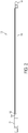
FIG. 1 is a perspective view of one aspect of an elongate dilator shaft for use with a dilator delivered nerve shield assembly; -
FIG. 2 is a side elevational view of the elongate dilator shaft ofFIG. 1 ; -
FIG. 3 is a perspective view of one aspect of an elongate nerve shield for use with a dilator delivered nerve shield assembly; -
FIG. 4 is a perspective view of the elongate nerve shield ofFIG. 3 , showing the elongate nerve shield's exterior surface; -
FIG. 5 is an end elevational view of the elongate nerve shield ofFIG. 3 ; -
FIG. 6 is a perspective view of one aspect of a dilator delivered nerve shield assembly; and -
FIG. 7 is a side elevational view of the dilator delivered nerve shield assembly ofFIG. 6 . - The present invention can be understood more readily by reference to the following detailed description, examples, and claims, and their previous and following description. Before the present system, devices, and/or methods are disclosed and described, it is to be understood that this invention is not limited to the specific systems, devices, and/or methods disclosed unless otherwise specified, as such can, of course, vary. It is also to be understood that the terminology used herein is for the purpose of describing particular aspects only and is not intended to be limiting.
- The following description of the invention is provided as an enabling teaching of the invention in its best, currently known aspect. Those skilled in the relevant art will recognize that many changes can be made to the aspects described, while still obtaining the beneficial results of the present invention. It will also be apparent that some of the desired benefits of the present invention can be obtained by selecting some of the features of the present invention without utilizing other features. Accordingly, those who work in the art will recognize that many modifications and adaptations to the present invention are possible and can even be desirable in certain circumstances and are a part of the present invention. Thus, the following description is provided as illustrative of the principles of the present invention and not in limitation thereof.
- As used herein, the singular forms "a," "an" and "the" include plural referents unless the context clearly dictates otherwise. Thus, for example, reference to a "shield" includes aspects having two or more shields unless the context clearly indicates otherwise.
- Ranges can be expressed herein as from "about" one particular value, and/or to "about" another particular value. When such a range is expressed, another aspect includes from the one particular value and/or to the other particular value. Similarly, when values are expressed as approximations, by use of the antecedent "about," it will be understood that the particular value forms another aspect. It will be further understood that the endpoints of each of the ranges are significant both in relation to the other endpoint, and independently of the other endpoint.
- As used herein, the terms "optional" or "optionally" mean that the subsequently described event or circumstance may or may not occur, and that the description includes instances where said event or circumstance occurs and instances where it does not.
- Terms used herein, such as "exemplary" or "exemplified," are not meant to show preference, but rather to explain that the aspect discussed thereafter is merely one example of the aspect presented.
- Presented herein is a dilator delivered
nerve shield assembly 10 for use in spinal surgery. In one aspect, the dilator deliverednerve shield assembly 10 comprises anelongate dilator shaft 100 with adistal end 110 and aproximal end 120. In one aspect, thedistal end 110 of the dilator elongate shaft is tapered to facilitate placing the elongate shaft percutaneously into the area of a desired motion segment. - The dilator delivered nerve shield assembly also comprises an
elongate nerve shield 200 that is configured for simultaneous insertion with theelongate dilator shaft 100. In one aspect, the elongate dilator shaft and theelongate nerve shield 200 engage one another to form the dilator delivered nerve shield assembly that is generally cylindrical in shape as a whole. It is contemplated that other shapes can also be utilized that may be substantially tubular with various cross sectional shapes, such as, but not limited round, elliptical, square, and the like. - The elongate nerve shield is an alternative to using a circumferential access portal / retractor for delivering an intervertebral interbody past the exiting nerve root. It achieves the result of shielding the exiting nerve root on one side of the implant path, without enlarging the path .
- In one aspect, the elongate dilator shaft has an
exterior surface 130 and at least oneengagement surface 140. In this aspect, the elongate nerve shield has aninterior surface 210 and anexterior surface 220 that is complimentary to theexterior surface 130 of theelongate dilator shaft 100 elongate surface, such that, when the elongate nerve shield is engaged with the elongate dilator shaft, the exterior surfaces of the combinedelongate dilator shaft 100 andelongate nerve shield 200 define theperipheral surface 15, forming the cross-sectional shape of the dilator deliverednerve shield assembly 10. For instance, if the dilator delivered nerve shield assembly has a circular cross-sectional shape, the engaged combined elongate dilator shaft and elongate nerve shield comprise the circular shape. - In another aspect, portions of the
engagement surface 140 of the elongate dilator shaft are complimentarily longitudinally keyed to portions of the interior surface of the elongate nerve shield. In this manner, when engaged, theelongate nerve shield 200 can slide longitudinally with respect to theelongate dilator shaft 100, but is retained from movement radially. In one aspect, the engagement surface of the elongate dilator shaft comprises at least onelongitudinal tongue 150. In this aspect, the interior surface of the elongate nerve shield defines at least onelongitudinal groove 230, where the groove and tongue are configured for a mating relationship. A plurality of tongues and complimentary grooves is also contemplated. In one aspect, where at least two grooves are present, the grooves can be angled with respect to one another to prevent radial movement of the elongate nerve shield with respect to the engaging surface. In yet another aspect, the elongate tongue can comprise a keyed relationship with the elongate groove. For example, and not meant to be limiting, the two can have a dovetail shaped cross-section or a keystone shaped cross-section and the like. Other interlocking geometries that permit longitudinal movement while preventing radial movement are also contemplated. It is also contemplated that the elongate nerve shield may comprise the tongues, while the elongate shaft's engagement surface defines the grooves. - In an exemplified aspect, the assembly comprises a
handle 20 connected to theproximal end 120 of the elongate dilator shaft. In one aspect, the handle and theelongate dilator shaft 100 are integral. As can be seen in the illustrations, the proximal end of the elongate dilator shaft can also comprise astop 160 to keep an engagedelongate nerve shield 200 from moving proximally in the longitudinal direction. - In use, the assembly can be positioned into the disc space between two adjacent vertebrae at the desired position and rotated to a point where the
exterior surface 220 of the elongate nerve shield is adjacent the nerve root. At this point, theelongate dilator shaft 100 may be removed, leaving the elongate nerve shield in position, shielding the nerve root from the operative field. Then, with the nerve root shielded, the surgeon can perform the necessary surgical procedure, such as, but not limited to, insertion of an inter-body cage without fear of damaging the nerve root. - In yet another aspect, the elongate dilator shaft can comprise an internal
longitudinal passageway 170. In this aspect, the system can be used to perform the surgical procedure over a guide wire. The proximal end of the handle of the system may also be sized and shaped to engage a rotation tool, such as a drill, or a larger handle. - In one aspect, the elongate dilator shaft can be conductive to allow for neurostimulation of the exiting nerve root. As can be appreciated the elongate dilator shaft may comprise stainless steel or aluminum and can be deanodized to be conductive. The elongate nerve shield can, in one aspect, comprise an insulating material. For example, and not meant to be limiting, the elongate nerve shield can comprise medical grade polymer.
- Although several aspects of the invention have been disclosed in the foregoing specification, it is understood by those skilled in the art that many modifications and other aspects of the invention will come to mind to which the invention pertains, having the benefit of the teaching presented in the foregoing description and associated drawings. It is thus understood that the invention is not limited to the specific aspects disclosed hereinabove, and that many modifications and other aspects are intended to be included within the scope of the appended claims. Moreover, although specific terms are employed herein, as well as in the claims that follow, they are used only in a generic and descriptive sense, and not for the purposes of limiting the described invention.
Claims (8)
- A dilator delivered nerve shield assembly (10) for spinal surgery comprising:
an elongate dilator shaft (100) having a distal end (110), a proximal end (120), an exterior surface (130), and at least one engagement surface (140); and an elongate nerve shield (200) having an interior surface (210) configured to engage at least a portion of the at least one engagement surface (140) and an exterior surface (220), wherein the exterior surface (220) of the elongate nerve shield (200) and the exterior surface (130) of the elongate dilator shaft (100) define a peripheral surface and form a cross-sectional tubular shape of the dilator delivered nerve shield assembly (10), characterized in that portions of the engagement surface of the elongate dilator shaft are complimentarily longitudinally keyed to portions of the interior surface of the elongate nerve shield, wherein when the elongate nerve shield is engaged with the elongate dilator shaft, the elongate nerve shield can slide longitudinally with respect to the elongate dilator shaft while being retained from substantially moving radially, the elongated dilator shaft being removable, leaving the elongate nerve shield in position, by sliding the dilator shaft longitudinally in a proximal direction with respect to the elongate shaft. - The dilator delivered nerve shield assembly of claim 1, wherein the peripheral surface forms a circular cross-sectional shape.
- The dilator delivered nerve shield assembly of claim 1, wherein the engagement surface of the elongate dilator shaft comprises at least one longitudinal tongue and the interior surface of the elongate nerve shield defines at least one longitudinal groove, and wherein the longitudinal tongue and the longitudinal groove are configured for a mating relationship.
- The dilator delivered nerve shield assembly of claim 1, further comprises a handle connected to the proximal end of the elongate dilator shaft.
- The dilator delivered nerve shield assembly of claim 4, wherein a proximal end of the handle is configured to engage a rotation tool.
- The dilator delivered nerve shield assembly of claim 1, wherein the elongate dilator shaft defines an internal longitudinal passageway configured for receipt of a guide wire.
- The dilator delivered nerve shield assembly of claim 1, wherein the elongate dilator shaft is substantially conductive to allow for neurostimulation of an exiting nerve root.
- The dilator delivered nerve shield assembly of claim 1, wherein the elongate nerve shield comprises an insulating material.
Applications Claiming Priority (3)
| Application Number | Priority Date | Filing Date | Title |
|---|---|---|---|
| US201261717579P | 2012-10-23 | 2012-10-23 | |
| US14/059,318 US9370348B2 (en) | 2012-10-23 | 2013-10-21 | Dilator delivered nerve shield |
| PCT/US2013/066077 WO2014066322A1 (en) | 2012-10-23 | 2013-10-22 | Dilator delivered nerve shield |
Publications (3)
| Publication Number | Publication Date |
|---|---|
| EP2911733A1 EP2911733A1 (en) | 2015-09-02 |
| EP2911733A4 EP2911733A4 (en) | 2016-07-13 |
| EP2911733B1 true EP2911733B1 (en) | 2019-07-31 |
Family
ID=50485932
Family Applications (1)
| Application Number | Title | Priority Date | Filing Date |
|---|---|---|---|
| EP13848470.4A Not-in-force EP2911733B1 (en) | 2012-10-23 | 2013-10-22 | Dilator delivered nerve shield |
Country Status (3)
| Country | Link |
|---|---|
| US (1) | US9370348B2 (en) |
| EP (1) | EP2911733B1 (en) |
| WO (1) | WO2014066322A1 (en) |
Families Citing this family (26)
| Publication number | Priority date | Publication date | Assignee | Title |
|---|---|---|---|---|
| US6907884B2 (en) | 2002-09-30 | 2005-06-21 | Depay Acromed, Inc. | Method of straddling an intraosseous nerve |
| US8361067B2 (en) | 2002-09-30 | 2013-01-29 | Relievant Medsystems, Inc. | Methods of therapeutically heating a vertebral body to treat back pain |
| US7258690B2 (en) | 2003-03-28 | 2007-08-21 | Relievant Medsystems, Inc. | Windowed thermal ablation probe |
| CA2737374C (en) | 2008-09-26 | 2017-03-28 | Relievant Medsystems, Inc. | Systems and methods for navigating an instrument through bone |
| US10028753B2 (en) | 2008-09-26 | 2018-07-24 | Relievant Medsystems, Inc. | Spine treatment kits |
| US10390877B2 (en) | 2011-12-30 | 2019-08-27 | Relievant Medsystems, Inc. | Systems and methods for treating back pain |
| US10588691B2 (en) | 2012-09-12 | 2020-03-17 | Relievant Medsystems, Inc. | Radiofrequency ablation of tissue within a vertebral body |
| IL238516B (en) | 2012-11-05 | 2022-08-01 | Relievant Medsystems Inc | System and methods for creating curved paths through bone and modulating nerves within the bone |
| US9724151B2 (en) | 2013-08-08 | 2017-08-08 | Relievant Medsystems, Inc. | Modulating nerves within bone using bone fasteners |
| US9662002B2 (en) * | 2014-07-10 | 2017-05-30 | Amendia, Inc. | Endoscopic portal protective shield assembly |
| US10136958B2 (en) * | 2014-10-28 | 2018-11-27 | Amendia, Inc. | Tissue protector and method of use |
| ES2870603T3 (en) | 2016-09-07 | 2021-10-27 | Vertos Medical Inc | Percutaneous lateral recess resection instruments |
| AU2019352954B2 (en) | 2018-10-01 | 2022-03-10 | I-Lumen Scientific, Inc. | System and methods for controlled electrical modulation for vision therapy |
| US11305118B2 (en) | 2018-11-30 | 2022-04-19 | Biovisics Medical, Inc. | Head worn apparatuses for vision therapy |
| US11471680B2 (en) | 2019-04-10 | 2022-10-18 | Biovisics, Inc. | Systems and interfaces for ocular therapy |
| ES2992491T3 (en) | 2019-06-14 | 2024-12-13 | I Lumen Scient Inc | Portable medical device |
| US12023498B2 (en) | 2019-07-12 | 2024-07-02 | Biovisics Medical, Inc. | Ocular therapy modes and systems |
| AU2020346827B2 (en) | 2019-09-12 | 2026-03-12 | Relievant Medsystems, Inc. | Systems and methods for tissue modulation |
| AU2021306313B2 (en) | 2020-07-10 | 2026-07-09 | Relievant Medsystems, Inc. | Vertebral denervation in conjunction with vertebral fusion |
| US12082876B1 (en) | 2020-09-28 | 2024-09-10 | Relievant Medsystems, Inc. | Introducer drill |
| AU2021409967A1 (en) | 2020-12-22 | 2023-08-03 | Relievant Medsystems, Inc. | Prediction of candidates for spinal neuromodulation |
| US12433668B1 (en) | 2021-11-08 | 2025-10-07 | Relievant Medsystems, Inc. | Impedance stoppage mitigation during radiofrequency tissue ablation procedures |
| PL4223241T3 (en) | 2022-02-07 | 2026-01-19 | Hoogland Spine Products Gmbh | DILATOR FOR SPINE SURGERY |
| US12465342B2 (en) | 2022-06-16 | 2025-11-11 | Vertos Medical, Inc. | Integrated instrument assembly |
| US12702831B2 (en) | 2022-09-29 | 2026-08-11 | I-Lumen Scientific, Inc. | Systems and methods to manage microcurrent therapy dose |
| US12589243B2 (en) | 2022-10-21 | 2026-03-31 | I-Lumen Scientific, Inc. | Ocular devices and controller interfaces for ocular therapy |
Family Cites Families (19)
| Publication number | Priority date | Publication date | Assignee | Title |
|---|---|---|---|---|
| US5759150A (en) | 1995-07-07 | 1998-06-02 | Olympus Optical Co., Ltd. | System for evulsing subcutaneous tissue |
| US7485092B1 (en) | 1998-08-12 | 2009-02-03 | Maquet Cardiovascular Llc | Vessel harvesting apparatus and method |
| US6896680B2 (en) | 2001-03-01 | 2005-05-24 | Gary K. Michelson | Arcuate dynamic lordotic guard with movable extensions for creating an implantation space posteriorly in the lumbar spine |
| US6999819B2 (en) * | 2001-08-31 | 2006-02-14 | Medtronic, Inc. | Implantable medical electrical stimulation lead fixation method and apparatus |
| EP2481338A3 (en) | 2001-09-25 | 2012-09-05 | Nuvasive, Inc. | System for performing surgical procedures and assessments |
| US7226451B2 (en) * | 2003-08-26 | 2007-06-05 | Shluzas Alan E | Minimally invasive access device and method |
| WO2005018466A2 (en) * | 2003-08-26 | 2005-03-03 | Endius, Inc. | Access systems and methods for minimally invasive surgery |
| CA2802131C (en) * | 2004-02-10 | 2015-10-06 | Spinal Elements, Inc. | System and method for protecting neurovascular structures |
| US7578819B2 (en) | 2005-05-16 | 2009-08-25 | Baxano, Inc. | Spinal access and neural localization |
| US20060217754A1 (en) | 2005-03-23 | 2006-09-28 | Boehm Frank H Jr | Expandable intervertebral disc dilating cannula |
| WO2009046414A1 (en) | 2007-10-05 | 2009-04-09 | Synthes (U.S.A.) | Dilation system and method of using the same |
| US7951110B2 (en) | 2008-11-10 | 2011-05-31 | Onset Medical Corporation | Expandable spinal sheath and method of use |
| US8187231B2 (en) * | 2009-06-26 | 2012-05-29 | Tyco Healthcare Group Lp | Catheterization system |
| US9173705B2 (en) | 2010-05-13 | 2015-11-03 | Ncontact Surgical, Inc. | Subxyphoid epicardial ablation |
| US8617062B2 (en) * | 2010-07-08 | 2013-12-31 | Warsaw Orthopedic, Inc. | Over dilation |
| US20120022575A1 (en) * | 2010-07-26 | 2012-01-26 | Warsaw Orthopedic, Inc. An Indiana Corporation | Laterally expanding surgical dilator |
| US8702600B2 (en) * | 2011-03-08 | 2014-04-22 | Pioneer Surgical Technology, Inc. | Apparatus and method for enlarging an incision |
| US8518087B2 (en) * | 2011-03-10 | 2013-08-27 | Interventional Spine, Inc. | Method and apparatus for minimally invasive insertion of intervertebral implants |
| US8394129B2 (en) * | 2011-03-10 | 2013-03-12 | Interventional Spine, Inc. | Method and apparatus for minimally invasive insertion of intervertebral implants |
-
2013
- 2013-10-21 US US14/059,318 patent/US9370348B2/en not_active Expired - Fee Related
- 2013-10-22 WO PCT/US2013/066077 patent/WO2014066322A1/en not_active Ceased
- 2013-10-22 EP EP13848470.4A patent/EP2911733B1/en not_active Not-in-force
Non-Patent Citations (1)
| Title |
|---|
| None * |
Also Published As
| Publication number | Publication date |
|---|---|
| EP2911733A1 (en) | 2015-09-02 |
| US20140114133A1 (en) | 2014-04-24 |
| EP2911733A4 (en) | 2016-07-13 |
| WO2014066322A1 (en) | 2014-05-01 |
| US9370348B2 (en) | 2016-06-21 |
Similar Documents
| Publication | Publication Date | Title |
|---|---|---|
| US9370348B2 (en) | Dilator delivered nerve shield | |
| Ahn et al. | Percutaneous endoscopic lumbar foraminotomy: an advanced surgical technique and clinical outcomes | |
| US9241722B2 (en) | Surgical pin guide and methods of use | |
| US8834507B2 (en) | Dilation instruments and methods | |
| US9675303B2 (en) | Visualization systems, instruments and methods of using the same in spinal decompression procedures | |
| US9055936B2 (en) | Over dilation | |
| US20070066977A1 (en) | Exchange system for axial spinal procedures | |
| Hwang et al. | Contralateral interlaminar keyhole percutaneous endoscopic lumbar surgery in patients with unilateral radiculopathy | |
| US12207826B2 (en) | Combined bone tap and rasp | |
| EP3139848A1 (en) | Spinal nerve decompression systems, dilation systems, and methods of using the same | |
| AU2012256311A1 (en) | Dilation instruments and methods | |
| US10639057B2 (en) | Multi-tine cutting device | |
| JP7546928B2 (en) | Medical Delivery Devices | |
| Li et al. | Percutaneous isthmus foraminoplasty and full-endoscopic lumbar discectomy for very highly upmigrated lumbar disc herniation: technique notes and 2 years follow-up | |
| Telfeian | Transforaminal endoscopic solution to disk reherniation post-mini-TLIF: case report | |
| Yao et al. | Percutaneous endoscopic transforaminal decompression in the treatment of patients with migrated lumbar disc herniation: a retrospective study | |
| WO2016191201A1 (en) | Interspinous process implant having a body with a removable end portion | |
| US20170020404A1 (en) | Neuromonitoring probe systems and methods | |
| Hsu et al. | Full-endoscopic interlaminar discectomy for herniation at L3–4 and L4–5 | |
| Bhanot | 2 Injection Techniques in Spine | |
| Bhanot | in Spine Injection Techniques in Spine |
Legal Events
| Date | Code | Title | Description |
|---|---|---|---|
| PUAI | Public reference made under article 153(3) epc to a published international application that has entered the european phase |
Free format text: ORIGINAL CODE: 0009012 |
|
| 17P | Request for examination filed |
Effective date: 20150521 |
|
| AK | Designated contracting states |
Kind code of ref document: A1 Designated state(s): AL AT BE BG CH CY CZ DE DK EE ES FI FR GB GR HR HU IE IS IT LI LT LU LV MC MK MT NL NO PL PT RO RS SE SI SK SM TR |
|
| AX | Request for extension of the european patent |
Extension state: BA ME |
|
| DAX | Request for extension of the european patent (deleted) | ||
| RIN1 | Information on inventor provided before grant (corrected) |
Inventor name: BARRA, KENNETH Inventor name: TALLY, WILLIAM |
|
| RA4 | Supplementary search report drawn up and despatched (corrected) |
Effective date: 20160610 |
|
| RIC1 | Information provided on ipc code assigned before grant |
Ipc: A61M 29/00 20060101AFI20160606BHEP Ipc: A61B 17/00 20060101ALI20160606BHEP Ipc: A61B 17/34 20060101ALI20160606BHEP |
|
| GRAP | Despatch of communication of intention to grant a patent |
Free format text: ORIGINAL CODE: EPIDOSNIGR1 |
|
| STAA | Information on the status of an ep patent application or granted ep patent |
Free format text: STATUS: GRANT OF PATENT IS INTENDED |
|
| RIC1 | Information provided on ipc code assigned before grant |
Ipc: A61B 17/88 20060101ALI20181120BHEP Ipc: A61B 17/00 20060101ALI20181120BHEP Ipc: A61M 29/00 20060101AFI20181120BHEP Ipc: A61B 17/34 20060101ALI20181120BHEP Ipc: A61B 17/16 20060101ALI20181120BHEP |
|
| INTG | Intention to grant announced |
Effective date: 20181218 |
|
| GRAJ | Information related to disapproval of communication of intention to grant by the applicant or resumption of examination proceedings by the epo deleted |
Free format text: ORIGINAL CODE: EPIDOSDIGR1 |
|
| STAA | Information on the status of an ep patent application or granted ep patent |
Free format text: STATUS: REQUEST FOR EXAMINATION WAS MADE |
|
| INTC | Intention to grant announced (deleted) | ||
| GRAR | Information related to intention to grant a patent recorded |
Free format text: ORIGINAL CODE: EPIDOSNIGR71 |
|
| GRAS | Grant fee paid |
Free format text: ORIGINAL CODE: EPIDOSNIGR3 |
|
| STAA | Information on the status of an ep patent application or granted ep patent |
Free format text: STATUS: GRANT OF PATENT IS INTENDED |
|
| GRAA | (expected) grant |
Free format text: ORIGINAL CODE: 0009210 |
|
| STAA | Information on the status of an ep patent application or granted ep patent |
Free format text: STATUS: THE PATENT HAS BEEN GRANTED |
|
| AK | Designated contracting states |
Kind code of ref document: B1 Designated state(s): AL AT BE BG CH CY CZ DE DK EE ES FI FR GB GR HR HU IE IS IT LI LT LU LV MC MK MT NL NO PL PT RO RS SE SI SK SM TR |
|
| INTG | Intention to grant announced |
Effective date: 20190621 |
|
| REG | Reference to a national code |
Ref country code: CH Ref legal event code: EP Ref country code: GB Ref legal event code: FG4D |
|
| REG | Reference to a national code |
Ref country code: DE Ref legal event code: R096 Ref document number: 602013058603 Country of ref document: DE |
|
| REG | Reference to a national code |
Ref country code: AT Ref legal event code: REF Ref document number: 1160287 Country of ref document: AT Kind code of ref document: T Effective date: 20190815 |
|
| REG | Reference to a national code |
Ref country code: IE Ref legal event code: FG4D |
|
| REG | Reference to a national code |
Ref country code: NL Ref legal event code: MP Effective date: 20190731 |
|
| REG | Reference to a national code |
Ref country code: LT Ref legal event code: MG4D |
|
| REG | Reference to a national code |
Ref country code: AT Ref legal event code: MK05 Ref document number: 1160287 Country of ref document: AT Kind code of ref document: T Effective date: 20190731 |
|
| PG25 | Lapsed in a contracting state [announced via postgrant information from national office to epo] |
Ref country code: PT Free format text: LAPSE BECAUSE OF FAILURE TO SUBMIT A TRANSLATION OF THE DESCRIPTION OR TO PAY THE FEE WITHIN THE PRESCRIBED TIME-LIMIT Effective date: 20191202 Ref country code: SE Free format text: LAPSE BECAUSE OF FAILURE TO SUBMIT A TRANSLATION OF THE DESCRIPTION OR TO PAY THE FEE WITHIN THE PRESCRIBED TIME-LIMIT Effective date: 20190731 Ref country code: NO Free format text: LAPSE BECAUSE OF FAILURE TO SUBMIT A TRANSLATION OF THE DESCRIPTION OR TO PAY THE FEE WITHIN THE PRESCRIBED TIME-LIMIT Effective date: 20191031 Ref country code: AT Free format text: LAPSE BECAUSE OF FAILURE TO SUBMIT A TRANSLATION OF THE DESCRIPTION OR TO PAY THE FEE WITHIN THE PRESCRIBED TIME-LIMIT Effective date: 20190731 Ref country code: FI Free format text: LAPSE BECAUSE OF FAILURE TO SUBMIT A TRANSLATION OF THE DESCRIPTION OR TO PAY THE FEE WITHIN THE PRESCRIBED TIME-LIMIT Effective date: 20190731 Ref country code: LT Free format text: LAPSE BECAUSE OF FAILURE TO SUBMIT A TRANSLATION OF THE DESCRIPTION OR TO PAY THE FEE WITHIN THE PRESCRIBED TIME-LIMIT Effective date: 20190731 Ref country code: HR Free format text: LAPSE BECAUSE OF FAILURE TO SUBMIT A TRANSLATION OF THE DESCRIPTION OR TO PAY THE FEE WITHIN THE PRESCRIBED TIME-LIMIT Effective date: 20190731 Ref country code: BG Free format text: LAPSE BECAUSE OF FAILURE TO SUBMIT A TRANSLATION OF THE DESCRIPTION OR TO PAY THE FEE WITHIN THE PRESCRIBED TIME-LIMIT Effective date: 20191031 Ref country code: NL Free format text: LAPSE BECAUSE OF FAILURE TO SUBMIT A TRANSLATION OF THE DESCRIPTION OR TO PAY THE FEE WITHIN THE PRESCRIBED TIME-LIMIT Effective date: 20190731 |
|
| PG25 | Lapsed in a contracting state [announced via postgrant information from national office to epo] |
Ref country code: GR Free format text: LAPSE BECAUSE OF FAILURE TO SUBMIT A TRANSLATION OF THE DESCRIPTION OR TO PAY THE FEE WITHIN THE PRESCRIBED TIME-LIMIT Effective date: 20191101 Ref country code: LV Free format text: LAPSE BECAUSE OF FAILURE TO SUBMIT A TRANSLATION OF THE DESCRIPTION OR TO PAY THE FEE WITHIN THE PRESCRIBED TIME-LIMIT Effective date: 20190731 Ref country code: IS Free format text: LAPSE BECAUSE OF FAILURE TO SUBMIT A TRANSLATION OF THE DESCRIPTION OR TO PAY THE FEE WITHIN THE PRESCRIBED TIME-LIMIT Effective date: 20191130 Ref country code: AL Free format text: LAPSE BECAUSE OF FAILURE TO SUBMIT A TRANSLATION OF THE DESCRIPTION OR TO PAY THE FEE WITHIN THE PRESCRIBED TIME-LIMIT Effective date: 20190731 Ref country code: RS Free format text: LAPSE BECAUSE OF FAILURE TO SUBMIT A TRANSLATION OF THE DESCRIPTION OR TO PAY THE FEE WITHIN THE PRESCRIBED TIME-LIMIT Effective date: 20190731 Ref country code: ES Free format text: LAPSE BECAUSE OF FAILURE TO SUBMIT A TRANSLATION OF THE DESCRIPTION OR TO PAY THE FEE WITHIN THE PRESCRIBED TIME-LIMIT Effective date: 20190731 |
|
| PG25 | Lapsed in a contracting state [announced via postgrant information from national office to epo] |
Ref country code: TR Free format text: LAPSE BECAUSE OF FAILURE TO SUBMIT A TRANSLATION OF THE DESCRIPTION OR TO PAY THE FEE WITHIN THE PRESCRIBED TIME-LIMIT Effective date: 20190731 |
|
| PG25 | Lapsed in a contracting state [announced via postgrant information from national office to epo] |
Ref country code: IT Free format text: LAPSE BECAUSE OF FAILURE TO SUBMIT A TRANSLATION OF THE DESCRIPTION OR TO PAY THE FEE WITHIN THE PRESCRIBED TIME-LIMIT Effective date: 20190731 Ref country code: RO Free format text: LAPSE BECAUSE OF FAILURE TO SUBMIT A TRANSLATION OF THE DESCRIPTION OR TO PAY THE FEE WITHIN THE PRESCRIBED TIME-LIMIT Effective date: 20190731 Ref country code: DK Free format text: LAPSE BECAUSE OF FAILURE TO SUBMIT A TRANSLATION OF THE DESCRIPTION OR TO PAY THE FEE WITHIN THE PRESCRIBED TIME-LIMIT Effective date: 20190731 Ref country code: PL Free format text: LAPSE BECAUSE OF FAILURE TO SUBMIT A TRANSLATION OF THE DESCRIPTION OR TO PAY THE FEE WITHIN THE PRESCRIBED TIME-LIMIT Effective date: 20190731 Ref country code: EE Free format text: LAPSE BECAUSE OF FAILURE TO SUBMIT A TRANSLATION OF THE DESCRIPTION OR TO PAY THE FEE WITHIN THE PRESCRIBED TIME-LIMIT Effective date: 20190731 |
|
| PG25 | Lapsed in a contracting state [announced via postgrant information from national office to epo] |
Ref country code: IS Free format text: LAPSE BECAUSE OF FAILURE TO SUBMIT A TRANSLATION OF THE DESCRIPTION OR TO PAY THE FEE WITHIN THE PRESCRIBED TIME-LIMIT Effective date: 20200224 Ref country code: CZ Free format text: LAPSE BECAUSE OF FAILURE TO SUBMIT A TRANSLATION OF THE DESCRIPTION OR TO PAY THE FEE WITHIN THE PRESCRIBED TIME-LIMIT Effective date: 20190731 Ref country code: SM Free format text: LAPSE BECAUSE OF FAILURE TO SUBMIT A TRANSLATION OF THE DESCRIPTION OR TO PAY THE FEE WITHIN THE PRESCRIBED TIME-LIMIT Effective date: 20190731 Ref country code: MC Free format text: LAPSE BECAUSE OF FAILURE TO SUBMIT A TRANSLATION OF THE DESCRIPTION OR TO PAY THE FEE WITHIN THE PRESCRIBED TIME-LIMIT Effective date: 20190731 Ref country code: SK Free format text: LAPSE BECAUSE OF FAILURE TO SUBMIT A TRANSLATION OF THE DESCRIPTION OR TO PAY THE FEE WITHIN THE PRESCRIBED TIME-LIMIT Effective date: 20190731 |
|
| REG | Reference to a national code |
Ref country code: CH Ref legal event code: PL |
|
| REG | Reference to a national code |
Ref country code: DE Ref legal event code: R097 Ref document number: 602013058603 Country of ref document: DE |
|
| PLBE | No opposition filed within time limit |
Free format text: ORIGINAL CODE: 0009261 |
|
| STAA | Information on the status of an ep patent application or granted ep patent |
Free format text: STATUS: NO OPPOSITION FILED WITHIN TIME LIMIT |
|
| PG2D | Information on lapse in contracting state deleted |
Ref country code: IS |
|
| PG25 | Lapsed in a contracting state [announced via postgrant information from national office to epo] |
Ref country code: LU Free format text: LAPSE BECAUSE OF NON-PAYMENT OF DUE FEES Effective date: 20191022 Ref country code: CH Free format text: LAPSE BECAUSE OF NON-PAYMENT OF DUE FEES Effective date: 20191031 Ref country code: LI Free format text: LAPSE BECAUSE OF NON-PAYMENT OF DUE FEES Effective date: 20191031 Ref country code: IS Free format text: LAPSE BECAUSE OF FAILURE TO SUBMIT A TRANSLATION OF THE DESCRIPTION OR TO PAY THE FEE WITHIN THE PRESCRIBED TIME-LIMIT Effective date: 20191030 |
|
| 26N | No opposition filed |
Effective date: 20200603 |
|
| REG | Reference to a national code |
Ref country code: BE Ref legal event code: MM Effective date: 20191031 |
|
| PG25 | Lapsed in a contracting state [announced via postgrant information from national office to epo] |
Ref country code: BE Free format text: LAPSE BECAUSE OF NON-PAYMENT OF DUE FEES Effective date: 20191031 Ref country code: SI Free format text: LAPSE BECAUSE OF FAILURE TO SUBMIT A TRANSLATION OF THE DESCRIPTION OR TO PAY THE FEE WITHIN THE PRESCRIBED TIME-LIMIT Effective date: 20190731 |
|
| PG25 | Lapsed in a contracting state [announced via postgrant information from national office to epo] |
Ref country code: IE Free format text: LAPSE BECAUSE OF NON-PAYMENT OF DUE FEES Effective date: 20191022 |
|
| PG25 | Lapsed in a contracting state [announced via postgrant information from national office to epo] |
Ref country code: CY Free format text: LAPSE BECAUSE OF FAILURE TO SUBMIT A TRANSLATION OF THE DESCRIPTION OR TO PAY THE FEE WITHIN THE PRESCRIBED TIME-LIMIT Effective date: 20190731 |
|
| PG25 | Lapsed in a contracting state [announced via postgrant information from national office to epo] |
Ref country code: MT Free format text: LAPSE BECAUSE OF FAILURE TO SUBMIT A TRANSLATION OF THE DESCRIPTION OR TO PAY THE FEE WITHIN THE PRESCRIBED TIME-LIMIT Effective date: 20190731 Ref country code: HU Free format text: LAPSE BECAUSE OF FAILURE TO SUBMIT A TRANSLATION OF THE DESCRIPTION OR TO PAY THE FEE WITHIN THE PRESCRIBED TIME-LIMIT; INVALID AB INITIO Effective date: 20131022 |
|
| PG25 | Lapsed in a contracting state [announced via postgrant information from national office to epo] |
Ref country code: MK Free format text: LAPSE BECAUSE OF FAILURE TO SUBMIT A TRANSLATION OF THE DESCRIPTION OR TO PAY THE FEE WITHIN THE PRESCRIBED TIME-LIMIT Effective date: 20190731 |
|
| PGFP | Annual fee paid to national office [announced via postgrant information from national office to epo] |
Ref country code: GB Payment date: 20220901 Year of fee payment: 10 |
|
| PGFP | Annual fee paid to national office [announced via postgrant information from national office to epo] |
Ref country code: FR Payment date: 20220908 Year of fee payment: 10 |
|
| PGFP | Annual fee paid to national office [announced via postgrant information from national office to epo] |
Ref country code: DE Payment date: 20220831 Year of fee payment: 10 |
|
| REG | Reference to a national code |
Ref country code: DE Ref legal event code: R119 Ref document number: 602013058603 Country of ref document: DE |
|
| GBPC | Gb: european patent ceased through non-payment of renewal fee |
Effective date: 20231022 |
|
| PG25 | Lapsed in a contracting state [announced via postgrant information from national office to epo] |
Ref country code: GB Free format text: LAPSE BECAUSE OF NON-PAYMENT OF DUE FEES Effective date: 20231022 |
|
| PG25 | Lapsed in a contracting state [announced via postgrant information from national office to epo] |
Ref country code: GB Free format text: LAPSE BECAUSE OF NON-PAYMENT OF DUE FEES Effective date: 20231022 Ref country code: FR Free format text: LAPSE BECAUSE OF NON-PAYMENT OF DUE FEES Effective date: 20231031 Ref country code: DE Free format text: LAPSE BECAUSE OF NON-PAYMENT OF DUE FEES Effective date: 20240501 |