EP2911285A1 - Interleaved llc current equalizing converter - Google Patents
Interleaved llc current equalizing converter Download PDFInfo
- Publication number
- EP2911285A1 EP2911285A1 EP13849068.5A EP13849068A EP2911285A1 EP 2911285 A1 EP2911285 A1 EP 2911285A1 EP 13849068 A EP13849068 A EP 13849068A EP 2911285 A1 EP2911285 A1 EP 2911285A1
- Authority
- EP
- European Patent Office
- Prior art keywords
- llc
- windings
- interleaved
- convertor
- current sharing
- Prior art date
- Legal status (The legal status is an assumption and is not a legal conclusion. Google has not performed a legal analysis and makes no representation as to the accuracy of the status listed.)
- Withdrawn
Links
- 238000004804 winding Methods 0.000 claims abstract description 55
- 230000010287 polarization Effects 0.000 claims abstract description 7
- 239000003990 capacitor Substances 0.000 claims description 19
- 238000010586 diagram Methods 0.000 description 8
- 230000006872 improvement Effects 0.000 description 8
- 230000000694 effects Effects 0.000 description 4
- 230000008878 coupling Effects 0.000 description 3
- 238000010168 coupling process Methods 0.000 description 3
- 238000005859 coupling reaction Methods 0.000 description 3
- 230000010354 integration Effects 0.000 description 2
- 238000004088 simulation Methods 0.000 description 2
- 230000002301 combined effect Effects 0.000 description 1
- 238000004519 manufacturing process Methods 0.000 description 1
- 238000000034 method Methods 0.000 description 1
- 230000004048 modification Effects 0.000 description 1
- 238000012986 modification Methods 0.000 description 1
- 230000006855 networking Effects 0.000 description 1
Images




Classifications
-
- H—ELECTRICITY
- H02—GENERATION; CONVERSION OR DISTRIBUTION OF ELECTRIC POWER
- H02M—APPARATUS FOR CONVERSION BETWEEN AC AND AC, BETWEEN AC AND DC, OR BETWEEN DC AND DC, AND FOR USE WITH MAINS OR SIMILAR POWER SUPPLY SYSTEMS; CONVERSION OF DC OR AC INPUT POWER INTO SURGE OUTPUT POWER; CONTROL OR REGULATION THEREOF
- H02M3/00—Conversion of DC power input into DC power output
- H02M3/22—Conversion of DC power input into DC power output with intermediate conversion into AC
- H02M3/24—Conversion of DC power input into DC power output with intermediate conversion into AC by static converters
- H02M3/28—Conversion of DC power input into DC power output with intermediate conversion into AC by static converters using discharge tubes with control electrode or semiconductor devices with control electrode to produce the intermediate AC
- H02M3/325—Conversion of DC power input into DC power output with intermediate conversion into AC by static converters using discharge tubes with control electrode or semiconductor devices with control electrode to produce the intermediate AC using devices of a triode or a transistor type requiring continuous application of a control signal
- H02M3/335—Conversion of DC power input into DC power output with intermediate conversion into AC by static converters using discharge tubes with control electrode or semiconductor devices with control electrode to produce the intermediate AC using devices of a triode or a transistor type requiring continuous application of a control signal using semiconductor devices only
- H02M3/33507—Conversion of DC power input into DC power output with intermediate conversion into AC by static converters using discharge tubes with control electrode or semiconductor devices with control electrode to produce the intermediate AC using devices of a triode or a transistor type requiring continuous application of a control signal using semiconductor devices only with automatic control of the output voltage or current, e.g. flyback converters
-
- H—ELECTRICITY
- H02—GENERATION; CONVERSION OR DISTRIBUTION OF ELECTRIC POWER
- H02M—APPARATUS FOR CONVERSION BETWEEN AC AND AC, BETWEEN AC AND DC, OR BETWEEN DC AND DC, AND FOR USE WITH MAINS OR SIMILAR POWER SUPPLY SYSTEMS; CONVERSION OF DC OR AC INPUT POWER INTO SURGE OUTPUT POWER; CONTROL OR REGULATION THEREOF
- H02M1/00—Details of apparatus for conversion
- H02M1/14—Arrangements for reducing ripples from DC input or output
-
- H—ELECTRICITY
- H02—GENERATION; CONVERSION OR DISTRIBUTION OF ELECTRIC POWER
- H02M—APPARATUS FOR CONVERSION BETWEEN AC AND AC, BETWEEN AC AND DC, OR BETWEEN DC AND DC, AND FOR USE WITH MAINS OR SIMILAR POWER SUPPLY SYSTEMS; CONVERSION OF DC OR AC INPUT POWER INTO SURGE OUTPUT POWER; CONTROL OR REGULATION THEREOF
- H02M3/00—Conversion of DC power input into DC power output
- H02M3/22—Conversion of DC power input into DC power output with intermediate conversion into AC
- H02M3/24—Conversion of DC power input into DC power output with intermediate conversion into AC by static converters
- H02M3/28—Conversion of DC power input into DC power output with intermediate conversion into AC by static converters using discharge tubes with control electrode or semiconductor devices with control electrode to produce the intermediate AC
- H02M3/285—Single converters with a plurality of output stages connected in parallel
-
- H—ELECTRICITY
- H02—GENERATION; CONVERSION OR DISTRIBUTION OF ELECTRIC POWER
- H02M—APPARATUS FOR CONVERSION BETWEEN AC AND AC, BETWEEN AC AND DC, OR BETWEEN DC AND DC, AND FOR USE WITH MAINS OR SIMILAR POWER SUPPLY SYSTEMS; CONVERSION OF DC OR AC INPUT POWER INTO SURGE OUTPUT POWER; CONTROL OR REGULATION THEREOF
- H02M1/00—Details of apparatus for conversion
- H02M1/0003—Details of control, feedback or regulation circuits
-
- H—ELECTRICITY
- H02—GENERATION; CONVERSION OR DISTRIBUTION OF ELECTRIC POWER
- H02M—APPARATUS FOR CONVERSION BETWEEN AC AND AC, BETWEEN AC AND DC, OR BETWEEN DC AND DC, AND FOR USE WITH MAINS OR SIMILAR POWER SUPPLY SYSTEMS; CONVERSION OF DC OR AC INPUT POWER INTO SURGE OUTPUT POWER; CONTROL OR REGULATION THEREOF
- H02M1/00—Details of apparatus for conversion
- H02M1/0048—Circuits or arrangements for reducing losses
- H02M1/0054—Transistor switching losses
- H02M1/0058—Transistor switching losses by employing soft switching techniques, i.e. commutation of transistors when applied voltage is zero or when current flow is zero
-
- Y—GENERAL TAGGING OF NEW TECHNOLOGICAL DEVELOPMENTS; GENERAL TAGGING OF CROSS-SECTIONAL TECHNOLOGIES SPANNING OVER SEVERAL SECTIONS OF THE IPC; TECHNICAL SUBJECTS COVERED BY FORMER USPC CROSS-REFERENCE ART COLLECTIONS [XRACs] AND DIGESTS
- Y02—TECHNOLOGIES OR APPLICATIONS FOR MITIGATION OR ADAPTATION AGAINST CLIMATE CHANGE
- Y02B—CLIMATE CHANGE MITIGATION TECHNOLOGIES RELATED TO BUILDINGS, e.g. HOUSING, HOUSE APPLIANCES OR RELATED END-USER APPLICATIONS
- Y02B70/00—Technologies for an efficient end-user side electric power management and consumption
- Y02B70/10—Technologies improving the efficiency by using switched-mode power supplies [SMPS], i.e. efficient power electronics conversion e.g. power factor correction or reduction of losses in power supplies or efficient standby modes
Definitions
- the present invention generally relates to an LLC convertor, and more particularly, to an interleaved LLC convertor with current sharing.
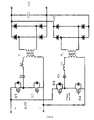
- LLC topology (as shown in FIG.1 ) is widely used in various kinds of products, such as LCD TV, networking power supply etc. LLC has at least following advantages: a) achieving ZVS for switching transistors without extra circuits, meeting the requirement of high frequency and high efficiency at the same time; b) ZCS for secondary rectification at the secondary side and low voltage stress, which contribute to high efficiency, therefore being very suitable for two stage topology with PFC as its first stage to improve the efficiency of AC input and DC output; c) no output inductance and low cost; and d) easy for magnetic integration in the applications lower than 500W.
- LLC topology is widely used due to the above advantages.
- LLC has no output filter inductance, which means, in order to solve the problem of large current ripple, a lot of capacitors connected in parallel in the output terminal are required to absorb the current ripple, especially in the low output voltage/high current/high power applications.
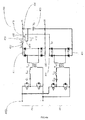
- interleaved LLC topology (as shown in FIG.2 ) can solve the current ripple problem significantly, and reduce the stress on the capacitors, which makes interleaved LLC a better solution in high power or high current level applications.
- two LLC convertors operate in parallel under the condition that there is 90° phase difference between the drivers. The parameters of the two resonant cavities may not be completely consistent with each other in practical application.
- the present invention intends to overcome the current sharing issue of the interleaved LLC and use it in high power, high current and high frequency applications.
- An interleaved LLC convertor with current sharing is provided in the present invention to solve this technical problem.
- the interleaved LLC convertor with current sharing comprises: an interleaved LLC circuit, consisting of an even number of LLC circuits connected in parallel; and a plurality of windings with the same quantity as that of the LLC circuits.
- all first polarization terminals of each of LLC circuits at its DC output side together constitute a first output terminal; all first terminals of each of the windings together constitute a second output terminal; a first half of the plurality of windings surround a magnetic core in a first direction, and a second half of the plurality of windings surround the magnetic core in a second direction; each of the plurality of windings has the same inductance, and the first half of the plurality of windings are inversely coupled with the second half of the plurality of windings; and the second polarization terminal of each LLC circuit at its DC output side connects to a second terminal of one of the windings.
- the interleaved LLC convertor with current sharing further comprises an output capacitor connected between the first output terminal and the second output terminal.
- said output capacitor is an electrolytic capacitor.
- the magnetic core in said interleaved LLC convertor with current sharing is closed magnetic core.
- the interleaved LLC circuit in the interleaved LLC convertor with current sharing consists of two LLC circuits connected in parallel.
- the inductance of the winding in said interleaved LLC convertor with current sharing is no more than L r /n 2 , wherein n is the turn ratio of transformer of the LLC circuit, L r is the inductance of the resonant inductor in the LLC circuit if the plurality of windings are not included in the interleaved LLC convertor with current sharing.
- the inductance of said winding is no more than L r /(2 ⁇ n 2 )
- the tolerance of the resonant parameters (resonant inductance L r , resonant capacitance C r ) of the LLC circuit in said interleaved LLC convertor with current sharing is no more than 10%.
- the interleaved LLC convertor with current sharing 400 comprises an interleaved LLC circuit which consists of two LLC circuits 401 connected in parallel, and a coupled inductor 402.
- the LLC circuits 401 could be of any commercially available LLC topology.
- the coupled inductor 402 consists of two windings 403 and a magnetic core 404, positioned between the output diode 405 of the LLC circuit 401 and the output capacitor 406 of the LLC convertor with current sharing 400.
- the magnetic core 404 may be opened magnetic core or closed magnetic core.
- the magnetic core is a closed magnetic core.
- the closed magnetic core By using the closed magnetic core, there is less interference to the surrounding components, and it is easier to fabricate the inductors with a plurality of windings.
- the positive terminals 407 of the two LLC circuits at their DC output sides together constitute a first output terminal 408; and the first terminals 409 of the two windings 403 together constitute a second terminal 410.
- one of the two windings surround the magnetic core 404 in a first direction, while the other one of the two windings surround the magnetic core 404 in a second direction.
- Each of the two windings has the same inductance, and inversely coupled with each other on the magnetic core 404.
- each of the two LLC circuits 401 at its DC output side connects to second terminals 412 (i.e. the terminals not constituting the second output terminal 410 with the other winding 403) of the two windings 403 respectively.
- Said output capacitor 406 is connected between the first output terminal 408 and the second output terminal 410; the output capacitor 406 is a common capacitor which is available in the market, such as film capacitor or electrolytic capacitor.
- FIG.4a can be taken as the resonant inductances L r of T1&T2 in a simple interleaved LLC circuit (see FIG.2 ) being split respectively into L r 1 &L 1 and L r2 & L 2 , wherein L r 1 &L r 2 are positioned in the resonant cavity and involved in resonance, and the inductance of them is ⁇ L r ( ⁇ is the coefficient of the inductance shared by resonant inductance at the primary side); each of L 1 &L 2 is respectively the inductance generated on the magnetic core 404 by the two windings 403 coupled with each other and positioned after the output diodes 405, and each of the inductances is (1- ⁇ ) ⁇ L r / n 2 , wherein n is the turn ratio of transformer.
- the interleaved LLC would make use of the portion of the coupled inductor 402 in the secondary side so that, when the current of the LLC circuits 401 is unbalance, different mutual inductance will be generated on the coupled inductor 402 due to the effect of current and can be added to the primary side and involved in the resonance during operation, thus achieving the current sharing.
- ⁇ should be above zero, or the LLC circuit would no longer exist since there is no inductance at the primary side at all.
- each of the inductances at the secondary side L 1 &L 2 is less than L r /n 2 according to an embodiment of the present invention.
- each of the inductances at the secondary side L 1 & L 2 is no more than L r /(2 ⁇ n2).
- the operating frequency of each of the LLC circuits 401 in the interleaved LLC convertor with current sharing 400 may be different. However, the operating frequencies of the LLC circuits 401 in the interleaved LLC convertor with current sharing 400 are equal according to a preferred embodiment of the present invention. According to this embodiment, because the operating frequencies of the LLC circuits 401 are equal, we can use a controller (not shown in FIG.4a ) to control all the LLC circuits 401 which constitute the interleaved LLC circuit 400. Compared with the device with different operating frequencies, the device with such control method is easier to be controlled with lower manufacture cost.
- the difference of the phase angles of the LLC circuits 401 in the interleaved LLC convertor with current sharing 400 is 180/N degree, when the LLC circuits 401 operate in parallel, according to a preferred embodiment of the present invention, wherein N is the quantity of the LLC circuits 401.
- the difference of the phase angles is 180/N degree, the output current ripple is of its minimum amount; and compared with the device in which the difference of the phase angles between each of the LLC circuits 401 is not 180/N degree, the output capacitance 406 needed in the device according to this embodiment is smaller.
- the LLC convertor with current sharing 400 may also be connected to a single input power source or multiple different input power sources.
- the LLC convertor with current sharing also includes a single input power source 413, and the single input power source 413is suitable for the implementation of a topology of two stages (not shown in Fig.4a ) in which the former is of high power/high current PFC. Since current sharing circuits can be configured in such structure, the integration level of the module is improved, and the application of high power level is simplified.
- the tolerance of the resonant parameters of the LLC circuit 401 is no more than 10%. Since bigger the deviation allowed by the components of the LLC circuit is, higher the coupled inductance 402needed to achieve the current sharing accuracy as required is, thus higher the voltage stress the diode 405 suffers, therefore the parameter tolerance of the components of the LLC circuit 401 should be controlled as possible.
- the tolerance of the components of the LLC circuit 401 (resonant inductance L r , resonant capacitance C r ) is no more than 5%.
- L 21 - M ⁇ I 02 / I 01
- L 12 - M ⁇ I 01 / I 02
- L r ⁇ 01 L 1 + L 21 ;
- L r 02 L 2 + L 12 , wherein L r 01 & L r02 are the inductance after the combined effect of the actual inductance of the coupled inductor 402 and the mutual inductance; L 12 &L 21 are the mutual inductances with mutual effect.
- I 01 > I 02 for: L r ⁇ 01 > L r 0 2 ; f r ⁇ 1 ⁇ f r ⁇ 2 ; f n ⁇ 1 > f n ⁇ 2 ; and
- the coupled inductor 402 in the embodiment as shown in FIG.4a can carry out negative feedback, so that the current sharing between the two LLC circuits 401 can be achieved.
- the interleaved LLC convertor with current sharing 500 consists of 900W interleaved HB LLC.
- the interleaved LLC circuit comprises two LLC circuits 401, and coupled inductor 402 which consists of two windings 403 of same inductance values inversely surrounding the closed magnetic core 404.
- the inductances can be distributed as 15 ⁇ H and 10 ⁇ H, and if there is no component tolerance in the two LLC circuits, the waveform of the output current of the two LLC circuits would be as shown in FIG.5b ; and if the tolerance of the parameter T x1 of the resonant cavity increase +5% and the tolerance of the parameter T x2 of the resonant cavity increase -5%, the waveform of output current of the two LLC circuits would be as shown in FIG.5c . Under the condition in which there is no component tolerance as shown in FIG.
- the output current I 01 & I 02 would be in a balanced state; under the condition in which there is ⁇ 5% component tolerance as shown in FIG.5c , the output current I (SP) & I (PM) can also achieve the 10% current sharing accuracy.
- the interleaved LLC convertor with current sharing 500 can advantageously overcome the unbalanced current distribution issue in the prior art which is caused by the unpredictable parameters of the resonant cavity of LLC.
- the two LLC circuits in the interleaved LLC convertor with current sharing shown in the aforesaid embodiments ( FIG.4a , 5a ) are both connected to the coupled inductors by the negative terminals of the diodes of the output terminals at the DC side.
- the two LLC circuits 401 are connected to the coupled inductors 402 by the positive terminals 407 of the diodes of the output terminals at DC side.
- the positive terminals 407 at the DC side of the two LLC circuits 401 are connected to the second terminals 412 of the two windings 403 respectively (i.e. the terminals not together constituting the second output terminal 410 with the other winding 403).
- the two windings 403 according to the present embodiment have equal inductance, and constitute inverse coupling on the magnetic core 404; and the output capacitor 406 is connected between the first output terminal 408 and the second terminal 410.
- the polarizations of coupling are different, there is no difference between the present embodiment and the embodiments shown in FIG. 4a & 5a , as for the current sharing effect.
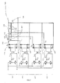
- the interleaved LLC convertors with current sharing in the aforesaid embodiments all comprise two parallel connected LLC circuits. There are four LLC circuits 401 parallel connected in the embodiment shown in FIG. 7 which shows that the interleaved LLC convertor with current sharing can be used with any even number of interleaved LLC circuits connected in parallel.
- the interleaved LLC convertor with current sharing 700 consists of an interleaved LLC circuit which is constituted by four LLC circuits 401 connected in parallel, and a coupled inductor 402.
- the LLC circuits 401 could be of any commercially available device having common LLC topology.
- the coupled inductor 402 consists of four windings 403 and a closed magnetic core 404, positioned between the output diode 405 of the LLC circuit 401 and the output capacitor 406 of the interleaved LLC convertor with current sharing 700.
- the positive terminals 407 at the DC output side of the four LLC circuits 401 together constitute the second output terminal 408; and the first terminal 409 of the four windings 403 together constitute the second output terminal 410.
- two of the four windings 403 surround the magnetic core 404 in a first direction
- the other two of the four windings 403 surround the magnetic core 404 in a second direction.
- the four windings 403 have equal inductance, and constitute inverse coupling on the magnetic core 404.
- the negative terminals 411 at the DC output side of the four LLC circuits are connected to the second terminals 412 of the four windings 403 respectively (i.e. the terminals not together constituting the second output terminal 410 with the other winding 403).
- the aforesaid output capacitor 406 is connected between the first output terminal 408 and the second output terminal 410; the output capacitor 406 is a common capacitor which can found in the market, such as film capacitor or electrolytic capacitor.
Landscapes
- Engineering & Computer Science (AREA)
- Power Engineering (AREA)
- Dc-Dc Converters (AREA)
Abstract
Description
- The present invention generally relates to an LLC convertor, and more particularly, to an interleaved LLC convertor with current sharing.
- LLC topology (as shown in
FIG.1 ) is widely used in various kinds of products, such as LCD TV, networking power supply etc. LLC has at least following advantages: a) achieving ZVS for switching transistors without extra circuits, meeting the requirement of high frequency and high efficiency at the same time; b) ZCS for secondary rectification at the secondary side and low voltage stress, which contribute to high efficiency, therefore being very suitable for two stage topology with PFC as its first stage to improve the efficiency of AC input and DC output; c) no output inductance and low cost; and d) easy for magnetic integration in the applications lower than 500W. - LLC topology is widely used due to the above advantages. However, LLC has no output filter inductance, which means, in order to solve the problem of large current ripple, a lot of capacitors connected in parallel in the output terminal are required to absorb the current ripple, especially in the low output voltage/high current/high power applications. Compared with the regular LLC topology, interleaved LLC topology (as shown in
FIG.2 ) can solve the current ripple problem significantly, and reduce the stress on the capacitors, which makes interleaved LLC a better solution in high power or high current level applications. In the interleaved LLC, two LLC convertors operate in parallel under the condition that there is 90° phase difference between the drivers. The parameters of the two resonant cavities may not be completely consistent with each other in practical application. Given the interleaved LLC has the same output voltage, the gain would be the same. When there is a tolerance between the parameters of the two resonant cavities, the following would happen:

- As shown above, when the parameters of the two resonant cavities are not consistent with each other, the two transformers, T1& T2, of the interleaved LLC, will be under different load conditions. And the worse the tolerance between the resonant parameters is, the more serious the current unbalance would be. As shown in
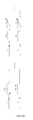
FIG.3 , when a 900W HB (Half-Bridge) interleaved LLC having resonant parameters with ±5% tolerance operates at full load, the current output I01 of one of the LLC convertors would be almost zero and thus under light load condition. In practical application, under the worst tolerance condition, one of the LLC is at light load, while the other LLC convertor has been already overloaded or even damaged when the condition is really serious. Unfortunately, to accurately learn the resonant parameters (resonant inductance Lr, resonant capacitance Cr) is always very difficult for an interleaved LLC, which becomes the bottleneck of the application of the interleaved LLC. - The present invention intends to overcome the current sharing issue of the interleaved LLC and use it in high power, high current and high frequency applications. An interleaved LLC convertor with current sharing is provided in the present invention to solve this technical problem. The interleaved LLC convertor with current sharing comprises: an interleaved LLC circuit, consisting of an even number of LLC circuits connected in parallel; and a plurality of windings with the same quantity as that of the LLC circuits. In the interleaved LLC convertor with current sharing, all first polarization terminals of each of LLC circuits at its DC output side together constitute a first output terminal; all first terminals of each of the windings together constitute a second output terminal; a first half of the plurality of windings surround a magnetic core in a first direction, and a second half of the plurality of windings surround the magnetic core in a second direction; each of the plurality of windings has the same inductance, and the first half of the plurality of windings are inversely coupled with the second half of the plurality of windings; and the second polarization terminal of each LLC circuit at its DC output side connects to a second terminal of one of the windings.
- As an improvement of the present invention, based on said interleaved LLC convertor with current sharing, the interleaved LLC convertor with current sharing further comprises an output capacitor connected between the first output terminal and the second output terminal. As another improvement of the present invention, said output capacitor is an electrolytic capacitor.
- As a further improvement of the present invention, the magnetic core in said interleaved LLC convertor with current sharing is closed magnetic core.
- As a further improvement of the present invention, the interleaved LLC circuit in the interleaved LLC convertor with current sharing consists of two LLC circuits connected in parallel.
- As a further improvement of the present invention, the inductance of the winding in said interleaved LLC convertor with current sharing is no more than Lr /n2, wherein n is the turn ratio of transformer of the LLC circuit, L r is the inductance of the resonant inductor in the LLC circuit if the plurality of windings are not included in the interleaved LLC convertor with current sharing. As a further improvement of the present invention, the inductance of said winding is no more than Lr /(2·n2)
- As a further improvement of the present invention, the tolerance of the resonant parameters (resonant inductance Lr, resonant capacitance Cr) of the LLC circuit in said interleaved LLC convertor with current sharing is no more than 10%.
-
-
FIG. 1 illustrates a topological diagram of a HB LLC according to prior art; -
FIG. 2 illustrates a topological diagram of an interleaved LLC according to prior art; -
FIG. 3 illustrates a diagram of current simulation waveform with 5% tolerance of L r & C r. -
FIG.4a illustrates a topological diagram according to an embodiment of the present invention. -
FIG.4b illustrates a diagram of the working principle of coupled inductors. -
FIG.5a illustrates a topological diagram according to an embodiment of the present invention. -
FIG.5b illustrates an output current waveform according to the embodiment shown inFIG.5a , wherein the 5% component tolerance is not included. -
FIG.5c illustrates an output current waveform according to the embodiment shown inFIG.5a with the 5% component tolerance. -
FIG.6 illustrates a topological diagram according to an embodiment of the present invention. -
FIG.7 illustrates a topological diagram according to an embodiment of the present invention. - To make the purpose, technical solution and advantages of the present invention fully understood, the present invention will now be discussed in further detail below with reference to the aforesaid figures. It should be understood that the description of the preferred embodiments herein is only for illustration purpose, not as any limitation to the present invention.
- By invoking the current sharing effect of coupled inductor, an interleaved LLC convertor with
current sharing 400, as shown inFIG.4a is provided according to an embodiment of the present invention. The interleaved LLC convertor withcurrent sharing 400 comprises an interleaved LLC circuit which consists of twoLLC circuits 401 connected in parallel, and a coupledinductor 402. TheLLC circuits 401 could be of any commercially available LLC topology. The coupledinductor 402 consists of twowindings 403 and amagnetic core 404, positioned between theoutput diode 405 of theLLC circuit 401 and theoutput capacitor 406 of the LLC convertor withcurrent sharing 400. Themagnetic core 404 may be opened magnetic core or closed magnetic core. Preferably, the magnetic core is a closed magnetic core. By using the closed magnetic core, there is less interference to the surrounding components, and it is easier to fabricate the inductors with a plurality of windings. As shown inFIG.4a , thepositive terminals 407 of the two LLC circuits at their DC output sides together constitute afirst output terminal 408; and thefirst terminals 409 of the twowindings 403 together constitute asecond terminal 410. And one of the two windings surround themagnetic core 404 in a first direction, while the other one of the two windings surround themagnetic core 404 in a second direction. Each of the two windings has the same inductance, and inversely coupled with each other on themagnetic core 404. Moreover, thenegative terminals 411 of each of the twoLLC circuits 401 at its DC output side connects to second terminals 412 (i.e. the terminals not constituting thesecond output terminal 410 with the other winding 403) of the twowindings 403 respectively. Saidoutput capacitor 406 is connected between thefirst output terminal 408 and thesecond output terminal 410; theoutput capacitor 406 is a common capacitor which is available in the market, such as film capacitor or electrolytic capacitor. - The embodiment shown in
FIG.4a can be taken as the resonant inductances Lr of T1&T2 in a simple interleaved LLC circuit (seeFIG.2 ) being split respectively into L r1 &L 1 and Lr2 &L2 , wherein L r1 &L r2 are positioned in the resonant cavity and involved in resonance, and the inductance of them is α· Lr (α is the coefficient of the inductance shared by resonant inductance at the primary side); each of L 1 &L 2 is respectively the inductance generated on themagnetic core 404 by the twowindings 403 coupled with each other and positioned after theoutput diodes 405, and each of the inductances is (1-α) · Lr /n 2 , wherein n is the turn ratio of transformer. The interleaved LLC would make use of the portion of the coupledinductor 402 in the secondary side so that, when the current of theLLC circuits 401 is unbalance, different mutual inductance will be generated on the coupledinductor 402 due to the effect of current and can be added to the primary side and involved in the resonance during operation, thus achieving the current sharing. According to the aforesaid description, α should be above zero, or the LLC circuit would no longer exist since there is no inductance at the primary side at all. Hence, when α is above zero, each of the inductances at the secondary side L 1 &L 2 is less than Lr /n2 according to an embodiment of the present invention. Since higher the inductance of the coupledinductor 403 is, higher the voltage stress bared by thediode 405 would be, the inductance of the coupled inductor should not be too high, considering the efficiency issue and the stress on theoutput diode 405 given by the coupledinductor 402. Therefore, each of the inductances at the secondary side L 1&L 2 is no more than Lr /(2 · n2). - The operating frequency of each of the
LLC circuits 401 in the interleaved LLC convertor withcurrent sharing 400 may be different. However, the operating frequencies of theLLC circuits 401 in the interleaved LLC convertor withcurrent sharing 400 are equal according to a preferred embodiment of the present invention. According to this embodiment, because the operating frequencies of theLLC circuits 401 are equal, we can use a controller (not shown inFIG.4a ) to control all theLLC circuits 401 which constitute the interleavedLLC circuit 400. Compared with the device with different operating frequencies, the device with such control method is easier to be controlled with lower manufacture cost. - There is no limitation on the difference of the phase angles of the
LLC circuits 401 in the interleaved LLC convertor withcurrent sharing 400, when theLLC circuits 401 operate in parallel. However, the difference of the phase angles of theLLC circuits 401 in the interleaved LLC convertor withcurrent sharing 400 is 180/N degree, when theLLC circuits 401 operate in parallel, according to a preferred embodiment of the present invention, wherein N is the quantity of theLLC circuits 401. When the difference of the phase angles is 180/N degree, the output current ripple is of its minimum amount; and compared with the device in which the difference of the phase angles between each of theLLC circuits 401 is not 180/N degree, theoutput capacitance 406 needed in the device according to this embodiment is smaller. - The LLC convertor with
current sharing 400 may also be connected to a single input power source or multiple different input power sources. However, according to a preferred embodiment, the LLC convertor with current sharing also includes a singleinput power source 413, and the single input power source 413is suitable for the implementation of a topology of two stages (not shown inFig.4a ) in which the former is of high power/high current PFC. Since current sharing circuits can be configured in such structure, the integration level of the module is improved, and the application of high power level is simplified. - There are certain tolerances in all of the component parameters of the
LLC circuit 401, and the orientations and the specific values of the tolerances are difficult to be controlled accurately, in practical applications. Normally, the component tolerance can only be controlled within a certain percentage. According to an embodiment of the present invention, the tolerance of the resonant parameters of theLLC circuit 401 is no more than 10%. Since bigger the deviation allowed by the components of the LLC circuit is, higher the coupled inductance 402needed to achieve the current sharing accuracy as required is, thus higher the voltage stress thediode 405 suffers, therefore the parameter tolerance of the components of theLLC circuit 401 should be controlled as possible. Preferably, the tolerance of the components of the LLC circuit 401 (resonant inductance Lr, resonant capacitance Cr) is no more than 5%. - As aforesaid, the tolerance of the component parameters of the
LLC circuit 401 is hard to be controlled. Therefore, compared with controlling the tolerance of the parameters of theLLC circuit 401, a more practicable way of current sharing is to keep the distribution of the resonant inductances in the resonant cavities Tx1&Tx2 consistent with each other:
and
wherein n is the turn ratio of transformer; L r1 is the resonant inductance positioned in the primary side after the coupledinductor 402 is joined into the circuit, L r1 ' is the resonant inductance positioned in the primary side before the coupled inductor is joined into the circuit. Referring toFIG.4b , as for the coupledinductor 402 with inductance of L:


and - L r02=L 2+L 12, wherein L r01&L r02 are the inductance after the combined effect of the actual inductance of the coupled
inductor 402 and the mutual inductance; L 12 &L 21 are the mutual inductances with mutual effect. Thus, when I 01>I 02, for:

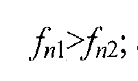
and - Q1<Q2, so I 01<I 02. Thus, the coupled
inductor 402 in the embodiment as shown inFIG.4a can carry out negative feedback, so that the current sharing between the twoLLC circuits 401 can be achieved. - Referring now to
FIG.5a , according to another embodiment of the present invention, the interleaved LLC convertor withcurrent sharing 500 consists of 900W interleaved HB LLC. The interleaved LLC circuit comprises twoLLC circuits 401, and coupledinductor 402 which consists of twowindings 403 of same inductance values inversely surrounding the closedmagnetic core 404. The rest parameters of the interleaved LLC convertor with current sharing 500 according to the present embodiment are as following described: Lr =25µH; Cr =64nF; Lm =120µH; operating frequency is 125kHz; the actual turn radio of transformer is 15: 4; the output load R=3 Ω. When the component tolerance of theLLC circuit 401 is ± 5% and under the worst condition,C r1=1.05·Cr , C r2=0.95·Cr, , and the current sharing accuracy of the interleaved LLC convertor with current sharing 500 can be expected to reach 10%. Under the condition of the component tolerance of 5%, L r1=α · Lr · 1.05 and L r2=α· Lr · 0.95. The inductance which should be distributed to the secondary side before considering different mutual inductance is k, wherein k varies between 0 to (1-α) Lr . When α =0.6, the gain range calculated is 1.02∼1.07. Based on the simulation conditions above, the inductances can be distributed as 15µH and 10µH, and if there is no component tolerance in the two LLC circuits, the waveform of the output current of the two LLC circuits would be as shown inFIG.5b ; and if the tolerance of the parameter Tx1 of the resonant cavity increase +5% and the tolerance of the parameter Tx2 of the resonant cavity increase -5%, the waveform of output current of the two LLC circuits would be as shown inFIG.5c . Under the condition in which there is no component tolerance as shown inFIG. 5a , the output current I 01 & I 02 would be in a balanced state; under the condition in which there is ±5% component tolerance as shown inFIG.5c , the output current I (SP) & I (PM) can also achieve the 10% current sharing accuracy. Thus the interleaved LLC convertor with current sharing 500 can advantageously overcome the unbalanced current distribution issue in the prior art which is caused by the unpredictable parameters of the resonant cavity of LLC. - The two LLC circuits in the interleaved LLC convertor with current sharing shown in the aforesaid embodiments (
FIG.4a ,5a ) are both connected to the coupled inductors by the negative terminals of the diodes of the output terminals at the DC side. As shown inFIG.6 , in the interleaved LLC convertor with current sharing 600 in an embodiment according to the present invention, the twoLLC circuits 401 are connected to the coupledinductors 402 by thepositive terminals 407 of the diodes of the output terminals at DC side. When the two LLC circuits are connected to the coupledinductor 402 by thepositive terminals 407 of thediodes 405, all of thenegative terminals 411 at the DC output side of theLLC circuits 401 together constitute afirst output terminal 408; and thefirst terminals 409 of the twowindings 403 together constitute asecond output terminal 410. Then one of the twowindings 403 winds surround themagnetic core 404 of the coupledinductor 402 in a first direction, and the other of the two windings surround themagnetic core 404 in a second direction. Different from the embodiments shown inFIG.4a &5a , thepositive terminals 407 at the DC side of the twoLLC circuits 401 are connected to thesecond terminals 412 of the twowindings 403 respectively (i.e. the terminals not together constituting thesecond output terminal 410 with the other winding 403). As the same as in the embodiments shown inFIG. 4a &5a , the twowindings 403 according to the present embodiment have equal inductance, and constitute inverse coupling on themagnetic core 404; and theoutput capacitor 406 is connected between thefirst output terminal 408 and thesecond terminal 410. Though the polarizations of coupling are different, there is no difference between the present embodiment and the embodiments shown inFIG. 4a &5a , as for the current sharing effect. - The interleaved LLC convertors with current sharing in the aforesaid embodiments all comprise two parallel connected LLC circuits. There are four
LLC circuits 401 parallel connected in the embodiment shown inFIG. 7 which shows that the interleaved LLC convertor with current sharing can be used with any even number of interleaved LLC circuits connected in parallel. Referring now toFIG.7 , in an embodiment according to the present invention, the interleaved LLC convertor withcurrent sharing 700 consists of an interleaved LLC circuit which is constituted by fourLLC circuits 401 connected in parallel, and a coupledinductor 402. TheLLC circuits 401 could be of any commercially available device having common LLC topology. The coupledinductor 402 consists of fourwindings 403 and a closedmagnetic core 404, positioned between theoutput diode 405 of theLLC circuit 401 and theoutput capacitor 406 of the interleaved LLC convertor withcurrent sharing 700. As shown inFIG.7 , thepositive terminals 407 at the DC output side of the fourLLC circuits 401 together constitute thesecond output terminal 408; and thefirst terminal 409 of the fourwindings 403 together constitute thesecond output terminal 410. Then two of the fourwindings 403 surround themagnetic core 404 in a first direction, the other two of the fourwindings 403 surround themagnetic core 404 in a second direction. The fourwindings 403 have equal inductance, and constitute inverse coupling on themagnetic core 404. Last but not the least, thenegative terminals 411 at the DC output side of the four LLC circuits are connected to thesecond terminals 412 of the fourwindings 403 respectively (i.e. the terminals not together constituting thesecond output terminal 410 with the other winding 403). Theaforesaid output capacitor 406 is connected between thefirst output terminal 408 and thesecond output terminal 410; theoutput capacitor 406 is a common capacitor which can found in the market, such as film capacitor or electrolytic capacitor. - It should be understood that the features and operations of the invention as described in detail are susceptible to modification and improvement without departing from the spirit and scope of the invention as claimed below. Thus the scope of the claimed technical solution is not limited by any certain embodiment above-mentioned.
Claims (10)
- An interleaved LLC convertor with current sharing, comprising:an interleaved LLC circuit, consisting of an even number of LLC circuits connected in parallel; anda plurality of windings with the same quantity as that of the LLC circuits, each of the windings has a first terminal and a second terminal, whereinall first polarization terminals of each of LLC circuits at its DC output side together constitute a first output terminal;all first terminals of each of the windings together constitute a second output terminal;a first half of the plurality of windings surround a magnetic core in a first direction, and a second half of the plurality of windings surround the magnetic core in a second direction;each of the plurality of windings has the same inductance, and the first half of the plurality of windings are inversely coupled with the second half of the plurality of windings; andthe second polarization terminal of each LLC circuit at its DC output side connects to a second terminal of one of the windings.
- The interleaved LLC convertor with current sharing of claim 1, further comprises an output capacitor connected between the first output terminal and the second output terminal.
- The interleaved LLC convertor with current sharing of claim 1, wherein the operating frequency of each LLC circuit is equal.
- The interleaved LLC convertor with current sharing of claim 1, wherein the magnetic core is closed magnetic core.
- The interleaved LLC convertor with current sharing of claim 1, wherein the interleaved LLC circuit consists of two LLC circuits connected in parallel.
- The interleaved LLC convertor with current sharing of claim 1, wherein the difference of the phase angles of the interleaved LLC circuits, as operating in parallel, is 180/N degree and N is the quantity of the LLC circuits.
- The interleaved LLC convertor with current sharing of claim 1, further comprising a single input power source.
- The interleaved LLC convertor with current sharing according to any one of claims 1-7, wherein the inductance of the windings is no more than Lr /n2, wherein n is the turn ratio of transformer of the LLC circuit, L r is the inductance of the resonant inductor of the LLC circuit if the plurality of windings are not included in the interleaved LLC convertor with current sharing.
- The interleaved LLC convertor with current sharing according to any one of claims 1-7, wherein the inductance of the windings is no more than Lr /(2·n2), wherein n is the turn ratio of transformer of the LLC circuit, Lr is the inductance of the resonant inductor of the LLC circuit if the plurality of windings are not included in the interleaved LLC convertor with current sharing.
- The interleaved LLC convertor with current sharing according to any one of claims 1-7, wherein the tolerance of the resonant parameters of the LLC circuit, i.e. the tolerance of the resonant inductance Lr and the resonant capacitance Cr, is no more than 10%.
Applications Claiming Priority (2)
| Application Number | Priority Date | Filing Date | Title |
|---|---|---|---|
| CN201210404331.2A CN103780081B (en) | 2012-10-22 | 2012-10-22 | The equal current converter of alternating expression LLC |
| PCT/CN2013/085402 WO2014063590A1 (en) | 2012-10-22 | 2013-10-17 | Interleaved llc current equalizing converter |
Publications (2)
| Publication Number | Publication Date |
|---|---|
| EP2911285A1 true EP2911285A1 (en) | 2015-08-26 |
| EP2911285A4 EP2911285A4 (en) | 2017-02-22 |
Family
ID=50544007
Family Applications (1)
| Application Number | Title | Priority Date | Filing Date |
|---|---|---|---|
| EP13849068.5A Withdrawn EP2911285A4 (en) | 2012-10-22 | 2013-10-17 | Interleaved llc current equalizing converter |
Country Status (4)
| Country | Link |
|---|---|
| US (1) | US9735685B2 (en) |
| EP (1) | EP2911285A4 (en) |
| CN (1) | CN103780081B (en) |
| WO (1) | WO2014063590A1 (en) |
Cited By (4)
| Publication number | Priority date | Publication date | Assignee | Title |
|---|---|---|---|---|
| WO2018095797A1 (en) * | 2016-11-23 | 2018-05-31 | Danmarks Tekniske Universitet | A dual active bridge dc-dc converter comprising current balancing |
| WO2019076874A1 (en) * | 2017-10-16 | 2019-04-25 | Danmarks Tekniske Universitet | A dc-dc converter assembly |
| CN110572040A (en) * | 2019-09-24 | 2019-12-13 | 西北工业大学 | Half-bridge LLC resonant converter interleaved parallel circuit and its current sharing control method |
| EP4064540A1 (en) * | 2021-03-25 | 2022-09-28 | Silergy Semiconductor Technology (Hangzhou) Ltd | Control circuit, control method and power converter |
Families Citing this family (16)
| Publication number | Priority date | Publication date | Assignee | Title |
|---|---|---|---|---|
| JP6295173B2 (en) * | 2014-05-19 | 2018-03-14 | ローム株式会社 | Power supply |
| CN104865440B (en) * | 2015-06-01 | 2017-10-20 | 中国科学院电工研究所 | Intelligent electric energy router direct current component resonant parameter method of testing |
| CN105071669A (en) * | 2015-07-17 | 2015-11-18 | 苏州华电电气股份有限公司 | Parallel DC high voltage generator |
| US10491123B2 (en) * | 2015-09-18 | 2019-11-26 | Murata Manufacturing Co., Ltd. | Modular parallel technique for resonant converter |
| CN106712518B (en) | 2015-11-13 | 2019-03-12 | 台达电子企业管理(上海)有限公司 | Converter module, transformer module and its circuit |
| CN106998142B (en) * | 2016-01-25 | 2019-08-30 | 台达电子企业管理(上海)有限公司 | Controlled resonant converter, the inductance of multi-channel parallel integrate magnetic element and transformer integrates magnetic element |
| US9837925B1 (en) * | 2016-11-01 | 2017-12-05 | Jacobo Aguillón-García | Capacitor-less power supply |
| EP3401935B1 (en) * | 2017-05-08 | 2020-12-02 | Delta Electronics (Thailand) Public Co., Ltd. | Integrated magnetic component and power converter |
| CN107612335B (en) * | 2017-09-20 | 2019-10-25 | 武汉南华工业设备工程股份有限公司 | An Interleaved Parallel Control Method for Three-level LLC Resonant Converters |
| CN107666249B (en) * | 2017-11-03 | 2019-12-03 | 南京航空航天大学 | Parallel Control Method of LLC Resonant Converter Based on Virtual Impedance |
| CN108155815B (en) * | 2017-12-18 | 2021-04-27 | 上海交通大学 | Converter parallel current sharing circuit |
| CN111492568B (en) | 2017-12-22 | 2023-12-12 | 株式会社村田制作所 | Interleaved LLC Resonant Converter |
| TWI669898B (en) * | 2018-09-12 | 2019-08-21 | 林景源 | Interleaved llc half-bridge series resonant converter having integrated transformer |
| JP7219688B2 (en) * | 2019-09-26 | 2023-02-08 | 株式会社日立製作所 | Power conversion device and its control method |
| CN120499927A (en) | 2020-02-27 | 2025-08-15 | 台达电子工业股份有限公司 | Power module assembling structure and assembling method thereof |
| CN114928253B (en) * | 2022-07-19 | 2023-01-10 | 广东首航智慧新能源科技有限公司 | Current-sharing control method, resonance conversion circuit and power module |
Family Cites Families (18)
| Publication number | Priority date | Publication date | Assignee | Title |
|---|---|---|---|---|
| JP3357627B2 (en) | 1999-04-09 | 2002-12-16 | 株式会社三社電機製作所 | Power supply for arc processing equipment |
| JP2001268910A (en) * | 2000-03-21 | 2001-09-28 | Sansha Electric Mfg Co Ltd | Power supply |
| US6304460B1 (en) * | 2000-05-05 | 2001-10-16 | Slobodan Cuk | Switching DC-to-DC converter utilizing a soft switching technique |
| JP2003164151A (en) | 2001-11-28 | 2003-06-06 | Nissin Electric Co Ltd | Dc/dc converter |
| CN1437309A (en) * | 2002-02-08 | 2003-08-20 | 张法曾 | 'Zero-ripple reactor |
| JP4442145B2 (en) * | 2003-07-10 | 2010-03-31 | ソニー株式会社 | Power supply |
| US7239530B1 (en) * | 2005-02-17 | 2007-07-03 | Volterra Semiconductor Corporation | Apparatus for isolated switching power supply with coupled output inductors |
| CN101159411A (en) * | 2005-07-26 | 2008-04-09 | 国际整流器公司 | Multi-phase buck converter with a plurality of coupled inductors |
| US8294438B2 (en) * | 2007-06-30 | 2012-10-23 | Intel Corporation | Circuit and method for phase shedding with reverse coupled inductor |
| US7893669B2 (en) * | 2007-09-10 | 2011-02-22 | Analog Devices, Inc. | Efficient voltage converter methods and structures |
| JP2011072076A (en) * | 2009-09-24 | 2011-04-07 | Sanken Electric Co Ltd | Dc conversion device |
| CN101702854A (en) * | 2009-11-21 | 2010-05-05 | 英飞特电子(杭州)有限公司 | Circuit for multi-path LED constant current driving |
| CN201766747U (en) * | 2009-11-21 | 2011-03-16 | 英飞特电子(杭州)有限公司 | Multiple constant-current driving circuit |
| CN102405587A (en) * | 2010-05-04 | 2012-04-04 | 华为技术有限公司 | Dc/dc converter |
| CN101951159B (en) * | 2010-09-20 | 2013-04-24 | 浙江大学 | Capacitor isolated type multipath constant current output resonant mode DC/DC transformer |
| CN102638167A (en) * | 2011-02-12 | 2012-08-15 | 艾默生网络能源系统北美公司 | Parallel resonant converter circuit |
| WO2013106692A1 (en) * | 2012-01-13 | 2013-07-18 | Power-One, Inc. | Resonant converter with auxiliary resonant components and holdup time control circuitry |
| US8929109B2 (en) * | 2012-11-30 | 2015-01-06 | Chung-Shan Institute Of Science And Technology | Double-output half-bridge LLC serial resonant converter |
-
2012
- 2012-10-22 CN CN201210404331.2A patent/CN103780081B/en not_active Expired - Fee Related
-
2013
- 2013-10-17 US US14/437,416 patent/US9735685B2/en active Active
- 2013-10-17 WO PCT/CN2013/085402 patent/WO2014063590A1/en not_active Ceased
- 2013-10-17 EP EP13849068.5A patent/EP2911285A4/en not_active Withdrawn
Non-Patent Citations (1)
| Title |
|---|
| See references of WO2014063590A1 * |
Cited By (5)
| Publication number | Priority date | Publication date | Assignee | Title |
|---|---|---|---|---|
| WO2018095797A1 (en) * | 2016-11-23 | 2018-05-31 | Danmarks Tekniske Universitet | A dual active bridge dc-dc converter comprising current balancing |
| WO2019076874A1 (en) * | 2017-10-16 | 2019-04-25 | Danmarks Tekniske Universitet | A dc-dc converter assembly |
| CN110572040A (en) * | 2019-09-24 | 2019-12-13 | 西北工业大学 | Half-bridge LLC resonant converter interleaved parallel circuit and its current sharing control method |
| CN110572040B (en) * | 2019-09-24 | 2021-04-02 | 西北工业大学 | Interleaved parallel circuit of half-bridge LLC resonant converter and its current sharing control method |
| EP4064540A1 (en) * | 2021-03-25 | 2022-09-28 | Silergy Semiconductor Technology (Hangzhou) Ltd | Control circuit, control method and power converter |
Also Published As
| Publication number | Publication date |
|---|---|
| US9735685B2 (en) | 2017-08-15 |
| WO2014063590A1 (en) | 2014-05-01 |
| CN103780081B (en) | 2019-09-13 |
| CN103780081A (en) | 2014-05-07 |
| US20150357921A1 (en) | 2015-12-10 |
| EP2911285A4 (en) | 2017-02-22 |
Similar Documents
| Publication | Publication Date | Title |
|---|---|---|
| EP2911285A1 (en) | Interleaved llc current equalizing converter | |
| US10855190B2 (en) | Magnetic integrated device including multiple core columns and windings and power conversion circuit | |
| US10978957B2 (en) | Resonant converter circuit and resonant converter circuit control method | |
| US9252672B2 (en) | Method of controlling phase-shift full-bridge converter in light load operation | |
| CN101944852B (en) | Multi-phase switching power supply conversion circuit | |
| EP2600512A2 (en) | Resonant conversion circuit | |
| JP6651618B2 (en) | Bidirectional resonance conversion circuit and converter | |
| US10177671B2 (en) | Modified dual active half bridge DC/DC converter with transformer DC bias | |
| US20140063874A1 (en) | High-frequency-link power-conversion system having direct double-frequency ripple current control and method of use | |
| WO2019033603A1 (en) | Wide-range soft-switch direct-current conversion circuit and control method therefor | |
| CN106817029B (en) | Changeable DC-DC power converter for providing different output voltages | |
| CN102983745A (en) | Voltage regulation method, pre-stabilized voltage power circuit and system | |
| US20150194897A1 (en) | Power supply apparatus | |
| JP6207751B2 (en) | Power converter | |
| EP4443724A1 (en) | Dc bias suppression method and high-frequency power conversion circuit using the same | |
| CN104135154B (en) | A kind of element resonance circuit of isolated form four and control method | |
| CN206349917U (en) | A kind of resonance circuit | |
| WO2018157797A1 (en) | Full-bridge resonant converter | |
| CN102098842B (en) | Current transformer-based light-emitting diode (LED) driving circuit | |
| CN106452079A (en) | N-phase resonant converter and power supply circuit | |
| CN205092776U (en) | Modular quasi -resonance is turned over and is swashed framework circuit | |
| CN105720819B (en) | A kind of two-way resonance converter | |
| Chen et al. | General method for constructing multi‐input high‐boost DC‐DC converters with low spike current | |
| CN108616215A (en) | a kind of resonance circuit | |
| Molina et al. | Three-phase buck type rectifier topology integrated with current fed full-bridge |
Legal Events
| Date | Code | Title | Description |
|---|---|---|---|
| PUAI | Public reference made under article 153(3) epc to a published international application that has entered the european phase |
Free format text: ORIGINAL CODE: 0009012 |
|
| 17P | Request for examination filed |
Effective date: 20150423 |
|
| AK | Designated contracting states |
Kind code of ref document: A1 Designated state(s): AL AT BE BG CH CY CZ DE DK EE ES FI FR GB GR HR HU IE IS IT LI LT LU LV MC MK MT NL NO PL PT RO RS SE SI SK SM TR |
|
| AX | Request for extension of the european patent |
Extension state: BA ME |
|
| DAX | Request for extension of the european patent (deleted) | ||
| RA4 | Supplementary search report drawn up and despatched (corrected) |
Effective date: 20170123 |
|
| RIC1 | Information provided on ipc code assigned before grant |
Ipc: H02M 1/00 20070101ALI20170117BHEP Ipc: H02M 3/28 20060101AFI20170117BHEP |
|
| 17Q | First examination report despatched |
Effective date: 20181009 |
|
| STAA | Information on the status of an ep patent application or granted ep patent |
Free format text: STATUS: THE APPLICATION IS DEEMED TO BE WITHDRAWN |
|
| 18D | Application deemed to be withdrawn |
Effective date: 20190220 |