EP2911216A1 - Cell module - Google Patents
Cell module Download PDFInfo
- Publication number
- EP2911216A1 EP2911216A1 EP13856177.4A EP13856177A EP2911216A1 EP 2911216 A1 EP2911216 A1 EP 2911216A1 EP 13856177 A EP13856177 A EP 13856177A EP 2911216 A1 EP2911216 A1 EP 2911216A1
- Authority
- EP
- European Patent Office
- Prior art keywords
- electrical
- cell module
- plate member
- bottom plate
- cell
- Prior art date
- Legal status (The legal status is an assumption and is not a legal conclusion. Google has not performed a legal analysis and makes no representation as to the accuracy of the status listed.)
- Withdrawn
Links
Images





Classifications
-
- H—ELECTRICITY
- H01—ELECTRIC ELEMENTS
- H01M—PROCESSES OR MEANS, e.g. BATTERIES, FOR THE DIRECT CONVERSION OF CHEMICAL ENERGY INTO ELECTRICAL ENERGY
- H01M10/00—Secondary cells; Manufacture thereof
- H01M10/60—Heating or cooling; Temperature control
- H01M10/65—Means for temperature control structurally associated with the cells
- H01M10/656—Means for temperature control structurally associated with the cells characterised by the type of heat-exchange fluid
- H01M10/6561—Gases
- H01M10/6563—Gases with forced flow, e.g. by blowers
-
- H—ELECTRICITY
- H01—ELECTRIC ELEMENTS
- H01M—PROCESSES OR MEANS, e.g. BATTERIES, FOR THE DIRECT CONVERSION OF CHEMICAL ENERGY INTO ELECTRICAL ENERGY
- H01M10/00—Secondary cells; Manufacture thereof
- H01M10/60—Heating or cooling; Temperature control
- H01M10/61—Types of temperature control
- H01M10/613—Cooling or keeping cold
-
- B—PERFORMING OPERATIONS; TRANSPORTING
- B60—VEHICLES IN GENERAL
- B60K—ARRANGEMENT OR MOUNTING OF PROPULSION UNITS OR OF TRANSMISSIONS IN VEHICLES; ARRANGEMENT OR MOUNTING OF PLURAL DIVERSE PRIME-MOVERS IN VEHICLES; AUXILIARY DRIVES FOR VEHICLES; INSTRUMENTATION OR DASHBOARDS FOR VEHICLES; ARRANGEMENTS IN CONNECTION WITH COOLING, AIR INTAKE, GAS EXHAUST OR FUEL SUPPLY OF PROPULSION UNITS IN VEHICLES
- B60K1/00—Arrangement or mounting of electrical propulsion units
- B60K1/04—Arrangement or mounting of electrical propulsion units of the electric storage means for propulsion
-
- B—PERFORMING OPERATIONS; TRANSPORTING
- B60—VEHICLES IN GENERAL
- B60L—PROPULSION OF ELECTRICALLY-PROPELLED VEHICLES; SUPPLYING ELECTRIC POWER FOR AUXILIARY EQUIPMENT OF ELECTRICALLY-PROPELLED VEHICLES; ELECTRODYNAMIC BRAKE SYSTEMS FOR VEHICLES IN GENERAL; MAGNETIC SUSPENSION OR LEVITATION FOR VEHICLES; MONITORING OPERATING VARIABLES OF ELECTRICALLY-PROPELLED VEHICLES; ELECTRIC SAFETY DEVICES FOR ELECTRICALLY-PROPELLED VEHICLES
- B60L50/00—Electric propulsion with power supplied within the vehicle
- B60L50/50—Electric propulsion with power supplied within the vehicle using propulsion power supplied by batteries or fuel cells
- B60L50/60—Electric propulsion with power supplied within the vehicle using propulsion power supplied by batteries or fuel cells using power supplied by batteries
- B60L50/64—Constructional details of batteries specially adapted for electric vehicles
-
- B—PERFORMING OPERATIONS; TRANSPORTING
- B60—VEHICLES IN GENERAL
- B60L—PROPULSION OF ELECTRICALLY-PROPELLED VEHICLES; SUPPLYING ELECTRIC POWER FOR AUXILIARY EQUIPMENT OF ELECTRICALLY-PROPELLED VEHICLES; ELECTRODYNAMIC BRAKE SYSTEMS FOR VEHICLES IN GENERAL; MAGNETIC SUSPENSION OR LEVITATION FOR VEHICLES; MONITORING OPERATING VARIABLES OF ELECTRICALLY-PROPELLED VEHICLES; ELECTRIC SAFETY DEVICES FOR ELECTRICALLY-PROPELLED VEHICLES
- B60L58/00—Methods or circuit arrangements for monitoring or controlling batteries or fuel cells, specially adapted for electric vehicles
- B60L58/10—Methods or circuit arrangements for monitoring or controlling batteries or fuel cells, specially adapted for electric vehicles for monitoring or controlling batteries
- B60L58/24—Methods or circuit arrangements for monitoring or controlling batteries or fuel cells, specially adapted for electric vehicles for monitoring or controlling batteries for controlling the temperature of batteries
- B60L58/26—Methods or circuit arrangements for monitoring or controlling batteries or fuel cells, specially adapted for electric vehicles for monitoring or controlling batteries for controlling the temperature of batteries by cooling
-
- H—ELECTRICITY
- H01—ELECTRIC ELEMENTS
- H01M—PROCESSES OR MEANS, e.g. BATTERIES, FOR THE DIRECT CONVERSION OF CHEMICAL ENERGY INTO ELECTRICAL ENERGY
- H01M10/00—Secondary cells; Manufacture thereof
- H01M10/60—Heating or cooling; Temperature control
- H01M10/64—Heating or cooling; Temperature control characterised by the shape of the cells
- H01M10/647—Prismatic or flat cells, e.g. pouch cells
-
- H—ELECTRICITY
- H01—ELECTRIC ELEMENTS
- H01M—PROCESSES OR MEANS, e.g. BATTERIES, FOR THE DIRECT CONVERSION OF CHEMICAL ENERGY INTO ELECTRICAL ENERGY
- H01M10/00—Secondary cells; Manufacture thereof
- H01M10/60—Heating or cooling; Temperature control
- H01M10/65—Means for temperature control structurally associated with the cells
- H01M10/655—Solid structures for heat exchange or heat conduction
- H01M10/6556—Solid parts with flow channel passages or pipes for heat exchange
- H01M10/6557—Solid parts with flow channel passages or pipes for heat exchange arranged between the cells
-
- H—ELECTRICITY
- H01—ELECTRIC ELEMENTS
- H01M—PROCESSES OR MEANS, e.g. BATTERIES, FOR THE DIRECT CONVERSION OF CHEMICAL ENERGY INTO ELECTRICAL ENERGY
- H01M50/00—Constructional details or processes of manufacture of the non-active parts of electrochemical cells other than fuel cells, e.g. hybrid cells
- H01M50/20—Mountings; Secondary casings or frames; Racks, modules or packs; Suspension devices; Shock absorbers; Transport or carrying devices; Holders
- H01M50/204—Racks, modules or packs for multiple batteries or multiple cells
- H01M50/207—Racks, modules or packs for multiple batteries or multiple cells characterised by their shape
- H01M50/209—Racks, modules or packs for multiple batteries or multiple cells characterised by their shape adapted for prismatic or rectangular cells
-
- H—ELECTRICITY
- H01—ELECTRIC ELEMENTS
- H01M—PROCESSES OR MEANS, e.g. BATTERIES, FOR THE DIRECT CONVERSION OF CHEMICAL ENERGY INTO ELECTRICAL ENERGY
- H01M50/00—Constructional details or processes of manufacture of the non-active parts of electrochemical cells other than fuel cells, e.g. hybrid cells
- H01M50/20—Mountings; Secondary casings or frames; Racks, modules or packs; Suspension devices; Shock absorbers; Transport or carrying devices; Holders
- H01M50/289—Mountings; Secondary casings or frames; Racks, modules or packs; Suspension devices; Shock absorbers; Transport or carrying devices; Holders characterised by spacing elements or positioning means within frames, racks or packs
-
- B—PERFORMING OPERATIONS; TRANSPORTING
- B60—VEHICLES IN GENERAL
- B60L—PROPULSION OF ELECTRICALLY-PROPELLED VEHICLES; SUPPLYING ELECTRIC POWER FOR AUXILIARY EQUIPMENT OF ELECTRICALLY-PROPELLED VEHICLES; ELECTRODYNAMIC BRAKE SYSTEMS FOR VEHICLES IN GENERAL; MAGNETIC SUSPENSION OR LEVITATION FOR VEHICLES; MONITORING OPERATING VARIABLES OF ELECTRICALLY-PROPELLED VEHICLES; ELECTRIC SAFETY DEVICES FOR ELECTRICALLY-PROPELLED VEHICLES
- B60L2240/00—Control parameters of input or output; Target parameters
- B60L2240/40—Drive Train control parameters
- B60L2240/54—Drive Train control parameters related to batteries
- B60L2240/545—Temperature
-
- Y—GENERAL TAGGING OF NEW TECHNOLOGICAL DEVELOPMENTS; GENERAL TAGGING OF CROSS-SECTIONAL TECHNOLOGIES SPANNING OVER SEVERAL SECTIONS OF THE IPC; TECHNICAL SUBJECTS COVERED BY FORMER USPC CROSS-REFERENCE ART COLLECTIONS [XRACs] AND DIGESTS
- Y02—TECHNOLOGIES OR APPLICATIONS FOR MITIGATION OR ADAPTATION AGAINST CLIMATE CHANGE
- Y02E—REDUCTION OF GREENHOUSE GAS [GHG] EMISSIONS, RELATED TO ENERGY GENERATION, TRANSMISSION OR DISTRIBUTION
- Y02E60/00—Enabling technologies; Technologies with a potential or indirect contribution to GHG emissions mitigation
- Y02E60/10—Energy storage using batteries
-
- Y—GENERAL TAGGING OF NEW TECHNOLOGICAL DEVELOPMENTS; GENERAL TAGGING OF CROSS-SECTIONAL TECHNOLOGIES SPANNING OVER SEVERAL SECTIONS OF THE IPC; TECHNICAL SUBJECTS COVERED BY FORMER USPC CROSS-REFERENCE ART COLLECTIONS [XRACs] AND DIGESTS
- Y02—TECHNOLOGIES OR APPLICATIONS FOR MITIGATION OR ADAPTATION AGAINST CLIMATE CHANGE
- Y02T—CLIMATE CHANGE MITIGATION TECHNOLOGIES RELATED TO TRANSPORTATION
- Y02T10/00—Road transport of goods or passengers
- Y02T10/60—Other road transportation technologies with climate change mitigation effect
- Y02T10/70—Energy storage systems for electromobility, e.g. batteries
Definitions
- the present invention relates to a cell module including a battery pack in which a plurality of cells are arranged.
- a cell module including a bottom plate member that supports a battery pack from below is known.
- this type of cell module there is known a technique of making through-holes through which cooling wind passes in a vertical direction in the bottom plate member in order to efficiently cool the battery pack (for example, refer to Patent Document 1).
- Patent Document 1 Japanese Unexamined Patent Application, First Publication No. 2011-096398
- a cell module includes a battery pack in which a plurality of electrical cells are arranged; and a bottom plate member that supports the battery pack.
- the bottom plate member includes an ejector for ejecting a liquid on the bottom plate member in a direction intersecting in an arrangement direction of the electrical cells and in an extending direction of the bottom plate member.
- the ejector may include a first inclination surface that inclines toward the direction in which the liquid is ejected.
- the bottom plate member may include a groove portion that is recessed in a direction separating from a bottom surface of the electrical cell and extends in the direction in which the liquid is ejected, and a supporting portion that contacts with the bottom surface of the electrical cell, and the groove portion may be provided between the supporting portions adjacent to each other in the arrangement direction of the electrical cells.
- the groove portion may include a first inclination surface, which inclines toward the direction in which the liquid is ejected, on the bottom portion of the groove portion.
- the bottom plate member may include a second inclination surface that inclines so as to separate from the bottom surface of the electrical cell, from the supporting portion toward the groove portion.
- the supporting portion may linearly contact with the bottom surface of the electrical cell in the direction intersecting the arrangement direction of the electrical cells and in the extending direction of the bottom plate member.
- an insulating plate that performs electrical insulation between cases of the electrical cells adjacent to each other may be provided between the cases of the electrical cells, and the entire edge portion of the insulating plate on the bottom plate member side may contact with the bottom plate member.
- the ejector in the cell module of the seventh aspect, may be provided between the insulating plates.
- FIG. 1 illustrates the cell module 1 of this embodiment.
- the cell module 1 includes a battery pack 11.
- the battery pack 11 is formed by arranging a plurality of electrical cells 10 in a row in the thickness direction thereof.
- Each electrical cell 10 is formed in a substantially rectangular parallelepiped shape that has electrodes (not illustrated) formed at an upper portion thereof.
- the electrodes of the respective electrical cells 10 are connected in series or in parallel by tie-bars (not illustrated) or the like.
- the battery pack 11 includes a flat plate-shaped insulating member (insulating plate) 12 between the electrical cells 10 adjacent to each other. Primarily, the insulating member electrically insulates facing wall surfaces of cases C of the respective electrical cells 10.
- the cell module 1 includes a casing 13 that houses the battery pack 11.
- the casing 13 includes two side frames 14 and two support frames 15.
- Each side frame 14 is formed like a belt.
- the two side frames surround an upper portion and a lower portion of the battery pack 11.
- Each support frame 15 is formed like a belt that that extends in a vertical direction.
- the support frame 15 combines the two side frames 14 at both ends in an arrangement direction of the electrical cells 10 (hereinafter simply referred to as an arrangement direction).
- the casing 13 has side plates 16 that cover end surfaces of the battery pack 11, at both of the ends in the arrangement direction.
- Each side plate 16 has a flange portion 17, which is bent inward in the arrangement direction, at a lower edge thereof.
- Each flange portion 17 is arranged so as to go around to a bottom surface 34 side of the battery pack 11.
- the side frames 14 are fixed to the side plate 16.
- Inner plates 19 are disposed inside the side plates 16 in the arrangement direction.
- Each inner plate 19 includes a bent portion 18.
- the bent portion 18 is formed by bending an outer edge of the inner plate 19 in its width direction so as to go around to a side surface side of the battery pack 11 in its width direction.
- a direction that intersects the arrangement direction of the electrical cells 10, and an extending direction of the support plate 30 to be described below are each simply referred to as a width direction.
- the casing 13 further has an upper cover 20 that covers the upper portion of the battery pack 11.
- the upper cover 20 is provided to prevent water, dust, or the like from adhering to the respective electrodes of the electrical cells 10 and the tie-bars.
- An upper inclination surface 21 formed at the upper cover 20 is formed with an access hole 22 for inserting wiring lines that perform electrical connection.
- the casing 13 includes a support plate (bottom plate member) 30 that supports the battery pack 11 from below.
- the support plate 30 has support plate portions 30a on both sides in the arrangement direction. Each support plate portion 30a is supported by the flange portion 17 of the side plate 16.
- the support plate 30 includes a main plate portion 31 and side wall portions 32.
- the main plate portion 31 supports the bottom surface 34 of the battery pack 11 from below.
- the side wall portions 32 regulate displacement the battery pack 11 in the width direction.
- the side wall portions 32 are formed so as to rise upward from both sides in a width direction of the main plate portion 31 orthogonal to the arrangement direction.
- the main plate portion 31 is provided with a plurality of ejection portions (ejector) 33 that eject a liquid, such as water that is present on the support plate 30, due to the self-weight of the liquid.
- the ejection portions 33 are formed side by side in the arrangement direction.
- Each ejection portion 33 includes a supporting portion 36, an array-side inclination surface 37, and a width-side inclination surface 38 (first inclination surface).
- the supporting portion 36 includes a first supporting portion 35 that linearly contacts with the bottom surface 34 of the electrical cell 10 at the center in the arrangement direction.
- the array-side inclination surface 37 is formed so as to come down toward both sides in the arrangement direction from the first supporting portion 35.
- the width-side inclination surface 38 is connected to a lower edge of the array-side inclination surface 37 and is inclinedly formed to incline so as to come down toward the outsides in the width direction.
- Groove portions 40 which extend toward the width direction, are further formed at positions below facing surfaces 39 (refer to FIG. 5 ) of the respective adjacent electrical cells 10, between the first supporting portions 35 adjacent to each other in the arrangement direction.
- Each groove portion 40 is formed so as to be recessed in a direction separating from the bottom surface 34 of the electrical cell 10.
- a groove bottom surface 41 (first inclination surface) of the groove portion 40 is inclinedly formed so as to come down toward the outsides in the width direction.
- the width of the groove portion 40 is formed with a substantially constant width that is more sufficient than a gap between the cases C that form the outlines of the respective electrical cells 10.
- the above-described array-side inclination surface (second inclination surface) 37 inclines so as to separate from the bottom surface 34 of the electrical cell 10 from the first supporting portion 35 toward the groove portion 40.
- the first inclination surface is a surface that inclines toward a direction in which water is ejected, and is the width-side inclination surface 37 and the groove bottom surface 41.
- the width-side inclination surface 37 and the groove bottom surface 41 incline will be described as an example.
- the width-side inclination surface 37 may incline toward the groove portion 40, or the groove bottom surface 41 incline may not incline but may be made horizontal.
- the array-side inclination surface 38 is not limited to a case where the array-side inclination surface is formed so as to come down from the first supporting portion 35 toward both sides in the arrangement direction.
- the array-side inclination surface 38 may be omitted together with the width-side inclination surface 37.
- the supporting portion 36 includes a second supporting portion 42 that linearly contacts with the bottom surface 34 of the electrical cell 10 at the center in the width direction.
- the second supporting portion 42 is intermittently formed in the arrangement direction excluding places where the groove portions 40 are formed.
- the width-side inclination surface 38 inclines so as to come down from the second supporting portion 42 toward both sides in the width direction.
- a central portion of the groove bottom surface 41 in the width direction is the highest.
- the groove bottom surface 41 inclines so as to come down toward both sides in the width direction.
- the central portion of the groove bottom surface 41 in the width direction is arranged below a central portion of the width-side inclination surface 38 in the width direction, in the vertical direction.
- the width-side inclination surface 38 and the array-side inclination surface 37 may not be limited to being planar surfaces, but may be slightly concavely or convexly curved surfaces.
- the array-side inclination surface 37 is formed such that the width dimension thereof in the arrangement direction becomes smaller toward the center in the width direction.
- the width-side inclination surface 38 is formed such that the width dimension thereof in the arrangement direction becomes smaller toward the outsides in the width direction.
- a ridgeline formed by the two array-side inclination surfaces 37 adjacent to each other in the arrangement direction constitutes the first supporting portion 35.
- a ridgeline formed by the two width-side inclination surface 38 adjacent to each other in the width direction constitutes the second supporting portion 42.
- the side wall portion 32 has a plurality of vertical walls 43 that rise from outer edge portions of the array-side inclination surface 37 and the first supporting portion 35 in the width direction. Inner surfaces 44 (refer to FIG. 3 ) of the vertical walls 43 in the width direction are connected with the array-side inclination surface 37 and the first supporting portion 35 via a concave curve 45.
- An upper connecting portion 46 is formed at the side wall portion 32 so as to bridge over upper portions of the vertical walls 43 adjacent to each other.
- a through-hole 47 which passes through the inside and the outside of the side wall portion 32 toward the outsides in the width direction, is formed by a lower side of the upper connecting portion 46, two facing side portions that are the vertical walls 43, and a lateral side portion of the main plate portion 31.
- the invention is not limited to this.
- the insulating member 12 arranged between the respective electrical cells 10 is arranged substantially at the center of the width-side inclination surface 38 in the arrangement direction.
- the insulating member 12 is arranged substantially at the center of the groove portion 40 in the arrangement direction.
- the insulating member 12 includes a shape corresponding to the inclination of the groove bottom surface 41 so as to come into close contact with the groove bottom surface 41.
- the entire edge portion of the insulating member 12 on the groove bottom surface 41 side contacts with the groove bottom surface 41. That is, the lower edge of the insulating member 12 includes an inclined bottom surface 48 that inclines from a central portion thereof in the width direction toward both sides in the width direction.
- the cell module in this embodiment includes the above configuration. Next, the operation of this cell module will be described referring to the drawings. Here, in the description of this operation, a case where dew condensation is caused by cooling the battery pack 11 with cooling wind or the like, and the water caused by this dew condensation is dropped and ejected onto the support plate 30 will be described as an example.
- the water adhering to the surface of the electrical cell 10 moves to the bottom surface 34 side along a side surface due to the self-weight thereof. Then, the water drops onto the support plate 30 or flows down along the supporting portion 36, mainly from and between a lower corner of the electrical cell 10 and a place that contact with the supporting portion 36 of the bottom surface 34.
- the water which has dropped onto the first supporting portion 35 or has flowed down via the array-side inclination surface 37, as indicated by an arrow in FIG. 2 , flows toward the downside in the arrangement direction along the array-side inclination surface 37 due to the self-weight thereof, and moves onto the width-side inclination surface 38.
- the water which has dropped onto the width-side inclination surface 38 or has flowed down via the second supporting portion 42, flows toward the outsides and the downside in the width direction along the width-side inclination surface 38 due to the self-weight thereof, and then, most of the water flows into the groove portion 40 because the width-side inclination surface 38 becomes narrower toward the outside in the width direction.
- the water within the groove portion 40 is regulated in its movement in the arrangement direction by the insulating member 12. Therefore, the water generated from the two electrical cells 10 adjacent to each other is not mixed together.
- the cell module of the above-described first embodiment it is possible to prevent that the water stagnate on the support plate 30 because a situation in which the water resulting from dew condensation or the like is ejected to the outsides in the width direction by the support plate 30 so as to bridge between the adjacent electrical cells 10. Therefore, it is possible to suppress the electrical connection between the cases of the electrical cells 10 adjacent to each other to prevent trouble, such as corrosion, from occurring.
- water can be moved due to the self-weight thereof along the inclination of the array-side inclination surface 37 or the width-side inclination surface 38. Therefore, the water on the support plate 30 can be ejected using a simple configuration.
- the bottom surface 34 of each electrical cell 10 can be supported by the supporting portion 36.
- the water adhering to each electrical cell 10 flows downward, the water can be made to flow into the groove portion 40. Therefore, even if minute shaking or the like has occurred, the water, which has flowed into the groove portion 40, can be prevented from adhering to the electrical cell 10.
- the groove bottom surface 41 of the groove portion 40 inclines, the water, which has flowed into the groove portion 40, can be smoothly ejected from the support plate 30. Moreover, since the through-hole in the vertical direction is not formed in the support plate 30, it is possible to prevent entering of water from below.
- the width-side inclination surface 38 and the groove bottom surface 41 incline from the center in the width direction toward the outside, it is possible to eject the water, which has dropped or flowed in onto the width-side inclination surface 38 and the groove bottom surface 41, to the outsides of the support plate 30 in the width direction at the shortest distance. Therefore, water can be rapidly ejected.
- a case where the width-side inclination surface 38 inclines from the central portion toward the outside in the width direction has been described in the above-described first embodiment.
- the width-side inclination surface 38 may be formed so as to incline from a first end toward a second end in the width direction.
- the second embodiment is different from the above-described first embodiment in that when the self-weight of water is not used positively when the water is ejected from on the support plate. Therefore, the same portions will be described with the same symbols attached thereto.
- the cell module of the second embodiment includes an insulating member 212 between the cases of the electrical cells 10.
- the insulating member 212 includes air passageways 50 for allowing air to flow in the vertical direction between the cases of the respective electrical cells 10. Air is supplied to these air passageways 50 from an air supplier, such as a blower (not illustrated), and air flows downward from above (indicated by an arrow in FIG. 6 ).
- a support plate (bottom plate member) 230 that supports the battery pack 11 from below includes the supporting portions 36 and groove portions 240.
- Each supporting portion 36 supports a substantially central portion of the bottom surface 34 of the electrical cell 10 in the arrangement direction from below.
- Each groove portion 240 is formed between the supporting portions 36, and is formed so as to be recessed in a direction separating from the bottom surface 34.
- the support plate 230 of the second embodiment also has the side wall portions 32 (refer to FIG. 2 ), similar to the above-described first embodiment.
- a penetration portion 47 is formed at a position where the groove portion 240 is formed.
- the groove portion 240 has a groove bottom surface 241 that extends substantially parallel to the bottom surface 34 of the electrical cell 10.
- a lower edge of the above-described insulating member 212 is arranged at a predetermined distance in the vertical direction from the groove bottom surface 241.
- the air, which is blown out through the air passageways 50 of the insulating members 212 from the lower edges thereof, is guided to the groove portions 240, respectively.
- the air guided to each groove portion 240 is ejected from the through-hole 47 to the outsides of the support plate 230 in the width direction.
- the water that has dropped or flowed into the groove portion 240 is blown away to the outsides in the width direction by the air supplied through the air passageways 50 of the insulating member 212, and is ejected on the outsides of the support plate 230 in the width direction. Therefore, the electrical connection between the cases of the electrical cells 10 can be suppressed by preventing water from stagnating between the cases of the electrical cells 10 adjacent to each other. As a result, trouble, such as corrosion, can be prevented from occurring.
- the invention is not limited to the configuration of the above-described embodiment, and design changes can be made without departing from the concept of the invention.
- the groove portion 40 in the width-side inclination surface 38 has been described in the above-described first embodiment.
- the groove portion 40 of the width-side inclination surface 38 may be omitted. In this case, it is only necessary to make the dimension, in the arrangement direction, of the end of the width-side inclination surface 38 in the width direction, approximately equal to the dimension of the through-hole 48 in the arrangement direction.
- first supporting portion 35 contacts with the central portion of the electrical cell 10 in the arrangement direction.
- the array-side inclination surface 37, the width-side inclination surface 38, and the groove portion 40 only have to be formed between the first supporting portions 35 adjacent to each other.
- a supporting portion 136 may contact with both ends of the bottom surface 34 of the electrical cell 10 in the arrangement direction, and the groove portion 40 may be disposed below the center of the bottom surface 34 in the arrangement direction.
- the groove portion 40 may be omitted even in the modified example illustrated in FIG. 9 .
- the insulating member 12 is provided with the air passageways 50 in the above-described second embodiment.
- the shape of the air passageways 50 is limited to the shape illustrated in FIG. 6 .
- an air supply source F such as a blower
- the air supplied from the air supply source F may pass through from one side of through-hole 47 toward the other side of the through-hole 47 in the width direction.
- the water in the groove portion 240 can be moved the other side by the air supplied from one side in the width direction and can be ejected from the other through-hole 47 to the outsides of the support plate 230 in the width direction.
- a bottom portion of the groove portion 240 may not be formed with the first inclination surface that inclines toward a direction in which water is ejected but may be formed with a horizontal surface.
- the groove portions 40 and 240 are formed in the width direction with a constant width.
- the groove portions 40 and 240 are not limited to having the constant width.
- the groove portions 40 and 240 may be obliquely formed with respect to the width direction.
- water has been described as an example of the fluid ejected to the outsides of the support plate 30 in the width direction.
- the fluid is not limited to water if fluids that may attach to the cell module are used.
- the casing 13 is constituted of the upper cover 20, the support frames 14 and 15, the side plate 16, the upper cover 20, and the support plate 30 has been described in the first embodiment.
- the casing 13 may have other configurations and shapes without being limited to the above-described configuration and shape except for the support plate that supports the battery pack 11 downward, or may be omitted.
- the cell module including a battery pack in which a plurality of cells are arranged, it is possible to suppress the electrical connection between the cases of the electrical cells adjacent to each other to prevent trouble, such as corrosion, from occurring.
Landscapes
- Engineering & Computer Science (AREA)
- Chemical & Material Sciences (AREA)
- Chemical Kinetics & Catalysis (AREA)
- Electrochemistry (AREA)
- General Chemical & Material Sciences (AREA)
- Manufacturing & Machinery (AREA)
- Transportation (AREA)
- Mechanical Engineering (AREA)
- Life Sciences & Earth Sciences (AREA)
- Power Engineering (AREA)
- Sustainable Energy (AREA)
- Sustainable Development (AREA)
- Combustion & Propulsion (AREA)
- Battery Mounting, Suspending (AREA)
Abstract
Description
- The present invention relates to a cell module including a battery pack in which a plurality of cells are arranged.
- Priority is claimed on Japanese Patent Application No.
2012-255698, filed November 21, 2012 - In cell modules including a battery pack in which a plurality of cells are arranged, a cell module including a bottom plate member that supports a battery pack from below is known. In this type of cell module, there is known a technique of making through-holes through which cooling wind passes in a vertical direction in the bottom plate member in order to efficiently cool the battery pack (for example, refer to Patent Document 1).
- [Patent Document 1] Japanese Unexamined Patent Application, First Publication No.
2011-096398 - However, since the through-holes are formed on the above cell module in the vertical direction, water may enter the cell module from below. Additionally, when the battery pack is cooled, dew condensation may occur. Water may drop due to this dew condensation, and the water may stagnate on the bottom plate member. Therefore, adjacent electrical cells may be electrically connected together via the water, and trouble, such as corrosion resulting from this electrical connection, may occur.
- According to a first aspect of the invention, a cell module includes a battery pack in which a plurality of electrical cells are arranged; and a bottom plate member that supports the battery pack. The bottom plate member includes an ejector for ejecting a liquid on the bottom plate member in a direction intersecting in an arrangement direction of the electrical cells and in an extending direction of the bottom plate member.
- According to a second aspect of the invention, in the cell module of the first aspect, the ejector may include a first inclination surface that inclines toward the direction in which the liquid is ejected.
- According to a third aspect of the invention, in the cell module of the first or second aspect, the bottom plate member may include a groove portion that is recessed in a direction separating from a bottom surface of the electrical cell and extends in the direction in which the liquid is ejected, and a supporting portion that contacts with the bottom surface of the electrical cell, and the groove portion may be provided between the supporting portions adjacent to each other in the arrangement direction of the electrical cells.
- According to a fourth aspect of the invention, in the cell module of the third aspect, the groove portion may include a first inclination surface, which inclines toward the direction in which the liquid is ejected, on the bottom portion of the groove portion.
- According to a fifth aspect of the invention, in the cell module of the third or fourth aspect, the bottom plate member may include a second inclination surface that inclines so as to separate from the bottom surface of the electrical cell, from the supporting portion toward the groove portion.
- According to a sixth aspect of the invention, in the cell module of any one aspect of the third to fifth aspects, the supporting portion may linearly contact with the bottom surface of the electrical cell in the direction intersecting the arrangement direction of the electrical cells and in the extending direction of the bottom plate member.
- According to a seventh aspect of the invention, in the cell module of any one aspect of the third to sixth aspects, an insulating plate that performs electrical insulation between cases of the electrical cells adjacent to each other may be provided between the cases of the electrical cells, and the entire edge portion of the insulating plate on the bottom plate member side may contact with the bottom plate member.
- According to an eighth aspect of the invention, in the cell module of the seventh aspect, the ejector may be provided between the insulating plates.
- According to the above-described cell module, it is possible to suppress the electrical connection between the cases of the electrical cells adjacent to each other to prevent trouble, such as corrosion, from occurring.
-
-
FIG. 1 is a perspective view of a cell module in a first embodiment of the invention. -
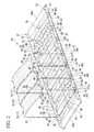
FIG. 2 is a perspective view illustrating a support plate of the cell module in the first embodiment of the invention. -
FIG. 3 is an enlarged perspective of lower portions of electrical cells supported by the support plate in the first embodiment. -
FIG. 4 is a partial cross-sectional view illustrating a contact state between an insulating member and the support plate that are arranged between the electrical cells in the first embodiment. -
FIG. 5 is a cross-sectional view taken along line A-A ofFIG. 2 . -
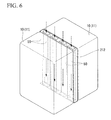
FIG. 6 is a perspective view illustrating an insulating member between electrical cells in a second embodiment of the invention. -
FIG. 7 is a cross-sectional view corresponding toFIG. 5 in the second embodiment. -
FIG. 8 is a cross-sectional view taken along line B-B ofFIG. 7 . -
FIG. 9 is a cross-sectional view corresponding toFIG. 5 in a modified example of the first embodiment. -
FIG. 10 is a cross-sectional view corresponding toFIG. 8 in a modified example of the second embodiment. - Next, a cell module 1 in a first embodiment of the invention will be described with reference to the drawing.
-
FIG. 1 illustrates the cell module 1 of this embodiment. As illustrated inFIG. 1 , the cell module 1 includes abattery pack 11. Thebattery pack 11 is formed by arranging a plurality ofelectrical cells 10 in a row in the thickness direction thereof. Eachelectrical cell 10 is formed in a substantially rectangular parallelepiped shape that has electrodes (not illustrated) formed at an upper portion thereof. The electrodes of the respectiveelectrical cells 10 are connected in series or in parallel by tie-bars (not illustrated) or the like. Thebattery pack 11 includes a flat plate-shaped insulating member (insulating plate) 12 between theelectrical cells 10 adjacent to each other. Primarily, the insulating member electrically insulates facing wall surfaces of cases C of the respectiveelectrical cells 10. - The cell module 1 includes a
casing 13 that houses thebattery pack 11. Thecasing 13 includes twoside frames 14 and twosupport frames 15. - Each
side frame 14 is formed like a belt. The two side frames surround an upper portion and a lower portion of thebattery pack 11. Eachsupport frame 15 is formed like a belt that that extends in a vertical direction. - The
support frame 15 combines the twoside frames 14 at both ends in an arrangement direction of the electrical cells 10 (hereinafter simply referred to as an arrangement direction). - The
casing 13 hasside plates 16 that cover end surfaces of thebattery pack 11, at both of the ends in the arrangement direction. Eachside plate 16 has aflange portion 17, which is bent inward in the arrangement direction, at a lower edge thereof. Eachflange portion 17 is arranged so as to go around to abottom surface 34 side of thebattery pack 11. Theside frames 14 are fixed to theside plate 16.Inner plates 19 are disposed inside theside plates 16 in the arrangement direction. Eachinner plate 19 includes abent portion 18. Thebent portion 18 is formed by bending an outer edge of theinner plate 19 in its width direction so as to go around to a side surface side of thebattery pack 11 in its width direction. In addition, a direction that intersects the arrangement direction of theelectrical cells 10, and an extending direction of thesupport plate 30 to be described below are each simply referred to as a width direction. - The
casing 13 further has anupper cover 20 that covers the upper portion of thebattery pack 11. Theupper cover 20 is provided to prevent water, dust, or the like from adhering to the respective electrodes of theelectrical cells 10 and the tie-bars. Anupper inclination surface 21 formed at theupper cover 20 is formed with anaccess hole 22 for inserting wiring lines that perform electrical connection. Thecasing 13 includes a support plate (bottom plate member) 30 that supports thebattery pack 11 from below. Thesupport plate 30 hassupport plate portions 30a on both sides in the arrangement direction. Eachsupport plate portion 30a is supported by theflange portion 17 of theside plate 16. - As illustrated in
FIG. 2 , thesupport plate 30 includes amain plate portion 31 andside wall portions 32. - The
main plate portion 31 supports thebottom surface 34 of thebattery pack 11 from below. - Primarily, the
side wall portions 32 regulate displacement thebattery pack 11 in the width direction. Theside wall portions 32 are formed so as to rise upward from both sides in a width direction of themain plate portion 31 orthogonal to the arrangement direction. - As illustrated in
FIGS. 2 and3 , themain plate portion 31 is provided with a plurality of ejection portions (ejector) 33 that eject a liquid, such as water that is present on thesupport plate 30, due to the self-weight of the liquid. Theejection portions 33 are formed side by side in the arrangement direction. Eachejection portion 33 includes a supportingportion 36, an array-side inclination surface 37, and a width-side inclination surface 38 (first inclination surface). - The supporting
portion 36 includes a first supportingportion 35 that linearly contacts with thebottom surface 34 of theelectrical cell 10 at the center in the arrangement direction. - The array-
side inclination surface 37 is formed so as to come down toward both sides in the arrangement direction from the first supportingportion 35. - The width-
side inclination surface 38 is connected to a lower edge of the array-side inclination surface 37 and is inclinedly formed to incline so as to come down toward the outsides in the width direction. -
Groove portions 40, which extend toward the width direction, are further formed at positions below facing surfaces 39 (refer toFIG. 5 ) of the respective adjacentelectrical cells 10, between the first supportingportions 35 adjacent to each other in the arrangement direction. Eachgroove portion 40 is formed so as to be recessed in a direction separating from thebottom surface 34 of theelectrical cell 10. A groove bottom surface 41 (first inclination surface) of thegroove portion 40 is inclinedly formed so as to come down toward the outsides in the width direction. The width of thegroove portion 40 is formed with a substantially constant width that is more sufficient than a gap between the cases C that form the outlines of the respectiveelectrical cells 10. The above-described array-side inclination surface (second inclination surface) 37 inclines so as to separate from thebottom surface 34 of theelectrical cell 10 from the first supportingportion 35 toward thegroove portion 40. Here, the first inclination surface is a surface that inclines toward a direction in which water is ejected, and is the width-side inclination surface 37 and thegroove bottom surface 41. Hereinafter, a case where both of the width-side inclination surface 37 and thegroove bottom surface 41 incline will be described as an example. However, the invention is not limited to this. For example, the width-side inclination surface 37 may incline toward thegroove portion 40, or thegroove bottom surface 41 incline may not incline but may be made horizontal. The array-side inclination surface 38 is not limited to a case where the array-side inclination surface is formed so as to come down from the first supportingportion 35 toward both sides in the arrangement direction. For example, the array-side inclination surface 38 may be omitted together with the width-side inclination surface 37. - The supporting
portion 36 includes a second supportingportion 42 that linearly contacts with thebottom surface 34 of theelectrical cell 10 at the center in the width direction. The second supportingportion 42 is intermittently formed in the arrangement direction excluding places where thegroove portions 40 are formed. The width-side inclination surface 38 inclines so as to come down from the second supportingportion 42 toward both sides in the width direction. A central portion of thegroove bottom surface 41 in the width direction is the highest. Thegroove bottom surface 41 inclines so as to come down toward both sides in the width direction. The central portion of thegroove bottom surface 41 in the width direction is arranged below a central portion of the width-side inclination surface 38 in the width direction, in the vertical direction. Here, the width-side inclination surface 38 and the array-side inclination surface 37 may not be limited to being planar surfaces, but may be slightly concavely or convexly curved surfaces. - The array-
side inclination surface 37 is formed such that the width dimension thereof in the arrangement direction becomes smaller toward the center in the width direction. The width-side inclination surface 38 is formed such that the width dimension thereof in the arrangement direction becomes smaller toward the outsides in the width direction. A ridgeline formed by the two array-side inclination surfaces 37 adjacent to each other in the arrangement direction constitutes the first supportingportion 35. A ridgeline formed by the two width-side inclination surface 38 adjacent to each other in the width direction constitutes the second supportingportion 42. - The
side wall portion 32 has a plurality ofvertical walls 43 that rise from outer edge portions of the array-side inclination surface 37 and the first supportingportion 35 in the width direction. Inner surfaces 44 (refer toFIG. 3 ) of thevertical walls 43 in the width direction are connected with the array-side inclination surface 37 and the first supportingportion 35 via aconcave curve 45. An upper connectingportion 46 is formed at theside wall portion 32 so as to bridge over upper portions of thevertical walls 43 adjacent to each other. A through-hole 47, which passes through the inside and the outside of theside wall portion 32 toward the outsides in the width direction, is formed by a lower side of the upper connectingportion 46, two facing side portions that are thevertical walls 43, and a lateral side portion of themain plate portion 31. Here, although an example in which theinner surface 44, the array-side inclination surface 37, and the first supportingportion 35 are connected together by theconcave curve 45 has been described, the invention is not limited to this. - As illustrated in
FIG. 3 , the insulatingmember 12 arranged between the respectiveelectrical cells 10 is arranged substantially at the center of the width-side inclination surface 38 in the arrangement direction. In other words, the insulatingmember 12 is arranged substantially at the center of thegroove portion 40 in the arrangement direction. As illustrated inFIG. 4 , the insulatingmember 12 includes a shape corresponding to the inclination of thegroove bottom surface 41 so as to come into close contact with thegroove bottom surface 41. The entire edge portion of the insulatingmember 12 on thegroove bottom surface 41 side contacts with thegroove bottom surface 41. That is, the lower edge of the insulatingmember 12 includes aninclined bottom surface 48 that inclines from a central portion thereof in the width direction toward both sides in the width direction. - The cell module in this embodiment includes the above configuration. Next, the operation of this cell module will be described referring to the drawings. Here, in the description of this operation, a case where dew condensation is caused by cooling the
battery pack 11 with cooling wind or the like, and the water caused by this dew condensation is dropped and ejected onto thesupport plate 30 will be described as an example. - First, the water adhering to the surface of the
electrical cell 10 moves to thebottom surface 34 side along a side surface due to the self-weight thereof. Then, the water drops onto thesupport plate 30 or flows down along the supportingportion 36, mainly from and between a lower corner of theelectrical cell 10 and a place that contact with the supportingportion 36 of thebottom surface 34. - In this case, the water, which has dropped onto the first supporting
portion 35 or has flowed down via the array-side inclination surface 37, as indicated by an arrow inFIG. 2 , flows toward the downside in the arrangement direction along the array-side inclination surface 37 due to the self-weight thereof, and moves onto the width-side inclination surface 38. - On the other hand, the water, which has dropped onto the width-
side inclination surface 38 or has flowed down via the second supportingportion 42, flows toward the outsides and the downside in the width direction along the width-side inclination surface 38 due to the self-weight thereof, and then, most of the water flows into thegroove portion 40 because the width-side inclination surface 38 becomes narrower toward the outside in the width direction. - The water which has directly dropped into the
groove portion 40, the water that has fallen along the insulatingmember 12, and the water that has flowed in from the width-side inclination surface 38, flows toward the outside and the downside in the width direction along the inclination of thegroove bottom surface 41 of thegroove portion 40 due to the self-weight thereof, and is ejected from the through-hole 47 of theside wall portion 32 to the outside in the width direction of thesupport plate 30. The water within thegroove portion 40 is regulated in its movement in the arrangement direction by the insulatingmember 12. Therefore, the water generated from the twoelectrical cells 10 adjacent to each other is not mixed together. - Therefore, according to the cell module of the above-described first embodiment, it is possible to prevent that the water stagnate on the
support plate 30 because a situation in which the water resulting from dew condensation or the like is ejected to the outsides in the width direction by thesupport plate 30 so as to bridge between the adjacentelectrical cells 10. Therefore, it is possible to suppress the electrical connection between the cases of theelectrical cells 10 adjacent to each other to prevent trouble, such as corrosion, from occurring. - Additionally, water can be moved due to the self-weight thereof along the inclination of the array-
side inclination surface 37 or the width-side inclination surface 38. Therefore, the water on thesupport plate 30 can be ejected using a simple configuration. - Moreover, as the
groove portion 40 is arranged between the supportingportions 36, thebottom surface 34 of eachelectrical cell 10 can be supported by the supportingportion 36. When the water adhering to eachelectrical cell 10 flows downward, the water can be made to flow into thegroove portion 40. Therefore, even if minute shaking or the like has occurred, the water, which has flowed into thegroove portion 40, can be prevented from adhering to theelectrical cell 10. - Additionally, as the
groove bottom surface 41 of thegroove portion 40 inclines, the water, which has flowed into thegroove portion 40, can be smoothly ejected from thesupport plate 30. Moreover, since the through-hole in the vertical direction is not formed in thesupport plate 30, it is possible to prevent entering of water from below. - Additionally, since the width-
side inclination surface 38 and thegroove bottom surface 41 incline from the center in the width direction toward the outside, it is possible to eject the water, which has dropped or flowed in onto the width-side inclination surface 38 and thegroove bottom surface 41, to the outsides of thesupport plate 30 in the width direction at the shortest distance. Therefore, water can be rapidly ejected. A case where the width-side inclination surface 38 inclines from the central portion toward the outside in the width direction has been described in the above-described first embodiment. However, the width-side inclination surface 38 may be formed so as to incline from a first end toward a second end in the width direction. - Next, a cell module of a second embodiment of the invention will be described with reference to the drawings. The second embodiment is different from the above-described first embodiment in that when the self-weight of water is not used positively when the water is ejected from on the support plate. Therefore, the same portions will be described with the same symbols attached thereto.
- As illustrated in
FIG. 6 , the cell module of the second embodiment includes an insulatingmember 212 between the cases of theelectrical cells 10. The insulatingmember 212 includesair passageways 50 for allowing air to flow in the vertical direction between the cases of the respectiveelectrical cells 10. Air is supplied to theseair passageways 50 from an air supplier, such as a blower (not illustrated), and air flows downward from above (indicated by an arrow inFIG. 6 ). - As illustrated in
FIG. 7 , a support plate (bottom plate member) 230 that supports thebattery pack 11 from below includes the supportingportions 36 andgroove portions 240. - Each supporting
portion 36 supports a substantially central portion of thebottom surface 34 of theelectrical cell 10 in the arrangement direction from below. - Each
groove portion 240 is formed between the supportingportions 36, and is formed so as to be recessed in a direction separating from thebottom surface 34. Here, although illustration is omitted, thesupport plate 230 of the second embodiment also has the side wall portions 32 (refer toFIG. 2 ), similar to the above-described first embodiment. In eachside wall portion 32, apenetration portion 47 is formed at a position where thegroove portion 240 is formed. - As illustrated in
FIGS. 7 and8 , thegroove portion 240 has agroove bottom surface 241 that extends substantially parallel to thebottom surface 34 of theelectrical cell 10. A lower edge of the above-described insulatingmember 212 is arranged at a predetermined distance in the vertical direction from thegroove bottom surface 241. The air, which is blown out through the air passageways 50 of the insulatingmembers 212 from the lower edges thereof, is guided to thegroove portions 240, respectively. The air guided to eachgroove portion 240 is ejected from the through-hole 47 to the outsides of thesupport plate 230 in the width direction. - Therefore, according to the cell module of the above-described second embodiment, the water that has dropped or flowed into the
groove portion 240 is blown away to the outsides in the width direction by the air supplied through the air passageways 50 of the insulatingmember 212, and is ejected on the outsides of thesupport plate 230 in the width direction. Therefore, the electrical connection between the cases of theelectrical cells 10 can be suppressed by preventing water from stagnating between the cases of theelectrical cells 10 adjacent to each other. As a result, trouble, such as corrosion, can be prevented from occurring. - In addition, the invention is not limited to the configuration of the above-described embodiment, and design changes can be made without departing from the concept of the invention. For example, an example in which the
groove portion 40 in the width-side inclination surface 38 has been described in the above-described first embodiment. - However, the
groove portion 40 of the width-side inclination surface 38 may be omitted. In this case, it is only necessary to make the dimension, in the arrangement direction, of the end of the width-side inclination surface 38 in the width direction, approximately equal to the dimension of the through-hole 48 in the arrangement direction. - Additionally, a case where the first supporting
portion 35 contacts with the central portion of theelectrical cell 10 in the arrangement direction has been described in the first embodiment. However, the array-side inclination surface 37, the width-side inclination surface 38, and thegroove portion 40 only have to be formed between the first supportingportions 35 adjacent to each other. For example, as in a modified example illustrated inFIG. 9 , a supportingportion 136 may contact with both ends of thebottom surface 34 of theelectrical cell 10 in the arrangement direction, and thegroove portion 40 may be disposed below the center of thebottom surface 34 in the arrangement direction. Even in this case, since water flows down so as to be separate from a position between theelectrical cells 10 adjacent to each other, that is, from a position where the insulatingmember 12 contacts with the support plate (bottom plate member) 330, water can be prevented from stagnating between the adjacentelectrical cells 10. Here, thegroove portion 40 may be omitted even in the modified example illustrated inFIG. 9 . - Moreover, a case where the insulating
member 12 is provided with theair passageways 50 has been described in the above-described second embodiment. However, if a shape is used that allows air to flow in the vertical direction while securing the electrical insulation between the adjacentelectrical cells 10 by the insulatingmember 12, the shape of theair passageways 50 is limited to the shape illustrated inFIG. 6 . - Additionally, an example in which air is supplied to the
groove portion 240 via the air passageways 50 of the insulatingmember 12 has been described in the above-described second embodiment. However, as in a modified example illustrated inFIG. 10 , an air supply source F, such as a blower, may be arranged on one side of the outsides of thesupport plate 230 in the width direction, and the air supplied from the air supply source F may pass through from one side of through-hole 47 toward the other side of the through-hole 47 in the width direction. By adopting such a configuration, the water in thegroove portion 240 can be moved the other side by the air supplied from one side in the width direction and can be ejected from the other through-hole 47 to the outsides of thesupport plate 230 in the width direction. In this case, a bottom portion of thegroove portion 240 may not be formed with the first inclination surface that inclines toward a direction in which water is ejected but may be formed with a horizontal surface. - Additionally, an example in which the
groove portions groove portions groove portions support plate 30 in the width direction. However, the fluid is not limited to water if fluids that may attach to the cell module are used. - Moreover, a case where the
casing 13 is constituted of theupper cover 20, the support frames 14 and 15, theside plate 16, theupper cover 20, and thesupport plate 30 has been described in the first embodiment. However, in the invention, thecasing 13 may have other configurations and shapes without being limited to the above-described configuration and shape except for the support plate that supports thebattery pack 11 downward, or may be omitted. - In the cell module including a battery pack in which a plurality of cells are arranged, it is possible to suppress the electrical connection between the cases of the electrical cells adjacent to each other to prevent trouble, such as corrosion, from occurring.
-
- 10:
- ELECTRICAL CELL
- 11:
- BATTERY PACK
- 12, 212:
- INSULATING MEMBER
- 30, 230, 330:
- SUPPORT PLATE (BOTTOM PLATE MEMBER)
- 33:
- EJECTION PORTION (EJECTOR)
- 34:
- BOTTOM SURFACE
- 36:
- SUPPORTING PORTION
- 37:
- ARRAY-SIDE INCLINATION SURFACE (SECOND INCLINATION SURFACE)
- 38:
- WIDTH-SIDE INCLINATION SURFACE (FIRST INCLINATION SURFACE)
- 40, 240:
- GROOVE PORTION
- 41, 241:
- GROOVE-BOTTOM SURFACE (FIRST INCLINATION SURFACE)
Claims (8)
- A cell module comprising:a battery pack in which a plurality of electrical cells are arranged; anda bottom plate member that supports the battery pack,wherein the bottom plate member includes an ejector for ejecting a liquid on the bottom plate member in a direction intersecting in an arrangement direction of the electrical cells and in an extending direction of the bottom plate member.
- The cell module according to Claim 1,
wherein the ejector includes a first inclination surface that inclines toward the direction in which the liquid is ejected. - The cell module according to Claim 1 or 2,
wherein the bottom plate member includes a groove portion that is recessed in a direction separating from a bottom surface of the electrical cell and extends in the direction in which the liquid is ejected, and a supporting portion that contacts with the bottom surface of the electrical cell, and
wherein the groove portion is provided between the supporting portions adjacent to each other in the arrangement direction of the electrical cells. - The cell module according to Claim 3,
wherein the groove portion includes a first inclination surface, which inclines toward the direction in which the liquid is ejected, at the bottom portion of the groove portion. - The cell module according to Claim 3 or 4,
wherein the bottom plate member includes a second inclination surface that inclines so as to separate from the bottom surface of the electrical cell, from the supporting portion toward the groove portion. - The cell module according to any one of Claims 3 to 5,
wherein the supporting portion linearly contacts with the bottom surface of the electrical cell in the direction intersecting the arrangement direction of the electrical cells and in the extending direction of the bottom plate member. - The cell module according to any one of Claims 1 to 6, further comprising
an insulating plate that performs electrical insulation between cases of the electrical cells adjacent to each other provided between the cases of the electrical cells,
wherein the entire edge portion of the insulating plate on the bottom plate member side contacts with the bottom plate member. - The cell module according to Claim 7,
wherein the ejector is provided between the insulating plates.
Applications Claiming Priority (2)
| Application Number | Priority Date | Filing Date | Title |
|---|---|---|---|
| JP2012255698A JP5575209B2 (en) | 2012-11-21 | 2012-11-21 | Battery module |
| PCT/JP2013/080546 WO2014080797A1 (en) | 2012-11-21 | 2013-11-12 | Cell module |
Publications (2)
| Publication Number | Publication Date |
|---|---|
| EP2911216A1 true EP2911216A1 (en) | 2015-08-26 |
| EP2911216A4 EP2911216A4 (en) | 2015-12-02 |
Family
ID=50775980
Family Applications (1)
| Application Number | Title | Priority Date | Filing Date |
|---|---|---|---|
| EP13856177.4A Withdrawn EP2911216A4 (en) | 2012-11-21 | 2013-11-12 | ELEMENTARY MODULE |
Country Status (5)
| Country | Link |
|---|---|
| US (1) | US9728753B2 (en) |
| EP (1) | EP2911216A4 (en) |
| JP (1) | JP5575209B2 (en) |
| CN (1) | CN104756280A (en) |
| WO (1) | WO2014080797A1 (en) |
Cited By (1)
| Publication number | Priority date | Publication date | Assignee | Title |
|---|---|---|---|---|
| EP4290656A4 (en) * | 2021-12-20 | 2025-03-26 | Lg Energy Solution, Ltd. | BATTERY PACK |
Families Citing this family (20)
| Publication number | Priority date | Publication date | Assignee | Title |
|---|---|---|---|---|
| JP6134157B2 (en) * | 2013-02-25 | 2017-05-24 | 三菱重工業株式会社 | Battery pack |
| JP6363418B2 (en) | 2014-07-30 | 2018-07-25 | 株式会社Gsユアサ | Power storage device |
| JP2017059505A (en) * | 2015-09-18 | 2017-03-23 | 株式会社Gsユアサ | Power storage device |
| US10084217B2 (en) * | 2016-02-16 | 2018-09-25 | Lg Chem, Ltd. | Battery system |
| EP3514850A4 (en) * | 2016-09-13 | 2020-09-16 | Kabushiki Kaisha Toshiba | STORAGE BATTERY DEVICE AND VEHICLE |
| JP6333350B1 (en) * | 2016-12-19 | 2018-05-30 | カルソニックカンセイ株式会社 | Assembled battery |
| WO2019065197A1 (en) * | 2017-09-26 | 2019-04-04 | パナソニックIpマネジメント株式会社 | Binding member, and battery module |
| KR102771554B1 (en) * | 2019-08-07 | 2025-02-20 | 주식회사 엘지에너지솔루션 | Battery pack that incorporates a battery module and a rigid beam and employs a reverse assembly |
| JP7528500B2 (en) * | 2020-02-10 | 2024-08-06 | 三菱自動車工業株式会社 | Vehicle battery packs |
| CN113540662B (en) * | 2020-03-31 | 2022-10-18 | 比亚迪股份有限公司 | Battery packs and their battery trays, vehicles |
| KR102757248B1 (en) * | 2020-07-17 | 2025-01-17 | 주식회사 엘지에너지솔루션 | Battery module and battery pack including the same |
| CN114243181B (en) * | 2020-09-07 | 2023-03-14 | 比亚迪股份有限公司 | Battery pack tray and battery pack |
| KR102900267B1 (en) * | 2020-10-08 | 2025-12-12 | 주식회사 엘지에너지솔루션 | Battery Module, Battery Rack, and Energy Storage System |
| KR102804168B1 (en) * | 2020-10-19 | 2025-05-07 | 지앙수 컨템포러리 엠퍼렉스 테크놀로지 리미티드 | Battery, electrical device, method for manufacturing battery and manufacturing device |
| KR102847479B1 (en) | 2020-10-19 | 2025-08-18 | 지앙수 컨템포러리 엠퍼렉스 테크놀로지 리미티드 | Batteries, electrical devices, battery manufacturing methods and devices |
| PL4016708T3 (en) | 2020-10-19 | 2023-02-20 | Jiangsu Contemporary Amperex Technology Limited | Battery, electrical device, and method and device for preparing battery |
| KR102724404B1 (en) | 2020-10-19 | 2024-10-30 | 지앙수 컨템포러리 엠퍼렉스 테크놀로지 리미티드 | Batteries, electrical devices and battery manufacturing methods, devices |
| JP7350213B2 (en) | 2020-10-19 | 2023-09-25 | ジアンス・コンテンポラリー・アンプレックス・テクノロジー・リミテッド | Batteries, power consumption devices, battery manufacturing methods and devices |
| JP7319953B2 (en) * | 2020-10-20 | 2023-08-02 | プライムプラネットエナジー&ソリューションズ株式会社 | power storage device |
| JP7696879B2 (en) * | 2022-10-20 | 2025-06-23 | プライムプラネットエナジー&ソリューションズ株式会社 | Battery Module |
Family Cites Families (9)
| Publication number | Priority date | Publication date | Assignee | Title |
|---|---|---|---|---|
| US20060093901A1 (en) | 2004-10-28 | 2006-05-04 | Gun-Goo Lee | Secondary battery module and cooling apparatus for secondary battery module |
| KR20060037600A (en) | 2004-10-28 | 2006-05-03 | 삼성에스디아이 주식회사 | Battery module and chiller for battery module |
| JP2007237779A (en) * | 2006-03-06 | 2007-09-20 | Toyota Motor Corp | Mounting structure of power pack |
| JP5252966B2 (en) * | 2008-03-27 | 2013-07-31 | 三洋電機株式会社 | Power supply for vehicle |
| JP5331450B2 (en) | 2008-11-07 | 2013-10-30 | 株式会社日立製作所 | Power storage module, power storage device, electric motor drive system, and vehicle |
| JP5641387B2 (en) | 2009-10-27 | 2014-12-17 | 株式会社Gsユアサ | Battery pack |
| JP2012094376A (en) * | 2010-10-27 | 2012-05-17 | Sanyo Electric Co Ltd | Battery unit cooling structure |
| KR20120111163A (en) | 2011-03-31 | 2012-10-10 | 삼성에스디아이 주식회사 | Rechargeable battery pack |
| JP5928059B2 (en) * | 2012-03-23 | 2016-06-01 | 三菱自動車工業株式会社 | Electric car with battery pack |
-
2012
- 2012-11-21 JP JP2012255698A patent/JP5575209B2/en active Active
-
2013
- 2013-11-12 CN CN201380055894.8A patent/CN104756280A/en active Pending
- 2013-11-12 US US14/438,468 patent/US9728753B2/en active Active
- 2013-11-12 EP EP13856177.4A patent/EP2911216A4/en not_active Withdrawn
- 2013-11-12 WO PCT/JP2013/080546 patent/WO2014080797A1/en not_active Ceased
Cited By (1)
| Publication number | Priority date | Publication date | Assignee | Title |
|---|---|---|---|---|
| EP4290656A4 (en) * | 2021-12-20 | 2025-03-26 | Lg Energy Solution, Ltd. | BATTERY PACK |
Also Published As
| Publication number | Publication date |
|---|---|
| EP2911216A4 (en) | 2015-12-02 |
| WO2014080797A1 (en) | 2014-05-30 |
| JP2014103051A (en) | 2014-06-05 |
| CN104756280A (en) | 2015-07-01 |
| US20150287963A1 (en) | 2015-10-08 |
| JP5575209B2 (en) | 2014-08-20 |
| US9728753B2 (en) | 2017-08-08 |
Similar Documents
| Publication | Publication Date | Title |
|---|---|---|
| US9728753B2 (en) | Cell module | |
| JP6134157B2 (en) | Battery pack | |
| US9159970B2 (en) | Battery pack and electrically powered vehicle including the battery pack | |
| US12255418B2 (en) | Connector for photoelectric conversion module and connector assembly for photoelectric conversion module | |
| JP5618411B2 (en) | Battery module | |
| CN104868522B (en) | Charger | |
| KR102004389B1 (en) | Electric storage device | |
| CN107258027B (en) | Battery pack | |
| JP5909814B2 (en) | Electrochemical cell module, electrochemical cell module unit and holder | |
| CN108475745A (en) | Battery module with improved frame structure and frame assembly thereof | |
| JP5711928B2 (en) | Battery module, battery pack including the battery module, and electric vehicle including the battery pack | |
| JP5639834B2 (en) | Battery module, battery pack including battery module, and electric vehicle including battery pack | |
| JP5629565B2 (en) | Battery module | |
| JP2012128984A (en) | Battery pack and motor car equipped with battery pack | |
| US20210167340A1 (en) | Battery module | |
| JP2021093248A (en) | Battery pack and disassemble method thereof | |
| US10605467B2 (en) | Outdoor unit for air-conditioning apparatus and method of producing outdoor unit for air-conditioning apparatus | |
| CN105261720B (en) | For arranging the device in multiple battery lists pond | |
| CN109690866A (en) | Battery unit and vehicle battery device | |
| JP2020149943A (en) | Battery pack and power storage system | |
| JP6657723B2 (en) | Power storage device | |
| JP2017069068A (en) | Power storage device | |
| US10177475B2 (en) | Electrical connector having a metal member injection molded in a base and side walls of an insulating body | |
| KR101699603B1 (en) | The chip tray device for semiconductor | |
| US10320103B2 (en) | Electrical connector capable of increasing number of terminals with same size of insulating body |
Legal Events
| Date | Code | Title | Description |
|---|---|---|---|
| PUAI | Public reference made under article 153(3) epc to a published international application that has entered the european phase |
Free format text: ORIGINAL CODE: 0009012 |
|
| 17P | Request for examination filed |
Effective date: 20150427 |
|
| AK | Designated contracting states |
Kind code of ref document: A1 Designated state(s): AL AT BE BG CH CY CZ DE DK EE ES FI FR GB GR HR HU IE IS IT LI LT LU LV MC MK MT NL NO PL PT RO RS SE SI SK SM TR |
|
| AX | Request for extension of the european patent |
Extension state: BA ME |
|
| RA4 | Supplementary search report drawn up and despatched (corrected) |
Effective date: 20151104 |
|
| RIC1 | Information provided on ipc code assigned before grant |
Ipc: H01M 10/613 20140101ALI20151029BHEP Ipc: H01M 2/10 20060101AFI20151029BHEP Ipc: H01M 10/6557 20140101ALI20151029BHEP Ipc: H01M 10/647 20140101ALI20151029BHEP Ipc: B60L 11/18 20060101ALI20151029BHEP Ipc: B60K 1/04 20060101ALI20151029BHEP Ipc: H01M 10/6563 20140101ALI20151029BHEP |
|
| DAX | Request for extension of the european patent (deleted) | ||
| GRAP | Despatch of communication of intention to grant a patent |
Free format text: ORIGINAL CODE: EPIDOSNIGR1 |
|
| INTG | Intention to grant announced |
Effective date: 20160928 |
|
| STAA | Information on the status of an ep patent application or granted ep patent |
Free format text: STATUS: THE APPLICATION IS DEEMED TO BE WITHDRAWN |
|
| 18D | Application deemed to be withdrawn |
Effective date: 20170209 |