EP2911090A1 - A method and arrangement for identifying a difference between a first 3D model of an environment and a second 3D model of the environment - Google Patents
A method and arrangement for identifying a difference between a first 3D model of an environment and a second 3D model of the environment Download PDFInfo
- Publication number
- EP2911090A1 EP2911090A1 EP14165561.3A EP14165561A EP2911090A1 EP 2911090 A1 EP2911090 A1 EP 2911090A1 EP 14165561 A EP14165561 A EP 14165561A EP 2911090 A1 EP2911090 A1 EP 2911090A1
- Authority
- EP
- European Patent Office
- Prior art keywords
- model
- environment
- information
- difference
- point
- Prior art date
- Legal status (The legal status is an assumption and is not a legal conclusion. Google has not performed a legal analysis and makes no representation as to the accuracy of the status listed.)
- Granted
Links
Images


Classifications
-
- G—PHYSICS
- G06—COMPUTING OR CALCULATING; COUNTING
- G06V—IMAGE OR VIDEO RECOGNITION OR UNDERSTANDING
- G06V20/00—Scenes; Scene-specific elements
- G06V20/10—Terrestrial scenes
- G06V20/13—Satellite images
-
- G—PHYSICS
- G06—COMPUTING OR CALCULATING; COUNTING
- G06F—ELECTRIC DIGITAL DATA PROCESSING
- G06F18/00—Pattern recognition
- G06F18/20—Analysing
- G06F18/22—Matching criteria, e.g. proximity measures
-
- G—PHYSICS
- G06—COMPUTING OR CALCULATING; COUNTING
- G06T—IMAGE DATA PROCESSING OR GENERATION, IN GENERAL
- G06T17/00—Three-dimensional [3D] modelling for computer graphics
- G06T17/05—Geographic models
-
- G—PHYSICS
- G06—COMPUTING OR CALCULATING; COUNTING
- G06T—IMAGE DATA PROCESSING OR GENERATION, IN GENERAL
- G06T7/00—Image analysis
- G06T7/40—Analysis of texture
- G06T7/49—Analysis of texture based on structural texture description, e.g. using primitives or placement rules
-
- G—PHYSICS
- G06—COMPUTING OR CALCULATING; COUNTING
- G06V—IMAGE OR VIDEO RECOGNITION OR UNDERSTANDING
- G06V10/00—Arrangements for image or video recognition or understanding
- G06V10/40—Extraction of image or video features
- G06V10/54—Extraction of image or video features relating to texture
-
- G—PHYSICS
- G06—COMPUTING OR CALCULATING; COUNTING
- G06V—IMAGE OR VIDEO RECOGNITION OR UNDERSTANDING
- G06V10/00—Arrangements for image or video recognition or understanding
- G06V10/70—Arrangements for image or video recognition or understanding using pattern recognition or machine learning
- G06V10/74—Image or video pattern matching; Proximity measures in feature spaces
- G06V10/75—Organisation of the matching processes, e.g. simultaneous or sequential comparisons of image or video features; Coarse-fine approaches, e.g. multi-scale approaches; using context analysis; Selection of dictionaries
- G06V10/757—Matching configurations of points or features
-
- G—PHYSICS
- G06—COMPUTING OR CALCULATING; COUNTING
- G06V—IMAGE OR VIDEO RECOGNITION OR UNDERSTANDING
- G06V10/00—Arrangements for image or video recognition or understanding
- G06V10/70—Arrangements for image or video recognition or understanding using pattern recognition or machine learning
- G06V10/74—Image or video pattern matching; Proximity measures in feature spaces
- G06V10/761—Proximity, similarity or dissimilarity measures
-
- G—PHYSICS
- G06—COMPUTING OR CALCULATING; COUNTING
- G06V—IMAGE OR VIDEO RECOGNITION OR UNDERSTANDING
- G06V20/00—Scenes; Scene-specific elements
- G06V20/60—Type of objects
- G06V20/64—Three-dimensional [3D] objects
- G06V20/647—Three-dimensional [3D] objects by matching two-dimensional images to three-dimensional objects
-
- G—PHYSICS
- G06—COMPUTING OR CALCULATING; COUNTING
- G06V—IMAGE OR VIDEO RECOGNITION OR UNDERSTANDING
- G06V20/00—Scenes; Scene-specific elements
- G06V20/60—Type of objects
- G06V20/64—Three-dimensional [3D] objects
- G06V20/653—Three-dimensional [3D] objects by matching three-dimensional models, e.g. conformal mapping of Riemann surfaces
-
- G—PHYSICS
- G06—COMPUTING OR CALCULATING; COUNTING
- G06F—ELECTRIC DIGITAL DATA PROCESSING
- G06F18/00—Pattern recognition
- G06F18/20—Analysing
- G06F18/24—Classification techniques
- G06F18/243—Classification techniques relating to the number of classes
- G06F18/2433—Single-class perspective, e.g. one-against-all classification; Novelty detection; Outlier detection
-
- G—PHYSICS
- G06—COMPUTING OR CALCULATING; COUNTING
- G06T—IMAGE DATA PROCESSING OR GENERATION, IN GENERAL
- G06T2207/00—Indexing scheme for image analysis or image enhancement
- G06T2207/10—Image acquisition modality
- G06T2207/10028—Range image; Depth image; 3D point clouds
-
- G—PHYSICS
- G06—COMPUTING OR CALCULATING; COUNTING
- G06T—IMAGE DATA PROCESSING OR GENERATION, IN GENERAL
- G06T2207/00—Indexing scheme for image analysis or image enhancement
- G06T2207/30—Subject of image; Context of image processing
- G06T2207/30181—Earth observation
- G06T2207/30184—Infrastructure
-
- G—PHYSICS
- G06—COMPUTING OR CALCULATING; COUNTING
- G06V—IMAGE OR VIDEO RECOGNITION OR UNDERSTANDING
- G06V10/00—Arrangements for image or video recognition or understanding
- G06V10/70—Arrangements for image or video recognition or understanding using pattern recognition or machine learning
- G06V10/77—Processing image or video features in feature spaces; using data integration or data reduction, e.g. principal component analysis [PCA] or independent component analysis [ICA] or self-organising maps [SOM]; Blind source separation
- G06V10/80—Fusion, i.e. combining data from various sources at the sensor level, preprocessing level, feature extraction level or classification level
- G06V10/803—Fusion, i.e. combining data from various sources at the sensor level, preprocessing level, feature extraction level or classification level of input or preprocessed data
-
- G—PHYSICS
- G06—COMPUTING OR CALCULATING; COUNTING
- G06V—IMAGE OR VIDEO RECOGNITION OR UNDERSTANDING
- G06V2201/00—Indexing scheme relating to image or video recognition or understanding
- G06V2201/12—Acquisition of 3D measurements of objects
Definitions
- the present disclosure relates to a method and arrangement for identifying a difference between a first 3D model of an environment and a second 3D model of the environment.
- the present disclosure relates to identifying a difference, wherein the first and second 3D model each comprise a plurality of points or parts, and wherein each point or part of the first and second model comprises geometrical information and texture information
- the present disclosure also relates to a method and arrangement for identifying a difference between a 3D model of an environment and the environment as reproduced at another timing.
- the present disclosure relates to identifying a difference, wherein said reproduction of the environment comprising at least one 2D image, and wherein each point or part of the first 3D model comprises geometrical and texture information
- the geographical information can comprise digital maps having superposed information layers such as infrastructure, terrain type and different types of objects.
- This way of providing digital maps is time consuming and comprises forming two dimensional maps comprising capturing images of the terrain from an aircraft and post-processing of the captured images. It is an even more time consuming process to form three dimensional maps from captured images or range data sets of the terrain/infrastructure.
- WO 2009/003529 relates to another type of geographical information system. It relates to an arrangement and a method for providing a three dimensional map representation of an area.
- the arrangement comprises a processing unit arranged to, for a plurality of time recorded, overlapping images of the area to be stereo processed, associate navigation states so that each pixel of each time recorded image is correlated to a corresponding navigation state and to perform the stereo processing based on the associated navigation states that all pixels in the map representation are specified in three geographical dimensions.
- One object of the present invention is to improve the process of identifying differences in an environment.
- the first and second 3D model each comprises a plurality of points or parts, wherein each point or part of the first and second model comprises geometrical information and texture information. Corresponding points or parts of the first and second 3D model are matched based on the geometrical information and/or the texture information. The matched points or parts of the first and second model are compared to determine at least one difference value based on the geometrical information and the texture information of the first and second model.
- This method can be performed in a highly automated way, thus reducing the amount of time and/or workload an operator has to spend for identifying differences.
- an uncertainty for the geometrical information is associated to each point or part of the respective 3D model and an uncertainty for the texture information is associated to each point or part of the respective model.
- a difference between the first and second model is identified for each point or part based on the determined at least one difference value and based on the geometrical information uncertainty for the respective model and/or the texture information uncertainty for the respective model.
- the geometrical information uncertainty at each point or part is based on a local geometry of the 3D model at that point or part.
- the geometrical information uncertainty and/or texture information uncertainty is based on a number of measurements on which the respective model is based for each point or part of the respective 3D models.
- the geometrical information uncertainty and/or texture information uncertainty is based on a spread in measurements on which the respective model is based for each point or part of the respective 3D models.
- the geometrical information uncertainty comprises a value for the uncertainty in at least two directions and/or at least one value related to a distance and/or at least one probability value.
- the texture information comprises colour information and/or grey scale information.
- the texture information uncertainty comprises an uncertainty related to the colour and/or greyscale and/or a frequency value and/or a grey scale value and/or a percentage value.
- comparing the first and second 3D model comprises, for each point or part of the first 3D model, searching for a closest point in the second 3D model and to determine the at least one difference based on a found closest point in the second 3D model.
- comparing the first and second 3D model further comprises, for each point or part of the first 3D model, searching for a closest point in the second 3D model to determine at least one first difference value for that point or part. It also comprises, for each point or part of the second 3D model, searching for a closest point in the first 3D model to determine at least one second difference value for that point or part.
- the at least one difference value is determined based on the at least one first difference value and the at least one second difference value.
- the geometrical information of the first and the second 3D model is defined by a mesh modelling the environment in three dimensions, said mesh comprising nodes interconnected by edges and having surfaces boarded by the edges.
- a plurality of the nodes and/or edges and/or surfaces of the mesh are associated to an attribute.
- the attribute comprises the texture information and/or the texture information uncertainty and/or the geometrical information uncertainty.
- the geometrical information comprises coordinate information in a three dimensional coordinate system, such as a geo-referenced coordinate system.
- identified differences are classified, which comprises determining whether the identified difference is caused by natural variations.
- the determination whether the identified difference is caused by natural variations is based on attribute information associated to the respective 3D model or measurements on which the respective model is based.
- the attribute information comprises at least one of the following: time of the year, daytime, resolution, from which source or sources the 3D model or measurement is originating, in which colours images are taken.
- the information related to the part or points of the models for which a difference has been identified is presented.
- the presented information comprises information identifying the point or part for which the difference has been identified and a presentation of the identified difference.
- the presented information is visualized in the first and/or second 3D model.
- the object is also achieved by a computer program, which comprises a program code for executing the method for identifying a difference between a first 3D model of an environment and a second 3D model of the environment.
- the object is also achieved by a computer program product, which comprises a program code stored on a computer readable media for executing the method for identifying a difference between a first 3D model of an environment and a second 3D model of the environment.
- the object is also achieved by an arrangement for identifying a difference between a first 3D model of an environment and a second 3D model of the environment.
- the arrangement comprises a memory or means for having access to the first and second 3D model.
- the first and second 3D model each comprises a plurality of points or parts, wherein each point or part of the first and second model comprises geometrical information and texture information.
- the arrangement also comprises a processing element.
- the processing element is arranged to match corresponding points or parts of the first and second 3D model based on the geometrical information and/or the texture information It is also arranged to compare the matched points or parts of the first and second model to determine at least one difference value based on the geometrical information and the texture information of the first and second model.
- the arrangement performs the process of identifying differences in an environment in a highly automated way, thus reducing the amount of time and/or workload an operator has to spend for identifying differences.
- the memory or means for having access to the first and second 3D model are arranged to store an uncertainty for the geometrical information.
- the geometrical information uncertainty is associated to each point or part of the respective 3D model.
- the memory or means for having access to the first and second 3D model are also arranged to store an uncertainty for the texture information.
- the texture information uncertainty is associated to each point or part of the respective model.
- the processing element is further arranged to identify a difference between the first and second model for each point or part based on the determined at least one difference value and based on the geometrical information uncertainty for the respective model and/or the texture information uncertainty for the respective 3D model.
- processing element is further arranged to classify an identified difference between the first and second model. This comprises to determine whether the identified difference is caused by natural variations.
- the arrangement comprises a presentation unit.
- the presentation unit is arranged to present information related to the part or points of the models for which a difference has been identified.
- the object is also achieved by a method for identifying a difference between a 3D model of an environment and the environment as reproduced at another timing.
- the reproduction of the environment comprises at least one 2D image, wherein each point or part of the 3D model comprises geometrical and texture information.
- Corresponding points or parts of the 3D model and the at least one 2D image are matched based on the texture information in the 3D model and texture information in the at least one 2D image.
- At least one difference value for the texture information is determined for each corresponding part or point of the first 3D model and the at least one 2D image.
- a geometrical information uncertainty is associated to each point or part of the 3D model, and/or a texture information uncertainty is associated to each point or part of the 3D model.
- a difference between the 3D model and the at least one 2D image is identified based on the determined at least one difference value, and based on the geometrical information uncertainty and/or the texture information uncertainty.
- information related to the part or points of the 3D model for which a difference has been identified is presented.
- the object is also achieved by an arrangement for identifying a difference between a 3D model of an environment and the environment as reproduced at another timing.
- the arrangement comprises a memory or means for having access to the reproduction of the environment and to the first 3D model.
- the reproduction of the environment comprises at least one 2D image.
- Each point or part of the 3D model comprises geometrical and texture information.
- the arrangement also comprises a processing element.
- the processing element is arranged to match corresponding points or parts of the 3D model and the at least one 2D image reproducing the environment based on the texture information in the 3D model and texture information in the at least one 2D image. It is also arranged to determine at least one difference value for the texture information for each corresponding part or point of the first 3D model and the at least one 2D image.
- the arrangement performs the process of identifying differences in an environment in a highly automated way, thus reducing the amount of time and/or workload an operator has to spend for identifying differences.
- the arrangement further has the advantage that one does not need to have two 3D models of the environment. This allows determining difference values, for example, even for moments of time where no 3D model is available.
- the memory or means for having access to the 3D model is further arranged to store a geometrical information uncertainty associated to each point or part of the 3D model and to store a texture information associated to each point or part of the 3D model.
- the processing element is further arranged to identifying a difference between the 3D model and the 2D image for each point or part based on the determined at least one difference value and based on the geometrical information uncertainty and/or the texture information uncertainty.
- the arrangement further comprises a presentation unit arranged to present information related to the part or points of the model and/or image for which a difference has been identified.
- the object is also achieved by a computer program comprising a program code for executing the method for identifying a difference between a 3D model of an environment and the environment as reproduced at another timing.
- the object is also achieved by a computer program product comprising a program code stored on a computer readable media for executing the method for identifying a difference between a 3D model of an environment and the environment as reproduced at another timing.
- FIG. 1 a difference between a first 3D model 101a of an environment and a second 3D model 101b of the environment is schematically illustrated.
- the first 3D model is illustrated with a full line.
- the second 3D model is illustrated with a broken line.
- the first 3D model 101a comprises a plurality of first points or parts 117a. Each first point or part 117a comprises geometrical information and texture information.
- the second 3D model 101b comprises a plurality of second points or parts 117b. Each second point or part 117b comprises geometrical information and texture information. Only a few of the first points or parts 117a and second points or parts 117b are shown in the figure in order to make the figure clear.
- the geometrical information comprises coordinate information in a three dimensional coordinate system.
- the coordinate system is a geo-referenced coordinate system.
- the texture information comprises in one example colour information and/or grey scale information.
- the first 3D model and/ or the second 3D model is formed based on 2D images, distance measurements such as LIDAR etc.
- the 3D models may have been provided by establishing stereo matching correspondence for stereo pairs based on different combinations of two 2D images and building the 3D model based on the established stereo matching correspondence for the stereo pairs. Details related to building 3D models from 2D images are known in the art and is left out from this description.
- the first 3D model and/or the second 3D model may be represented in numerous ways.
- at least one of the 3D models is represented as a textured mesh.
- at least one of the 3D models is represented as a point cloud.
- at least one of the 3D models is represented as a voxel.
- an uncertainty for the geometrical information is associated to each point or part of the respective 3D model.
- the first points or parts 117a of the first 3D model 101a are each associated to a geometrical information uncertainty.
- the second points or parts 117b of the second 3D model 101b are each associated to a geometrical information uncertainty.
- a texture information uncertainty is associated to each point or part of the respective model.
- the geometrical information uncertainty and the texture information uncertainty can be formed by uncertainties related to one or a plurality of factors. Thus, different types of geometrical information uncertainties and texture information uncertainties can be accounted for. Some examples are given below.
- geometrical information uncertainty and/or the texture information uncertainty for each point or part is based on the uncertainties of different types.
- the geometrical information uncertainty and/or the texture information uncertainty for each point or part can be a weighted sum of uncertainties of different types.
- Some types of geometrical information uncertainties and/or texture information uncertainties are isolated to individual points or parts 117a, 117b while other types of geometrical information uncertainties and/or texture information uncertainties are common for larger areas. Thus, the latter types of geometrical information uncertainties and/or texture information uncertainties are common for a plurality of points or parts.
- the geometrical information uncertainty and/or the texture information uncertainty may be a value for the uncertainty in one, two or three directions.
- the value may be related to a distance.
- the value may be a probability value.
- the geometrical information uncertainty and/or texture information uncertainty is represented as a hypothesis.
- the geometrical information uncertainty at each point or part is based on a local geometry of the 3D model at that point or part.
- the geometrical information uncertainty and/or texture information uncertainty is based on a number of measurements on which the respective 3D model is based for each point or part of the respective 3D models.
- the geometrical information uncertainty and/or texture information uncertainty is based on a spread in measurements on which the respective model is based for each point or part of the respective 3D models.
- the texture information uncertainty comprises an uncertainty related to the colour and/or greyscale. In one example, the texture information uncertainty comprises an uncertainty related to a frequency value. In one example, the texture information uncertainty relates to a grey scale value. In one example, the texture information uncertainty relates to a percentage value.
- geometrical information uncertainties and texture information uncertainties described herein can be selected, along with other, not disclosed types of uncertainties to form a geometrical information uncertainty and to form a texture information uncertainty.
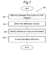
- a method 200 for identifying a difference between a first 3D model of an environment and a second 3D model of the environment is illustrated. The method is based on the prerequisite that the first and second 3D model each comprises a plurality of points or parts and that each point or part of the first and second model comprises geometrical information and texture information.
- the method comprises a step of matching 210 the first 3D model with the second 3D model.
- the matching is performed such that corresponding points or parts of the first and second 3D model are matched based on the geometrical information and/or the texture information.
- the first and the second model may have different accuracy, which may be taken into account in the matching.
- the matching is in one example a global matching. This means that the first and second models as a whole are matched using translation and/or rotation and/or a higher order model.
- the matching may for example involve using least square method(s).
- the matching involves performing bundle adjustments.
- bundle adjustment can be defined as the problem of simultaneously refining the 3D coordinates describing the scene geometry as well as the parameters of the relative motion and the optical characteristics of the camera(s) employed to acquire the images, according to an optimality criterion involving the corresponding image projections of all points.
- Bundle adjustments are known in the art and thus not described here any further.
- the matched points or parts of the first and second model are compared 220 to determine a relation between the first 3D model and the second 3D model. This is done by determining at least one difference value based on the geometrical information and the texture information of the first and second model.
- the comparing 220 comprises for each point or part of the first 3D model to search for a closest point in the second 3D model. The at least one difference is determined based on a found closest point in the second 3D model. Thus, a local search is performed for a closest point in the second 3D model and the difference value is determined based on the result of this search.
- a difference between the first and second model is identified if the at least one difference value exceeds a predetermined value.
- an uncertainty for the geometrical information is associated to each point or part of the respective 3D model and/or an uncertainty for the texture information is associated to each point or part of the respective model.
- the method then further comprises a step of identifying 230 a difference between the first and second models for each point or part based on the determined at least one difference value and based on the geometrical information uncertainty for the respective model and/or the texture information uncertainty for the respective model. Examples of how the geometrical information uncertainty and the texture information uncertainty can be determined have been described in this disclosure.
- the method further comprises an optional step of classifying 240 the identified difference.
- the classification is based on whether an identified difference is caused by natural variations or by other causes such as humans, natural disasters, etc.
- the 3D models or the measurements on which the models are based is associated to information related to the time of the year, daytime, resolution, from which source the measurement is originating, in which colours image are taken, etc., this information can be used for determining whether an identified difference is based on natural variations or not.
- measurements can be sorted out or kept according to the seasons at which they were taken.
- One example is areas which in winter usually are covered by snow and/or which have deciduous trees. In these areas both colour can change between the seasons, but also the height profile. If an area gets lot of snow in winter, but roads are kept free from snow during winter, the height profile in this area changes during seasons.
- the method further comprises an optional step of presenting 250 information related to the part or points of the models for which a difference has been identified.
- the presented information comprises in one example information identifying the point or part for which the difference has been identified and a presentation of the identified difference.
- the presented information is visualized in the first or second 3D model.
- a step of comparing a first and second 3D model comprises for each point or part of the first 3D model 301a searching for a closest point in the second 3D model 301b and to determine the at least one difference d based on a found closest point in the second 3D model.
- the search is in the illustrated example performed in a radius in relation to the point or part in the first model. In one example, the search is performed in two dimensions. In one example the search is performed in three dimensions. The search is performed within a search radius d max .
- the step of comparing a first and a second 3D model comprises for each point or part of the first 3D model searching for a closest point in the second 3D model to determine at least one first difference value d a for that point or part, for each point or part of the second 3D model searching for a closest point in the first 3D model to determine at least one second difference value d b for that point or part, and to determine the at least one difference value based on the at least one first difference value d a and the at least one second difference value d b .
- geometrical information of a first 2D model and/or a second 3D model 401 is defined by a mesh modelling the environment in three dimensions.
- the mesh comprises nodes 402 interconnected by edges 403 and having surfaces 404 boarded by the edges.
- Each node and/or edge and or surface is associated to a 3D coordinate in a geographical coordinate system.
- a plurality of the nodes and/or edges and/or surfaces of the mesh are associated to an attribute.
- the attribute comprises the texture information.
- the attribute comprises in one example also a texture information uncertainty and/or a geometrical information uncertainty.
- a geometrical information uncertainty and/or texture information uncertainty comprises a value for the uncertainty in at least two directions.
- the geometrical information uncertainty and/or texture information uncertainty comprises in one additional or alternative example at least one value related to a distance and/or at least one probability value.
- an arrangement 600 for identifying a difference between a first 3D model 101a of an environment and a second 3D model 101b of the environment is illustrated.
- the arrangement 600 comprises a memory 654 for having access to the first and second 3D model.
- the memory is arranged to temporarily store relevant parts of the first and second model.
- the arrangement comprises means for having access to the first and second 3D model.
- the first and second 3D model is stored in a database.
- the first and second 3D model are stored at one or more remote locations and the means for having access to the first and second 3D model are arranged to supply the first and second 3D model via a network to the arrangement.
- the first and second 3D model are supplied via wireless communication.
- first and second 3D model are supplied via wired communication.
- the access to the first and second model is in one example provided by means of an interface 656.
- the first and second 3D model each comprises a plurality of points or parts. Each point or part of the first and second models comprises geometrical information and texture information.
- the memory comprises the first and second 3D model.
- the memory 654 or means for having access to the first and second 3D model is arranged to store an uncertainty for the geometrical information, which uncertainty is associated to each point or part of the respective 3D model, and it is arranged to store an uncertainty for the texture information, which uncertainty is associated to each point or part of the respective model.
- the arrangement 600 further comprises a processing element 650.
- the processing element 650 is arranged to match corresponding points or parts of the first and second 3D models based on the geometrical information and/or the texture information. This is in one example performed in a matching element 651
- the processing element 650 is further arranged to compare the matched points or parts of the first and second model to determine at least one difference value based on the geometrical information and the texture information of the first and second model.
- the comparing is in one example performed in a comparing element 652.
- the processing element 650 is in one example arranged to identify a difference between the first and second model if the at least one difference value exceeds a predetermined value.
- the processing element 650 is arranged to identify a difference between the first and second models for each point or part based on the determined at least one difference value and based on the geometrical information uncertainty for the respective model and/or the texture information uncertainty for the respective model. This is in one example performed in a difference identifying element 653.
- the processing element 650 is formed as one or more processing units. In one example the processing element 650 is several processing units. In one example the processing units are located at remote locations and arranged to communicate with each other.
- processing element 650 is further arranged to classify an identified difference between the first and second model.
- the classification comprises determining whether the identified difference is caused by natural variations.
- the processing element 650 comprises in one example a computer program comprising a program code for executing the identifying of a difference between a first 3D model of an environment and a second 3D model of the environment.
- the arrangement 600 further comprises a presentation unit 655.
- the presentation unit is arranged to present information related to the part or points of the the first and/or second 3D model for which a difference has been identified.
- the presentation unit is a display.
- the presentation unit is a screen.
- the presentation unit is a printer.
- the presentation unit is a projector.
- the presentation unit is arranged to receive information from the processing element.
- a method 700 for identifying a difference between a 3D model of an environment and the environment as reproduced at another timing, wherein said reproduction of the environment comprises at least one 2D image, is illustrated.
- Each point or part of the 3D model comprises geometrical and texture information. The method comprises the following steps.
- corresponding points or parts of the 3D model and the at least one image are matched 706 based on the texture information in the 3D model and texture information in the at least one 2D image.
- the matching is in one example a global matching.
- one or a plurality of images which have been used for building the 3D model is used for matching the 2D image.
- texture information may be matched.
- the matching is performed using translation and/or rotation and/or a higher order model.
- the matching may for example involve using least square method.
- the matching involves performing bundle adjustments. Bundle adjustments are known in the art and thus not described here any further.
- the matching involves establishing point correspondence between the 3D model and the at least one 2D image.
- georeferencing information is used in the matching.
- a geometrical information uncertainty is associated to each point or part of the 3D model and/or a texture information uncertainty is associated to each point or part of the 3D model.
- the method comprises an optional step 708 of identifying a difference between the 3D model and the at least one 2D image based on the determined at least one difference value, and based on the geometrical information uncertainty and/or the texture information uncertainty. Examples of how the geometrical information uncertainty and the texture information uncertainty can be determined are described earlier in this disclosure.
- the method further comprises an optional step of presenting 709 information related to the part or points of the 3D model for which a difference has been identified.
- the arrangement 800 comprises a memory 864 or means for having access to the reproduction of the environment comprising at least one 2D image, and to the first 3D model, wherein each point or part of the first 3D model comprises geometrical and texture information.
- the memory 864 comprises the reproduction of the environment and the first 3D model.
- the arrangement comprises means for having access to the reproduction of the environment and the first 3D model.
- the reproduction of the environment and the first 3D model are stored in a database.
- the reproduction of the environment and the first 3D model are stored at one or more remote locations and the means for having access to the reproduction of the environment and the first 3D model are arranged to supply the reproduction of the environment and the first 3D model via a network to the arrangement.
- the reproduction of the environment and the first 3D model are supplied via wireless communication.
- the reproduction of the environment and the first 3D model are supplied via wired communication.
- the access to the first and second model is in one example provided by means of an interface 866.
- the arrangement 800 further comprises a processing element 860, arranged to match corresponding points or parts of the 3D model and the at least one image based on the texture information in the 3D model and texture information in the at least one 2D image.
- the matching is in one example performed in a matching element 861.
- the processing element is further arranged to determine at least one difference value for the texture information for each corresponding part or point of the first 3D model and the at least one 2D image. This is in one example performed in a difference value determining element 862.
- the processing element 860 is in one example arranged to identify a difference between the 3D model and the at least one 2D image if the at least one difference value for the texture information exceeds a predetermined value.
- the memory 864 or means for having access to the first and second 3D model is arranged to store a geometrical information uncertainty associated to each point or part of the 3D model and arranged to store a texture information associated to each point or part of the 3D model.
- the processing element 650 is arranged to identifying a difference between the first and second model for each point or part based on the determined at least one difference value and based on the geometrical information uncertainty and/or the texture information uncertainty. This is in one example performed in a difference identifying element 863.
- the processing element 860 comprises one or more processing units. In one example the processing element comprises several processing units. In one example the processing units are located at remote locations and arranged to communicate with each other.
- the arrangement further comprises a presentation unit 865.
- the presentation unit 865 is arranged to present information related to the part or points of the model and/or image for which a difference has been identified.
- the presentation unit is a display.
- the presentation unit is a screen.
- the presentation unit is a printer.
- the presentation unit is a projector.
- the presentation unit is arranged to receive information from the processing element.
Landscapes
- Engineering & Computer Science (AREA)
- Physics & Mathematics (AREA)
- Theoretical Computer Science (AREA)
- General Physics & Mathematics (AREA)
- Computer Vision & Pattern Recognition (AREA)
- Multimedia (AREA)
- Software Systems (AREA)
- Remote Sensing (AREA)
- Evolutionary Computation (AREA)
- Artificial Intelligence (AREA)
- Geometry (AREA)
- Databases & Information Systems (AREA)
- Health & Medical Sciences (AREA)
- Medical Informatics (AREA)
- General Health & Medical Sciences (AREA)
- Astronomy & Astrophysics (AREA)
- Computing Systems (AREA)
- Data Mining & Analysis (AREA)
- Computer Graphics (AREA)
- General Engineering & Computer Science (AREA)
- Bioinformatics & Computational Biology (AREA)
- Life Sciences & Earth Sciences (AREA)
- Evolutionary Biology (AREA)
- Bioinformatics & Cheminformatics (AREA)
- Processing Or Creating Images (AREA)
- Image Generation (AREA)
- Image Processing (AREA)
- Image Analysis (AREA)
Abstract
Description
- The present disclosure relates to a method and arrangement for identifying a difference between a first 3D model of an environment and a second 3D model of the environment. In particular, the present disclosure relates to identifying a difference, wherein the first and second 3D model each comprise a plurality of points or parts, and wherein each point or part of the first and second model comprises geometrical information and texture information
- The present disclosure also relates to a method and arrangement for identifying a difference between a 3D model of an environment and the environment as reproduced at another timing. In particular, the present disclosure relates to identifying a difference, wherein said reproduction of the environment comprising at least one 2D image, and wherein each point or part of the first 3D model comprises geometrical and texture information
- A fast growing market both in civilian and military business is geographical information systems. Knowledge about geographical conditions forms a fundamental decision support to companies, authorities and in the military. The geographical information can comprise digital maps having superposed information layers such as infrastructure, terrain type and different types of objects. This way of providing digital maps is time consuming and comprises forming two dimensional maps comprising capturing images of the terrain from an aircraft and post-processing of the captured images. It is an even more time consuming process to form three dimensional maps from captured images or range data sets of the terrain/infrastructure.
-
WO 2009/003529 relates to another type of geographical information system. It relates to an arrangement and a method for providing a three dimensional map representation of an area. The arrangement comprises a processing unit arranged to, for a plurality of time recorded, overlapping images of the area to be stereo processed, associate navigation states so that each pixel of each time recorded image is correlated to a corresponding navigation state and to perform the stereo processing based on the associated navigation states that all pixels in the map representation are specified in three geographical dimensions. - It is desirable to detect changes in the environment. These changes can be due natural variations like flooding, earthquakes, moving glaciers, falling rocks, erosions, or the like. They can also be due to growing plants or trees, due to different seeds on fields or the like. They can also be due to human made interactions like construction working (for example for building infrastructure, buildings, etc...), removing or destroying of constructions (for example, due to war, due to fire, due to forces of nature, due to dismantling or demolishing of buildings, constructions for other purposes, etc.).
- For detecting these changes, a common way is to compare maps or images. This is often done in a manual way to find differences between them. This is a time-consuming task.
- One object of the present invention is to improve the process of identifying differences in an environment.
- This object is achieved by method for identifying a difference between a first 3D model of an environment and at least a second 3D model of the environment. The first and second 3D model each comprises a plurality of points or parts, wherein each point or part of the first and second model comprises geometrical information and texture information. Corresponding points or parts of the first and second 3D model are matched based on the geometrical information and/or the texture information. The matched points or parts of the first and second model are compared to determine at least one difference value based on the geometrical information and the texture information of the first and second model.
- This method can be performed in a highly automated way, thus reducing the amount of time and/or workload an operator has to spend for identifying differences.
- In one example, an uncertainty for the geometrical information is associated to each point or part of the respective 3D model and an uncertainty for the texture information is associated to each point or part of the respective model. A difference between the first and second model is identified for each point or part based on the determined at least one difference value and based on the geometrical information uncertainty for the respective model and/or the texture information uncertainty for the respective model.
- This has the advantages that one can differ between differences which originate from measurement uncertainties and differences which originate from actual changes in the environment.
- In one example the geometrical information uncertainty at each point or part is based on a local geometry of the 3D model at that point or part.
- By doing so a refined method is achieved for differing between differences which originate from measurement uncertainties and differences which originate from actual changes in the environment.
- In one example, the geometrical information uncertainty and/or texture information uncertainty is based on a number of measurements on which the respective model is based for each point or part of the respective 3D models.
- In one example, the geometrical information uncertainty and/or texture information uncertainty is based on a spread in measurements on which the respective model is based for each point or part of the respective 3D models.
- In one example, the geometrical information uncertainty comprises a value for the uncertainty in at least two directions and/or at least one value related to a distance and/or at least one probability value.
- All these examples present methods, which in a refined way can differ between differences which originate from measurement uncertainties and differences which originate from actual changes in the environment.
- In one example the texture information comprises colour information and/or grey scale information.
- By doing so, even differences which do not originate from a changed geometrical shape in the environment can be identified.
- In one example the texture information uncertainty comprises an uncertainty related to the colour and/or greyscale and/or a frequency value and/or a grey scale value and/or a percentage value.
- This allows differing between differences which originate from imprecise equipment, for example imprecise camera sensors, and differences which actually originate from differences in the environment.
- In one example comparing the first and second 3D model comprises, for each point or part of the first 3D model, searching for a closest point in the second 3D model and to determine the at least one difference based on a found closest point in the second 3D model.
- This will result in that differences which originate from shifts in the models will not falsely be identified as differences in the environment.
- In one example comparing the first and second 3D model further comprises, for each point or part of the first 3D model, searching for a closest point in the second 3D model to determine at least one first difference value for that point or part. It also comprises, for each point or part of the second 3D model, searching for a closest point in the first 3D model to determine at least one second difference value for that point or part. The at least one difference value is determined based on the at least one first difference value and the at least one second difference value.
- By doing so more differences in the environment can be identified. For example, both additional constructions/objects and removed constructions/objects will be identified.
- In one example the geometrical information of the first and the second 3D model is defined by a mesh modelling the environment in three dimensions, said mesh comprising nodes interconnected by edges and having surfaces boarded by the edges.
- This allows for a practical implementation of the method.
- In one example a plurality of the nodes and/or edges and/or surfaces of the mesh are associated to an attribute. The attribute comprises the texture information and/or the texture information uncertainty and/or the geometrical information uncertainty.
- This allows for a practical implementation of the method as well.
- In one example the geometrical information comprises coordinate information in a three dimensional coordinate system, such as a geo-referenced coordinate system.
- In this way identified differences in the environment can be connected to specific positions.
- In one example identified differences are classified, which comprises determining whether the identified difference is caused by natural variations.
- This allows differing between differences caused by human interaction actions and differences caused by nature.
- In one example the determination whether the identified difference is caused by natural variations is based on attribute information associated to the respective 3D model or measurements on which the respective model is based. The attribute information comprises at least one of the following: time of the year, daytime, resolution, from which source or sources the 3D model or measurement is originating, in which colours images are taken.
- By doing this the classification can be automated.
- In one example, the information related to the part or points of the models for which a difference has been identified is presented.
- In one example the presented information comprises information identifying the point or part for which the difference has been identified and a presentation of the identified difference.
- In one example the presented information is visualized in the first and/or second 3D model.
- The above examples facilitate for a user of the method to draw conclusions from the identified differences.
- The object is also achieved by a computer program, which comprises a program code for executing the method for identifying a difference between a first 3D model of an environment and a second 3D model of the environment.
- The object is also achieved by a computer program product, which comprises a program code stored on a computer readable media for executing the method for identifying a difference between a first 3D model of an environment and a second 3D model of the environment.
- The object is also achieved by an arrangement for identifying a difference between a first 3D model of an environment and a second 3D model of the environment. The arrangement comprises a memory or means for having access to the first and second 3D model. The first and second 3D model each comprises a plurality of points or parts, wherein each point or part of the first and second model comprises geometrical information and texture information. The arrangement also comprises a processing element. The processing element is arranged to match corresponding points or parts of the first and second 3D model based on the geometrical information and/or the texture information It is also arranged to compare the matched points or parts of the first and second model to determine at least one difference value based on the geometrical information and the texture information of the first and second model.
- The arrangement performs the process of identifying differences in an environment in a highly automated way, thus reducing the amount of time and/or workload an operator has to spend for identifying differences.
- In one example, the memory or means for having access to the first and second 3D model are arranged to store an uncertainty for the geometrical information. The geometrical information uncertainty is associated to each point or part of the respective 3D model. The memory or means for having access to the first and second 3D model are also arranged to store an uncertainty for the texture information. The texture information uncertainty is associated to each point or part of the respective model. The processing element is further arranged to identify a difference between the first and second model for each point or part based on the determined at least one difference value and based on the geometrical information uncertainty for the respective model and/or the texture information uncertainty for the respective 3D model.
- This has the advantages that one can differ between differences which originate from measurement uncertainties and differences which originate from actual changes in the environment.
- In one example the processing element is further arranged to classify an identified difference between the first and second model. This comprises to determine whether the identified difference is caused by natural variations.
- This allows differing between differences caused by human interaction actions and differences caused by nature.
- In one example the arrangement comprises a presentation unit. The presentation unit is arranged to present information related to the part or points of the models for which a difference has been identified.
- The object is also achieved by a method for identifying a difference between a 3D model of an environment and the environment as reproduced at another timing. The reproduction of the environment comprises at least one 2D image, wherein each point or part of the 3D model comprises geometrical and texture information. Corresponding points or parts of the 3D model and the at least one 2D image are matched based on the texture information in the 3D model and texture information in the at least one 2D image. At least one difference value for the texture information is determined for each corresponding part or point of the first 3D model and the at least one 2D image.
- This has the advantage that one does not need to have two 3D models of the environment. This allows determining difference values, for example, even for moments of time where no 3D model is available.
- In one example, a geometrical information uncertainty is associated to each point or part of the 3D model, and/or a texture information uncertainty is associated to each point or part of the 3D model. A difference between the 3D model and the at least one 2D image is identified based on the determined at least one difference value, and based on the geometrical information uncertainty and/or the texture information uncertainty.
- This allows better identifying differences in the environment compared to a moment of time where no 3D model is/was available. It further allows to differ between differences which originate from measurement uncertainties and differences which originate from actual changes in the environment.
- In one example, information related to the part or points of the 3D model for which a difference has been identified is presented.
- This facilitates for a user of the method to draw conclusions from the identified differences.
- The object is also achieved by an arrangement for identifying a difference between a 3D model of an environment and the environment as reproduced at another timing. The arrangement comprises a memory or means for having access to the reproduction of the environment and to the first 3D model. The reproduction of the environment comprises at least one 2D image. Each point or part of the 3D model comprises geometrical and texture information. The arrangement also comprises a processing element. The processing element is arranged to match corresponding points or parts of the 3D model and the at least one 2D image reproducing the environment based on the texture information in the 3D model and texture information in the at least one 2D image. It is also arranged to determine at least one difference value for the texture information for each corresponding part or point of the first 3D model and the at least one 2D image.
- The arrangement performs the process of identifying differences in an environment in a highly automated way, thus reducing the amount of time and/or workload an operator has to spend for identifying differences. The arrangement further has the advantage that one does not need to have two 3D models of the environment. This allows determining difference values, for example, even for moments of time where no 3D model is available.
- In one example the memory or means for having access to the 3D model is further arranged to store a geometrical information uncertainty associated to each point or part of the 3D model and to store a texture information associated to each point or part of the 3D model. The processing element is further arranged to identifying a difference between the 3D model and the 2D image for each point or part based on the determined at least one difference value and based on the geometrical information uncertainty and/or the texture information uncertainty.
- This allows better identifying differences in the environment compared to a moment of time where no 3D model is/was available. It further allows to differ between differences which originate from measurement uncertainties and differences which originate from actual changes in the environment.
- In one example the arrangement further comprises a presentation unit arranged to present information related to the part or points of the model and/or image for which a difference has been identified.
- This facilitates for a user of the arrangement to draw conclusions from the identified differences.
- The object is also achieved by a computer program comprising a program code for executing the method for identifying a difference between a 3D model of an environment and the environment as reproduced at another timing.
- The object is also achieved by a computer program product comprising a program code stored on a computer readable media for executing the method for identifying a difference between a 3D model of an environment and the environment as reproduced at another timing.
-
-
Figure 1 shows a side view of an example of a first 3D model and a second 3D model. -
Figure 2 is flow chart illustrating one example of a method for identifying a difference between a first 3D model of an environment and a second 3D model of the environment. -
Figures 3a-3c illustrates examples for comparing a first and second 3D model for each point or pa rt. -
Fig 4 illustrates schematically one example of a 3D model. -
Fig 5 illustrates schematically an example of an uncertainty associated to points or parts of a 3D model. -
Figure 6 is a block scheme illustrating an example of an arrangement for identifying a difference between a first 3D model of an environment and a second 3D model of the environment. -
Figure 7 is flow chart illustrating one example of a method for identifying a difference between a first 3D model of an environment and the environment as reproduced at another timing. -
Figure 8 is a block scheme illustrating an example of an arrangement for identifying a difference between a first 3D model of an environment and the environment as reproduced at another timing. - In
Figure 1 , a difference between afirst 3D model 101a of an environment and asecond 3D model 101b of the environment is schematically illustrated. The first 3D model is illustrated with a full line. The second 3D model is illustrated with a broken line. Thefirst 3D model 101a comprises a plurality of first points orparts 117a. Each first point orpart 117a comprises geometrical information and texture information. Thesecond 3D model 101b comprises a plurality of second points orparts 117b. Each second point orpart 117b comprises geometrical information and texture information. Only a few of the first points orparts 117a and second points orparts 117b are shown in the figure in order to make the figure clear. - The geometrical information comprises coordinate information in a three dimensional coordinate system. In one example, the coordinate system is a geo-referenced coordinate system. The texture information comprises in one example colour information and/or grey scale information.
- In one example the first 3D model and/ or the second 3D model is formed based on 2D images, distance measurements such as LIDAR etc. When basing the 3D model on 2D images, the 3D models may have been provided by establishing stereo matching correspondence for stereo pairs based on different combinations of two 2D images and building the 3D model based on the established stereo matching correspondence for the stereo pairs. Details related to building 3D models from 2D images are known in the art and is left out from this description.
- The first 3D model and/or the second 3D model may be represented in numerous ways. In one example, at least one of the 3D models is represented as a textured mesh. In one example, at least one of the 3D models is represented as a point cloud. In one example, at least one of the 3D models is represented as a voxel.
- In one example, an uncertainty for the geometrical information is associated to each point or part of the respective 3D model. Thus the first points or
parts 117a of thefirst 3D model 101a are each associated to a geometrical information uncertainty. Further, the second points orparts 117b of thesecond 3D model 101b are each associated to a geometrical information uncertainty. In the same way, a texture information uncertainty is associated to each point or part of the respective model. - The geometrical information uncertainty and the texture information uncertainty can be formed by uncertainties related to one or a plurality of factors. Thus, different types of geometrical information uncertainties and texture information uncertainties can be accounted for. Some examples are given below. In one example geometrical information uncertainty and/or the texture information uncertainty for each point or part is based on the uncertainties of different types. The geometrical information uncertainty and/or the texture information uncertainty for each point or part can be a weighted sum of uncertainties of different types.
- Some types of geometrical information uncertainties and/or texture information uncertainties are isolated to individual points or
parts - The geometrical information uncertainty and/or the texture information uncertainty may be a value for the uncertainty in one, two or three directions. The value may be related to a distance. The value may be a probability value. In one example, the geometrical information uncertainty and/or texture information uncertainty is represented as a hypothesis.
- In one example, the geometrical information uncertainty at each point or part is based on a local geometry of the 3D model at that point or part.
- In one example, the geometrical information uncertainty and/or texture information uncertainty is based on a number of measurements on which the respective 3D model is based for each point or part of the respective 3D models.
- In one example, the geometrical information uncertainty and/or texture information uncertainty is based on a spread in measurements on which the respective model is based for each point or part of the respective 3D models.
- In one example, the texture information uncertainty comprises an uncertainty related to the colour and/or greyscale. In one example, the texture information uncertainty comprises an uncertainty related to a frequency value. In one example, the texture information uncertainty relates to a grey scale value. In one example, the texture information uncertainty relates to a percentage value.
- As is understood from the above, one, some or all of the examples of geometrical information uncertainties and texture information uncertainties described herein can be selected, along with other, not disclosed types of uncertainties to form a geometrical information uncertainty and to form a texture information uncertainty.
- In
Figure 2 , amethod 200 for identifying a difference between a first 3D model of an environment and a second 3D model of the environment is illustrated. The method is based on the prerequisite that the first and second 3D model each comprises a plurality of points or parts and that each point or part of the first and second model comprises geometrical information and texture information. - The method comprises a step of matching 210 the first 3D model with the second 3D model. The matching is performed such that corresponding points or parts of the first and second 3D model are matched based on the geometrical information and/or the texture information. The first and the second model may have different accuracy, which may be taken into account in the matching.
- There are many ways known in the art for achieving matching of data in two models. The matching is in one example a global matching. This means that the first and second models as a whole are matched using translation and/or rotation and/or a higher order model. The matching may for example involve using least square method(s).
- In one example, wherein the models are formed based on images, the matching involves performing bundle adjustments. Given a set of images depicting a number of 3D points from different viewpoints, bundle adjustment can be defined as the problem of simultaneously refining the 3D coordinates describing the scene geometry as well as the parameters of the relative motion and the optical characteristics of the camera(s) employed to acquire the images, according to an optimality criterion involving the corresponding image projections of all points. Bundle adjustments are known in the art and thus not described here any further.
- In a next step, the matched points or parts of the first and second model are compared 220 to determine a relation between the first 3D model and the second 3D model. This is done by determining at least one difference value based on the geometrical information and the texture information of the first and second model. In one example, the comparing 220 comprises for each point or part of the first 3D model to search for a closest point in the second 3D model. The at least one difference is determined based on a found closest point in the second 3D model. Thus, a local search is performed for a closest point in the second 3D model and the difference value is determined based on the result of this search. In one example, a difference between the first and second model is identified if the at least one difference value exceeds a predetermined value.
- In one example, an uncertainty for the geometrical information is associated to each point or part of the respective 3D model and/or an uncertainty for the texture information is associated to each point or part of the respective model. In one optional step, the method then further comprises a step of identifying 230 a difference between the first and second models for each point or part based on the determined at least one difference value and based on the geometrical information uncertainty for the respective model and/or the texture information uncertainty for the respective model. Examples of how the geometrical information uncertainty and the texture information uncertainty can be determined have been described in this disclosure.
- The method further comprises an optional step of classifying 240 the identified difference. In one example the classification is based on whether an identified difference is caused by natural variations or by other causes such as humans, natural disasters, etc.
- If the 3D models or the measurements on which the models are based is associated to information related to the time of the year, daytime, resolution, from which source the measurement is originating, in which colours image are taken, etc., this information can be used for determining whether an identified difference is based on natural variations or not. When building a 3D model of an area where the seasons have great impact on the appearance of the area, measurements can be sorted out or kept according to the seasons at which they were taken. One example is areas which in winter usually are covered by snow and/or which have deciduous trees. In these areas both colour can change between the seasons, but also the height profile. If an area gets lot of snow in winter, but roads are kept free from snow during winter, the height profile in this area changes during seasons. In that case it is advantageous to choose measurement from only one season, for example summer in building the 3D models. Also sorting out measurements according to any other predetermined requirement might be helpful, if that requirement has an impact on the appearance of the environment or on the possibility to built accurate 3D models.
- The method further comprises an optional step of presenting 250 information related to the part or points of the models for which a difference has been identified. The presented information comprises in one example information identifying the point or part for which the difference has been identified and a presentation of the identified difference. In one example, the presented information is visualized in the first or second 3D model.
- In
figures 3a-3c , a step of comparing a first and second 3D model comprises for each point or part of thefirst 3D model 301a searching for a closest point in thesecond 3D model 301b and to determine the at least one difference d based on a found closest point in the second 3D model. The search is in the illustrated example performed in a radius in relation to the point or part in the first model. In one example, the search is performed in two dimensions. In one example the search is performed in three dimensions. The search is performed within a search radius dmax. - In
figures 3b-c the step of comparing a first and a second 3D model comprises for each point or part of the first 3D model searching for a closest point in the second 3D model to determine at least one first difference value da for that point or part, for each point or part of the second 3D model searching for a closest point in the first 3D model to determine at least one second difference value db for that point or part, and to determine the at least one difference value based on the at least one first difference value da and the at least one second difference value db. - Using the procedure as described in relation to
figures 3a-3c ensures that objects present in one of the 3D models but not the other are found. - In the example of
Figure 4 , geometrical information of a first 2D model and/or asecond 3D model 401 is defined by a mesh modelling the environment in three dimensions. The mesh comprisesnodes 402 interconnected byedges 403 and havingsurfaces 404 boarded by the edges. Each node and/or edge and or surface is associated to a 3D coordinate in a geographical coordinate system. In one example, a plurality of the nodes and/or edges and/or surfaces of the mesh are associated to an attribute. The attribute comprises the texture information. The attribute comprises in one example also a texture information uncertainty and/or a geometrical information uncertainty. - In
figure 5 , a geometrical information uncertainty and/or texture information uncertainty comprises a value for the uncertainty in at least two directions. The geometrical information uncertainty and/or texture information uncertainty comprises in one additional or alternative example at least one value related to a distance and/or at least one probability value. - In
figure 6 , anarrangement 600 for identifying a difference between afirst 3D model 101a of an environment and asecond 3D model 101b of the environment is illustrated. Thearrangement 600 comprises amemory 654 for having access to the first and second 3D model. In one example, the memory is arranged to temporarily store relevant parts of the first and second model. In one example the arrangement comprises means for having access to the first and second 3D model. In one example the first and second 3D model is stored in a database. In one example the first and second 3D model are stored at one or more remote locations and the means for having access to the first and second 3D model are arranged to supply the first and second 3D model via a network to the arrangement. In one example the first and second 3D model are supplied via wireless communication. In one example the first and second 3D model are supplied via wired communication. The access to the first and second model is in one example provided by means of aninterface 656. The first and second 3D model each comprises a plurality of points or parts. Each point or part of the first and second models comprises geometrical information and texture information. In one example the memory comprises the first and second 3D model. - In one example, the
memory 654 or means for having access to the first and second 3D model is arranged to store an uncertainty for the geometrical information, which uncertainty is associated to each point or part of the respective 3D model, and it is arranged to store an uncertainty for the texture information, which uncertainty is associated to each point or part of the respective model. - The
arrangement 600 further comprises aprocessing element 650. Theprocessing element 650 is arranged to match corresponding points or parts of the first and second 3D models based on the geometrical information and/or the texture information. This is in one example performed in amatching element 651 Theprocessing element 650 is further arranged to compare the matched points or parts of the first and second model to determine at least one difference value based on the geometrical information and the texture information of the first and second model. The comparing is in one example performed in a comparingelement 652. Theprocessing element 650 is in one example arranged to identify a difference between the first and second model if the at least one difference value exceeds a predetermined value. - In one example, the
processing element 650 is arranged to identify a difference between the first and second models for each point or part based on the determined at least one difference value and based on the geometrical information uncertainty for the respective model and/or the texture information uncertainty for the respective model. This is in one example performed in adifference identifying element 653. - In one example the
processing element 650 is formed as one or more processing units. In one example theprocessing element 650 is several processing units. In one example the processing units are located at remote locations and arranged to communicate with each other. - In one example the
processing element 650 is further arranged to classify an identified difference between the first and second model. The classification comprises determining whether the identified difference is caused by natural variations. - The
processing element 650 comprises in one example a computer program comprising a program code for executing the identifying of a difference between a first 3D model of an environment and a second 3D model of the environment. - In one example the
arrangement 600 further comprises apresentation unit 655. The presentation unit is arranged to present information related to the part or points of the the first and/or second 3D model for which a difference has been identified. In one example the presentation unit is a display. In one example the presentation unit is a screen. In one example the presentation unit is a printer. In one example the presentation unit is a projector. In one example the presentation unit is arranged to receive information from the processing element. - In
figure 7 , amethod 700 for identifying a difference between a 3D model of an environment and the environment as reproduced at another timing, wherein said reproduction of the environment comprises at least one 2D image, is illustrated. Each point or part of the 3D model comprises geometrical and texture information. The method comprises the following steps. - In a first step, corresponding points or parts of the 3D model and the at least one image are matched 706 based on the texture information in the 3D model and texture information in the at least one 2D image.
- There are many ways known in the art for achieving matching a 3D model with 2D images. The matching is in one example a global matching. In one example, one or a plurality of images which have been used for building the 3D model is used for matching the 2D image. Then, texture information may be matched. For example, the matching is performed using translation and/or rotation and/or a higher order model. The matching may for example involve using least square method.
- In one example, wherein the 3D model is formed based on images, the matching involves performing bundle adjustments. Bundle adjustments are known in the art and thus not described here any further. In one example the matching involves establishing point correspondence between the 3D model and the at least one 2D image.
- In one additional or complementing example, georeferencing information is used in the matching.
- In a next step, at least one difference value for the texture information for each corresponding part or point of the first 3D model and the at least one 2D image is determined.
In one example, a geometrical information uncertainty is associated to each point or part of the 3D model and/or a texture information uncertainty is associated to each point or part of the 3D model. In this example, the method comprises anoptional step 708 of identifying a difference between the 3D model and the at least one 2D image based on the determined at least one difference value, and based on the geometrical information uncertainty and/or the texture information uncertainty. Examples of how the geometrical information uncertainty and the texture information uncertainty can be determined are described earlier in this disclosure. - The method further comprises an optional step of presenting 709 information related to the part or points of the 3D model for which a difference has been identified.
- In
figure 8 , an example of anarrangement 800 for identifying a difference between a first 3D model of an environment and the environment as reproduced at another timing is described. Thearrangement 800 comprises amemory 864 or means for having access to the reproduction of the environment comprising at least one 2D image, and to the first 3D model, wherein each point or part of the first 3D model comprises geometrical and texture information. In one example thememory 864 comprises the reproduction of the environment and the first 3D model. In one example the arrangement comprises means for having access to the reproduction of the environment and the first 3D model. In one example the reproduction of the environment and the first 3D model are stored in a database. In one example the reproduction of the environment and the first 3D model are stored at one or more remote locations and the means for having access to the reproduction of the environment and the first 3D model are arranged to supply the reproduction of the environment and the first 3D model via a network to the arrangement. In one example the reproduction of the environment and the first 3D model are supplied via wireless communication. In one example the reproduction of the environment and the first 3D model are supplied via wired communication. The access to the first and second model is in one example provided by means of aninterface 866. - The
arrangement 800 further comprises aprocessing element 860, arranged to match corresponding points or parts of the 3D model and the at least one image based on the texture information in the 3D model and texture information in the at least one 2D image. The matching is in one example performed in amatching element 861. The processing element is further arranged to determine at least one difference value for the texture information for each corresponding part or point of the first 3D model and the at least one 2D image. This is in one example performed in a differencevalue determining element 862. Theprocessing element 860 is in one example arranged to identify a difference between the 3D model and the at least one 2D image if the at least one difference value for the texture information exceeds a predetermined value. In one example, thememory 864 or means for having access to the first and second 3D model is arranged to store a geometrical information uncertainty associated to each point or part of the 3D model and arranged to store a texture information associated to each point or part of the 3D model. - In one example, the
processing element 650 is arranged to identifying a difference between the first and second model for each point or part based on the determined at least one difference value and based on the geometrical information uncertainty and/or the texture information uncertainty. This is in one example performed in adifference identifying element 863. - In one example the
processing element 860 comprises one or more processing units. In one example the processing element comprises several processing units. In one example the processing units are located at remote locations and arranged to communicate with each other. - In one example the arrangement further comprises a
presentation unit 865. Thepresentation unit 865 is arranged to present information related to the part or points of the model and/or image for which a difference has been identified. In one example the presentation unit is a display. In one example the presentation unit is a screen. In one example the presentation unit is a printer. In one example the presentation unit is a projector. In one example the presentation unit is arranged to receive information from the processing element.
Claims (15)
- A method (200) for identifying a difference between a first 3D model (101a) of an environment and at least a second 3D model (101b) of the environment, wherein the first and second 3D model each comprise a plurality of points or parts, wherein each point or part of the first and second model comprises geometrical information and texture information, the method comprising the steps of:matching (210) corresponding points or parts of the first and second 3D model based on the geometrical information and/or the texture information, andcomparing (220) the matched points or parts of the first and second model to determine at least one difference value based on the geometrical information and the texture information of the first and second model.
- A method according to claim 1, wherein an uncertainty for the geometrical information is associated to each point or part of the respective 3D model and/or wherein an uncertainty for the texture information is associated to each point or part of the respective model, further comprising a step of identifying (230) a difference between the first and second model for each point or part based on the determined at least one difference value and based on the geometrical information uncertainty for the respective model and/or the texture information uncertainty for the respective model.
- Method according to claim 2, wherein the geometrical information uncertainty at each point or part is based on a local geometry of the 3D model at that point or part.
- A method according to any of the claims 2 to 3, wherein the geometrical information uncertainty comprises a value for the uncertainty in at least two directions and/or at least one value related to a distance and/or at least one probability value.
- A method according to any of the preceding claims, wherein the texture information comprises colour information and/or grey scale information
- A method according to any of the preceding claims, wherein the step of comparing the first and second 3D model further comprises
for each point or part of the first 3D model searching for a closest point in the second 3D model to determine at least one first difference value for that point or part
for each point or part of the second 3D model searching for a closest point in the first 3D model to determine at least one second difference value for that point or part, and to determine the at least one difference value based on the at least one first difference value and the at least one second difference value. - A method according to any of the preceding claims, further comprising a step of classifying (240) an identified difference, which comprises determining whether the identified difference is caused by natural variations.
- A method according to claim 7, wherein the determination whether the identified difference is caused by natural variations is based on attribute information associated to the respective 3D model or measurements on which the respective model is based, wherein the attribute information comprises at least one of the following: time of the year, daytime, resolution, from which source the 3D model or measurement is originating, in which colours images are taken.
- Computer program comprising a program code for executing the method for identifying a difference between a first 3D model of an environment and a second 3D model of the environment according to any of the preceding claims.
- Computer program product comprising a program code stored on a computer readable media for executing the method for identifying a difference between a first 3D model of an environment and a second 3D model of the environment according to any of the claims 1-18.
- An arrangement (600) for identifying a difference between a first 3D model (101a) of an environment and a second 3D model (101b) of the environment, the arrangement comprising:- a memory (654) or means for having access to the first and second 3D model, wherein the first and second 3D model each comprise a plurality of points or parts, wherein each point or part of the first and second model comprises geometrical information and texture information; and- a processing element (650) arranged to match corresponding points or parts of the first and second 3D model based on the geometrical information and/or the texture information, and to compare the matched points or parts of the first and second model to determine at least one difference value based on the geometrical information and the texture information of the first and second model.
- A method (700) for identifying a difference between a 3D model of an environment and the environment as reproduced at another timing, said reproduction of the environment comprising at least one 2D image, wherein each point or part of the 3D model comprises geometrical and texture information , the method comprising the steps of:matching (706) corresponding points or parts of the 3D model and the at least one 2D image based on the texture information in the 3D model and texture information in the at least one 2D image, anddetermining (707) at least one difference value for the texture information for each corresponding part or point of the first 3D model and the at least one 2D image.
- An arrangement (800) for identifying a difference between a 3D model of an environment and the environment as reproduced at another timing, the arrangement comprising:- a memory (864) or means for having access to the reproduction of the environment, which comprises at least one 2D image , and to the 3D model, wherein each point or part of the 3D model comprises geometrical and texture information; and- a processing element (860), arranged to match corresponding points or parts of the 3D model and the at least one 2D image reproducing the environment based on the texture information in the 3D model and texture information in the at least one 2D image, and to determine at least one difference value for the texture information for each corresponding part or point of the 3D model and the at least one 2D image.
- Computer program comprising a program code for executing the method for identifying a difference between a 3D model of an environment and the environment as reproduced at another timing, according to claim 12.
- Computer program product comprising a program code stored on a computer readable media for executing the method for identifying a difference between a 3D model of an environment and the environment as reproduced at another timing, according to claim 12.
Priority Applications (2)
| Application Number | Priority Date | Filing Date | Title |
|---|---|---|---|
| PL14165561T PL2911090T3 (en) | 2014-02-24 | 2014-04-23 | A method and arrangement for identifying a difference between a first 3D model of an environment and a second 3D model of the environment |
| EP18208356.8A EP3477546A1 (en) | 2014-02-24 | 2014-04-23 | A method and arrangement for identifying a difference between a first 3d model of an environment and a second 3d model of the environment |
Applications Claiming Priority (1)
| Application Number | Priority Date | Filing Date | Title |
|---|---|---|---|
| US14/188,314 US9460520B2 (en) | 2014-02-24 | 2014-02-24 | Method and arrangement for identifying a difference between a first 3D model of an environment and a second 3D model of the environment |
Related Child Applications (2)
| Application Number | Title | Priority Date | Filing Date |
|---|---|---|---|
| EP18208356.8A Division EP3477546A1 (en) | 2014-02-24 | 2014-04-23 | A method and arrangement for identifying a difference between a first 3d model of an environment and a second 3d model of the environment |
| EP18208356.8A Previously-Filed-Application EP3477546A1 (en) | 2014-02-24 | 2014-04-23 | A method and arrangement for identifying a difference between a first 3d model of an environment and a second 3d model of the environment |
Publications (2)
| Publication Number | Publication Date |
|---|---|
| EP2911090A1 true EP2911090A1 (en) | 2015-08-26 |
| EP2911090B1 EP2911090B1 (en) | 2018-11-28 |
Family
ID=50846758
Family Applications (2)
| Application Number | Title | Priority Date | Filing Date |
|---|---|---|---|
| EP14165561.3A Active EP2911090B1 (en) | 2014-02-24 | 2014-04-23 | A method and arrangement for identifying a difference between a first 3D model of an environment and a second 3D model of the environment |
| EP18208356.8A Pending EP3477546A1 (en) | 2014-02-24 | 2014-04-23 | A method and arrangement for identifying a difference between a first 3d model of an environment and a second 3d model of the environment |
Family Applications After (1)
| Application Number | Title | Priority Date | Filing Date |
|---|---|---|---|
| EP18208356.8A Pending EP3477546A1 (en) | 2014-02-24 | 2014-04-23 | A method and arrangement for identifying a difference between a first 3d model of an environment and a second 3d model of the environment |
Country Status (5)
| Country | Link |
|---|---|
| US (2) | US9460520B2 (en) |
| EP (2) | EP2911090B1 (en) |
| ES (1) | ES2712202T3 (en) |
| PL (1) | PL2911090T3 (en) |
| TR (1) | TR201901067T4 (en) |
Cited By (2)
| Publication number | Priority date | Publication date | Assignee | Title |
|---|---|---|---|---|
| CN109871761A (en) * | 2019-01-16 | 2019-06-11 | 中德(珠海)人工智能研究院有限公司 | A kind of identifying system of threedimensional model |
| EP3936816A4 (en) * | 2019-03-05 | 2022-05-04 | Panasonic Intellectual Property Management Co., Ltd. | MOVEMENT DETECTION METHOD, PHOTOGRAPHY INSTRUCTION METHOD, MOVEMENT DETECTION DEVICE AND PHOTOGRAPHY INSTRUCTION DEVICE |
Families Citing this family (8)
| Publication number | Priority date | Publication date | Assignee | Title |
|---|---|---|---|---|
| US9460520B2 (en) | 2014-02-24 | 2016-10-04 | Vricon Systems Ab | Method and arrangement for identifying a difference between a first 3D model of an environment and a second 3D model of the environment |
| US10489971B2 (en) * | 2015-06-17 | 2019-11-26 | Rosemount Aerospace Inc. | System and method for processing captured images for moving platform navigation |
| US10964098B1 (en) * | 2019-03-05 | 2021-03-30 | Facebook Technologies, Llc | Inverse path tracing for material and lighting estimation |
| CN110599594B (en) * | 2019-07-29 | 2021-07-20 | 成都理工大学 | A method for 3D modeling of petrophysical structure |
| CN111161252B (en) * | 2019-12-31 | 2022-03-25 | 山东大学 | Rock mass structure detection and dangerous stone detection system and method |
| EP4036859A1 (en) * | 2021-01-27 | 2022-08-03 | Maxar International Sweden AB | A system and method for providing improved geocoded reference data to a 3d map representation |
| GB2604927B (en) * | 2021-03-19 | 2023-12-20 | Imperial College Innovations Ltd | Modelling an environment using image data |
| SE2351501A1 (en) * | 2023-12-22 | 2025-06-23 | Maxar Int Sweden Ab | Methods, systems and computer programs for relative depth map image generation |
Citations (5)
| Publication number | Priority date | Publication date | Assignee | Title |
|---|---|---|---|---|
| WO2006113582A2 (en) * | 2005-04-15 | 2006-10-26 | Mississippi State University | Change analyst |
| US20070025595A1 (en) * | 2005-07-28 | 2007-02-01 | Nec System Technologies, Ltd | Change discrimination device, change discrimination method and change discrimination program |
| WO2009003529A1 (en) | 2007-07-04 | 2009-01-08 | Saab Ab | Arrangement and method for providing a three dimensional map representation of an area |
| US20090185741A1 (en) * | 2008-01-09 | 2009-07-23 | Tiltan Systems Engineering Ltd. | Apparatus and method for automatic airborne LiDAR data processing and mapping using data obtained thereby |
| US20110222781A1 (en) * | 2010-03-15 | 2011-09-15 | U.S. Government As Represented By The Secretary Of The Army | Method and system for image registration and change detection |
Family Cites Families (12)
| Publication number | Priority date | Publication date | Assignee | Title |
|---|---|---|---|---|
| JP4341135B2 (en) | 2000-03-10 | 2009-10-07 | コニカミノルタホールディングス株式会社 | Object recognition device |
| KR20020054243A (en) * | 2000-12-27 | 2002-07-06 | 오길록 | Apparatus and method of interactive model generation using multi-images |
| US7239311B2 (en) * | 2002-09-26 | 2007-07-03 | The United States Government As Represented By The Secretary Of The Navy | Global visualization process (GVP) and system for implementing a GVP |
| US7712052B2 (en) * | 2006-07-31 | 2010-05-04 | Microsoft Corporation | Applications of three-dimensional environments constructed from images |
| US20090010507A1 (en) * | 2007-07-02 | 2009-01-08 | Zheng Jason Geng | System and method for generating a 3d model of anatomical structure using a plurality of 2d images |
| TW201022708A (en) * | 2008-12-11 | 2010-06-16 | Univ Nat Central | Method of change detection for building models |
| US8452081B2 (en) * | 2011-01-11 | 2013-05-28 | Eastman Kodak Company | Forming 3D models using multiple images |
| US9041711B1 (en) * | 2012-05-08 | 2015-05-26 | Google Inc. | Generating reduced resolution textured model from higher resolution model |
| US9208606B2 (en) | 2012-08-22 | 2015-12-08 | Nvidia Corporation | System, method, and computer program product for extruding a model through a two-dimensional scene |
| US8633970B1 (en) * | 2012-08-30 | 2014-01-21 | Google Inc. | Augmented reality with earth data |
| US9171402B1 (en) * | 2013-06-19 | 2015-10-27 | Google Inc. | View-dependent textures for interactive geographic information system |
| US9460520B2 (en) | 2014-02-24 | 2016-10-04 | Vricon Systems Ab | Method and arrangement for identifying a difference between a first 3D model of an environment and a second 3D model of the environment |
-
2014
- 2014-02-24 US US14/188,314 patent/US9460520B2/en active Active
- 2014-04-23 TR TR2019/01067T patent/TR201901067T4/en unknown
- 2014-04-23 EP EP14165561.3A patent/EP2911090B1/en active Active
- 2014-04-23 EP EP18208356.8A patent/EP3477546A1/en active Pending
- 2014-04-23 PL PL14165561T patent/PL2911090T3/en unknown
- 2014-04-23 ES ES14165561T patent/ES2712202T3/en active Active
-
2016
- 2016-03-10 US US15/066,511 patent/US9489563B2/en active Active
Patent Citations (5)
| Publication number | Priority date | Publication date | Assignee | Title |
|---|---|---|---|---|
| WO2006113582A2 (en) * | 2005-04-15 | 2006-10-26 | Mississippi State University | Change analyst |
| US20070025595A1 (en) * | 2005-07-28 | 2007-02-01 | Nec System Technologies, Ltd | Change discrimination device, change discrimination method and change discrimination program |
| WO2009003529A1 (en) | 2007-07-04 | 2009-01-08 | Saab Ab | Arrangement and method for providing a three dimensional map representation of an area |
| US20090185741A1 (en) * | 2008-01-09 | 2009-07-23 | Tiltan Systems Engineering Ltd. | Apparatus and method for automatic airborne LiDAR data processing and mapping using data obtained thereby |
| US20110222781A1 (en) * | 2010-03-15 | 2011-09-15 | U.S. Government As Represented By The Secretary Of The Army | Method and system for image registration and change detection |
Cited By (4)
| Publication number | Priority date | Publication date | Assignee | Title |
|---|---|---|---|---|
| CN109871761A (en) * | 2019-01-16 | 2019-06-11 | 中德(珠海)人工智能研究院有限公司 | A kind of identifying system of threedimensional model |
| EP3936816A4 (en) * | 2019-03-05 | 2022-05-04 | Panasonic Intellectual Property Management Co., Ltd. | MOVEMENT DETECTION METHOD, PHOTOGRAPHY INSTRUCTION METHOD, MOVEMENT DETECTION DEVICE AND PHOTOGRAPHY INSTRUCTION DEVICE |
| US11956532B2 (en) | 2019-03-05 | 2024-04-09 | Panasonic Intellectual Property Management Co., Ltd. | Displacement detection method, image-capturing instruction method, displacement detection device, and image-capturing instruction device |
| US12363424B2 (en) | 2019-03-05 | 2025-07-15 | Panasonic Intellectual Property Management Co., Ltd. | Displacement detection method, image-capturing instruction method, displacement detection device, and image-capturing instruction device |
Also Published As
| Publication number | Publication date |
|---|---|
| US20160188957A1 (en) | 2016-06-30 |
| EP2911090B1 (en) | 2018-11-28 |
| TR201901067T4 (en) | 2019-02-21 |
| US20150243047A1 (en) | 2015-08-27 |
| PL2911090T3 (en) | 2019-05-31 |
| ES2712202T3 (en) | 2019-05-09 |
| US9489563B2 (en) | 2016-11-08 |
| EP3477546A1 (en) | 2019-05-01 |
| US9460520B2 (en) | 2016-10-04 |
Similar Documents
| Publication | Publication Date | Title |
|---|---|---|
| US9489563B2 (en) | Method and arrangement for identifying a difference between a first 3D model of an environment and a second 3D model of the environment | |
| CN109598794B (en) | Construction method of three-dimensional GIS dynamic model | |
| US12361707B1 (en) | System and method for discriminating and demarcating targets of interest in a physical scene | |
| Zahs et al. | Classification of structural building damage grades from multi-temporal photogrammetric point clouds using a machine learning model trained on virtual laser scanning data | |
| CN110544293A (en) | A multi-UAV visual coordination method for architectural scene recognition | |
| Cosso et al. | Surveying and mapping a cave using 3d laser scanner: the open challenge with free and open source software | |
| CN108225334A (en) | A kind of localization method and device based on three-dimensional live-action data | |
| CA2649916A1 (en) | Apparatus and method for automatic airborne lidar data processing and mapping using data obtained thereby | |
| EP3376160A1 (en) | Method and system for identifying urban objects | |
| JP2021179839A (en) | Feature classification system, classification method and its program | |
| KR20180092591A (en) | Detect algorithm for structure shape change using UAV image matching technology | |
| Li et al. | 3D map system for tree monitoring in hong kong using google street view imagery and deep learning | |
| CN115861816A (en) | Three-dimensional low vortex identification method and device, storage medium and terminal | |
| Samadzadegan et al. | Automatic road crack recognition based on deep learning networks from UAV imagery | |
| KR20240069704A (en) | A system and method for generating large amounts of learning data for depp learning-based forest tree species classification | |
| Kerle et al. | Urban structural damage assessment with oblique UAV imagery, object-based image analysis and semantic reasoning | |
| CN116051980B (en) | Building identification method, system, electronic equipment and medium based on oblique photography | |
| RU2638638C1 (en) | Method and system of automatic constructing three-dimensional models of cities | |
| Chen et al. | Indoor view-based visibility analysis using UAV and TLS point clouds with Line-of-Sight correction | |
| Galarreta | Urban Structural Damage Assessment Using Object-Oriented Analysis and Semantic Reasoning | |
| CN103955886A (en) | 2D-3D image conversion method based on graph theory and vanishing point detection | |
| Cui et al. | Building detection and recognition from high resolution remotely sensed imagery | |
| KR101586568B1 (en) | Planning method of stereo CCTV for 3D map construcing and apparatus thereof | |
| CN116580168A (en) | Building white mould construction method, device, equipment and storage medium | |
| Voltersen et al. | Expanding an urban structure type mapping approach from a subarea to the entire city of Berlin |
Legal Events
| Date | Code | Title | Description |
|---|---|---|---|
| PUAI | Public reference made under article 153(3) epc to a published international application that has entered the european phase |
Free format text: ORIGINAL CODE: 0009012 |
|
| AK | Designated contracting states |
Kind code of ref document: A1 Designated state(s): AL AT BE BG CH CY CZ DE DK EE ES FI FR GB GR HR HU IE IS IT LI LT LU LV MC MK MT NL NO PL PT RO RS SE SI SK SM TR |
|
| AX | Request for extension of the european patent |
Extension state: BA ME |
|
| RAP1 | Party data changed (applicant data changed or rights of an application transferred) |
Owner name: VRICON SYSTEMS AB |
|
| 17P | Request for examination filed |
Effective date: 20160201 |
|
| RBV | Designated contracting states (corrected) |
Designated state(s): AL AT BE BG CH CY CZ DE DK EE ES FI FR GB GR HR HU IE IS IT LI LT LU LV MC MK MT NL NO PL PT RO RS SE SI SK SM TR |
|
| STAA | Information on the status of an ep patent application or granted ep patent |
Free format text: STATUS: EXAMINATION IS IN PROGRESS |
|
| 17Q | First examination report despatched |
Effective date: 20170322 |
|
| GRAP | Despatch of communication of intention to grant a patent |
Free format text: ORIGINAL CODE: EPIDOSNIGR1 |
|
| STAA | Information on the status of an ep patent application or granted ep patent |
Free format text: STATUS: GRANT OF PATENT IS INTENDED |
|
| INTG | Intention to grant announced |
Effective date: 20180625 |
|
| GRAS | Grant fee paid |
Free format text: ORIGINAL CODE: EPIDOSNIGR3 |
|
| GRAA | (expected) grant |
Free format text: ORIGINAL CODE: 0009210 |
|
| STAA | Information on the status of an ep patent application or granted ep patent |
Free format text: STATUS: THE PATENT HAS BEEN GRANTED |
|
| AK | Designated contracting states |
Kind code of ref document: B1 Designated state(s): AL AT BE BG CH CY CZ DE DK EE ES FI FR GB GR HR HU IE IS IT LI LT LU LV MC MK MT NL NO PL PT RO RS SE SI SK SM TR |
|
| REG | Reference to a national code |
Ref country code: CH Ref legal event code: EP |
|
| REG | Reference to a national code |
Ref country code: AT Ref legal event code: REF Ref document number: 1071083 Country of ref document: AT Kind code of ref document: T Effective date: 20181215 |
|
| REG | Reference to a national code |
Ref country code: DE Ref legal event code: R096 Ref document number: 602014036797 Country of ref document: DE |
|
| REG | Reference to a national code |
Ref country code: IE Ref legal event code: FG4D |
|
| REG | Reference to a national code |
Ref country code: SE Ref legal event code: TRGR |
|
| REG | Reference to a national code |
Ref country code: NL Ref legal event code: MP Effective date: 20181128 |
|
| REG | Reference to a national code |
Ref country code: LT Ref legal event code: MG4D |
|
| REG | Reference to a national code |
Ref country code: AT Ref legal event code: MK05 Ref document number: 1071083 Country of ref document: AT Kind code of ref document: T Effective date: 20181128 |
|
| PG25 | Lapsed in a contracting state [announced via postgrant information from national office to epo] |
Ref country code: IS Free format text: LAPSE BECAUSE OF FAILURE TO SUBMIT A TRANSLATION OF THE DESCRIPTION OR TO PAY THE FEE WITHIN THE PRESCRIBED TIME-LIMIT Effective date: 20190328 Ref country code: HR Free format text: LAPSE BECAUSE OF FAILURE TO SUBMIT A TRANSLATION OF THE DESCRIPTION OR TO PAY THE FEE WITHIN THE PRESCRIBED TIME-LIMIT Effective date: 20181128 Ref country code: NO Free format text: LAPSE BECAUSE OF FAILURE TO SUBMIT A TRANSLATION OF THE DESCRIPTION OR TO PAY THE FEE WITHIN THE PRESCRIBED TIME-LIMIT Effective date: 20190228 Ref country code: BG Free format text: LAPSE BECAUSE OF FAILURE TO SUBMIT A TRANSLATION OF THE DESCRIPTION OR TO PAY THE FEE WITHIN THE PRESCRIBED TIME-LIMIT Effective date: 20190228 Ref country code: LT Free format text: LAPSE BECAUSE OF FAILURE TO SUBMIT A TRANSLATION OF THE DESCRIPTION OR TO PAY THE FEE WITHIN THE PRESCRIBED TIME-LIMIT Effective date: 20181128 Ref country code: LV Free format text: LAPSE BECAUSE OF FAILURE TO SUBMIT A TRANSLATION OF THE DESCRIPTION OR TO PAY THE FEE WITHIN THE PRESCRIBED TIME-LIMIT Effective date: 20181128 Ref country code: AT Free format text: LAPSE BECAUSE OF FAILURE TO SUBMIT A TRANSLATION OF THE DESCRIPTION OR TO PAY THE FEE WITHIN THE PRESCRIBED TIME-LIMIT Effective date: 20181128 Ref country code: FI Free format text: LAPSE BECAUSE OF FAILURE TO SUBMIT A TRANSLATION OF THE DESCRIPTION OR TO PAY THE FEE WITHIN THE PRESCRIBED TIME-LIMIT Effective date: 20181128 |
|
| REG | Reference to a national code |
Ref country code: ES Ref legal event code: FG2A Ref document number: 2712202 Country of ref document: ES Kind code of ref document: T3 Effective date: 20190509 |
|
| PG25 | Lapsed in a contracting state [announced via postgrant information from national office to epo] |
Ref country code: PT Free format text: LAPSE BECAUSE OF FAILURE TO SUBMIT A TRANSLATION OF THE DESCRIPTION OR TO PAY THE FEE WITHIN THE PRESCRIBED TIME-LIMIT Effective date: 20190328 Ref country code: GR Free format text: LAPSE BECAUSE OF FAILURE TO SUBMIT A TRANSLATION OF THE DESCRIPTION OR TO PAY THE FEE WITHIN THE PRESCRIBED TIME-LIMIT Effective date: 20190301 Ref country code: AL Free format text: LAPSE BECAUSE OF FAILURE TO SUBMIT A TRANSLATION OF THE DESCRIPTION OR TO PAY THE FEE WITHIN THE PRESCRIBED TIME-LIMIT Effective date: 20181128 Ref country code: RS Free format text: LAPSE BECAUSE OF FAILURE TO SUBMIT A TRANSLATION OF THE DESCRIPTION OR TO PAY THE FEE WITHIN THE PRESCRIBED TIME-LIMIT Effective date: 20181128 |
|
| PG25 | Lapsed in a contracting state [announced via postgrant information from national office to epo] |
Ref country code: NL Free format text: LAPSE BECAUSE OF FAILURE TO SUBMIT A TRANSLATION OF THE DESCRIPTION OR TO PAY THE FEE WITHIN THE PRESCRIBED TIME-LIMIT Effective date: 20181128 |
|
| PG25 | Lapsed in a contracting state [announced via postgrant information from national office to epo] |
Ref country code: DK Free format text: LAPSE BECAUSE OF FAILURE TO SUBMIT A TRANSLATION OF THE DESCRIPTION OR TO PAY THE FEE WITHIN THE PRESCRIBED TIME-LIMIT Effective date: 20181128 Ref country code: CZ Free format text: LAPSE BECAUSE OF FAILURE TO SUBMIT A TRANSLATION OF THE DESCRIPTION OR TO PAY THE FEE WITHIN THE PRESCRIBED TIME-LIMIT Effective date: 20181128 |
|
| REG | Reference to a national code |
Ref country code: DE Ref legal event code: R097 Ref document number: 602014036797 Country of ref document: DE |
|
| PG25 | Lapsed in a contracting state [announced via postgrant information from national office to epo] |
Ref country code: RO Free format text: LAPSE BECAUSE OF FAILURE TO SUBMIT A TRANSLATION OF THE DESCRIPTION OR TO PAY THE FEE WITHIN THE PRESCRIBED TIME-LIMIT Effective date: 20181128 Ref country code: SK Free format text: LAPSE BECAUSE OF FAILURE TO SUBMIT A TRANSLATION OF THE DESCRIPTION OR TO PAY THE FEE WITHIN THE PRESCRIBED TIME-LIMIT Effective date: 20181128 Ref country code: EE Free format text: LAPSE BECAUSE OF FAILURE TO SUBMIT A TRANSLATION OF THE DESCRIPTION OR TO PAY THE FEE WITHIN THE PRESCRIBED TIME-LIMIT Effective date: 20181128 Ref country code: SM Free format text: LAPSE BECAUSE OF FAILURE TO SUBMIT A TRANSLATION OF THE DESCRIPTION OR TO PAY THE FEE WITHIN THE PRESCRIBED TIME-LIMIT Effective date: 20181128 |
|
| PLBE | No opposition filed within time limit |
Free format text: ORIGINAL CODE: 0009261 |
|
| STAA | Information on the status of an ep patent application or granted ep patent |
Free format text: STATUS: NO OPPOSITION FILED WITHIN TIME LIMIT |
|
| PG25 | Lapsed in a contracting state [announced via postgrant information from national office to epo] |
Ref country code: SI Free format text: LAPSE BECAUSE OF FAILURE TO SUBMIT A TRANSLATION OF THE DESCRIPTION OR TO PAY THE FEE WITHIN THE PRESCRIBED TIME-LIMIT Effective date: 20181128 |
|
| 26N | No opposition filed |
Effective date: 20190829 |
|
| REG | Reference to a national code |
Ref country code: CH Ref legal event code: PL |
|
| REG | Reference to a national code |
Ref country code: BE Ref legal event code: MM Effective date: 20190430 |
|
| PG25 | Lapsed in a contracting state [announced via postgrant information from national office to epo] |
Ref country code: LU Free format text: LAPSE BECAUSE OF NON-PAYMENT OF DUE FEES Effective date: 20190423 Ref country code: MC Free format text: LAPSE BECAUSE OF FAILURE TO SUBMIT A TRANSLATION OF THE DESCRIPTION OR TO PAY THE FEE WITHIN THE PRESCRIBED TIME-LIMIT Effective date: 20181128 |
|
| PG25 | Lapsed in a contracting state [announced via postgrant information from national office to epo] |
Ref country code: LI Free format text: LAPSE BECAUSE OF NON-PAYMENT OF DUE FEES Effective date: 20190430 Ref country code: CH Free format text: LAPSE BECAUSE OF NON-PAYMENT OF DUE FEES Effective date: 20190430 |
|
| PG25 | Lapsed in a contracting state [announced via postgrant information from national office to epo] |
Ref country code: BE Free format text: LAPSE BECAUSE OF NON-PAYMENT OF DUE FEES Effective date: 20190430 |
|
| PG25 | Lapsed in a contracting state [announced via postgrant information from national office to epo] |
Ref country code: IE Free format text: LAPSE BECAUSE OF NON-PAYMENT OF DUE FEES Effective date: 20190423 |
|
| PG25 | Lapsed in a contracting state [announced via postgrant information from national office to epo] |
Ref country code: CY Free format text: LAPSE BECAUSE OF FAILURE TO SUBMIT A TRANSLATION OF THE DESCRIPTION OR TO PAY THE FEE WITHIN THE PRESCRIBED TIME-LIMIT Effective date: 20181128 |
|
| PG25 | Lapsed in a contracting state [announced via postgrant information from national office to epo] |
Ref country code: MT Free format text: LAPSE BECAUSE OF FAILURE TO SUBMIT A TRANSLATION OF THE DESCRIPTION OR TO PAY THE FEE WITHIN THE PRESCRIBED TIME-LIMIT Effective date: 20181128 Ref country code: HU Free format text: LAPSE BECAUSE OF FAILURE TO SUBMIT A TRANSLATION OF THE DESCRIPTION OR TO PAY THE FEE WITHIN THE PRESCRIBED TIME-LIMIT; INVALID AB INITIO Effective date: 20140423 |
|
| REG | Reference to a national code |
Ref country code: DE Ref legal event code: R079 Ref document number: 602014036797 Country of ref document: DE Free format text: PREVIOUS MAIN CLASS: G06K0009000000 Ipc: G06V0010000000 |
|
| REG | Reference to a national code |
Ref country code: DE Ref legal event code: R081 Ref document number: 602014036797 Country of ref document: DE Owner name: MAXAR INTERNATIONAL SWEDEN AB, SE Free format text: FORMER OWNER: VRICON SYSTEMS AB, LINKOEPING, SE Ref country code: DE Ref legal event code: R081 Ref document number: 602014036797 Country of ref document: DE Owner name: VANTOR SWEDEN AB, SE Free format text: FORMER OWNER: VRICON SYSTEMS AB, LINKOEPING, SE |
|
| PG25 | Lapsed in a contracting state [announced via postgrant information from national office to epo] |
Ref country code: MK Free format text: LAPSE BECAUSE OF FAILURE TO SUBMIT A TRANSLATION OF THE DESCRIPTION OR TO PAY THE FEE WITHIN THE PRESCRIBED TIME-LIMIT Effective date: 20181128 |
|
| REG | Reference to a national code |
Ref country code: ES Ref legal event code: PC2A Owner name: MAXAR INTERNATIONAL SWEDEN AB Effective date: 20230127 |
|
| P01 | Opt-out of the competence of the unified patent court (upc) registered |
Effective date: 20230526 |
|
| PGFP | Annual fee paid to national office [announced via postgrant information from national office to epo] |
Ref country code: DE Payment date: 20250428 Year of fee payment: 12 |
|
| PGFP | Annual fee paid to national office [announced via postgrant information from national office to epo] |
Ref country code: GB Payment date: 20250422 Year of fee payment: 12 Ref country code: ES Payment date: 20250513 Year of fee payment: 12 |
|
| PGFP | Annual fee paid to national office [announced via postgrant information from national office to epo] |
Ref country code: IT Payment date: 20250422 Year of fee payment: 12 |
|
| PGFP | Annual fee paid to national office [announced via postgrant information from national office to epo] |
Ref country code: FR Payment date: 20250424 Year of fee payment: 12 |
|
| PGFP | Annual fee paid to national office [announced via postgrant information from national office to epo] |
Ref country code: TR Payment date: 20250407 Year of fee payment: 12 |
|
| PGFP | Annual fee paid to national office [announced via postgrant information from national office to epo] |
Ref country code: SE Payment date: 20250424 Year of fee payment: 12 |
|
| REG | Reference to a national code |
Ref country code: DE Ref legal event code: R081 Ref document number: 602014036797 Country of ref document: DE Owner name: VANTOR SWEDEN AB, SE Free format text: FORMER OWNER: MAXAR INTERNATIONAL SWEDEN AB, LINKOEPING, SE |
|
| PGFP | Annual fee paid to national office [announced via postgrant information from national office to epo] |
Ref country code: PL Payment date: 20260330 Year of fee payment: 13 |