EP2911017A1 - Control device for inverse response system - Google Patents
Control device for inverse response system Download PDFInfo
- Publication number
- EP2911017A1 EP2911017A1 EP13847899.5A EP13847899A EP2911017A1 EP 2911017 A1 EP2911017 A1 EP 2911017A1 EP 13847899 A EP13847899 A EP 13847899A EP 2911017 A1 EP2911017 A1 EP 2911017A1
- Authority
- EP
- European Patent Office
- Prior art keywords
- inverse response
- control
- control target
- inverse
- control device
- Prior art date
- Legal status (The legal status is an assumption and is not a legal conclusion. Google has not performed a legal analysis and makes no representation as to the accuracy of the status listed.)
- Granted
Links
- 230000004044 response Effects 0.000 title claims abstract description 102
- 230000008859 change Effects 0.000 claims abstract description 6
- 239000011435 rock Substances 0.000 abstract description 3
- 230000010349 pulsation Effects 0.000 description 10
- 230000000694 effects Effects 0.000 description 8
- 230000006870 function Effects 0.000 description 7
- 238000010586 diagram Methods 0.000 description 6
- 230000003534 oscillatory effect Effects 0.000 description 6
- 230000006399 behavior Effects 0.000 description 4
- 230000010355 oscillation Effects 0.000 description 3
- 238000001514 detection method Methods 0.000 description 2
- 230000004043 responsiveness Effects 0.000 description 2
- 230000004913 activation Effects 0.000 description 1
- 238000006073 displacement reaction Methods 0.000 description 1
- 230000014509 gene expression Effects 0.000 description 1
- 230000006872 improvement Effects 0.000 description 1
- 230000001151 other effect Effects 0.000 description 1
- 238000005096 rolling process Methods 0.000 description 1
- 238000000926 separation method Methods 0.000 description 1
- 230000001629 suppression Effects 0.000 description 1
Images



Classifications
-
- G—PHYSICS
- G05—CONTROLLING; REGULATING
- G05B—CONTROL OR REGULATING SYSTEMS IN GENERAL; FUNCTIONAL ELEMENTS OF SUCH SYSTEMS; MONITORING OR TESTING ARRANGEMENTS FOR SUCH SYSTEMS OR ELEMENTS
- G05B11/00—Automatic controllers
- G05B11/01—Automatic controllers electric
- G05B11/36—Automatic controllers electric with provision for obtaining particular characteristics, e.g. proportional, integral, differential
-
- B—PERFORMING OPERATIONS; TRANSPORTING
- B60—VEHICLES IN GENERAL
- B60C—VEHICLE TYRES; TYRE INFLATION; TYRE CHANGING; CONNECTING VALVES TO INFLATABLE ELASTIC BODIES IN GENERAL; DEVICES OR ARRANGEMENTS RELATED TO TYRES
- B60C1/00—Tyres characterised by the chemical composition or the physical arrangement or mixture of the composition
-
- G—PHYSICS
- G01—MEASURING; TESTING
- G01M—TESTING STATIC OR DYNAMIC BALANCE OF MACHINES OR STRUCTURES; TESTING OF STRUCTURES OR APPARATUS, NOT OTHERWISE PROVIDED FOR
- G01M17/00—Testing of vehicles
- G01M17/007—Wheeled or endless-tracked vehicles
- G01M17/02—Tyres
- G01M17/022—Tyres the tyre co-operating with rotatable rolls
Definitions
- the present invention relates to a technology of controlling a control target having inverse response characteristics (inverse response system).
- a belt wound around a pair of drums moves side to side during the tire test or deviates from the appropriate position in some cases.
- the tire running test apparatus controls the belt position while the angle at which the drums rock is made variable after the belt position has been measured.
- the belt which is a control target, may move in the direction of a command value after firstly moving in the inverse direction at the initial timing of the control due to effects such as the effect of the elasticity of the belt (portion indicated by A in Fig. 1 ).
- Such a system that responds so that an output is firstly deflected in an inverse direction at the time of control is called an inverse response system. If the inverse response system has linear dynamic characteristics, the inverse response system is a non-minimum phase system that has a transfer function including unstable zeros.
- the inverse response system can be separated into a minimum phase system P(s) and unstable zeros Z(s).
- a system that is a linear system and in which both the denominator polynomial and the numerator polynomial of a transfer function are minimum phase polynomials is referred to as a minimum phase system.
- unstable zeros are zeros that are unstable and include a positive real part and a system expressed by a transfer function including unstable zeros is referred to as a non-minimum phase system.
- the non-minimum phase system exhibits inverse response characteristics.
- P(s) and unstable zeros Z(s) when not all the unstable zeros are integrated into Z(s) but at least one of the unstable zeros is integrated into Z(s) and the remaining unstable zeros are left in P(s), P(s) does not become a minimum phase system but becomes a non-minimum phase system.
- Examples of a technology for controlling such an inverse response system include a device disclosed in PTL 2.
- a device for suppressing pulsation of an electric motor disclosed in PTL 2 performs Fourier-transform on pulsation detection values of an electric motor driven by an inverter, detects pulsation components of an appropriate frequency in the form of two Fourier coefficients, and performs learning control using a learning controller so that the pulsation is suppressed.
- the device for suppressing pulsation suppresses pulsation by superimposing the learned pulsation compensation current on a d-axis current command value, a q-axis current command value, or both d-axis and q-axis current command values of a rotating system of coordinates in a vector control.
- the learning control system for pulsation suppression with detection of the two Fourier coefficients is formed in a complex vector plane and the device includes means for calculating the pulsation compensation current.
- the inverse response system described above moves, at the initial timing of response, in the direction opposite to the direction of an input, and thus the inverse response system has low controllability.
- the system has lower controllability:
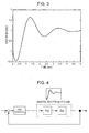
- Fig. 4 is a block diagram of PID control on an inverse response system that exhibits oscillatory behavior as illustrated in Fig. 3 . Such a control system is also disclosed in Fig. 7 or other part of PTL 2.
- Fig. 5 shows results obtained after the control system in Fig. 4 is controlled (step response).
- the effect of the inverse response yields almost no D gain (derivative gain), whereby the oscillatory behavior cannot be suppressed.
- a P gain proportional gain
- the control system is thus mainly constituted by an I gain (integral gain). Consequently, the response is very slow and even so, the response exhibits an oscillatory response wave form.
- the inverse response system has the following control problems.
- an object of the present invention is to provide a control device that can reliably control an inverse response system.
- the present invention provides the following technical means.
- a control device for an inverse response system is a control device that controls a control target having inverse response characteristics that cause initial response in a direction opposite to a change direction of an input.
- the control device includes an inverse response compensation system that compensates for the inverse response characteristics of the control target.
- the inverse response compensation system is configured to calculate a comparison value between an output of the control target and an output of the control target from which at least one or all of unstable zeros is/are removed and to feed the calculated comparison value back to an input side of the control target.
- control target is a tire running test apparatus that includes an endless belt wound around a pair of drums and a test tire disposed so as to roll over the belt, and a rocking angle of the drums or a rocking force of the drums serves as an input of the control target and a position of the belt serves as the output of the control target.
- the control device is capable of reliably controlling an inverse response system.
- a typical example of the inverse response system 2 is an apparatus for performing a running test on a tire T disclosed in PTL 1 (Japanese Unexamined Patent Application Publication No. 2010-122006 ).
- Fig. 8 illustrates an apparatus 50 for performing a running test on a tire T.
- This tire running test apparatus 50 includes a driving drum 52 coupled with a driving motor 51 and rotatable forward and backward, a driven drum 53 disposed so as to be spaced apart from the driving drum 52 and so that the axes of the driven drum 53 and the driving drum 52 are parallel to each other, and an endless belt 54 wound around the driving drum 52 and the driven drum 53.
- a test tire T is grounded on a road surface (test road surface) formed on a flat surface of the belt 54.
- the tire running test apparatus 50 can evaluate the running characteristics of the tire T by grounding the tire T on and rolling the tire T over the test road surface of the belt 54.
- the tire running test apparatus 50 also includes a belt meandering preventing device 55.
- the belt meandering preventing device 55 corrects meandering of the belt 54 or displacement of the belt 54 by rocking the driven drum 53, out of the driving drum 52 and the driven drum 53 of the tire running test apparatus 50, with respect to the driving drum 52.
- the belt meandering preventing device 55 includes drum rocking means 56 for rocking the driven drum 53 with respect to the driving drum 52 around a rocking axis extending in the vertical direction, and a controlling unit 57 that controls the drum rocking means 56.
- the drum rocking means 56 can change the position of the belt 54 in accordance with rocking parameters such as the rocking angle ⁇ , the speed of rocking ⁇ ', or the rocking force.
- the belt meandering preventing device 55 rocks the driven drum 53 after the belt position is measured with a sensor 58 or other devices to control the belt position.
- the effect of the elasticity of the belt 54 or other effects may cause the belt 54 to firstly move in the direction opposite to the commanded direction at the initial timing of response and then move in the direction of the commanded value (see Fig. 1 and Fig. 3 ).
- the system can be regarded as an inverse response system 2.
- Fig. 6 illustrates an embodiment of the present invention and is a block diagram of a control system that exhibits the characteristics of the tire running test apparatus 50, that is, an inverse response system 2, and a control device 1 that controls the inverse response system 2.
- the inverse response system 2 which is a control target, is constituted by a minimum phase system P(s) and unstable zeros Z(s) into which outputs of the minimum phase system P(s) are input.
- the minimum phase system P(s) is a system obtained by removing all the unstable zeros Z(s) from the dynamic characteristics of the tire running test apparatus 50. With there being the unstable zeros Z(s), the inverse response system 2 exhibits inverse response characteristics.
- P(s) is regarded as a minimum phase system. P(s) does not exhibit an inverse response unless P(s) includes unstable zeros whose response is slower than stable poles of P(s) although it includes unstable zeros whose response is faster. Thus, P(s) is regarded as an approximate minimum phase system that does not include unstable zeros slower than stable poles and at least one or all of the slow unstable zeros is/are integrated into Z(s). Even in this form, the following discussion and the effects hold true.
- a PID control device 3 On the input side of the inverse response system 2, a PID control device 3 is provided for controlling the inverse response system 2. A target input value is input into the inverse response system 2 through the PID control device 3, whereby the inverse response system 2 is controlled.
- the control device 1 includes an inverse response compensation system 5 (compensation loop) conforming to an idea of a Smith predictor (dead-time compensation system).
- the inventor of the present invention has found that dead time is regarded as one of the unstable zeros Z(s) and achieved the present invention on the basis of the effectiveness of the Smith compensation in dead-time compensation.
- the inverse response compensation system 5 includes two expressions P(s) in parallel and into each of which signals diverging from a value that is to be input into the inverse response system 2 (output of the PID control device 3) are input.
- An output from a first P(s) is directly output while an output from a second P(s) is input into Z(s).
- An output from Z(s) is a negative value and added to the output of the first P(s).
- the signal subjected to addition is added to the output of the inverse response system 2 (control target) and then fed back as an input into the PID control device 3 (negatively fed back).
- P(s) and Z(s) of the inverse response compensation system 5 are expressed by the same transfer functions as the minimum phase system P(s) and unstable zeros Z(s) of the inverse response system 2.
- the inverse response compensation system 5 removes a portion (P(s) + Z(s)) that reproduces a control target, which is the inverse response system 2, and Z(s) into which at least one or all of the unstable zeros is/are integrated.
- the inverse response compensation system 5 according to the embodiment implements PID control independent of the inverse response by adding the improved difference of the control target P(s) to the actual output and then feeding the resultant back to an input side.
- the inverse response compensation system 5 calculates a comparison value between an output of a control target (P(s) + Z(s)) and an output (P(s)) of the control target from which at least one or all of the unstable zeros is/are removed and negatively feeds the calculated comparison value (difference) back to an input side of the control target.
- the value fed back to the PID control device 3 is the output of the inverse response system 2 itself.
- the value is assumed to correspond to a position control loop (control loop of a rocking angle ⁇ ) in the tire running test apparatus 50 illustrated in Fig. 8 .
- Fig. 7 shows results of control performed by the control device 1 according to the embodiment.
- the control conditions are the same as those in the case of Fig. 5 .
- the PID control device 3 can reliably perform controls of D control and P control and thus can obtain immediate control response as illustrated in Fig. 7 .
- the apparatus operates in the opposite direction for an instant immediately after the activation in order to achieve immediate control response.
- the characteristics of the control target inevitably increase the inverse response in the opposite direction for achieving immediate response. Even if such inverse response occurs, it would negligibly exert the effect when applied to the actual apparatus.
- the control device according to the embodiment is very effective because it can immediately control the response following the inverse response.
- the control device 1 includes the inverse response compensation system 5.
- the control device 1 can have a high control gain and can improve the responsiveness.
- the existence of the inverse response compensation system 5 makes the control target a control system free from unstable zeros that exhibit inverse response.
- the control device 1 can perform PID control (particularly D control and P control) independently of the effect of the inverse response.
- the use of the control device 1 according to the present invention enables reliable control of the inverse response system 2.
- the embodiment disclosed herein is a mere example from every aspect and should be understood as being nonlimitative. Particularly, what is not clearly disclosed in the disclosed embodiment, such as driving conditions, operation conditions, various parameters, dimensions of structures, the weight, or the volume does not deviate from the range within which persons having ordinary skill in the art usually use.
- the embodiment uses the values easily assumable by persons having ordinary skill in the art.
- control technology of the present invention is not limited to one designed for the apparatus 50 for running test of a tire T and is also applicable to any system expressed by, for example, the inverse response system 2.
Landscapes
- Physics & Mathematics (AREA)
- General Physics & Mathematics (AREA)
- Engineering & Computer Science (AREA)
- Automation & Control Theory (AREA)
- Mechanical Engineering (AREA)
- Feedback Control In General (AREA)
Abstract
Description
- The present invention relates to a technology of controlling a control target having inverse response characteristics (inverse response system).
- In a tire running test apparatus disclosed in
PTL 1, for example, a belt wound around a pair of drums moves side to side during the tire test or deviates from the appropriate position in some cases. Thus, the tire running test apparatus controls the belt position while the angle at which the drums rock is made variable after the belt position has been measured. - In a control system such as this tire running test apparatus, the belt, which is a control target, may move in the direction of a command value after firstly moving in the inverse direction at the initial timing of the control due to effects such as the effect of the elasticity of the belt (portion indicated by A in
Fig. 1 ). Such a system that responds so that an output is firstly deflected in an inverse direction at the time of control is called an inverse response system. If the inverse response system has linear dynamic characteristics, the inverse response system is a non-minimum phase system that has a transfer function including unstable zeros. - As illustrated in
Fig. 2 , when illustrated in a block diagram, the inverse response system can be separated into a minimum phase system P(s) and unstable zeros Z(s). - Here, a polynomial is referred to as a minimum phase polynomial when the real parts of all the roots that satisfy the polynomial = 0 are negative. A system that is a linear system and in which both the denominator polynomial and the numerator polynomial of a transfer function are minimum phase polynomials is referred to as a minimum phase system. In other words, a minimum phase system is a stable system expressed by a transfer function in which all the zeros (roots of numerator polynomial = 0) and the poles (roots of denominator polynomial = 0) are stable (real parts are negative). Meanwhile, unstable zeros are zeros that are unstable and include a positive real part and a system expressed by a transfer function including unstable zeros is referred to as a non-minimum phase system. When unstable zeros, which are slower than stable poles, are included, the non-minimum phase system exhibits inverse response characteristics. For separation of the inverse response system into a minimum phase system P(s) and unstable zeros Z(s), when not all the unstable zeros are integrated into Z(s) but at least one of the unstable zeros is integrated into Z(s) and the remaining unstable zeros are left in P(s), P(s) does not become a minimum phase system but becomes a non-minimum phase system.
- Examples of a technology for controlling such an inverse response system include a device disclosed in
PTL 2. A device for suppressing pulsation of an electric motor disclosed inPTL 2 performs Fourier-transform on pulsation detection values of an electric motor driven by an inverter, detects pulsation components of an appropriate frequency in the form of two Fourier coefficients, and performs learning control using a learning controller so that the pulsation is suppressed. Thus, the device for suppressing pulsation suppresses pulsation by superimposing the learned pulsation compensation current on a d-axis current command value, a q-axis current command value, or both d-axis and q-axis current command values of a rotating system of coordinates in a vector control. In the device for suppressing pulsation, the learning control system for pulsation suppression with detection of the two Fourier coefficients is formed in a complex vector plane and the device includes means for calculating the pulsation compensation current. -
- PTL 1: Japanese Unexamined Patent Application Publication No.
2010-122006 - PTL 2: Domestic Re-publication of
PCT International Publication for Patent Application No. 2010/24194 - The inverse response system described above moves, at the initial timing of response, in the direction opposite to the direction of an input, and thus the inverse response system has low controllability. Particularly, in the case where a system, despite being an inverse response system, exhibits oscillatory behavior as illustrated in
Fig. 3 (when denominator poles of a transfer function include oscillatory poles in which "imaginary part » real parts"), the system has lower controllability: -
Fig. 4 is a block diagram of PID control on an inverse response system that exhibits oscillatory behavior as illustrated inFig. 3 . Such a control system is also disclosed inFig. 7 or other part ofPTL 2. -
Fig. 5 shows results obtained after the control system inFig. 4 is controlled (step response). In the control system ofFig. 4 , the effect of the inverse response yields almost no D gain (derivative gain), whereby the oscillatory behavior cannot be suppressed. Thus, a P gain (proportional gain) cannot be increased either and the control system is thus mainly constituted by an I gain (integral gain). Consequently, the response is very slow and even so, the response exhibits an oscillatory response wave form. - In summary, the inverse response system has the following control problems.
- (1) Since an inverse response opposite to the change direction input to a control target occurs firstly, the inverse response system has very low controllability.
- (2) Although an application of D control (derivative control) is attempted to control a non-minimum phase system including an inverse response system, a D gain that changes the control input in accordance with the change in an output wave form functions in an unstable direction in the above-described inverse response. Thus, almost no D gain can be provided. Particularly, an inverse response system that exhibits oscillatory behavior as illustrated in
Fig. 3 is unable to be subjected to oscillation control using the D control. - (3) Since it is not possible to perform oscillation control using the D control, P control (proportional control) can be only performed within a range within which oscillation is not excited, whereby the main control of the control system is left to I control (integral control). However, improvement of responsiveness using the I control is limited, whereby only a very slow control response is obtained.
- In view of the above problems, an object of the present invention is to provide a control device that can reliably control an inverse response system.
- To accomplish the above object, the present invention provides the following technical means.
- A control device for an inverse response system according to the present invention is a control device that controls a control target having inverse response characteristics that cause initial response in a direction opposite to a change direction of an input. The control device includes an inverse response compensation system that compensates for the inverse response characteristics of the control target. In the control device, the inverse response compensation system is configured to calculate a comparison value between an output of the control target and an output of the control target from which at least one or all of unstable zeros is/are removed and to feed the calculated comparison value back to an input side of the control target.
- Preferably, the control target is a tire running test apparatus that includes an endless belt wound around a pair of drums and a test tire disposed so as to roll over the belt, and a rocking angle of the drums or a rocking force of the drums serves as an input of the control target and a position of the belt serves as the output of the control target.
- The control device according to the present invention is capable of reliably controlling an inverse response system.
-
- [
Fig. 1] Fig. 1 illustrates an example of step response of an inverse response system. - [
Fig. 2] Fig. 2 is a block diagram of an inverse response system. - [
Fig. 3] Fig. 3 illustrates another example of step response of an inverse response system. - [
Fig. 4] Fig. 4 is a block diagram of PID control performed on an inverse response system. - [
Fig. 5] Fig. 5 shows the results of control performed using the control system ofFig. 4 . - [
Fig. 6] Fig. 6 is a block diagram of a control device according to an embodiment of the present invention. - [
Fig. 7] Fig. 7 shows the results of control performed using the control device illustrated inFig. 6 . - [
Fig. 8] Fig. 8 is a schematic view of a tire running test apparatus. - Referring now to the drawings, a control device for an inverse response system (non-minimum phase system including an inverse response system) according to an embodiment of the present invention is described below.
- Firstly, before a
control device 1 according to an embodiment is described, aninverse response system 2 is described. - A typical example of the
inverse response system 2 is an apparatus for performing a running test on a tire T disclosed in PTL 1 (Japanese Unexamined Patent Application Publication No.2010-122006 Fig. 8 illustrates anapparatus 50 for performing a running test on a tire T. - This tire
running test apparatus 50 includes adriving drum 52 coupled with a drivingmotor 51 and rotatable forward and backward, a drivendrum 53 disposed so as to be spaced apart from thedriving drum 52 and so that the axes of the drivendrum 53 and thedriving drum 52 are parallel to each other, and anendless belt 54 wound around thedriving drum 52 and the drivendrum 53. A test tire T is grounded on a road surface (test road surface) formed on a flat surface of thebelt 54. The tirerunning test apparatus 50 can evaluate the running characteristics of the tire T by grounding the tire T on and rolling the tire T over the test road surface of thebelt 54. - The tire
running test apparatus 50 also includes a belt meandering preventingdevice 55. The belt meandering preventingdevice 55 corrects meandering of thebelt 54 or displacement of thebelt 54 by rocking the drivendrum 53, out of the drivingdrum 52 and the drivendrum 53 of the tire runningtest apparatus 50, with respect to the drivingdrum 52. - The belt meandering preventing
device 55 includes drum rocking means 56 for rocking the drivendrum 53 with respect to the drivingdrum 52 around a rocking axis extending in the vertical direction, and a controllingunit 57 that controls the drum rocking means 56. The drum rocking means 56 can change the position of thebelt 54 in accordance with rocking parameters such as the rocking angle θ, the speed of rocking θ', or the rocking force. The belt meandering preventingdevice 55 rocks the drivendrum 53 after the belt position is measured with asensor 58 or other devices to control the belt position. - In a system typified by the tire running
test apparatus 50, the effect of the elasticity of thebelt 54 or other effects may cause thebelt 54 to firstly move in the direction opposite to the commanded direction at the initial timing of response and then move in the direction of the commanded value (seeFig. 1 andFig. 3 ). Thus, the system can be regarded as aninverse response system 2. -
Fig. 6 illustrates an embodiment of the present invention and is a block diagram of a control system that exhibits the characteristics of the tire runningtest apparatus 50, that is, aninverse response system 2, and acontrol device 1 that controls theinverse response system 2. - The
inverse response system 2, which is a control target, is constituted by a minimum phase system P(s) and unstable zeros Z(s) into which outputs of the minimum phase system P(s) are input. The minimum phase system P(s) is a system obtained by removing all the unstable zeros Z(s) from the dynamic characteristics of the tire runningtest apparatus 50. With there being the unstable zeros Z(s), theinverse response system 2 exhibits inverse response characteristics. - Here, P(s) is regarded as a minimum phase system. P(s) does not exhibit an inverse response unless P(s) includes unstable zeros whose response is slower than stable poles of P(s) although it includes unstable zeros whose response is faster. Thus, P(s) is regarded as an approximate minimum phase system that does not include unstable zeros slower than stable poles and at least one or all of the slow unstable zeros is/are integrated into Z(s). Even in this form, the following discussion and the effects hold true.
- On the input side of the
inverse response system 2, aPID control device 3 is provided for controlling theinverse response system 2. A target input value is input into theinverse response system 2 through thePID control device 3, whereby theinverse response system 2 is controlled. - Besides the
inverse response system 2, thecontrol device 1 according to the embodiment includes an inverse response compensation system 5 (compensation loop) conforming to an idea of a Smith predictor (dead-time compensation system). The inventor of the present invention has found that dead time is regarded as one of the unstable zeros Z(s) and achieved the present invention on the basis of the effectiveness of the Smith compensation in dead-time compensation. - As illustrated in
Fig. 6 , the inverseresponse compensation system 5 includes two expressions P(s) in parallel and into each of which signals diverging from a value that is to be input into the inverse response system 2 (output of the PID control device 3) are input. An output from a first P(s) is directly output while an output from a second P(s) is input into Z(s). An output from Z(s) is a negative value and added to the output of the first P(s). The signal subjected to addition is added to the output of the inverse response system 2 (control target) and then fed back as an input into the PID control device 3 (negatively fed back). Here, P(s) and Z(s) of the inverseresponse compensation system 5 are expressed by the same transfer functions as the minimum phase system P(s) and unstable zeros Z(s) of theinverse response system 2. - In short, the inverse
response compensation system 5 according to the embodiment removes a portion (P(s) + Z(s)) that reproduces a control target, which is theinverse response system 2, and Z(s) into which at least one or all of the unstable zeros is/are integrated. Thus, the inverseresponse compensation system 5 according to the embodiment implements PID control independent of the inverse response by adding the improved difference of the control target P(s) to the actual output and then feeding the resultant back to an input side. In other words, the inverseresponse compensation system 5 calculates a comparison value between an output of a control target (P(s) + Z(s)) and an output (P(s)) of the control target from which at least one or all of the unstable zeros is/are removed and negatively feeds the calculated comparison value (difference) back to an input side of the control target. - The value fed back to the
PID control device 3 is the output of theinverse response system 2 itself. Thus, the value is assumed to correspond to a position control loop (control loop of a rocking angle θ) in the tire runningtest apparatus 50 illustrated inFig. 8 . -
Fig. 7 shows results of control performed by thecontrol device 1 according to the embodiment. The control conditions are the same as those in the case ofFig. 5 . - Since the embodiment (example) includes the inverse
response compensation system 5, thePID control device 3 can reliably perform controls of D control and P control and thus can obtain immediate control response as illustrated inFig. 7 . As illustrated with the response curve illustrated inFig. 7 , the apparatus operates in the opposite direction for an instant immediately after the activation in order to achieve immediate control response. The characteristics of the control target inevitably increase the inverse response in the opposite direction for achieving immediate response. Even if such inverse response occurs, it would negligibly exert the effect when applied to the actual apparatus. On the contrary, the control device according to the embodiment is very effective because it can immediately control the response following the inverse response. - As described above, the
control device 1 according to the present invention includes the inverseresponse compensation system 5. Thus, thecontrol device 1 can have a high control gain and can improve the responsiveness. In addition, the existence of the inverseresponse compensation system 5 makes the control target a control system free from unstable zeros that exhibit inverse response. Thus, thecontrol device 1 can perform PID control (particularly D control and P control) independently of the effect of the inverse response. Specifically, the use of thecontrol device 1 according to the present invention enables reliable control of theinverse response system 2. - The embodiment disclosed herein is a mere example from every aspect and should be understood as being nonlimitative. Particularly, what is not clearly disclosed in the disclosed embodiment, such as driving conditions, operation conditions, various parameters, dimensions of structures, the weight, or the volume does not deviate from the range within which persons having ordinary skill in the art usually use. The embodiment uses the values easily assumable by persons having ordinary skill in the art.
- The control technology of the present invention is not limited to one designed for the
apparatus 50 for running test of a tire T and is also applicable to any system expressed by, for example, theinverse response system 2. - The application is related to Japanese Patent Application (Japanese Patent Application No.
2012-229926) filed October 17, 2012 -
- 1
- control device
- 2
- inverse response system
- 3
- PID control device
- 5
- inverse response compensation system
- 50
- tire running test apparatus
- 51
- driving motor
- 52
- driving drum
- 53
- driven drum
- 54
- belt
- 55
- belt meandering preventing device
- 56
- drum rocking means
- 57
- controlling unit
- 58
- sensor
- T
- tire
Claims (2)
- A control device for an inverse response system that controls a control target having inverse response characteristics that cause initial response in a direction opposite to a change direction of an input, comprising:an inverse response compensation system that compensates for the inverse response characteristics of the control target,wherein the inverse response compensation system is configured to calculate a comparison value between an output of the control target and an output of the control target from which at least one or all of unstable zeros is/are removed and to feed the calculated comparison value back to an input side of the control target.
- The control device for an inverse response system according to Claim 1,
wherein the control target is a tire running test apparatus that includes an endless belt wound around a pair of drums and a test tire disposed so as to roll over the belt, and
wherein a rocking angle of the drums or a rocking force of the drums serves as an input of the control target and a position of the belt serves as the output of the control target.
Applications Claiming Priority (2)
| Application Number | Priority Date | Filing Date | Title |
|---|---|---|---|
| JP2012229926A JP5541751B2 (en) | 2012-10-17 | 2012-10-17 | Inverse response system controller |
| PCT/JP2013/078018 WO2014061683A1 (en) | 2012-10-17 | 2013-10-15 | Control device for inverse response system |
Publications (3)
| Publication Number | Publication Date |
|---|---|
| EP2911017A1 true EP2911017A1 (en) | 2015-08-26 |
| EP2911017A4 EP2911017A4 (en) | 2016-08-31 |
| EP2911017B1 EP2911017B1 (en) | 2019-07-03 |
Family
ID=50488244
Family Applications (1)
| Application Number | Title | Priority Date | Filing Date |
|---|---|---|---|
| EP13847899.5A Not-in-force EP2911017B1 (en) | 2012-10-17 | 2013-10-15 | Control device for inverse response system |
Country Status (4)
| Country | Link |
|---|---|
| US (1) | US10007237B2 (en) |
| EP (1) | EP2911017B1 (en) |
| JP (1) | JP5541751B2 (en) |
| WO (1) | WO2014061683A1 (en) |
Families Citing this family (2)
| Publication number | Priority date | Publication date | Assignee | Title |
|---|---|---|---|---|
| JP6361874B2 (en) * | 2014-08-07 | 2018-07-25 | 日本放送協会 | Transfer function approximating device, program thereof and method thereof |
| JP6525076B1 (en) | 2018-02-13 | 2019-06-05 | 株式会社明電舎 | Controller of dynamometer system |
Family Cites Families (7)
| Publication number | Priority date | Publication date | Assignee | Title |
|---|---|---|---|---|
| US8180464B2 (en) * | 2002-04-18 | 2012-05-15 | Cleveland State University | Extended active disturbance rejection controller |
| KR100618885B1 (en) * | 2005-02-04 | 2006-09-01 | 삼성전자주식회사 | Low frequency disturbance compensation control device and disk drive using the same |
| JP2006215993A (en) * | 2005-02-07 | 2006-08-17 | Nissan Motor Co Ltd | Active vibration control apparatus and active vibration control method |
| JP4747798B2 (en) * | 2005-11-22 | 2011-08-17 | 東洋ゴム工業株式会社 | Tire wear test method |
| JP5058950B2 (en) * | 2008-11-18 | 2012-10-24 | 株式会社神戸製鋼所 | Belt meandering prevention device and belt meandering prevention method for running test device |
| KR20110003551A (en) | 2008-05-28 | 2011-01-12 | 가부시키가이샤 고베 세이코쇼 | Belt meandering device and belt meandering method of driving test device |
| JP5088413B2 (en) * | 2008-08-26 | 2012-12-05 | 株式会社明電舎 | Electric motor pulsation suppression device |
-
2012
- 2012-10-17 JP JP2012229926A patent/JP5541751B2/en active Active
-
2013
- 2013-10-15 WO PCT/JP2013/078018 patent/WO2014061683A1/en not_active Ceased
- 2013-10-15 EP EP13847899.5A patent/EP2911017B1/en not_active Not-in-force
- 2013-10-15 US US14/433,531 patent/US10007237B2/en not_active Expired - Fee Related
Also Published As
| Publication number | Publication date |
|---|---|
| EP2911017B1 (en) | 2019-07-03 |
| WO2014061683A1 (en) | 2014-04-24 |
| JP2014081822A (en) | 2014-05-08 |
| EP2911017A4 (en) | 2016-08-31 |
| US10007237B2 (en) | 2018-06-26 |
| US20150227119A1 (en) | 2015-08-13 |
| JP5541751B2 (en) | 2014-07-09 |
Similar Documents
| Publication | Publication Date | Title |
|---|---|---|
| US7849957B2 (en) | Control apparatus for electric power steering | |
| KR101521487B1 (en) | Dynamometer system | |
| EP2715931B1 (en) | Motor control with voltage harmonic shaping | |
| US9647583B2 (en) | Variable magnetization machine controller | |
| US20150251692A1 (en) | Motor control device and electric power steering device | |
| JP5345244B2 (en) | Web center position control device, method and program, and web trimming device | |
| KR101774073B1 (en) | Electromagnetic vibration suppression device and computer-readable storage medium having electromagnetic vibration suppression control program | |
| JP6703338B2 (en) | Electric power steering device | |
| WO2017203595A1 (en) | Electric power steering device | |
| US10007237B2 (en) | Control device for inverse response system | |
| JP2015173548A (en) | Vibration suppression control device for vehicle | |
| US20200180684A1 (en) | Electric power steering device | |
| KR20130011840A (en) | Steering control device of motor driven powersteering system | |
| KR20160139457A (en) | Vehicle type Trailer Stability Control method ans system | |
| JP5553876B2 (en) | Non-localized control device with dead time | |
| KR101613561B1 (en) | Method and apparatus for managing right and left torque balance of a wheelchair | |
| JP5863620B2 (en) | Non-localized control device with dead time | |
| JP6614031B2 (en) | Inspection device for electric power steering control device and electric power steering device equipped with the same | |
| EP3078572A1 (en) | Electric power steering control device | |
| WO2016056143A1 (en) | Electric-motor control device | |
| EP3203332A1 (en) | Automatic control device | |
| JP6123182B2 (en) | Motor control device | |
| JP2012001009A (en) | Control device | |
| KR20130054638A (en) | Lane keeping steering method and apparatus using variable ttlc | |
| JP2007004808A (en) | Vibration control method |
Legal Events
| Date | Code | Title | Description |
|---|---|---|---|
| PUAI | Public reference made under article 153(3) epc to a published international application that has entered the european phase |
Free format text: ORIGINAL CODE: 0009012 |
|
| 17P | Request for examination filed |
Effective date: 20150430 |
|
| AK | Designated contracting states |
Kind code of ref document: A1 Designated state(s): AL AT BE BG CH CY CZ DE DK EE ES FI FR GB GR HR HU IE IS IT LI LT LU LV MC MK MT NL NO PL PT RO RS SE SI SK SM TR |
|
| AX | Request for extension of the european patent |
Extension state: BA ME |
|
| DAX | Request for extension of the european patent (deleted) | ||
| RIC1 | Information provided on ipc code assigned before grant |
Ipc: G05B 11/36 20060101AFI20160721BHEP Ipc: G01M 17/02 20060101ALI20160721BHEP |
|
| RA4 | Supplementary search report drawn up and despatched (corrected) |
Effective date: 20160801 |
|
| GRAP | Despatch of communication of intention to grant a patent |
Free format text: ORIGINAL CODE: EPIDOSNIGR1 |
|
| STAA | Information on the status of an ep patent application or granted ep patent |
Free format text: STATUS: GRANT OF PATENT IS INTENDED |
|
| INTG | Intention to grant announced |
Effective date: 20190215 |
|
| RIN1 | Information on inventor provided before grant (corrected) |
Inventor name: NISHIDA, YOSHIHARU |
|
| GRAS | Grant fee paid |
Free format text: ORIGINAL CODE: EPIDOSNIGR3 |
|
| GRAA | (expected) grant |
Free format text: ORIGINAL CODE: 0009210 |
|
| STAA | Information on the status of an ep patent application or granted ep patent |
Free format text: STATUS: THE PATENT HAS BEEN GRANTED |
|
| AK | Designated contracting states |
Kind code of ref document: B1 Designated state(s): AL AT BE BG CH CY CZ DE DK EE ES FI FR GB GR HR HU IE IS IT LI LT LU LV MC MK MT NL NO PL PT RO RS SE SI SK SM TR |
|
| REG | Reference to a national code |
Ref country code: GB Ref legal event code: FG4D |
|
| REG | Reference to a national code |
Ref country code: CH Ref legal event code: EP Ref country code: AT Ref legal event code: REF Ref document number: 1151727 Country of ref document: AT Kind code of ref document: T Effective date: 20190715 |
|
| REG | Reference to a national code |
Ref country code: IE Ref legal event code: FG4D |
|
| REG | Reference to a national code |
Ref country code: DE Ref legal event code: R096 Ref document number: 602013057498 Country of ref document: DE |
|
| REG | Reference to a national code |
Ref country code: NL Ref legal event code: MP Effective date: 20190703 |
|
| REG | Reference to a national code |
Ref country code: LT Ref legal event code: MG4D |
|
| REG | Reference to a national code |
Ref country code: AT Ref legal event code: MK05 Ref document number: 1151727 Country of ref document: AT Kind code of ref document: T Effective date: 20190703 |
|
| PG25 | Lapsed in a contracting state [announced via postgrant information from national office to epo] |
Ref country code: PT Free format text: LAPSE BECAUSE OF FAILURE TO SUBMIT A TRANSLATION OF THE DESCRIPTION OR TO PAY THE FEE WITHIN THE PRESCRIBED TIME-LIMIT Effective date: 20191104 Ref country code: NL Free format text: LAPSE BECAUSE OF FAILURE TO SUBMIT A TRANSLATION OF THE DESCRIPTION OR TO PAY THE FEE WITHIN THE PRESCRIBED TIME-LIMIT Effective date: 20190703 Ref country code: AT Free format text: LAPSE BECAUSE OF FAILURE TO SUBMIT A TRANSLATION OF THE DESCRIPTION OR TO PAY THE FEE WITHIN THE PRESCRIBED TIME-LIMIT Effective date: 20190703 Ref country code: HR Free format text: LAPSE BECAUSE OF FAILURE TO SUBMIT A TRANSLATION OF THE DESCRIPTION OR TO PAY THE FEE WITHIN THE PRESCRIBED TIME-LIMIT Effective date: 20190703 Ref country code: BG Free format text: LAPSE BECAUSE OF FAILURE TO SUBMIT A TRANSLATION OF THE DESCRIPTION OR TO PAY THE FEE WITHIN THE PRESCRIBED TIME-LIMIT Effective date: 20191003 Ref country code: SE Free format text: LAPSE BECAUSE OF FAILURE TO SUBMIT A TRANSLATION OF THE DESCRIPTION OR TO PAY THE FEE WITHIN THE PRESCRIBED TIME-LIMIT Effective date: 20190703 Ref country code: FI Free format text: LAPSE BECAUSE OF FAILURE TO SUBMIT A TRANSLATION OF THE DESCRIPTION OR TO PAY THE FEE WITHIN THE PRESCRIBED TIME-LIMIT Effective date: 20190703 Ref country code: NO Free format text: LAPSE BECAUSE OF FAILURE TO SUBMIT A TRANSLATION OF THE DESCRIPTION OR TO PAY THE FEE WITHIN THE PRESCRIBED TIME-LIMIT Effective date: 20191003 Ref country code: CZ Free format text: LAPSE BECAUSE OF FAILURE TO SUBMIT A TRANSLATION OF THE DESCRIPTION OR TO PAY THE FEE WITHIN THE PRESCRIBED TIME-LIMIT Effective date: 20190703 Ref country code: LT Free format text: LAPSE BECAUSE OF FAILURE TO SUBMIT A TRANSLATION OF THE DESCRIPTION OR TO PAY THE FEE WITHIN THE PRESCRIBED TIME-LIMIT Effective date: 20190703 |
|
| PG25 | Lapsed in a contracting state [announced via postgrant information from national office to epo] |
Ref country code: LV Free format text: LAPSE BECAUSE OF FAILURE TO SUBMIT A TRANSLATION OF THE DESCRIPTION OR TO PAY THE FEE WITHIN THE PRESCRIBED TIME-LIMIT Effective date: 20190703 Ref country code: RS Free format text: LAPSE BECAUSE OF FAILURE TO SUBMIT A TRANSLATION OF THE DESCRIPTION OR TO PAY THE FEE WITHIN THE PRESCRIBED TIME-LIMIT Effective date: 20190703 Ref country code: GR Free format text: LAPSE BECAUSE OF FAILURE TO SUBMIT A TRANSLATION OF THE DESCRIPTION OR TO PAY THE FEE WITHIN THE PRESCRIBED TIME-LIMIT Effective date: 20191004 Ref country code: IS Free format text: LAPSE BECAUSE OF FAILURE TO SUBMIT A TRANSLATION OF THE DESCRIPTION OR TO PAY THE FEE WITHIN THE PRESCRIBED TIME-LIMIT Effective date: 20191103 Ref country code: AL Free format text: LAPSE BECAUSE OF FAILURE TO SUBMIT A TRANSLATION OF THE DESCRIPTION OR TO PAY THE FEE WITHIN THE PRESCRIBED TIME-LIMIT Effective date: 20190703 Ref country code: ES Free format text: LAPSE BECAUSE OF FAILURE TO SUBMIT A TRANSLATION OF THE DESCRIPTION OR TO PAY THE FEE WITHIN THE PRESCRIBED TIME-LIMIT Effective date: 20190703 |
|
| PG25 | Lapsed in a contracting state [announced via postgrant information from national office to epo] |
Ref country code: TR Free format text: LAPSE BECAUSE OF FAILURE TO SUBMIT A TRANSLATION OF THE DESCRIPTION OR TO PAY THE FEE WITHIN THE PRESCRIBED TIME-LIMIT Effective date: 20190703 |
|
| PG25 | Lapsed in a contracting state [announced via postgrant information from national office to epo] |
Ref country code: DK Free format text: LAPSE BECAUSE OF FAILURE TO SUBMIT A TRANSLATION OF THE DESCRIPTION OR TO PAY THE FEE WITHIN THE PRESCRIBED TIME-LIMIT Effective date: 20190703 Ref country code: PL Free format text: LAPSE BECAUSE OF FAILURE TO SUBMIT A TRANSLATION OF THE DESCRIPTION OR TO PAY THE FEE WITHIN THE PRESCRIBED TIME-LIMIT Effective date: 20190703 Ref country code: IT Free format text: LAPSE BECAUSE OF FAILURE TO SUBMIT A TRANSLATION OF THE DESCRIPTION OR TO PAY THE FEE WITHIN THE PRESCRIBED TIME-LIMIT Effective date: 20190703 Ref country code: RO Free format text: LAPSE BECAUSE OF FAILURE TO SUBMIT A TRANSLATION OF THE DESCRIPTION OR TO PAY THE FEE WITHIN THE PRESCRIBED TIME-LIMIT Effective date: 20190703 Ref country code: EE Free format text: LAPSE BECAUSE OF FAILURE TO SUBMIT A TRANSLATION OF THE DESCRIPTION OR TO PAY THE FEE WITHIN THE PRESCRIBED TIME-LIMIT Effective date: 20190703 |
|
| PG25 | Lapsed in a contracting state [announced via postgrant information from national office to epo] |
Ref country code: SM Free format text: LAPSE BECAUSE OF FAILURE TO SUBMIT A TRANSLATION OF THE DESCRIPTION OR TO PAY THE FEE WITHIN THE PRESCRIBED TIME-LIMIT Effective date: 20190703 Ref country code: IS Free format text: LAPSE BECAUSE OF FAILURE TO SUBMIT A TRANSLATION OF THE DESCRIPTION OR TO PAY THE FEE WITHIN THE PRESCRIBED TIME-LIMIT Effective date: 20200224 Ref country code: MC Free format text: LAPSE BECAUSE OF FAILURE TO SUBMIT A TRANSLATION OF THE DESCRIPTION OR TO PAY THE FEE WITHIN THE PRESCRIBED TIME-LIMIT Effective date: 20190703 Ref country code: SK Free format text: LAPSE BECAUSE OF FAILURE TO SUBMIT A TRANSLATION OF THE DESCRIPTION OR TO PAY THE FEE WITHIN THE PRESCRIBED TIME-LIMIT Effective date: 20190703 |
|
| REG | Reference to a national code |
Ref country code: CH Ref legal event code: PL |
|
| REG | Reference to a national code |
Ref country code: DE Ref legal event code: R097 Ref document number: 602013057498 Country of ref document: DE |
|
| PLBE | No opposition filed within time limit |
Free format text: ORIGINAL CODE: 0009261 |
|
| STAA | Information on the status of an ep patent application or granted ep patent |
Free format text: STATUS: NO OPPOSITION FILED WITHIN TIME LIMIT |
|
| PG2D | Information on lapse in contracting state deleted |
Ref country code: IS |
|
| PG25 | Lapsed in a contracting state [announced via postgrant information from national office to epo] |
Ref country code: LU Free format text: LAPSE BECAUSE OF NON-PAYMENT OF DUE FEES Effective date: 20191015 Ref country code: CH Free format text: LAPSE BECAUSE OF NON-PAYMENT OF DUE FEES Effective date: 20191031 Ref country code: LI Free format text: LAPSE BECAUSE OF NON-PAYMENT OF DUE FEES Effective date: 20191031 |
|
| 26N | No opposition filed |
Effective date: 20200603 |
|
| REG | Reference to a national code |
Ref country code: BE Ref legal event code: MM Effective date: 20191031 |
|
| PG25 | Lapsed in a contracting state [announced via postgrant information from national office to epo] |
Ref country code: SI Free format text: LAPSE BECAUSE OF FAILURE TO SUBMIT A TRANSLATION OF THE DESCRIPTION OR TO PAY THE FEE WITHIN THE PRESCRIBED TIME-LIMIT Effective date: 20190703 Ref country code: BE Free format text: LAPSE BECAUSE OF NON-PAYMENT OF DUE FEES Effective date: 20191031 |
|
| GBPC | Gb: european patent ceased through non-payment of renewal fee |
Effective date: 20191015 |
|
| PG25 | Lapsed in a contracting state [announced via postgrant information from national office to epo] |
Ref country code: GB Free format text: LAPSE BECAUSE OF NON-PAYMENT OF DUE FEES Effective date: 20191015 Ref country code: IE Free format text: LAPSE BECAUSE OF NON-PAYMENT OF DUE FEES Effective date: 20191015 Ref country code: FR Free format text: LAPSE BECAUSE OF NON-PAYMENT OF DUE FEES Effective date: 20191031 |
|
| PGFP | Annual fee paid to national office [announced via postgrant information from national office to epo] |
Ref country code: DE Payment date: 20200929 Year of fee payment: 8 |
|
| PG25 | Lapsed in a contracting state [announced via postgrant information from national office to epo] |
Ref country code: CY Free format text: LAPSE BECAUSE OF FAILURE TO SUBMIT A TRANSLATION OF THE DESCRIPTION OR TO PAY THE FEE WITHIN THE PRESCRIBED TIME-LIMIT Effective date: 20190703 |
|
| PG25 | Lapsed in a contracting state [announced via postgrant information from national office to epo] |
Ref country code: MT Free format text: LAPSE BECAUSE OF FAILURE TO SUBMIT A TRANSLATION OF THE DESCRIPTION OR TO PAY THE FEE WITHIN THE PRESCRIBED TIME-LIMIT Effective date: 20190703 Ref country code: HU Free format text: LAPSE BECAUSE OF FAILURE TO SUBMIT A TRANSLATION OF THE DESCRIPTION OR TO PAY THE FEE WITHIN THE PRESCRIBED TIME-LIMIT; INVALID AB INITIO Effective date: 20131015 |
|
| REG | Reference to a national code |
Ref country code: DE Ref legal event code: R119 Ref document number: 602013057498 Country of ref document: DE |
|
| PG25 | Lapsed in a contracting state [announced via postgrant information from national office to epo] |
Ref country code: MK Free format text: LAPSE BECAUSE OF FAILURE TO SUBMIT A TRANSLATION OF THE DESCRIPTION OR TO PAY THE FEE WITHIN THE PRESCRIBED TIME-LIMIT Effective date: 20190703 |
|
| PG25 | Lapsed in a contracting state [announced via postgrant information from national office to epo] |
Ref country code: DE Free format text: LAPSE BECAUSE OF NON-PAYMENT OF DUE FEES Effective date: 20220503 |