EP2910942A1 - Testing arrangement for ultrasonic testing of a mechanical component - Google Patents
Testing arrangement for ultrasonic testing of a mechanical component Download PDFInfo
- Publication number
- EP2910942A1 EP2910942A1 EP14400010.6A EP14400010A EP2910942A1 EP 2910942 A1 EP2910942 A1 EP 2910942A1 EP 14400010 A EP14400010 A EP 14400010A EP 2910942 A1 EP2910942 A1 EP 2910942A1
- Authority
- EP
- European Patent Office
- Prior art keywords
- probe element
- leaf spring
- testing arrangement
- testing
- element support
- Prior art date
- Legal status (The legal status is an assumption and is not a legal conclusion. Google has not performed a legal analysis and makes no representation as to the accuracy of the status listed.)
- Withdrawn
Links
- 238000012360 testing method Methods 0.000 title claims abstract description 99
- 239000000523 sample Substances 0.000 claims abstract description 156
- 239000003365 glass fiber Substances 0.000 claims description 14
- 229920000049 Carbon (fiber) Polymers 0.000 claims description 10
- 239000004917 carbon fiber Substances 0.000 claims description 10
- VNWKTOKETHGBQD-UHFFFAOYSA-N methane Chemical compound C VNWKTOKETHGBQD-UHFFFAOYSA-N 0.000 claims description 10
- 238000004026 adhesive bonding Methods 0.000 claims description 7
- XLYOFNOQVPJJNP-UHFFFAOYSA-N water Substances O XLYOFNOQVPJJNP-UHFFFAOYSA-N 0.000 claims description 7
- 238000005452 bending Methods 0.000 claims description 5
- 239000004809 Teflon Substances 0.000 claims description 4
- 229920006362 Teflon® Polymers 0.000 claims description 4
- 238000005259 measurement Methods 0.000 description 7
- 238000004519 manufacturing process Methods 0.000 description 5
- 238000012423 maintenance Methods 0.000 description 4
- 238000000034 method Methods 0.000 description 4
- 238000012956 testing procedure Methods 0.000 description 4
- 239000002184 metal Substances 0.000 description 3
- 230000004913 activation Effects 0.000 description 2
- 239000000853 adhesive Substances 0.000 description 2
- 230000001070 adhesive effect Effects 0.000 description 2
- 238000007689 inspection Methods 0.000 description 2
- 239000000463 material Substances 0.000 description 2
- 239000004033 plastic Substances 0.000 description 2
- 230000008569 process Effects 0.000 description 2
- 229910000831 Steel Inorganic materials 0.000 description 1
- 230000004888 barrier function Effects 0.000 description 1
- 230000008859 change Effects 0.000 description 1
- 230000001419 dependent effect Effects 0.000 description 1
- 238000013461 design Methods 0.000 description 1
- 238000001514 detection method Methods 0.000 description 1
- 238000011161 development Methods 0.000 description 1
- 230000018109 developmental process Effects 0.000 description 1
- 238000009434 installation Methods 0.000 description 1
- 238000012986 modification Methods 0.000 description 1
- 230000004048 modification Effects 0.000 description 1
- 238000012544 monitoring process Methods 0.000 description 1
- 238000003825 pressing Methods 0.000 description 1
- 238000000275 quality assurance Methods 0.000 description 1
- 239000010959 steel Substances 0.000 description 1
- 238000011179 visual inspection Methods 0.000 description 1
- 239000002023 wood Substances 0.000 description 1
Images


Classifications
-
- G—PHYSICS
- G01—MEASURING; TESTING
- G01N—INVESTIGATING OR ANALYSING MATERIALS BY DETERMINING THEIR CHEMICAL OR PHYSICAL PROPERTIES
- G01N29/00—Investigating or analysing materials by the use of ultrasonic, sonic or infrasonic waves; Visualisation of the interior of objects by transmitting ultrasonic or sonic waves through the object
- G01N29/22—Details, e.g. general constructional or apparatus details
- G01N29/225—Supports, positioning or alignment in moving situation
-
- G—PHYSICS
- G01—MEASURING; TESTING
- G01N—INVESTIGATING OR ANALYSING MATERIALS BY DETERMINING THEIR CHEMICAL OR PHYSICAL PROPERTIES
- G01N29/00—Investigating or analysing materials by the use of ultrasonic, sonic or infrasonic waves; Visualisation of the interior of objects by transmitting ultrasonic or sonic waves through the object
- G01N29/22—Details, e.g. general constructional or apparatus details
- G01N29/225—Supports, positioning or alignment in moving situation
- G01N29/226—Handheld or portable devices
-
- G—PHYSICS
- G01—MEASURING; TESTING
- G01N—INVESTIGATING OR ANALYSING MATERIALS BY DETERMINING THEIR CHEMICAL OR PHYSICAL PROPERTIES
- G01N29/00—Investigating or analysing materials by the use of ultrasonic, sonic or infrasonic waves; Visualisation of the interior of objects by transmitting ultrasonic or sonic waves through the object
- G01N29/22—Details, e.g. general constructional or apparatus details
- G01N29/26—Arrangements for orientation or scanning by relative movement of the head and the sensor
- G01N29/265—Arrangements for orientation or scanning by relative movement of the head and the sensor by moving the sensor relative to a stationary material
Definitions
- the invention is related to a testing arrangement for ultrasonic testing of a mechanical component with the features of claim 1.
- Ultrasonic testing is particularly suitable for quality assurance of mechanical components, as it allows a reliable in-depth inspection of such mechanical components that goes beyond a mere visual inspection thereof.
- currently available ultrasonic testing arrangements that are adapted to perform such an ultrasonic testing are comparatively expensive and generally only applicable in concrete predefined testing environments. More specifically, currently available ultrasonic testing arrangements are only adapted to satisfy predetermined testing requirements with a limited number of degrees of freedom of an associated probe element. In particular, such a limited number of degrees of freedom can only be guaranteed by comparatively complex testing arrangements.
- a single ultrasonic testing arrangement may be adapted for use with exchangeable probe element supports, so that probe element supports for probe elements with differing diameters can be applied.
- exchanging the probe element supports during testing of a given mechanical component extends the time required for the testing, thereby increasing the costs thereof.
- Another problem with currently available ultrasonic testing arrangements may occur if a time critical ultrasonic testing needs to be performed with a particular probe element that is not ready for use with an existing testing arrangement.
- a suitable probe element support needs to be fabricated in order to adapt the existing testing arrangement for use with this particular probe element.
- fabrication of the suitable probe element support can be cost-intensive and time-consuming.
- an associated probe element generally needs to abut uniformly against a given mechanical component during an entire underlying testing procedure. This is achieved by pressing the associated probe element with a corresponding contact pressure against the mechanical component, e.g. by means of an associated helical spring.
- the document CN 2014 64432 U describes such a testing arrangement that presses an associated probe element with a helical spring against a mechanical component that is to be tested.
- This testing arrangement is formed of a probe tracking device used for ultrasonic flaw detection and comprises an upper layer connecting frame, a lower layer connecting frame, an upper layer helical spring, a lower layer helical spring, a connecting rod, a supporting rod and rollers.
- a pin is fixed at the upper part of the upper layer connecting frame.
- the connecting rod is fixed on the edge of the lower part of the upper layer connecting frame and a through-hole corresponding to the connecting rod is formed on the edge of the lower layer connecting frame.
- the connecting rod penetrates through the upper layer helical spring, the through-hole of the lower layer connecting frame, and the lower layer helical spring in sequence, so that the upper and the lower layer connecting frames are connected and mounted together.
- the lower end part of the connecting rod is compressed and fixed with the lower end of the lower layer helical spring, thereby mounting a barrier element.
- a supporting rod is mounted at the lower part of the lower layer connecting frame.
- the rollers are arranged at the lower part of the supporting rod and a probe element is fixedly mounted at the middle part at the lower part of the lower layer connecting frame.
- this testing arrangement requires a free an unimpeded access to a given mechanical component from its upper, i.e. top side, while e.g. an ultrasonic testing from a lateral position thereof is not possible. Furthermore, this testing arrangement is not suitable for ultrasonic testing of complex mechanical components having angled and crooked sections due to its limited number of degrees of freedom. Moreover, the contact pressure exerted by the helical spring via an associated probe element on the given mechanical component is comparatively high and may, thus, lead to breakage of the mechanical component.
- currently available ultrasonic testing arrangements may comprise some overload protection means for protecting the mechanical component against an overload caused by the contact pressure of the associated probe element.
- overload protection means for protecting the mechanical component against an overload caused by the contact pressure of the associated probe element.
- breakage may occur prior to activation of such overload protection means, e.g. prior to activation of an associated overload switch. Accordingly, it is not possible to use currently available ultrasonic testing arrangements to perform ultrasonic testing on mechanical components having a thickness of less than 2 mm.
- Another problem related to the comparatively high contact pressure exerted by the helical spring via the associated probe element on the given mechanical component consists in a possible disrupting or squeezing of a water film that needs to be maintained between the associated probe element and the given mechanical component during an underlying testing procedure in order to obtain meaningful and reliable measurements. If such a water film is disrupted or squeezed due to the comparatively high contact pressure, the measurements obtained during the underlying testing procedure can be unusable. Thus, continuous monitoring of the ultrasonic testing arrangement by respective control staff is required to guarantee that usable measurements are obtained, so that an automated ultrasonic testing is not possible.
- an object of the present invention to provide a testing arrangement for an automated ultrasonic testing of a mechanical component by means of an associated probe element that is applicable with a freely selectable orientation relative to the mechanical component and that can also be used for ultrasonic testing of comparatively thin mechanical components.
- a testing arrangement for ultrasonic testing of a mechanical component by means of an associated probe element.
- the testing arrangement comprises a probe carrier with a carrying device and a probe element support.
- the probe element support is adapted to receive the associated probe element.
- the probe element support and the carrying device are interconnected by a leaf spring.
- leaf spring refers in the context of the present invention to any flat, plate-like and/or ribbon-like spring.
- a leaf spring can be single-layered or laminated and made of plastic, metal, in particular steel, or any other suitable material, such as wood. Furthermore, combinations of these materials are also contemplated.
- the inventive testing arrangement is particularly suitable for an automated ultrasonic testing of mechanical components, as the applied leaf spring can be provided with an associated bending and torsional stiffness that allows for a continuously uniform abutment of the associated probe element against a given mechanical component that is to be tested, with a limited contact pressure. Thus, maintenance of a corresponding water film between the associated probe element and the given mechanical component can be guaranteed, even if the given mechanical component exhibits a cambered outer surface.
- the applied leaf spring is designed to be weaker than the given mechanical component by selecting an appropriate bending and torsional stiffness, so that a breakage of the mechanical component due to overload conditions can reliably be avoided. More specifically, if an overload condition occurs, the leaf spring is bended more than the given mechanical component due to its greater weakness, so that the mechanical component is protected against breakage. Furthermore, such a comparatively weak design of the leaf spring reduces a resulting contact pressure of the associated probe element against the given mechanical component, so that comparatively thin mechanical components having e.g. a thickness of less than 2 mm can also be tested securely and reliably.
- the inventive testing arrangement is realized without any articulations or lever arms due to the application of the leaf spring and, therefore, comprises reduced overall dimensions.
- the inventive testing arrangement is embodied for use with an associated standard 5 MHz probe element having a diameter of 6,35 mm, an associated installation or structural height can be reduced to approximately 5 cm.
- testing environments with limited access to the given mechanical component can be envisaged, especially independent of a respective orientation of the associated probe element relative to the given mechanical component, so that also complex mechanical components having angled and crooked sections and/or cambered outer surfaces may easily be inspected.
- the leaf spring is provided with the probe element support and mounted to the carrying device
- use of different probe elements with a given carrying device merely requires provision of a plurality of appropriate leaf springs provided with corresponding probe element supports that are suitable to receive the different probe elements.
- a quick and simple exchange of the probe elements can be enabled such that the testing arrangement can be adapted easily to changing testing requirements without requiring a change of the carrying device.
- the carrying device can in such a configuration be configured for manual use or be attached to an associated testing roboter.
- such a combination of the leaf spring and the probe element support can be fabricated in a cost-saving manner and reduces fabrication costs for the testing arrangement in general. For instance, dependent on the used leaf spring and probe element support, these fabrication costs could be reduced to approximately 10% of the fabrication costs required for fabrication of a conventional probe fixture.
- leaf springs with associated probe element supports for additional, e.g. newly developed probe elements can easily be fabricated in a cost-efficient manner so that existing testing arrangements can rapidly and simply be adapted to such additional probe elements.
- These testing arrangements further comprise a reduced number of simple and cost-efficient constituting elements that require only a reduced maintenance effort.
- the testing arrangement according to the present invention is flexible, can easily be adapted to varying testing environments independent of a required positional orientation and conforms to all relevant security standards. It is suitable for use in automated testing procedures and comparatively low-maintenance, thus reducing operation and maintenance costs. Furthermore, it has reduced overall dimensions and can, thus, advantageously be applied for testing complex mechanical components having angled and crooked sections and/or cambered outer surfaces. Moreover, it can be produced in a cost-efficient manner as it comprises a reduced number of constituting elements and can easily and rapidly be retooled. Additionally, it is adaptable to future developments and modifications of probe elements or at least their corresponding geometrical embodiments and dimensions. Finally, it is adapted to perform safe and reliable high quality measurements, as it is configured to uniformly abut against a given mechanical component without a risk for overload or disrupting or squeezing of a respective water film required for measuring.
- the leaf spring comprises a probe element support attachment part that is rigidly attached to the probe element support, and a carrying device attachment part that is rigidly attached to the carrying device.
- the carrying device comprises a plate-shaped section to which the leaf spring is rigidly attached.
- the leaf spring is rigidly attached to the plate-shaped section by means of gluing, bonding, riveting and/or screwing.
- the leaf spring is rigidly attached to the probe element support by means of gluing and/or bonding.
- the probe element support comprises a cardanic bearing.
- the cardanic bearing is a water resistant bearing.
- the leaf spring comprises a glass fiber laminate.
- the leaf spring comprises a carbon fiber reinforced section.
- the carbon fiber reinforced section is adapted for attachment to the carrying device.
- the leaf spring comprises Teflon.
- the leaf spring is plate-shaped and comprises an opening for reception of the associated probe element.
- the leaf spring is adapted to spring-load the associated probe element against the mechanical component in operation of the testing arrangement.
- the leaf spring is adapted to spring-load the associated probe element against the mechanical component in operation of the testing arrangement with a restricted contact force.
- the leaf spring comprises a predetermined bending and torsional stiffness.
- FIG 1 shows a testing arrangement 1 for ultrasonic testing of a given mechanical component (e.g. 12 in Figure 7 ) by means of an associated probe element 2, according to a first embodiment of the present invention.
- the testing arrangement 1 preferably comprises a probe carrier 1 a with a probe element support 3, a leaf spring 4 and a carrying device 5.
- the carrying device 5 illustratively comprises a plate-shaped section 5a and a rod-shaped section 5b.
- the rod-shaped section 5b is preferably embodied as a handle that can be gripped by a user for hand-guiding of the testing arrangement 1.
- This rod-shaped section 5b is, by way of example, provided with fixation means 6 that are illustratively arranged at an axial end of the rod-shaped section 5b.
- the fixation means 6 can e.g. be used in order to attach the carrying device 5 to a testing machine or a testing roboter for an automated testing of the given mechanical component (e.g. 12 in Figure 7 ).
- the plate-shaped section 5a is, by way of example, provided at an axial end of the rod-shaped section 5b that is opposite to the axial end bearing the fixation means 6.
- the plate-shaped section 5a is rigidly attached to the leaf spring 4, e.g. by means of gluing, bonding and/or riveting.
- the rigid attachment between the plate-shaped section 5a and the leaf spring 4 is embodied as a releasable connection, e.g. as a screw connection.
- the leaf spring 4 preferably comprises at least one probe element support attachment part 4a and a carrying device attachment part 4b, and is configured with a predetermined bending and torsional stiffness.
- the carrying device attachment part 4b is rigidly attached to the carrying device 5, i.e. its plate-shaped section 5a, as described above.
- the probe element support attachment part 4a is preferably rigidly attached to the probe element support 3 by means of an associated support fixation 3a. Accordingly, the probe element support 3 is rigidly attached to the leaf spring 4 and the probe element support 3 and the carrying device 5 are, thus, interconnected by the leaf spring 4.
- the associated support fixation 3a providing for the rigid attachment can e.g. be an adhesive or weld joint realized by means of gluing and/or bonding.
- the probe element support 3 is adapted to receive the associated probe element 2.
- the associated probe element 2 is rigidly attached to the probe element support 3 by means of an associated probe element fixation 2a.
- the associated probe element 2 is rigidly attached to the probe element support 3.
- the associated probe element fixation 2a providing for the rigid attachment can e.g. be an adhesive or weld joint realized by means of gluing and/or bonding.
- the associated probe element 2 is embodied as a standard 5 MHz probe with a comparatively low diameter of approximately 6,35 mm.
- the associated probe element 2 is preferably connected to a suitable measuring station, e.g. by one or more suitable measurement cables.
- suitable measuring stations and suitable measurement cables are well known by the person skilled in the art and are not part of the present invention, a detailed description and illustration of these elements has been omitted for brevity and conciseness of the description, and clarity and simplicity of the drawings. This also applies to all other figures and the following description.
- Figure 2 shows the probe element 2, the probe element support 3 and the leaf spring 4 of Figure 1.
- Figure 2 further illustrates the leaf spring 4 with the probe element support attachment part 4a and the carrying device attachment part 4b, both of which are by way of example represented as reinforced and at least slightly thicker sections of the leaf spring 4.
- the leaf spring 4 is preferably embodied as a glass fiber leaf spring 7 that comprises a glass fiber laminate.
- the carrying device attachment part 4b can be embodied as a carbon fiber reinforced section 7a that is adapted for attachment to the carrying device 5 of Figure 1 . Therefore, the carbon fiber reinforced section 7a illustratively comprises two attachment openings 4c, 4d that are configured for receiving screws therein.
- the probe element support attachment part 4a for attachment of the probe element support 3 can also be embodied as a carbon fiber reinforced section.
- the probe element support 3 comprises a cardanic bearing 8, which is preferentially embodied as a water resistant bearing.
- the cardanic bearing 8 is configured to allow a required, predetermined number of degrees of freedom of the probe element 2 in operation of the testing arrangement 1 of Figure 1 .
- FIG 3 shows the probe element 2, the probe element support 3 and the glass fiber leaf spring 7 of Figure 2 for further illustration of the two attachment openings 4c, 4d that are provided in the carbon fiber reinforced section 7a.
- these two attachment openings 4c, 4d are merely shown for purposes of illustration and not for limiting the invention accordingly, as a greater number of attachment openings and also another attachment structure can be realized, which would also allow for a torque proof attachment of the glass fiber leaf spring 7 to the carrying device 5 of Figure 1 .
- Figure 4 shows the probe element 2, the probe element support 3 and the glass fiber leaf spring 7 of Figure 2 and Figure 3 for further illustration of a predefined inclination of the carbon fiber reinforced section 7a relative to the probe element support attachment part 4a in order to generate a predefined spring load, as explained in more detail below with reference to Figure 7 .
- Figure 5 shows the probe element 2, the probe element support 3 and the glass fiber leaf spring 7 of Figure 2 to Figure 4 for illustration of an exemplary assembling of these elements.
- the glass fiber leaf spring 7 comprises an attachment part opening 4e provided in its probe element support attachment part 4a.
- the probe element 2 is guided through the attachment part opening 4e of the glass fiber leaf spring 7. Then, the probe element support 3 is rigidly attached to the glass fiber leaf spring 7 in the region of the attachment part opening 4e by means of the support fixation 3a of Figure 1 . Subsequently, the probe element 2 is rigidly attached to the probe element support 3 by means of the probe element fixation 2a of Figure 1 .
- the above described assembly process has only be explained by way of example, but not for limiting the invention accordingly. Instead, different assembly processes are possible and within the scope of the present invention.
- the probe element 2 can be attached to the probe element support 3 prior to attaching the probe element support 3 to the glass fiber leaf spring 7, and so on.
- Figure 6 shows the probe carrier 1a of Figure 1 , which is now embodied according to an alternative embodiment. However, it should be noted that illustration of the probe element 2 and the carrying device 5 of Figure 1 has been omitted in Figure 6 for simplicity and clarity.
- the probe carrier 1 a illustratively comprises a metal leaf spring 13 having a probe element support attachment part 13a and a carrying device attachment part 13b that are interconnected by a connecting part 13c.
- the parts 13a, 13b, 13c are preferentially embodied integrally, wherein the probe element support attachment part 13a and the carrying device attachment part 13b are realized as reinforced sections having e.g. a thicker cross section than the connecting part 13c.
- the probe element support attachment part 13a comprises a C- or U-shaped probe element receiving recess 14 that is laterally delimited by corresponding lateral recess leg portions 14a, 14b.
- These lateral recess leg portions 14a, 14b are configured for connection to respectively associated bearing ring support plates 15a, 15b.
- the bearing ring support plates 15a, 15b are illustratively arranged perpendicular to the probe element support attachment part 13a. Each one of the bearing ring support plates 15a, 15b comprises an associated support plate opening 16a, 16b, which is preferably embodied as a boring.
- the borings 16a, 16b are adapted for reception of associated bearing ring rotation axles 17a, 17b.
- These associated bearing ring rotation axles 17a, 17b are embodied for rotatably mounting a bearing ring 18 to the bearing ring support plates 15a, 15b, wherein an associated rotation axis is defined by the bearing ring rotation axles 17a, 17b, when mounted to the associated support plate opening 16a, 16b.
- the rotatable bearing ring 18 provides a smaller number of degrees of freedom as the cardanic bearing 8 of Figure 2 to Figure 5 .
- the probe carrier 1 a having the rotatable bearing ring 18 can advantageously be applied for ultrasonic testing of mechanical components having only a planar or two-dimensionally shaped surface that is to be tested.
- Figure 7 shows the testing arrangement 1 of Figure 1 that is according to a second embodiment configured for use with a probe element 11 having a comparatively large diameter of approximately 34 mm.
- a plate-shaped leaf spring 9 is provided that preferably comprises Teflon.
- the plate-shaped leaf spring 9 comprises a mounting device attachment part 9a and a probe element reception opening 9b.
- the mounting device attachment part 9a is preferably attached to an associated mounting device 10, which illustratively implements the carrying device 5 of Figure 1 and which is preferably embodied for an automated ultrasonic testing of an associated mechanical component 12.
- the mounting device attachment part 9a is attached by means of a screw connection to the associated mounting device 10 in order to allow for an exchangeable configuration of the testing arrangement 1.
- the probe element reception opening 9b is adapted for reception of the probe element 11, which illustratively passes at least partially therethrough.
- the opening 9b is configured such that the probe element 11 is provided with similar degrees of freedom than the probe element 2 in Figure 1 .
- the leaf spring 9 spring-loads the probe element 11 against the mechanical component 12, preferably with a restricted contact force, due to its geometrical embodiment, i.e. the inclination described by way of example with respect to the glass fiber leaf spring 7 above.
- a safe and reliable ultrasonic inspection of the mechanical component 12 can be performed.
- leaf springs 4 of Figure 1 to Figure 4 and 13 of Figure 6 operate similarly. Therefore, illustration of corresponding operation modes as well as a detailed description thereof is omitted for brevity and conciseness. This also applies to a complete measurement procedure, which is well-known to the person skilled in the art and not part of the present invention.
- leaf spring configurations according to the present invention comparatively thin mechanical components can be subjected to ultrasonic testing. For instance, monolithic components with a thickness of approximately 1 mm were experimentally tested using the pulse-echo method.
Landscapes
- Physics & Mathematics (AREA)
- Health & Medical Sciences (AREA)
- Life Sciences & Earth Sciences (AREA)
- Chemical & Material Sciences (AREA)
- Analytical Chemistry (AREA)
- Biochemistry (AREA)
- General Health & Medical Sciences (AREA)
- General Physics & Mathematics (AREA)
- Immunology (AREA)
- Pathology (AREA)
- Investigating Or Analyzing Materials By The Use Of Ultrasonic Waves (AREA)
Abstract
Description
- The invention is related to a testing arrangement for ultrasonic testing of a mechanical component with the features of
claim 1. - Ultrasonic testing is particularly suitable for quality assurance of mechanical components, as it allows a reliable in-depth inspection of such mechanical components that goes beyond a mere visual inspection thereof. However, currently available ultrasonic testing arrangements that are adapted to perform such an ultrasonic testing are comparatively expensive and generally only applicable in concrete predefined testing environments. More specifically, currently available ultrasonic testing arrangements are only adapted to satisfy predetermined testing requirements with a limited number of degrees of freedom of an associated probe element. In particular, such a limited number of degrees of freedom can only be guaranteed by comparatively complex testing arrangements.
- For ultrasonic testing of complex mechanical components having angled and crooked sections, different probe elements with differing diameters, as well as differing ultrasonic testing arrangements as a whole, may be required. But providing such differing ultrasonic testing arrangements is expensive, while providing a single ultrasonic testing arrangement that is usable with different probe elements requires provision of different probe element supports within this single ultrasonic testing arrangement, thereby leading to undesired increased overall dimensions thereof. However, such increased overall dimensions limit in return usability of the testing arrangement for testing complex mechanical components having angled and crooked sections.
- Alternatively, a single ultrasonic testing arrangement may be adapted for use with exchangeable probe element supports, so that probe element supports for probe elements with differing diameters can be applied. However, exchanging the probe element supports during testing of a given mechanical component extends the time required for the testing, thereby increasing the costs thereof.
- Another problem with currently available ultrasonic testing arrangements may occur if a time critical ultrasonic testing needs to be performed with a particular probe element that is not ready for use with an existing testing arrangement. In this case, a suitable probe element support needs to be fabricated in order to adapt the existing testing arrangement for use with this particular probe element. However, fabrication of the suitable probe element support can be cost-intensive and time-consuming.
- Furthermore, in operation of a given ultrasonic testing arrangement, an associated probe element generally needs to abut uniformly against a given mechanical component during an entire underlying testing procedure. This is achieved by pressing the associated probe element with a corresponding contact pressure against the mechanical component, e.g. by means of an associated helical spring.
- The document
CN 2014 64432 U describes such a testing arrangement that presses an associated probe element with a helical spring against a mechanical component that is to be tested. This testing arrangement is formed of a probe tracking device used for ultrasonic flaw detection and comprises an upper layer connecting frame, a lower layer connecting frame, an upper layer helical spring, a lower layer helical spring, a connecting rod, a supporting rod and rollers. A pin is fixed at the upper part of the upper layer connecting frame. The connecting rod is fixed on the edge of the lower part of the upper layer connecting frame and a through-hole corresponding to the connecting rod is formed on the edge of the lower layer connecting frame. The connecting rod penetrates through the upper layer helical spring, the through-hole of the lower layer connecting frame, and the lower layer helical spring in sequence, so that the upper and the lower layer connecting frames are connected and mounted together. The lower end part of the connecting rod is compressed and fixed with the lower end of the lower layer helical spring, thereby mounting a barrier element. A supporting rod is mounted at the lower part of the lower layer connecting frame. The rollers are arranged at the lower part of the supporting rod and a probe element is fixedly mounted at the middle part at the lower part of the lower layer connecting frame. - Application of this testing arrangement requires a free an unimpeded access to a given mechanical component from its upper, i.e. top side, while e.g. an ultrasonic testing from a lateral position thereof is not possible. Furthermore, this testing arrangement is not suitable for ultrasonic testing of complex mechanical components having angled and crooked sections due to its limited number of degrees of freedom. Moreover, the contact pressure exerted by the helical spring via an associated probe element on the given mechanical component is comparatively high and may, thus, lead to breakage of the mechanical component.
- To avoid such a breakage, currently available ultrasonic testing arrangements may comprise some overload protection means for protecting the mechanical component against an overload caused by the contact pressure of the associated probe element. However, when testing comparatively thin mechanical components, breakage may occur prior to activation of such overload protection means, e.g. prior to activation of an associated overload switch. Accordingly, it is not possible to use currently available ultrasonic testing arrangements to perform ultrasonic testing on mechanical components having a thickness of less than 2 mm.
- Another problem related to the comparatively high contact pressure exerted by the helical spring via the associated probe element on the given mechanical component consists in a possible disrupting or squeezing of a water film that needs to be maintained between the associated probe element and the given mechanical component during an underlying testing procedure in order to obtain meaningful and reliable measurements. If such a water film is disrupted or squeezed due to the comparatively high contact pressure, the measurements obtained during the underlying testing procedure can be unusable. Thus, continuous monitoring of the ultrasonic testing arrangement by respective control staff is required to guarantee that usable measurements are obtained, so that an automated ultrasonic testing is not possible.
- It is, therefore, an object of the present invention to provide a testing arrangement for an automated ultrasonic testing of a mechanical component by means of an associated probe element that is applicable with a freely selectable orientation relative to the mechanical component and that can also be used for ultrasonic testing of comparatively thin mechanical components.
- This object is solved by a testing arrangement for ultrasonic testing of a mechanical component with the features of
claim 1. - More specifically, according to the invention a testing arrangement for ultrasonic testing of a mechanical component by means of an associated probe element is provided. The testing arrangement comprises a probe carrier with a carrying device and a probe element support. The probe element support is adapted to receive the associated probe element. The probe element support and the carrying device are interconnected by a leaf spring.
- It should be noted that the term "leaf spring" refers in the context of the present invention to any flat, plate-like and/or ribbon-like spring. Such a leaf spring can be single-layered or laminated and made of plastic, metal, in particular steel, or any other suitable material, such as wood. Furthermore, combinations of these materials are also contemplated.
- The inventive testing arrangement is particularly suitable for an automated ultrasonic testing of mechanical components, as the applied leaf spring can be provided with an associated bending and torsional stiffness that allows for a continuously uniform abutment of the associated probe element against a given mechanical component that is to be tested, with a limited contact pressure. Thus, maintenance of a corresponding water film between the associated probe element and the given mechanical component can be guaranteed, even if the given mechanical component exhibits a cambered outer surface.
- Preferably, the applied leaf spring is designed to be weaker than the given mechanical component by selecting an appropriate bending and torsional stiffness, so that a breakage of the mechanical component due to overload conditions can reliably be avoided. More specifically, if an overload condition occurs, the leaf spring is bended more than the given mechanical component due to its greater weakness, so that the mechanical component is protected against breakage. Furthermore, such a comparatively weak design of the leaf spring reduces a resulting contact pressure of the associated probe element against the given mechanical component, so that comparatively thin mechanical components having e.g. a thickness of less than 2 mm can also be tested securely and reliably.
- Advantageously, the inventive testing arrangement is realized without any articulations or lever arms due to the application of the leaf spring and, therefore, comprises reduced overall dimensions. For instance, if the inventive testing arrangement is embodied for use with an associated standard 5 MHz probe element having a diameter of 6,35 mm, an associated installation or structural height can be reduced to approximately 5 cm. Thus, testing environments with limited access to the given mechanical component can be envisaged, especially independent of a respective orientation of the associated probe element relative to the given mechanical component, so that also complex mechanical components having angled and crooked sections and/or cambered outer surfaces may easily be inspected.
- According to one aspect, as the leaf spring is provided with the probe element support and mounted to the carrying device, use of different probe elements with a given carrying device merely requires provision of a plurality of appropriate leaf springs provided with corresponding probe element supports that are suitable to receive the different probe elements. Thus, a quick and simple exchange of the probe elements can be enabled such that the testing arrangement can be adapted easily to changing testing requirements without requiring a change of the carrying device. The carrying device can in such a configuration be configured for manual use or be attached to an associated testing roboter.
- Advantageously, such a combination of the leaf spring and the probe element support can be fabricated in a cost-saving manner and reduces fabrication costs for the testing arrangement in general. For instance, dependent on the used leaf spring and probe element support, these fabrication costs could be reduced to approximately 10% of the fabrication costs required for fabrication of a conventional probe fixture. Moreover, leaf springs with associated probe element supports for additional, e.g. newly developed probe elements can easily be fabricated in a cost-efficient manner so that existing testing arrangements can rapidly and simply be adapted to such additional probe elements. These testing arrangements further comprise a reduced number of simple and cost-efficient constituting elements that require only a reduced maintenance effort.
- In resume, the testing arrangement according to the present invention is flexible, can easily be adapted to varying testing environments independent of a required positional orientation and conforms to all relevant security standards. It is suitable for use in automated testing procedures and comparatively low-maintenance, thus reducing operation and maintenance costs. Furthermore, it has reduced overall dimensions and can, thus, advantageously be applied for testing complex mechanical components having angled and crooked sections and/or cambered outer surfaces. Moreover, it can be produced in a cost-efficient manner as it comprises a reduced number of constituting elements and can easily and rapidly be retooled. Additionally, it is adaptable to future developments and modifications of probe elements or at least their corresponding geometrical embodiments and dimensions. Finally, it is adapted to perform safe and reliable high quality measurements, as it is configured to uniformly abut against a given mechanical component without a risk for overload or disrupting or squeezing of a respective water film required for measuring.
- According to a preferred embodiment, the leaf spring comprises a probe element support attachment part that is rigidly attached to the probe element support, and a carrying device attachment part that is rigidly attached to the carrying device.
- According to a further preferred embodiment, the carrying device comprises a plate-shaped section to which the leaf spring is rigidly attached.
- According to a further preferred embodiment, the leaf spring is rigidly attached to the plate-shaped section by means of gluing, bonding, riveting and/or screwing.
- According to a further preferred embodiment, the leaf spring is rigidly attached to the probe element support by means of gluing and/or bonding.
- According to a further preferred embodiment, the probe element support comprises a cardanic bearing.
- According to a further preferred embodiment, the cardanic bearing is a water resistant bearing.
- According to a further preferred embodiment, the leaf spring comprises a glass fiber laminate.
- According to a further preferred embodiment, the leaf spring comprises a carbon fiber reinforced section.
- According to a further preferred embodiment, the carbon fiber reinforced section is adapted for attachment to the carrying device.
- According to a further preferred embodiment, the leaf spring comprises Teflon.
- According to a further preferred embodiment, the leaf spring is plate-shaped and comprises an opening for reception of the associated probe element.
- According to a further preferred embodiment, the leaf spring is adapted to spring-load the associated probe element against the mechanical component in operation of the testing arrangement.
- According to a further preferred embodiment, the leaf spring is adapted to spring-load the associated probe element against the mechanical component in operation of the testing arrangement with a restricted contact force.
- According to a further preferred embodiment, the leaf spring comprises a predetermined bending and torsional stiffness.
- Preferred embodiments of the invention are outlined by way of example in the following description with reference to the attached drawings. In these attached drawings, identical or identically functioning components and elements are labeled with identical reference numbers and characters and are, consequently, only described once in the following description.
-
Figure 1 shows a perspective view of a testing arrangement with a probe element, a probe element support and a probe carrier according to a first embodiment of the invention, -
Figure 2 shows a perspective view of the probe element, the probe element support and the probe carrier ofFigure 1 , -
Figure 3 shows a top view of the probe element, the probe element support and the probe carrier ofFigure 1 , -
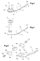
Figure 4 shows a side view of the probe element, the probe element support and the probe carrier ofFigure 1 , -
Figure 5 shows an exploded side view of the probe element, the probe element support and the probe carrier ofFigure 1 , -
Figure 6 shows an exploded perspective view of a probe element support and a probe carrier according to an alternative embodiment of the invention, and -
Figure 7 shows a perspective view of the testing arrangement ofFigure 1 that is embodied according to a second embodiment of the invention. -
Figure 1 shows atesting arrangement 1 for ultrasonic testing of a given mechanical component (e.g. 12 inFigure 7 ) by means of an associatedprobe element 2, according to a first embodiment of the present invention. Thetesting arrangement 1 preferably comprises aprobe carrier 1 a with aprobe element support 3, aleaf spring 4 and a carryingdevice 5. - The carrying
device 5 illustratively comprises a plate-shapedsection 5a and a rod-shapedsection 5b. The rod-shapedsection 5b is preferably embodied as a handle that can be gripped by a user for hand-guiding of thetesting arrangement 1. This rod-shapedsection 5b is, by way of example, provided with fixation means 6 that are illustratively arranged at an axial end of the rod-shapedsection 5b. The fixation means 6 can e.g. be used in order to attach the carryingdevice 5 to a testing machine or a testing roboter for an automated testing of the given mechanical component (e.g. 12 inFigure 7 ). - The plate-shaped
section 5a is, by way of example, provided at an axial end of the rod-shapedsection 5b that is opposite to the axial end bearing the fixation means 6. The plate-shapedsection 5a is rigidly attached to theleaf spring 4, e.g. by means of gluing, bonding and/or riveting. Preferably, however, the rigid attachment between the plate-shapedsection 5a and theleaf spring 4 is embodied as a releasable connection, e.g. as a screw connection. - The
leaf spring 4 preferably comprises at least one probe elementsupport attachment part 4a and a carryingdevice attachment part 4b, and is configured with a predetermined bending and torsional stiffness. The carryingdevice attachment part 4b is rigidly attached to the carryingdevice 5, i.e. its plate-shapedsection 5a, as described above. - The probe element
support attachment part 4a is preferably rigidly attached to theprobe element support 3 by means of an associatedsupport fixation 3a. Accordingly, theprobe element support 3 is rigidly attached to theleaf spring 4 and theprobe element support 3 and the carryingdevice 5 are, thus, interconnected by theleaf spring 4. The associatedsupport fixation 3a providing for the rigid attachment can e.g. be an adhesive or weld joint realized by means of gluing and/or bonding. - The
probe element support 3 is adapted to receive the associatedprobe element 2. Preferably, the associatedprobe element 2 is rigidly attached to theprobe element support 3 by means of an associatedprobe element fixation 2a. Accordingly, the associatedprobe element 2 is rigidly attached to theprobe element support 3. The associatedprobe element fixation 2a providing for the rigid attachment can e.g. be an adhesive or weld joint realized by means of gluing and/or bonding. - By way of example and not for limiting the invention accordingly, the associated
probe element 2 is embodied as a standard 5 MHz probe with a comparatively low diameter of approximately 6,35 mm. The associatedprobe element 2 is preferably connected to a suitable measuring station, e.g. by one or more suitable measurement cables. However, as suitable measuring stations and suitable measurement cables are well known by the person skilled in the art and are not part of the present invention, a detailed description and illustration of these elements has been omitted for brevity and conciseness of the description, and clarity and simplicity of the drawings. This also applies to all other figures and the following description. -
Figure 2 shows theprobe element 2, theprobe element support 3 and theleaf spring 4 ofFigure 1. Figure 2 further illustrates theleaf spring 4 with the probe elementsupport attachment part 4a and the carryingdevice attachment part 4b, both of which are by way of example represented as reinforced and at least slightly thicker sections of theleaf spring 4. - More specifically, the
leaf spring 4 is preferably embodied as a glassfiber leaf spring 7 that comprises a glass fiber laminate. Furthermore, at least the carryingdevice attachment part 4b can be embodied as a carbon fiber reinforcedsection 7a that is adapted for attachment to the carryingdevice 5 ofFigure 1 . Therefore, the carbon fiber reinforcedsection 7a illustratively comprises twoattachment openings support attachment part 4a for attachment of theprobe element support 3 can also be embodied as a carbon fiber reinforced section. - Preferably, the
probe element support 3 comprises acardanic bearing 8, which is preferentially embodied as a water resistant bearing. Thecardanic bearing 8 is configured to allow a required, predetermined number of degrees of freedom of theprobe element 2 in operation of thetesting arrangement 1 ofFigure 1 . -
Figure 3 shows theprobe element 2, theprobe element support 3 and the glassfiber leaf spring 7 ofFigure 2 for further illustration of the twoattachment openings section 7a. It should, however, be noted that these twoattachment openings fiber leaf spring 7 to the carryingdevice 5 ofFigure 1 . -
Figure 4 shows theprobe element 2, theprobe element support 3 and the glassfiber leaf spring 7 ofFigure 2 and Figure 3 for further illustration of a predefined inclination of the carbon fiber reinforcedsection 7a relative to the probe elementsupport attachment part 4a in order to generate a predefined spring load, as explained in more detail below with reference toFigure 7 . -
Figure 5 shows theprobe element 2, theprobe element support 3 and the glassfiber leaf spring 7 ofFigure 2 to Figure 4 for illustration of an exemplary assembling of these elements. Illustratively, the glassfiber leaf spring 7 comprises anattachment part opening 4e provided in its probe elementsupport attachment part 4a. - During assembly, the
probe element 2 is guided through theattachment part opening 4e of the glassfiber leaf spring 7. Then, theprobe element support 3 is rigidly attached to the glassfiber leaf spring 7 in the region of theattachment part opening 4e by means of thesupport fixation 3a ofFigure 1 . Subsequently, theprobe element 2 is rigidly attached to theprobe element support 3 by means of theprobe element fixation 2a ofFigure 1 . - It should be noted that the above described assembly process has only be explained by way of example, but not for limiting the invention accordingly. Instead, different assembly processes are possible and within the scope of the present invention. E.g. the
probe element 2 can be attached to theprobe element support 3 prior to attaching theprobe element support 3 to the glassfiber leaf spring 7, and so on. -
Figure 6 shows theprobe carrier 1a ofFigure 1 , which is now embodied according to an alternative embodiment. However, it should be noted that illustration of theprobe element 2 and the carryingdevice 5 ofFigure 1 has been omitted inFigure 6 for simplicity and clarity. - The
probe carrier 1 a according to the alternative embodiment illustratively comprises ametal leaf spring 13 having a probe elementsupport attachment part 13a and a carryingdevice attachment part 13b that are interconnected by a connectingpart 13c. Theparts support attachment part 13a and the carryingdevice attachment part 13b are realized as reinforced sections having e.g. a thicker cross section than the connectingpart 13c. - Preferably, the probe element
support attachment part 13a comprises a C- or U-shaped probeelement receiving recess 14 that is laterally delimited by corresponding lateralrecess leg portions recess leg portions ring support plates - The bearing
ring support plates support attachment part 13a. Each one of the bearingring support plates - The
borings ring rotation axles ring rotation axles bearing ring 18 to the bearingring support plates ring rotation axles - It should be noted that the
rotatable bearing ring 18 provides a smaller number of degrees of freedom as thecardanic bearing 8 ofFigure 2 to Figure 5 . However, theprobe carrier 1 a having therotatable bearing ring 18 can advantageously be applied for ultrasonic testing of mechanical components having only a planar or two-dimensionally shaped surface that is to be tested. -
Figure 7 shows thetesting arrangement 1 ofFigure 1 that is according to a second embodiment configured for use with aprobe element 11 having a comparatively large diameter of approximately 34 mm. In order to be able to cope with a corresponding, comparatively large weight of theprobe element 11, a plate-shapedleaf spring 9 is provided that preferably comprises Teflon. - The plate-shaped
leaf spring 9 comprises a mountingdevice attachment part 9a and a probeelement reception opening 9b. The mountingdevice attachment part 9a is preferably attached to an associated mountingdevice 10, which illustratively implements the carryingdevice 5 ofFigure 1 and which is preferably embodied for an automated ultrasonic testing of an associatedmechanical component 12. By way of example, the mountingdevice attachment part 9a is attached by means of a screw connection to the associated mountingdevice 10 in order to allow for an exchangeable configuration of thetesting arrangement 1. - The probe
element reception opening 9b is adapted for reception of theprobe element 11, which illustratively passes at least partially therethrough. Preferably, theopening 9b is configured such that theprobe element 11 is provided with similar degrees of freedom than theprobe element 2 inFigure 1 . - In operation of the
testing arrangement 1, theleaf spring 9 spring-loads theprobe element 11 against themechanical component 12, preferably with a restricted contact force, due to its geometrical embodiment, i.e. the inclination described by way of example with respect to the glassfiber leaf spring 7 above. Thus, a safe and reliable ultrasonic inspection of themechanical component 12 can be performed. - It should be noted that the
leaf springs 4 ofFigure 1 to Figure 4 and 13 ofFigure 6 operate similarly. Therefore, illustration of corresponding operation modes as well as a detailed description thereof is omitted for brevity and conciseness. This also applies to a complete measurement procedure, which is well-known to the person skilled in the art and not part of the present invention. - Using the leaf spring configurations according to the present invention, comparatively thin mechanical components can be subjected to ultrasonic testing. For instance, monolithic components with a thickness of approximately 1 mm were experimentally tested using the pulse-echo method.
-
- 1
- testing arrangement
- 1a
- probe carrier
- 2
- lower diameter probe element
- 2a
- probe element fixation
- 3
- probe element support
- 3a
- support fixation
- 4
- plastic leaf spring
- 4a
- probe element support attachment part
- 4b
- carrying device attachment part
- 4c, 4d
- attachment openings
- 4e
- attachment part opening
- 5
- carrying device
- 5a
- plate-shaped section
- 5b
- rod-shaped section
- 6
- fixation means
- 7
- glass fiber leaf spring
- 7a
- carbon fiber reinforced section
- 8
- cardanic bearing
- 9
- teflon leaf spring
- 9a
- mounting device attachment part
- 9b
- probe element reception opening
- 10
- mounting device
- 11
- large diameter probe element
- 12
- mechanical component
- 13
- metal leaf spring
- 13a
- probe element support attachment part
- 13b
- carrying device attachment part
- 13c
- connecting part
- 14
- probe element receiving recess
- 14a, 14b
- lateral recess leg portions
- 15a, 15b
- bearing ring support plates
- 16a, 16b
- support plate openings
- 17a, 17b
- bearing ring rotation axles
- 18
- bearing ring
Claims (15)
- A testing arrangement (1) for ultrasonic testing of a mechanical component (12) by means of an associated probe element (2), comprising a probe carrier (1a) with a carrying device (5) and a probe element support (3), said probe element support (3) being adapted to receive said associated probe element (2), wherein said probe element support (3) and said carrying device (5) are interconnected by a leaf spring (4).
- The testing arrangement (1) according to claim 1,
characterized in that said leaf spring (4) comprises a probe element support attachment part (4a) that is rigidly attached to said probe element support (3), and a carrying device attachment part (4b) that is rigidly attached to said carrying device (5). - The testing arrangement (1) according to claim 2,
characterized in that said carrying device (5) comprises a plate-shaped section (5a) to which said leaf spring (4) is rigidly attached. - The testing arrangement (1) according to claim 3,
characterized in that said leaf spring (4) is rigidly attached to said plate-shaped section (5a) by means of gluing, bonding, riveting and/or screwing. - The testing arrangement (1) according to claim 2,
characterized in that said leaf spring (4) is rigidly attached to said probe element support (3) by means of gluing and/or bonding. - The testing arrangement (1) according to claim 1, characterized in that said probe element support (3) comprises a cardanic bearing (8).
- The testing arrangement (1) according to claim 6,
characterized in that said cardanic bearing (8) is a water resistant bearing. - The testing arrangement (1) according to claim 1,
characterized in that said leaf spring (4) comprises a glass fiber laminate. - The testing arrangement (1) according to claim 8,
characterized in that said leaf spring (4) comprises a carbon fiber reinforced section (7a). - The testing arrangement (1) according to claim 9,
characterized in that said carbon fiber reinforced section (7a) is adapted for attachment to the carrying device (5). - The testing arrangement (1) according to claim 1,
characterized in that said leaf spring (4) comprises Teflon. - The testing arrangement (1) according to claim 11,
characterized in that said leaf spring (4) is plate-shaped and comprises an opening (9b) for reception of said associated probe element (11). - The testing arrangement (1) according to claim 1,
characterized in that said leaf spring (4) is adapted to spring-load said associated probe element (2) against said mechanical component (12) in operation of said testing arrangement (1). - The testing arrangement (1) according to claim 13,
characterized in that said leaf spring (4) is adapted to spring-load said associated probe element (2) against said mechanical component (12) in operation of said testing arrangement (1) with a restricted contact force. - The testing arrangement (1) according to claim 1,
characterized in that said leaf spring (4) comprises a predetermined bending and torsional stiffness.
Priority Applications (1)
| Application Number | Priority Date | Filing Date | Title |
|---|---|---|---|
| EP14400010.6A EP2910942A1 (en) | 2014-02-24 | 2014-02-24 | Testing arrangement for ultrasonic testing of a mechanical component |
Applications Claiming Priority (1)
| Application Number | Priority Date | Filing Date | Title |
|---|---|---|---|
| EP14400010.6A EP2910942A1 (en) | 2014-02-24 | 2014-02-24 | Testing arrangement for ultrasonic testing of a mechanical component |
Publications (1)
| Publication Number | Publication Date |
|---|---|
| EP2910942A1 true EP2910942A1 (en) | 2015-08-26 |
Family
ID=50624537
Family Applications (1)
| Application Number | Title | Priority Date | Filing Date |
|---|---|---|---|
| EP14400010.6A Withdrawn EP2910942A1 (en) | 2014-02-24 | 2014-02-24 | Testing arrangement for ultrasonic testing of a mechanical component |
Country Status (1)
| Country | Link |
|---|---|
| EP (1) | EP2910942A1 (en) |
Citations (6)
| Publication number | Priority date | Publication date | Assignee | Title |
|---|---|---|---|---|
| US4030370A (en) * | 1976-02-25 | 1977-06-21 | Continental Oil Company | Transducer positioner for testing tubes from inside diameter |
| DE2916149A1 (en) * | 1978-08-30 | 1980-03-13 | Picker Corp | DRIVE SYSTEM FOR THE TRANSMITTER OF A REAL-TIME SCANNING ULTRASONIC IMAGING SYSTEM |
| DE2935497A1 (en) * | 1979-09-03 | 1981-03-19 | Siemens AG, 1000 Berlin und 8000 München | Ultrasonic test head for surface measurements - has spring-loaded guide with linkage for reduced bending load |
| DE19803266A1 (en) * | 1998-01-29 | 1999-08-05 | Wolfgang Stepanow | Mounting for swivel-head ultrasonic transmitter and receiver transducers |
| CN201464432U (en) | 2009-08-07 | 2010-05-12 | 北京有色金属研究总院 | Ultrasonic flaw detection probe tracking device |
| JP2011252759A (en) * | 2010-06-01 | 2011-12-15 | Mitsubishi Heavy Ind Ltd | Ultrasonic flaw detection system |
-
2014
- 2014-02-24 EP EP14400010.6A patent/EP2910942A1/en not_active Withdrawn
Patent Citations (6)
| Publication number | Priority date | Publication date | Assignee | Title |
|---|---|---|---|---|
| US4030370A (en) * | 1976-02-25 | 1977-06-21 | Continental Oil Company | Transducer positioner for testing tubes from inside diameter |
| DE2916149A1 (en) * | 1978-08-30 | 1980-03-13 | Picker Corp | DRIVE SYSTEM FOR THE TRANSMITTER OF A REAL-TIME SCANNING ULTRASONIC IMAGING SYSTEM |
| DE2935497A1 (en) * | 1979-09-03 | 1981-03-19 | Siemens AG, 1000 Berlin und 8000 München | Ultrasonic test head for surface measurements - has spring-loaded guide with linkage for reduced bending load |
| DE19803266A1 (en) * | 1998-01-29 | 1999-08-05 | Wolfgang Stepanow | Mounting for swivel-head ultrasonic transmitter and receiver transducers |
| CN201464432U (en) | 2009-08-07 | 2010-05-12 | 北京有色金属研究总院 | Ultrasonic flaw detection probe tracking device |
| JP2011252759A (en) * | 2010-06-01 | 2011-12-15 | Mitsubishi Heavy Ind Ltd | Ultrasonic flaw detection system |
Similar Documents
| Publication | Publication Date | Title |
|---|---|---|
| JP6010733B2 (en) | Plate-shaped specimen evaluation test unit and fixing jig used therefor | |
| US9677982B2 (en) | Jig mounting device for material testing machine | |
| US20120006236A1 (en) | Adhesive holder for holding objects and kit, as well as method for making an adhesive holder | |
| JPH0339627B2 (en) | ||
| CN106168556B (en) | A kind of anti-unstability device tested for docking wall strength | |
| EP2752650A1 (en) | Force sensor and robot | |
| US10866175B2 (en) | Self contained load frame for in-situ inspection | |
| US20150040680A1 (en) | Circumferential shear test method and apparatus for a sandwich structure | |
| EP2781764A1 (en) | Device for testing out-of-plane tensile strength and method of testing of out-of-plane tensile strength of a load application element fitted to a composite sandwich panel | |
| KR20150137187A (en) | Apparatus and method for aligning with a test specimen | |
| EP2352616B1 (en) | Method and device for force-fit connecting glass-like components to metals | |
| EP2495544B1 (en) | Short Beam Shear Test Fixture | |
| JP2015079221A (en) | Optical element support device and method for adjusting optical element support device | |
| KR20140026754A (en) | A bending angle measuring device for bending tube | |
| JP6299633B2 (en) | Axis adjusting device and material testing machine | |
| MX2012005490A (en) | Holder frame. | |
| US10737349B2 (en) | Measuring device for automated welding devices, in particular for robot welding tongs | |
| JP5375771B2 (en) | Axis adjuster for material testing machine | |
| EP2805793B1 (en) | Guide frame support device | |
| CN107907333B (en) | Cylindrical elastic bearing fatigue test device | |
| CN112284699B (en) | Dynamic loading torsion test device and dynamic loading torsion test method | |
| CN104062187B (en) | Insulator torsion resistant and bending resistant assay device | |
| CN109506915A (en) | A kind of tail-rotor steering assembly fatigue experimental device | |
| KR101081553B1 (en) | Tension and compression coupon tester using four-bar linkage | |
| CN209802224U (en) | Novel detection tool for detection and correction among parts of instrument board beam assembly |
Legal Events
| Date | Code | Title | Description |
|---|---|---|---|
| PUAI | Public reference made under article 153(3) epc to a published international application that has entered the european phase |
Free format text: ORIGINAL CODE: 0009012 |
|
| AK | Designated contracting states |
Kind code of ref document: A1 Designated state(s): AL AT BE BG CH CY CZ DE DK EE ES FI FR GB GR HR HU IE IS IT LI LT LU LV MC MK MT NL NO PL PT RO RS SE SI SK SM TR |
|
| AX | Request for extension of the european patent |
Extension state: BA ME |
|
| RIN1 | Information on inventor provided before grant (corrected) |
Inventor name: BLUDAU, JAKOB Inventor name: HOLZHEIMER, MANUEL |
|
| 17P | Request for examination filed |
Effective date: 20151012 |
|
| RBV | Designated contracting states (corrected) |
Designated state(s): AL AT BE BG CH CY CZ DE DK EE ES FI FR GB GR HR HU IE IS IT LI LT LU LV MC MK MT NL NO PL PT RO RS SE SI SK SM TR |
|
| STAA | Information on the status of an ep patent application or granted ep patent |
Free format text: STATUS: THE APPLICATION IS DEEMED TO BE WITHDRAWN |
|
| 18D | Application deemed to be withdrawn |
Effective date: 20190903 |