EP2910769A1 - Fuel pumping mechanism - Google Patents
Fuel pumping mechanism Download PDFInfo
- Publication number
- EP2910769A1 EP2910769A1 EP14156469.0A EP14156469A EP2910769A1 EP 2910769 A1 EP2910769 A1 EP 2910769A1 EP 14156469 A EP14156469 A EP 14156469A EP 2910769 A1 EP2910769 A1 EP 2910769A1
- Authority
- EP
- European Patent Office
- Prior art keywords
- intermediate member
- pumping
- contact surface
- tappet
- plunger
- Prior art date
- Legal status (The legal status is an assumption and is not a legal conclusion. Google has not performed a legal analysis and makes no representation as to the accuracy of the status listed.)
- Withdrawn
Links
- 238000005086 pumping Methods 0.000 title claims abstract description 82
- 239000000446 fuel Substances 0.000 title claims abstract description 17
- 238000002485 combustion reaction Methods 0.000 claims abstract description 7
- 239000000463 material Substances 0.000 description 3
- 241001416181 Axis axis Species 0.000 description 2
- 230000003466 anti-cipated effect Effects 0.000 description 1
- 238000003754 machining Methods 0.000 description 1
Images


Classifications
-
- F—MECHANICAL ENGINEERING; LIGHTING; HEATING; WEAPONS; BLASTING
- F02—COMBUSTION ENGINES; HOT-GAS OR COMBUSTION-PRODUCT ENGINE PLANTS
- F02M—SUPPLYING COMBUSTION ENGINES IN GENERAL WITH COMBUSTIBLE MIXTURES OR CONSTITUENTS THEREOF
- F02M59/00—Pumps specially adapted for fuel-injection and not provided for in groups F02M39/00 -F02M57/00, e.g. rotary cylinder-block type of pumps
- F02M59/02—Pumps specially adapted for fuel-injection and not provided for in groups F02M39/00 -F02M57/00, e.g. rotary cylinder-block type of pumps of reciprocating-piston or reciprocating-cylinder type
- F02M59/10—Pumps specially adapted for fuel-injection and not provided for in groups F02M39/00 -F02M57/00, e.g. rotary cylinder-block type of pumps of reciprocating-piston or reciprocating-cylinder type characterised by the piston-drive
- F02M59/102—Mechanical drive, e.g. tappets or cams
-
- F—MECHANICAL ENGINEERING; LIGHTING; HEATING; WEAPONS; BLASTING
- F04—POSITIVE - DISPLACEMENT MACHINES FOR LIQUIDS; PUMPS FOR LIQUIDS OR ELASTIC FLUIDS
- F04B—POSITIVE-DISPLACEMENT MACHINES FOR LIQUIDS; PUMPS
- F04B1/00—Multi-cylinder machines or pumps characterised by number or arrangement of cylinders
- F04B1/12—Multi-cylinder machines or pumps characterised by number or arrangement of cylinders having cylinder axes coaxial with, or parallel or inclined to, main shaft axis
- F04B1/14—Multi-cylinder machines or pumps characterised by number or arrangement of cylinders having cylinder axes coaxial with, or parallel or inclined to, main shaft axis having stationary cylinders
-
- F—MECHANICAL ENGINEERING; LIGHTING; HEATING; WEAPONS; BLASTING
- F04—POSITIVE - DISPLACEMENT MACHINES FOR LIQUIDS; PUMPS FOR LIQUIDS OR ELASTIC FLUIDS
- F04B—POSITIVE-DISPLACEMENT MACHINES FOR LIQUIDS; PUMPS
- F04B9/00—Piston machines or pumps characterised by the driving or driven means to or from their working members
- F04B9/02—Piston machines or pumps characterised by the driving or driven means to or from their working members the means being mechanical
- F04B9/04—Piston machines or pumps characterised by the driving or driven means to or from their working members the means being mechanical the means being cams, eccentrics or pin-and-slot mechanisms
Definitions
- the present invention relates to a fuel pump for use in an internal combustion engine, and more particularly to an improved pumping mechanism for a fuel pump having at least one pumping element which is driven by an engine-driven cam or other appropriate drive arrangement.
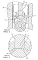
- FIG. 1 is a cross-sectional partial view of a pumping mechanism in accordance with the prior art.
- a common pumping mechanism 100 for a fuel pump for an internal combustion engine comprises a pump housing 102, containing a pumping element location bore 120 in which a pumping element such as a plunger 114 is moveable.
- a first end (not shown) of the plunger 114 extends into a pumping chamber (not shown) defined at one end of the pumping element location bore 120.
- the pumping mechanism 100 further comprises a driving mechanism such as a cam roller 110, and an intermediate member such as a follower or tappet 112, which is moveable within an intermediate member location bore 122.
- the plunger 114 is urged further into the pumping element location bore 120, by a driving force applied by the cam roller 110.
- load is transferred from the cam roller 110 to the plunger 114 via a contact surface 116 provided on the tappet 112, and a contact surface 118 provided at a second end 128 of the plunger 114.
- the plunger 114 is urged into the pumping chamber by the cam load, thereby reducing the volume of the pumping chamber, causing fuel in the pumping chamber to become pressurised.
- the contact surface 116 of the tappet 112 would make a flat, even contact with a flat contact surface 118 of the plunger 114.
- the axes of the plunger 114 and tappet 112 within their respective location bores are usually misaligned, due to geometry errors and clearances.
- the tappet will usually be caused to tilt within the tappet location bore 122 at an angle relative to the cam load.
- the radius provided on the plunger 112 must be selected in accordance with the anticipated misalignment of the axis of the tappet 114 from the axis of the tappet location bore 122. It is preferable for the radius provided on the plunger 112 to be large, thereby ensuring that contact (Hertzian) stresses are maintained within the capability of the materials. However, if the radius is too large, edge contact will occur when the tappet 112 is tilted within the tappet location bore 122. Accordingly, selection of a sufficiently large radius for the end of the pumping element is constrained by the requirement to avoid edge contact and resulting high point stresses.
- FIGS 2 and 3 are enlarged cross-sectional partial views of the prior art pumping mechanism of Figure 1 .
- the tappet contact surface 116 contacts the plunger contact surface 118 during the pumping stroke at a contact point, indicated generally at 130. As illustrated, even with a radiused end of plunger 112, the contact point 130 occurs towards to a side portion of the contact surfaces 116, 118.
- the present invention provides, in a first aspect, a pumping mechanism for a fuel pump according to claim 1.
- the intermediate member is usually caused to tilt to a known angle.
- the intermediate member contact surface is angled with respect to the axial axis of the intermediate member to this known angle, such that during the pumping stroke, the intermediate member contact surface is orthogonal with the longitudinal axis of the intermediate member location bore.
- Selecting the angle A of the tappet contact surface in accordance with the predictable tilt of the tappet within the tappet bore during the pumping stroke ensures that the nominal contact between the contact surfaces occurs substantially at the centre of each contact surface, thereby avoiding edge contact.
- the present invention allows a larger degree of tilt of the tappet within the tappet location bore, or allows a larger radius to be provided on the plunger. Contact stresses are thereby maintained within the capabilities of the materials providing greater durability, or the possibility of higher pressure running, than prior art embodiments.
- the second end of the pumping element is preferably radiused, thereby providing an arcuate pumping element contact surface.
- the present invention also provides, in a further aspect, a tappet for use in a pumping mechanism of a fuel pump, according to claim 4, and a fuel pump according to claim 5.
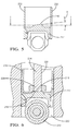
- the present invention comprises a pumping mechanism 200 comprising a pump housing 202.
- the pump housing 202 comprises a plunger location bore 220 for locating a pumping element in the form of a plunger 214, a driving mechanism comprising a cam roller 210, and an intermediate member comprising a tappet 212 located in a tappet location bore 222.
- the plunger location bore 220 defines a pumping chamber 224 at one end, into which a first end 226 of the plunger 214 extends.
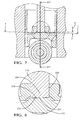
- the tappet 212 is provided with a tappet contact surface 216, for contacting with a plunger contact surface 218 ( Figure 6 ) provided at a second end 228 of the plunger 214 remote from the first end 226.
- the figures represent a pumping stroke, wherein the tappet contact surface 216 is in contact with the plunger contact surface 218, i.e. load from the cam roller 210 is being imparted to contact surface 218 of the plunger 214 via the contact surface 216 of the tappet 212. Consequently, the plunger 214 is being urged further into the plunger location bore 220 by the cam load, thereby causing fuel in the pumping chamber 224 to become pressurised.
- the tappet location bore 220 has a longitudinal axis B, and the plunger 214 has a longitudinal axis P.
- the clearance between the plunger 214 and the plunger location bore 220 is minimal, therefore any tilting of the plunger P within the plunger location bore 220 is negligible. Therefore, the longitudinal axis B of the tappet location bore 222 is substantially coincident with the longitudinal axis P of the plunger 214.
- the second end 228 of the plunger 214 is radiused, such that the plunger contact surface 218 is arcuate.
- the tappet contact surface 216 is substantially flat, and is angled at an angle A with respect to an axial axis T of the tappet (wherein axis T is perpendicular to an external wall 232 of the tappet 212, as indicated in Figure 5 ).
- the axial axis T of the tappet is orthogonal to the axis B of the tappet location bore 222 and the axis P of the plunger.
- the tappet 212 is caused to tilt within the tappet location bore 222, to an angle A.
- the axial axis T of the tappet is no longer orthogonal with the axis B of the tappet location bore 222.
- the direction and degree A of tilt of the tappet 212 within the tappet location bore 222 is consistent in each pumping stroke for a nominal clearance, i.e. the direction and angle of tilt A can be predicted for a given fuel pump for a nominal clearance.
- the direction of tilt, and the angle of the tappet contact surface 216 is selected in accordance with the predicable tilt of the tappet 212 during the pumping stroke, i.e.
- the tappet contact surface 216 is angled at angle A to the axial axis T of the tappet 212, such that when the tappet 212 is in the tilted position, the angled tappet contact surface 216 is orthogonal with the axis B of the tappet location bore 222.
- a nominal contact point (most clearly indicated in Figure 8 , at approximately point 230)
- the plunger contact surface 218 occurs substantially at the centre of the plunger contact surface 216, thereby avoiding high point stresses which would result from edge contact. Allowing a larger radius to be provided on the plunger 214 ensures that contact stresses are maintained within the capabilities of the materials, or allows the pumping mechanism to be run at higher pressures.
Landscapes
- Engineering & Computer Science (AREA)
- Mechanical Engineering (AREA)
- General Engineering & Computer Science (AREA)
- Chemical & Material Sciences (AREA)
- Combustion & Propulsion (AREA)
- Fuel-Injection Apparatus (AREA)
Abstract
Internal combustion engine fuel pumping mechanism (200), comprising a pumping element (214) such as a plunger, moveable within first location bore, an intermediate member such as a tappet, movable within a second location bore, and a driving mechanism such as a cam, wherein during a pumping stroke, cam load is transferred to the plunger via contact surfaces plunger and tappet contact surfaces, the plunger contact surface being radiused, and the tappet contact surface being angled at a selected angle with respect to an axial axis of the tappet, such that when the tappet tilts within the second location bore on application of cam load, the tappet contact surface becomes orthogonal with a longitudinal axis of the second bore and the plunger, ensuring a substantially central contact point between the contact surfaces. The inventive concept also extends to an intermediate member comprising a contact surface which is angled with respect to an axial axis of the intermediate member.
Description
- The present invention relates to a fuel pump for use in an internal combustion engine, and more particularly to an improved pumping mechanism for a fuel pump having at least one pumping element which is driven by an engine-driven cam or other appropriate drive arrangement.
-
Figure 1 is a cross-sectional partial view of a pumping mechanism in accordance with the prior art. As illustrated in this figure, acommon pumping mechanism 100 for a fuel pump for an internal combustion engine comprises apump housing 102, containing a pumping element location bore 120 in which a pumping element such as aplunger 114 is moveable. A first end (not shown) of theplunger 114 extends into a pumping chamber (not shown) defined at one end of the pumping element location bore 120. Thepumping mechanism 100 further comprises a driving mechanism such as acam roller 110, and an intermediate member such as a follower ortappet 112, which is moveable within an intermediate member location bore 122. - During a pumping stroke, the
plunger 114 is urged further into the pumpingelement location bore 120, by a driving force applied by thecam roller 110. On rotation of thecam roller 110, load is transferred from thecam roller 110 to theplunger 114 via acontact surface 116 provided on thetappet 112, and acontact surface 118 provided at asecond end 128 of theplunger 114. Theplunger 114 is urged into the pumping chamber by the cam load, thereby reducing the volume of the pumping chamber, causing fuel in the pumping chamber to become pressurised. - It is important that the very high forces which are transferred via the
contact surfaces - Ideally, the
contact surface 116 of thetappet 112 would make a flat, even contact with aflat contact surface 118 of theplunger 114. In practice, however, the axes of theplunger 114 and tappet 112 within their respective location bores are usually misaligned, due to geometry errors and clearances. For example, on application of cam load, the tappet will usually be caused to tilt within the tappet location bore 122 at an angle relative to the cam load. Therefore if thecontact surfaces plunger 114 andtappet 112 were both flat, the misalignment of the axes of theplunger 114 and thetilted tappet 112 would result in substantially all cam load being transferred to an edge of theplunger contact surface 118, resulting in high point stresses at this edge. Accordingly, it is common for a radius to be provided on the end of theplunger 112, i.e. for thecontact surface 118 of theplunger 112 to be arcuate. - The radius provided on the
plunger 112 must be selected in accordance with the anticipated misalignment of the axis of thetappet 114 from the axis of the tappet location bore 122. It is preferable for the radius provided on theplunger 112 to be large, thereby ensuring that contact (Hertzian) stresses are maintained within the capability of the materials. However, if the radius is too large, edge contact will occur when thetappet 112 is tilted within the tappet location bore 122. Accordingly, selection of a sufficiently large radius for the end of the pumping element is constrained by the requirement to avoid edge contact and resulting high point stresses. -
Figures 2 and 3 are enlarged cross-sectional partial views of the prior art pumping mechanism ofFigure 1 . Thetappet contact surface 116 contacts theplunger contact surface 118 during the pumping stroke at a contact point, indicated generally at 130. As illustrated, even with a radiused end ofplunger 112, thecontact point 130 occurs towards to a side portion of thecontact surfaces - It is an object of the present invention to at least mitigate the above problems and provide an improved pumping mechanism for an internal combustion engine.
- Accordingly the present invention provides, in a first aspect, a pumping mechanism for a fuel pump according to claim 1.
- The intermediate member is usually caused to tilt to a known angle. Preferably, the intermediate member contact surface is angled with respect to the axial axis of the intermediate member to this known angle, such that during the pumping stroke, the intermediate member contact surface is orthogonal with the longitudinal axis of the intermediate member location bore.
- Selecting the angle A of the tappet contact surface in accordance with the predictable tilt of the tappet within the tappet bore during the pumping stroke ensures that the nominal contact between the contact surfaces occurs substantially at the centre of each contact surface, thereby avoiding edge contact. The present invention allows a larger degree of tilt of the tappet within the tappet location bore, or allows a larger radius to be provided on the plunger. Contact stresses are thereby maintained within the capabilities of the materials providing greater durability, or the possibility of higher pressure running, than prior art embodiments.
- The second end of the pumping element is preferably radiused, thereby providing an arcuate pumping element contact surface.
- The present invention also provides, in a further aspect, a tappet for use in a pumping mechanism of a fuel pump, according to claim 4, and a fuel pump according to claim 5.
- The present invention is now described by way of example with reference to the accompanying drawings in which:
-
Figure 4 is a cross-sectional view of a pumping mechanism in accordance with the present invention taken along a longitudinal axis of the cam, -
Figure 5 is a cross-sectional view of a tappet ofFigure 4 taken along an axial axis of the cam;
and -
Figures 6 ,7 and 8 are partial cross-sectional views of the pumping mechanism ofFigure 3 taken along an axial axis of the cam. - Referring to
Figure 4 , the present invention comprises apumping mechanism 200 comprising a pump housing 202. The pump housing 202 comprises aplunger location bore 220 for locating a pumping element in the form of aplunger 214, a driving mechanism comprising acam roller 210, and an intermediate member comprising atappet 212 located in atappet location bore 222. - The
plunger location bore 220 defines apumping chamber 224 at one end, into which afirst end 226 of theplunger 214 extends. - As indicated in
Figures 6 and8 , thetappet 212 is provided with atappet contact surface 216, for contacting with a plunger contact surface 218 (Figure 6 ) provided at asecond end 228 of theplunger 214 remote from thefirst end 226. The figures represent a pumping stroke, wherein thetappet contact surface 216 is in contact with theplunger contact surface 218, i.e. load from thecam roller 210 is being imparted to contactsurface 218 of theplunger 214 via thecontact surface 216 of thetappet 212. Consequently, theplunger 214 is being urged further into the plunger location bore 220 by the cam load, thereby causing fuel in thepumping chamber 224 to become pressurised. - As indicated in
Figures 4 and7 , thetappet location bore 220 has a longitudinal axis B, and theplunger 214 has a longitudinal axis P. Although minor tolerance errors may occur in the machining of the plunger location bore 220, the clearance between theplunger 214 and theplunger location bore 220 is minimal, therefore any tilting of the plunger P within theplunger location bore 220 is negligible. Therefore, the longitudinal axis B of thetappet location bore 222 is substantially coincident with the longitudinal axis P of theplunger 214. - The
second end 228 of theplunger 214 is radiused, such that theplunger contact surface 218 is arcuate. Thetappet contact surface 216 is substantially flat, and is angled at an angle A with respect to an axial axis T of the tappet (wherein axis T is perpendicular to anexternal wall 232 of thetappet 212, as indicated inFigure 5 ). - Before application of force from the
cam roller 210 to thetappet 212, the axial axis T of the tappet is orthogonal to the axis B of the tappet location bore 222 and the axis P of the plunger. As shown inFigures 6 and7 , on application of the cam load, i.e. during the pumping stroke, thetappet 212 is caused to tilt within thetappet location bore 222, to an angle A. At this tilted position, the axial axis T of the tappet is no longer orthogonal with the axis B of the tappet location bore 222. - The direction and degree A of tilt of the
tappet 212 within thetappet location bore 222 is consistent in each pumping stroke for a nominal clearance, i.e. the direction and angle of tilt A can be predicted for a given fuel pump for a nominal clearance. The direction of tilt, and the angle of the tappet contact surface 216 (with respect to the axial axis T of the tappet), is selected in accordance with the predicable tilt of thetappet 212 during the pumping stroke, i.e. thetappet contact surface 216 is angled at angle A to the axial axis T of thetappet 212, such that when thetappet 212 is in the tilted position, the angledtappet contact surface 216 is orthogonal with the axis B of the tappet location bore 222. As a result, when thetappet 212 is tilted, a nominal contact point, (most clearly indicated inFigure 8 , at approximately point 230), between thetappet contact surface 216 and theplunger contact surface 218 occurs substantially at the centre of theplunger contact surface 216, thereby avoiding high point stresses which would result from edge contact. Allowing a larger radius to be provided on theplunger 214 ensures that contact stresses are maintained within the capabilities of the materials, or allows the pumping mechanism to be run at higher pressures. -
- 100, 200
- pumping mechanism
- 102, 202
- pump housing
- 110, 210
- driving mechanism (cam)
- 112, 212
- intermediate member (tappet)
- 114, 214
- pumping element (plunger)
- 116, 216
- intermediate member (tappet) contact surface
- 118, 218
- pumping element (plunger) contact surface
- 120, 220
- pumping element (plunger) location bore
- 122, 222
- intermediate member (tappet) location bore
- 224
- pumping chamber
- 226
- plunger first end
- 128, 228
- plunger second end
- 130, 230
- contact point
- 232
- tappet external wall
- Angle A
- tappet surface angle
- Axis B
- tappet location bore longitudinal axis
- Axis P
- plunger longitudinal axis
- Axis T
- tappet axial axis
Claims (5)
- A pumping mechanism (200) for a fuel pump for use in an internal combustion engine, the pumping mechanism (200) comprising:a pumping element location bore (220) for locating a pumping element (214), an intermediate member location bore (222) for locating an intermediate member (212),wherein the intermediate member (212) is co-operable with a driving mechanism (210),wherein the pumping element (214) is moveable within and along a longitudinal axis (B) of the pumping element location bore (220), to pressurise fuel within a pumping chamber (224) adjacent a first end (226) of the pumping element (214) during a pumping stroke;the intermediate member (212) being movable within the intermediate member location bore (222);wherein the intermediate member (212) comprises an intermediate member contact surface (216), for contacting a pumping element contact surface (218) located at a second end (228) of the pumping element (214) remote from the first end (226), thereby to transfer load from the driving mechanism (210) to the pumping element (214) during the pumping stroke;characterised in that the intermediate member contact surface (216) is angled with respect to an axial axis (T) of the intermediate member (212).
- A pumping mechanism (200) as claimed in claim 1 wherein, during the pumping stroke, the intermediate member (212) is caused to tilt within the intermediate member location bore (222) to a known angle (A), and wherein the intermediate member contact surface (216) is angled with respect to the axial axis (T) of the intermediate member (212) to the known angle (A), such that during the pumping stroke, the intermediate member contact surface (216) is orthogonal with the longitudinal axis (B) of the intermediate member location bore (222).
- A pumping mechanism (200) as claimed in any one of the preceding claims wherein the second end (228) of the pumping element (214) is radiused thereby providing an arcuate pumping element contact surface (218).
- An intermediate member (212) for a pumping mechanism (200) of a fuel pump for an internal combustion engine;
the intermediate member (212) having an intermediate member contact surface (216) for imparting drive from a driving mechanism (210) to a pumping element contact surface (218) provided on a pumping element (214), thereby to urge the pumping element (214) into a pumping chamber (224) to pressurise fuel contained in the pumping chamber (224),
wherein the intermediate member contact surface (216) is angled with respect to an axial axis (T) of the intermediate member (212) perpendicular to an external wall (232) of the intermediate member (212). - A fuel pump for an internal combustion engine comprising at least one pumping mechanism (200),
the at least one pumping mechanism (200) comprising a pumping element location bore (220) for locating a pumping element (214), an intermediate member location bore (222) for locating an intermediate member (212),
wherein the intermediate member (212) is co-operable with a driving mechanism (210),
wherein the pumping element (214) is moveable within and along a longitudinal axis (B) of the pumping element location bore (220), to pressurise fuel within a pumping chamber (224) adjacent a first end (226) of the pumping element (214) during a pumping stroke;
the intermediate member (212) being movable within the intermediate member location bore (222);
wherein the intermediate member (212) comprises an intermediate member contact surface (216), for contacting a pumping element contact surface (218) located at a second end (228) of the pumping element (214) remote from the first end (226), thereby to transfer load from the driving mechanism (210) to the pumping element (214) during the pumping stroke;
characterised in that the intermediate member contact surface (216) is angled with respect to an axial axis (T) of the intermediate member (212).
Priority Applications (5)
| Application Number | Priority Date | Filing Date | Title |
|---|---|---|---|
| EP14156469.0A EP2910769A1 (en) | 2014-02-25 | 2014-02-25 | Fuel pumping mechanism |
| CN201580009926.XA CN106103969B (en) | 2014-02-25 | 2015-01-26 | Fuel pumping mechanism |
| EP15702207.0A EP3111080B1 (en) | 2014-02-25 | 2015-01-26 | Fuel pumping mechanism |
| KR1020167023161A KR102156134B1 (en) | 2014-02-25 | 2015-01-26 | Fuel pumping mechanism |
| PCT/EP2015/051453 WO2015128133A1 (en) | 2014-02-25 | 2015-01-26 | Fuel pumping mechanism |
Applications Claiming Priority (1)
| Application Number | Priority Date | Filing Date | Title |
|---|---|---|---|
| EP14156469.0A EP2910769A1 (en) | 2014-02-25 | 2014-02-25 | Fuel pumping mechanism |
Publications (1)
| Publication Number | Publication Date |
|---|---|
| EP2910769A1 true EP2910769A1 (en) | 2015-08-26 |
Family
ID=50190234
Family Applications (2)
| Application Number | Title | Priority Date | Filing Date |
|---|---|---|---|
| EP14156469.0A Withdrawn EP2910769A1 (en) | 2014-02-25 | 2014-02-25 | Fuel pumping mechanism |
| EP15702207.0A Active EP3111080B1 (en) | 2014-02-25 | 2015-01-26 | Fuel pumping mechanism |
Family Applications After (1)
| Application Number | Title | Priority Date | Filing Date |
|---|---|---|---|
| EP15702207.0A Active EP3111080B1 (en) | 2014-02-25 | 2015-01-26 | Fuel pumping mechanism |
Country Status (4)
| Country | Link |
|---|---|
| EP (2) | EP2910769A1 (en) |
| KR (1) | KR102156134B1 (en) |
| CN (1) | CN106103969B (en) |
| WO (1) | WO2015128133A1 (en) |
Cited By (1)
| Publication number | Priority date | Publication date | Assignee | Title |
|---|---|---|---|---|
| GB2543354A (en) * | 2015-10-16 | 2017-04-19 | Gm Global Tech Operations Llc | Roller tappet for a fuel unit pump of an internal combustion engine |
Families Citing this family (1)
| Publication number | Priority date | Publication date | Assignee | Title |
|---|---|---|---|---|
| DE102020106409A1 (en) * | 2020-03-10 | 2021-09-16 | Schaeffler Technologies AG & Co. KG | Roller tappet for a high pressure fuel pump |
Citations (4)
| Publication number | Priority date | Publication date | Assignee | Title |
|---|---|---|---|---|
| EP1347172A2 (en) * | 2002-03-21 | 2003-09-24 | DaimlerChrysler AG | Piston pump |
| DE102006045933A1 (en) * | 2006-09-28 | 2008-04-03 | Robert Bosch Gmbh | Plunger assembly for a high pressure pump and high pressure pump with at least one plunger assembly |
| DE102007022220A1 (en) * | 2007-05-11 | 2008-11-13 | Robert Bosch Gmbh | High-pressure pump for combustion engine fuel system, has tappet floor and piston coupled via first and second coupling sections |
| WO2013117485A1 (en) * | 2012-02-09 | 2013-08-15 | Delphi Technologies Holding S.À.R.L. | Improvements relating to fuel pumps |
Family Cites Families (3)
| Publication number | Priority date | Publication date | Assignee | Title |
|---|---|---|---|---|
| US4771676A (en) * | 1986-05-19 | 1988-09-20 | Toshiba Kikai Kabushiki Kaisha | Hydraulic transmission device |
| JP2001041129A (en) * | 1999-07-27 | 2001-02-13 | Toyota Motor Corp | High pressure pump |
| JP5372692B2 (en) * | 2009-10-06 | 2013-12-18 | 日立オートモティブシステムズ株式会社 | High pressure fuel pump |
-
2014
- 2014-02-25 EP EP14156469.0A patent/EP2910769A1/en not_active Withdrawn
-
2015
- 2015-01-26 EP EP15702207.0A patent/EP3111080B1/en active Active
- 2015-01-26 KR KR1020167023161A patent/KR102156134B1/en active Active
- 2015-01-26 WO PCT/EP2015/051453 patent/WO2015128133A1/en not_active Ceased
- 2015-01-26 CN CN201580009926.XA patent/CN106103969B/en active Active
Patent Citations (4)
| Publication number | Priority date | Publication date | Assignee | Title |
|---|---|---|---|---|
| EP1347172A2 (en) * | 2002-03-21 | 2003-09-24 | DaimlerChrysler AG | Piston pump |
| DE102006045933A1 (en) * | 2006-09-28 | 2008-04-03 | Robert Bosch Gmbh | Plunger assembly for a high pressure pump and high pressure pump with at least one plunger assembly |
| DE102007022220A1 (en) * | 2007-05-11 | 2008-11-13 | Robert Bosch Gmbh | High-pressure pump for combustion engine fuel system, has tappet floor and piston coupled via first and second coupling sections |
| WO2013117485A1 (en) * | 2012-02-09 | 2013-08-15 | Delphi Technologies Holding S.À.R.L. | Improvements relating to fuel pumps |
Cited By (2)
| Publication number | Priority date | Publication date | Assignee | Title |
|---|---|---|---|---|
| GB2543354A (en) * | 2015-10-16 | 2017-04-19 | Gm Global Tech Operations Llc | Roller tappet for a fuel unit pump of an internal combustion engine |
| US10024200B2 (en) | 2015-10-16 | 2018-07-17 | GM Global Technology Operations LLC | Roller tappet for a fuel unit pump of an internal combustion engine |
Also Published As
| Publication number | Publication date |
|---|---|
| CN106103969A (en) | 2016-11-09 |
| KR20160123313A (en) | 2016-10-25 |
| EP3111080A1 (en) | 2017-01-04 |
| WO2015128133A1 (en) | 2015-09-03 |
| EP3111080B1 (en) | 2019-12-11 |
| CN106103969B (en) | 2018-09-18 |
| KR102156134B1 (en) | 2020-09-16 |
Similar Documents
| Publication | Publication Date | Title |
|---|---|---|
| CN103026011B (en) | Push rod | |
| EP2650538A1 (en) | Skew plate-type hydraulic rotary machine | |
| US20150219215A1 (en) | Piston of axial piston pump motor, cylinder block of axial piston pump motor, and axial piston pump motor | |
| JP2010037997A (en) | Fuel supply pump | |
| KR101967505B1 (en) | Swash-plate hydraulic motor or swash-plate hydraulic pump | |
| US20140150641A1 (en) | Axial piston machine having a conical piston | |
| US20180328350A1 (en) | Variable displacement pump | |
| US6991438B2 (en) | Radial piston pump with piston rod elements in rolling contact with the pump pistons | |
| EP3111080B1 (en) | Fuel pumping mechanism | |
| US9771929B2 (en) | Stress reduction in hydrostatic cradle bearing | |
| EP2711546B1 (en) | Tappet arrangement and pump | |
| CN102939456B (en) | High-pressure pump | |
| US10808665B2 (en) | Camshaft for a pump, in particular a high pressure fuel pump, and pump having a camshaft | |
| KR101891012B1 (en) | High-pressure fuel pump and pressure control device | |
| US8469683B2 (en) | Variable-displacement vane oil pump | |
| EP3173613B1 (en) | Fuel pump | |
| JP2006070777A (en) | Swash plate type variable displacement piston pump | |
| JP4888123B2 (en) | Variable displacement piston pump / motor | |
| US20200386226A1 (en) | Positive displacement pump with improved cleaning | |
| EP3153699B1 (en) | Pumping assembly | |
| KR102741982B1 (en) | Swash plate, swash plate with shaft member and hydraulic apparatus | |
| JP7682732B2 (en) | Coupling device for reciprocating pump | |
| US2377554A (en) | Plunger drive for pumps | |
| JP2005315241A (en) | Swash plate variable displacement piston pump | |
| JP2021520470A (en) | Slanted plate type axial piston pump |
Legal Events
| Date | Code | Title | Description |
|---|---|---|---|
| PUAI | Public reference made under article 153(3) epc to a published international application that has entered the european phase |
Free format text: ORIGINAL CODE: 0009012 |
|
| AK | Designated contracting states |
Kind code of ref document: A1 Designated state(s): AL AT BE BG CH CY CZ DE DK EE ES FI FR GB GR HR HU IE IS IT LI LT LU LV MC MK MT NL NO PL PT RO RS SE SI SK SM TR |
|
| AX | Request for extension of the european patent |
Extension state: BA ME |
|
| STAA | Information on the status of an ep patent application or granted ep patent |
Free format text: STATUS: THE APPLICATION IS DEEMED TO BE WITHDRAWN |
|
| 18D | Application deemed to be withdrawn |
Effective date: 20160227 |