EP2910761A1 - Preformed article for cylinder head, cylinder head, and method for manufacturing cylinder head - Google Patents
Preformed article for cylinder head, cylinder head, and method for manufacturing cylinder head Download PDFInfo
- Publication number
- EP2910761A1 EP2910761A1 EP12889512.5A EP12889512A EP2910761A1 EP 2910761 A1 EP2910761 A1 EP 2910761A1 EP 12889512 A EP12889512 A EP 12889512A EP 2910761 A1 EP2910761 A1 EP 2910761A1
- Authority
- EP
- European Patent Office
- Prior art keywords
- hole
- cylinder head
- preformed article
- intake port
- acceptable
- Prior art date
- Legal status (The legal status is an assumption and is not a legal conclusion. Google has not performed a legal analysis and makes no representation as to the accuracy of the status listed.)
- Withdrawn
Links
- 238000004519 manufacturing process Methods 0.000 title claims description 57
- 238000000034 method Methods 0.000 title claims description 46
- 238000002485 combustion reaction Methods 0.000 claims abstract description 101
- 239000000446 fuel Substances 0.000 claims description 64
- 238000002347 injection Methods 0.000 claims description 59
- 239000007924 injection Substances 0.000 claims description 59
- 239000002826 coolant Substances 0.000 claims description 3
- 239000000498 cooling water Substances 0.000 abstract description 7
- 230000008859 change Effects 0.000 description 33
- 230000006835 compression Effects 0.000 description 33
- 238000007906 compression Methods 0.000 description 33
- 230000008569 process Effects 0.000 description 33
- 238000003780 insertion Methods 0.000 description 32
- 230000037431 insertion Effects 0.000 description 32
- 230000000694 effects Effects 0.000 description 16
- 238000005266 casting Methods 0.000 description 11
- 230000006872 improvement Effects 0.000 description 9
- 238000000465 moulding Methods 0.000 description 7
- 230000009467 reduction Effects 0.000 description 7
- 239000000779 smoke Substances 0.000 description 4
- 230000015572 biosynthetic process Effects 0.000 description 3
- 238000003754 machining Methods 0.000 description 3
- 238000005086 pumping Methods 0.000 description 2
- 239000007921 spray Substances 0.000 description 2
- 238000005520 cutting process Methods 0.000 description 1
- 238000009792 diffusion process Methods 0.000 description 1
- 238000009434 installation Methods 0.000 description 1
- 239000000463 material Substances 0.000 description 1
- 238000012986 modification Methods 0.000 description 1
- 230000004048 modification Effects 0.000 description 1
Images



Classifications
-
- F—MECHANICAL ENGINEERING; LIGHTING; HEATING; WEAPONS; BLASTING
- F02—COMBUSTION ENGINES; HOT-GAS OR COMBUSTION-PRODUCT ENGINE PLANTS
- F02F—CYLINDERS, PISTONS OR CASINGS, FOR COMBUSTION ENGINES; ARRANGEMENTS OF SEALINGS IN COMBUSTION ENGINES
- F02F1/00—Cylinders; Cylinder heads
- F02F1/24—Cylinder heads
-
- F—MECHANICAL ENGINEERING; LIGHTING; HEATING; WEAPONS; BLASTING
- F02—COMBUSTION ENGINES; HOT-GAS OR COMBUSTION-PRODUCT ENGINE PLANTS
- F02B—INTERNAL-COMBUSTION PISTON ENGINES; COMBUSTION ENGINES IN GENERAL
- F02B69/00—Internal-combustion engines convertible into other combustion-engine type, not provided for in F02B11/00; Internal-combustion engines of different types characterised by constructions facilitating use of same main engine-parts in different types
-
- F—MECHANICAL ENGINEERING; LIGHTING; HEATING; WEAPONS; BLASTING
- F02—COMBUSTION ENGINES; HOT-GAS OR COMBUSTION-PRODUCT ENGINE PLANTS
- F02B—INTERNAL-COMBUSTION PISTON ENGINES; COMBUSTION ENGINES IN GENERAL
- F02B69/00—Internal-combustion engines convertible into other combustion-engine type, not provided for in F02B11/00; Internal-combustion engines of different types characterised by constructions facilitating use of same main engine-parts in different types
- F02B69/02—Internal-combustion engines convertible into other combustion-engine type, not provided for in F02B11/00; Internal-combustion engines of different types characterised by constructions facilitating use of same main engine-parts in different types for different fuel types, other than engines indifferent to fuel consumed, e.g. convertible from light to heavy fuel
-
- F—MECHANICAL ENGINEERING; LIGHTING; HEATING; WEAPONS; BLASTING
- F02—COMBUSTION ENGINES; HOT-GAS OR COMBUSTION-PRODUCT ENGINE PLANTS
- F02F—CYLINDERS, PISTONS OR CASINGS, FOR COMBUSTION ENGINES; ARRANGEMENTS OF SEALINGS IN COMBUSTION ENGINES
- F02F1/00—Cylinders; Cylinder heads
- F02F1/24—Cylinder heads
- F02F1/242—Arrangement of spark plugs or injectors
-
- F—MECHANICAL ENGINEERING; LIGHTING; HEATING; WEAPONS; BLASTING
- F02—COMBUSTION ENGINES; HOT-GAS OR COMBUSTION-PRODUCT ENGINE PLANTS
- F02F—CYLINDERS, PISTONS OR CASINGS, FOR COMBUSTION ENGINES; ARRANGEMENTS OF SEALINGS IN COMBUSTION ENGINES
- F02F1/00—Cylinders; Cylinder heads
- F02F1/24—Cylinder heads
- F02F1/42—Shape or arrangement of intake or exhaust channels in cylinder heads
- F02F1/4235—Shape or arrangement of intake or exhaust channels in cylinder heads of intake channels
-
- Y—GENERAL TAGGING OF NEW TECHNOLOGICAL DEVELOPMENTS; GENERAL TAGGING OF CROSS-SECTIONAL TECHNOLOGIES SPANNING OVER SEVERAL SECTIONS OF THE IPC; TECHNICAL SUBJECTS COVERED BY FORMER USPC CROSS-REFERENCE ART COLLECTIONS [XRACs] AND DIGESTS
- Y10—TECHNICAL SUBJECTS COVERED BY FORMER USPC
- Y10T—TECHNICAL SUBJECTS COVERED BY FORMER US CLASSIFICATION
- Y10T29/00—Metal working
- Y10T29/49—Method of mechanical manufacture
- Y10T29/49229—Prime mover or fluid pump making
- Y10T29/4927—Cylinder, cylinder head or engine valve sleeve making
- Y10T29/49272—Cylinder, cylinder head or engine valve sleeve making with liner, coating, or sleeve
Definitions
- the present invention is related to a preformed article for a cylinder head, cylinder head, and method for manufacturing cylinder head.
- Patent Document 1 discloses a direct injection diesel engine having a cylinder head common to a cylinder head of a gasoline engine.
- the compression ignition type internal combustion engine is attached with a glow plug in order to ensure ignitability of the fuel. Therefore, in view of the communization of the cylinder head between the compression ignition type internal combustion engine and the spark ignition type internal combustion engine and in view of the improvement in commonality, it is desired that a technique considers attaching the glow plug.
- the present invention is a preformed article for a cylinder head, the preformed article including: a first portion where a first through hole is to be formed from an upper wall portion to a central portion which is a portion, of a bottom wall portion, forming a combustion chamber of an internal combustion engine; and a second portion where a second through hole is to be formed to the central portion from an outer wall portion positioned above an intake port which opens to the central portion.
- the first and second portions are portions where a cooling medium passage is not formed.
- the second portion is a portion where a third through hole is capable of being further formed and where the intake port is partially formed, the second through hole is a through hole which is to be formed to at least partially overlap the intake port, and the third through hole is a through hole which is formed from the outer wall portion to the intake port and which has a same axis as an axis of the second through hole.
- the first through hole when the first and second through holes are formed, the first through hole is to be formed to be acceptable to a fuel injection valve, and the second through hole is formed to be acceptable to a glow plug, when the first and third through holes are formed, the first through hole is to be formed to be acceptable to an ignition plug, and the third through hole is to be formed to be acceptable to another fuel injection valve different from the fuel injection valve.
- a cylinder head manufactured by using the preformed article for the cylinder head, wherein the first through hole is formed to be acceptable to a fuel injection valve, the second through hole is formed to be acceptable to a glow plug.
- a cylinder head manufactured by using the preformed article for the cylinder head, wherein the first through hole is formed to be acceptable to an ignition plug, the third through hole is formed to be acceptable to a fuel injection valve.
- a method for manufacturing a cylinder head by using a preformed article for the cylinder head including: a first portion where a first through hole is to be formed from an upper wall portion to a central portion which is a portion, of a bottom wall portion, forming a combustion chamber of an internal combustion engine; and a second portion where a second through hole is to be formed to the central portion from an outer wall portion positioned above an intake port which opens to the central portion, the method comprising: a first step of forming, in the preformed article for the cylinder head, a first through hole to be acceptable to a fuel injection valve, and a second through hole to be acceptable to a glow plug; and a second step of forming, in the preformed article for the cylinder head, the first through hole to be acceptable to an ignition plug, and the third through hole to be acceptable to another fuel injection valve different from the fuel injection valve, wherein the first step and the second step are selectively performed.
- the outer wall portion is positioned above an intake port which opens to the central portion
- the second portion is a portion where a third through hole is capable of being further formed and where the intake port is partially formed
- the second through hole is a through hole which is to be formed to at least partially overlap the intake port
- the third through hole is a through hole which is formed from the outer wall portion to the intake port and which has a same axis as an axis of the second through hole.
- the preformed article for the cylinder head includes a first preformed article for the cylinder head and a second preformed article for the cylinder head
- the first preformed article for the cylinder head includes the first portion and the second portion
- the second preformed article for the cylinder head includes: a same first portion as the first portion; and a third portion where a third through hole is to be formed, the third portion is a portion where an intake port is partially formed, and the third through hole is a through hole which is formed from the outer wall portion to the intake port and which has a same axis as an axis of the second through hole.
- a preformed article for a cylinder head common to these internal combustion engines by enabling attachment of a glow plug in a manner suitable for the communization and the improvement in the commonality of the cylinder head between these internal combustion engines, or to obtain a preformed article for a cylinder head suitable for the communization of manufacturing process for the molded cylinder head in each internal combustion engine.
- a cylinder head enabling a reduction in the manufacturing cost by the communization of the manufacturing process for the cylinder head between these internal combustion engines by using these preformed articles for these cylinder head.
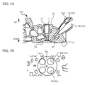
- FIG. 1A and FIG. 1B are views of a preformed article for a cylinder head (hereinafter, referred to as preformed article) 10A.
- FIG. 1A is a sectional view of the preformed article 10A
- FIG. 1B is a bottom plan view of the preformed article 10A.
- the vertical direction as illustrated in FIG. 1A , it is assumed that the vertical direction is perpendicular to the bottom surface and that the bottom surface is positioned at the lowermost position in the vertical direction.
- the preformed article 10A includes a portion 11 which is a first portion, and a portion 12 which is a second portion.
- the portion 11 is a portion where a through hole 15 to be described later is formed.
- the through hole 15 is specifically a through hole 15A or a through hole 15B to be described later.
- the portion 11 is specifically a portion including a prepared hole portion 11 a where the through hole 15 is formed.
- the prepared hole portion 11a is a first prepared hole portion, and is a prepared hole portion common to the through holes 15A and 15B which are formed beforehand in order to form the through hole 15.
- the prepared hole portion 11 a is a prepared hole portion formed from an upper wall portion 18 to a central portion 19a which is a portion, of a bottom wall portion 19, forming a combustion chamber of an internal combustion engine.
- the central portion 19a has a pent roof shape.
- the portion 12 is a portion where a through hole 16 to be described later is to be formed.
- the portion 12 is specifically a portion 12A
- the portion 12A is a portion including the prepared hole portion 12aA where the through hole 16 is to be formed.
- the prepared hole portion 12aA is a second prepared hole portion and is a prepared hole portion which is formed beforehand in order to form the through hole 16.
- the prepared hole portion 12aA is a prepared hole portion formed to an intake port 14 from an outer wall portion (the upper wall portion 18 in this case) positioned above the intake port 14 opening to the central portion 19a.
- the outer wall portion may be, for example, a side wall portion.
- the intake port 14 is specifically an intake port 14A which is an intake port common to cylinder heads 1A and 2A to be described later. Specifically, for example, a siamese port which branches into plural portions (two in this case) on the way to the central portion 19a and which opens thereto is applicable to the intake port 14.
- the portion 12A is a portion where the intake port 14 is partly formed.
- the portion 12A is a portion where a through hole 17 to be described later can be further formed. Therefore, the prepared hole portion 12aA is a prepared hole portion common to the through holes 16 and 17 where the through hole 16 or the through hole 17 is to be formed.
- the portions 11 and 12A are portions where a cooling water passage W which is a cooling medium passage is not formed.
- FIG. 2A and FIG. 2B are views of the cylinder head.
- FIG. 2A is a sectional view of the cylinder head 1A
- FIG. 2B is a bottom view of the cylinder head 1A.
- FIG. 2A and FIG. 2B illustrate the cylinder head 1A in the state where a fuel injection valve 31, a glow plug 32, intake valves 33, and exhaust valves 34 are provided.
- the intake valve 33 is specifically an intake valve 33A corresponding to the intake port 14A.
- the intake port 14 in the cylinder head 1A may be an intake port which is the intake port 14 which is predeterminedly processed in the preformed article 10A. This also applies to the cylinder head 2A to be described later.
- the cylinder head 1A is a first cylinder head in the present embodiment and is manufactured by using the preformed article 10A.
- the cylinder head 1A is a cylinder head of the compression ignition type internal combustion engine.
- the through hole 15 is a first through hole and is a through hole formed from the upper wall portion 18 to the central portion 19a.
- the through hole 15 is specifically the through hole 15A, and the through hole 15A is formed to be acceptable to the fuel injection valve 31. Therefore, in the cylinder head 1A, the fuel injection valve 31 is provided in the through hole 15A.
- the fuel injection valve 31 is a fuel injection valve for the compression ignition type internal combustion engine.
- the through hole 16 is a second through hole, and is a through hole formed from the above mentioned outer wall portion to the central portion 19a.
- the through hole 16 specifically is formed to be acceptable to the glow plug 32. Therefore, in the cylinder head 1A, the glow plug 32 is provided in the through hole 16.
- the through hole 16 is formed to at least partially overlap the intake port 14.
- An axis L12 of the through hole 16 is set as follows. That is, it is set to extend in the intake and exhaust direction (the direction perpendicular to the cylinder arrangement direction of the internal combustion engine) when viewed in the direction perpendicular to the bottom wall surface, as illustrated in FIG. 2B .
- the through hole 16 is set to open to the central portion of the intermediate portion between the intake ports 14 in the central portion 19a. Therefore, the through hole 16 opens to the central portion of the intermediate portion.
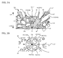
- FIG. 3A and FIG. 3B are views of the cylinder head 2A.
- FIG. 3A is a sectional view of the cylinder head 2A
- FIG. 3B is a bottom plan view of the cylinder head 2A.
- FIG. 3A and FIG. 3B illustrate the cylinder head 2A in the state where an ignition plug 41, a fuel injection valve 42, a fuel injection valve 43, and intake valves 44, and exhaust valves 45 are provided.
- the intake valve 44 is an intake valve 44A corresponding to the intake port 14A.
- the intake valve 44A may be the same as the intake valve 33A.
- the exhaust valve 45 may be the same as the exhaust valve 34.
- the cylinder head 2A is a second cylinder head in the present embodiment, and is manufactured by using the preformed article 10A.
- the cylinder head 2A is a cylinder head for a spark ignition type internal combustion engine, and is more specifically a cylinder head for a spark ignition type internal combustion engine with a turbocharger.
- the through hole 15 is a through hole formed from the upper wall portion 18 to the central portion 19a.
- the through hole 15 is specifically the through hole 15B, and the through hole 15B is formed to be acceptable to the ignition plug 41. Therefore, in the cylinder head 2A, the ignition plug 41 is provided in the through hole 15B.
- the through hole 15B is a through hole having an axis L11' which is the same as an axis L11 of the through hole 15A. Being “the same” includes a case where they differ from each other within a manufacturing error range. To be “the same” also includes a case where they differ from each other within a range where the present invention can have effects. This also applies to the following description.
- the through hole 17 is a through hole, and is a through hole formed the above mentioned outer wall portion to the intake port 14. Further, the through hole 17 is a through hole having an axis L12' which is the same as an axis L12 of the through hole 16. The through hole 17 specifically is formed to be acceptable to the fuel injection valve 42. Therefore, in the cylinder head 2A, the fuel injection valve 42 is provided in the through hole 17.
- the fuel injection valve 42 is a fuel injection valve for the spark ignition type internal combustion engine which injects fuel into the intake port 14.
- the fuel injection valve 43 is a fuel injection valve for the spark ignition type internal combustion engine which injects fuel directly into the combustion chamber of the internal combustion engine.
- the preformed article 10A further includes a portion where a through hole which is to be formed to the central portion 19a from the outer wall portion (the side wall portion in this case) positioned under the intake port 14.
- the portion is a portion where the cooling water passage W is not formed, and the through hole is to be formed to be acceptable to the fuel injection valve 43.
- the portion is a prepared hole portion where the through hole is to be formed, and may include a portion where an end portion is formed on the way to the central portion 19a.
- the prepared hole portion 11 a As for formation of the through holes 15A and 15B, in the prepared hole portion 11 a, a portion which needs processing to provide each corresponding component (the fuel injection valve 31 and the ignition plug 41) is smaller than each of the through holes 15A and 15B.
- the prepared hole portion 11 a can be formed such that the portion which does not need processing to provide each corresponding component does not interfere with each corresponding component.
- the prepared hole portion 12aA is a part of the through hole 16, so that the through hole 16 is formed in the prepared hole portion 12aA.
- the prepared hole portions 11a and 12aA are as follows. That is, the prepared hole portion 11 a may not always open to the central portion 19a. Thus, the prepared hole portion 11 a may be a prepared hole portion which has an end portion formed on the way to the central portion 19a. Likewise, the prepared hole portion 12aA may be a prepared hole portion which has an end portion formed on the way to the intake port 14. This also applies to a prepared hole portion 12aB and a prepared hole portion 13a to be described later.
- each of the through holes 15A, 15B, 16, and 17 and each of the prepared hole portions are as follows. That is, the corresponding prepared hole portion (the prepared hole portion 11 a or the prepared hole portion 12aA in this case) is at least partially each of the through holes 15A, 15B, 16, and 17 as it is, so that each of the through holes 15A, 15B, 16, and 17 may be formed in the corresponding prepared hole portion.
- the corresponding prepared hole portion (the prepared hole portion 11 a or the prepared hole portion 12aA in this case) may be a portion where at least any one of the corresponding through holes (at least any one of the through holes 15A and 15B, or at least any one of the through holes 16 and 17) is to be at least partially formed.
- the cylinder head 1A is manufactured through the process P11 which will be described later and which is a first step in the present embodiment. Further, the cylinder head 2A is manufactured through the process P12 which will be described later and which is a second step in the present embodiment.
- the process P11 is a process in which the through hole 15 is formed in the preformed article 10A to be acceptable to the fuel injection valve 31 (namely, the through hole 15A is formed) and the through hole 16 is formed to be acceptable to the glow plug 32.
- the process P12 is a process in which the through hole 15 is formed in the preformed article 10A to be acceptable to the ignition plug 41 (namely, the through hole 15B is formed) and the through hole 17 is formed to be acceptable to the fuel injection valve 42.
- the cylinder heads 1A and 2A are manufactured by selectively performing the process P11 or P12.
- the manufacturing method for the cylinder head (hereinafter referred to as manufacturing method M1) which includes these processes P11 and P12 and which selectively performs the process P11 or P12 is specifically achieved in the processing process which is the manufacturing process after the molding.
- the preformed article 10A is configured to include the portion 11, so that the fuel injection valve 31 or the ignition plug 41 can be selectively attached. Further, the preformed article 10A is configured to include the portion 12A, so that the glow plug 32 or the fuel injection valve 42 can be selectively attached.
- the preformed article 10A enables the selective attachment of the fuel injection valve 31 or the ignition plug 41, and further enables the attachment of the glow plug 32 in a manner suitable for the communization and the improvement in the commonality of the cylinder head between the compression ignition type internal combustion engine and the spark ignition type internal combustion engine. This can result in enhancement of the commonality of the cylinder head between these internal combustion engines.
- the portions 11 and 12A are configured to be a portion where the cooling water passage W is not formed.
- Such a configured preformed article 10A enables the selective and suitable attachment of the fuel injection valve 31 or the ignition plug 41 and of the glow plug 32 and the fuel injection valve 42.
- the portion 12A is configured to a portion where the through hole 17 can be further formed and the intake port 14 is partially formed.
- the through hole 16 is configured to be a through hole which is to be formed to at least partially overlap the intake port 14.
- the through hole 15 is configured to be formed to be acceptable to the fuel injection valve 31, and the second through hole 16 is configured to be formed to be acceptable to the glow plug 32.
- the through hole 15 is configured to be formed to be acceptable to the ignition plug 41, and the through hole 17 is configured to be formed to be acceptable to the fuel injection valve 42.
- Such a configured preformed article 10A is preferred as a preformed article common to the compression ignition type internal combustion engine and the spark ignition type internal combustion engine.
- the cylinder head 1A is manufactured by using the preformed article 10A. Therefore, the cylinder head 1A can reduce the manufacturing cost by the communization of the manufacturing process for the cylinder head between the compression ignition type internal combustion engine and the spark ignition type internal combustion engine. Further, in the cylinder head 1A, the through hole 15 is formed to be acceptable to the fuel injection valve 31, and the through hole 16 is formed to be acceptable to the glow plug 32. It is thus possible to obtain a cylinder head for the compression ignition type internal combustion engine on the basis of the cylinder head 1A.
- the cylinder head 2A is manufactured by using the preformed article 10A. Therefore, the cylinder head 2A can reduce the manufacturing cost by the communization of the manufacturing process for the cylinder head between the compression ignition type internal combustion engine and the spark ignition type internal combustion engine. Further, in the cylinder head 2A, the through hole 15 is formed to be acceptable to the ignition plug 41, and the through hole 17 is formed to be acceptable to the fuel injection valve 42. It is thus possible to obtain a cylinder head for the spark ignition type internal combustion engine on the basis of the cylinder head 2A.
- the cylinder heads 1A and 2A are manufactured by using the common preformed article 10A. Therefore, even in the casting process besides the processing process after the molding, the cylinder heads 1A and 2A can reduce the manufacturing cost by the communization of the manufacturing process for the cylinder head between the spark ignition type internal combustion engine and the compression ignition type internal combustion engine.
- the cylinder head 1A specifically is configured such that the axis L12 of the through hole 16 extends in the intake and exhaust direction when viewed in the direction perpendicular to the bottom wall surface. Therefore, in the cylinder head 1A, the through hole 16 can avoid limiting the process, so the opening portion of the intake port 14 can be set large in the central portion 19a. This can result in the improvement in fuel consumption based on the improvement in output and the reduction in pumping loss in the compression ignition type internal combustion engine. Additionally, the preformed article 10A in which the axis L12 of the through hole 16 is set in the same manner has the same effects.
- the distance between the fuel injection valve 31 and the glow plug 32 influences as follows. That is, too long distance degrades the ignitability of the glow plug 32. Too short distance causes the glow plug 32 to block the diffusion of the spray, which tends to generate smoke in the high load.
- the cylinder head 1A is configured such that the intake port 14 is set to open to two positions of the central portion 19a, and such that the through hole 16 is set to open to the central portion between the intermediate portion of each intake port 14 in the central portion 19a.
- a configured cylinder head 1A can set the suitable distance between the fuel injection valve 31 and the glow plug 32 in the combustion chamber of the compression ignition type internal combustion engine.
- the preformed article 10A in which the intake port 14 is set to open to two positions of the central portion 19a and in which the through hole 16 is set in the same manner has the same effects. This applies to a cylinder head 1B and a preformed article 10B corresponding to the cylinder head 1B to be described later in the second embodiment.
- the cylinder head 1A specifically is configured such that the central portion 19a has a pent roof shape. Therefore, the cylinder head 1A can suppress generation of smoke in the high load in the compression ignition type internal combustion engine, as will be described later.
- FIG. 4A and FIG. 4B are views of an example of a compression ignition type internal combustion engine.
- FIG. 4A illustrates an internal combustion engine 50 as an example of the compression ignition type internal combustion engine using the cylinder head 1A.
- FIG. 4B illustrates an internal combustion engine 50' as an example of a typical compression ignition type internal combustion engine.
- the distance between the fuel injection valve 31 and the glow plug 32 is set to be suitable.
- the internal combustion engine 50 enables the fuel spray to contact the glow plug 32 by an angle close to the vertical, as compared with the internal combustion engine 50'.
- the internal combustion engine 50 can ensure the ignitability while reducing the exposure degree of the glow plug 32 from the combustion chamber, as compared to the internal combustion engine 50'.
- the cylinder head 1A can ensure the ignitability while reducing the exposure degree of the glow plug 32 from the combustion chamber.
- the cylinder head 1A can suppress generation of smoke in the high load in the internal combustion engine 50.
- the preformed article 10A in which the central portion 19a has a pent roof shape has the same effects.
- the manufacturing method M1 includes the processes P11 and P12 and selectively performs the process P11 or P12.
- the manufacturing method M1 can reduce the manufacturing cost by the communization of the manufacturing process for the cylinder head between the compression ignition type internal combustion engine and the spark ignition type internal combustion engine.
- the manufacturing method M1 can reduce the manufacturing cost, specifically, in the processing process after the molding.
- a cutting tool is replaced or an angle is slightly corrected between the through holes 15A and 15B and between the through holes 16 and 17, whereby the machining equipment can be used in common.
- the communization of the machining equipment enables the reduction in the manufacturing cost.
- FIG. 5A and FIG. 5B are views of the preformed article 10B.
- FIG. 5A is a sectional view of the preformed article
- FIG. 5A is a bottom view of the preformed article 10B.
- the preformed article 10B is a first preformed article in the present embodiment and is the same as the preformed article 10A, except that the intake port 14 is specifically an intake port 14B different from the intake port 14A and that the portion 12 is specifically a portion 12B different from the portion 12A.
- the intake port 14B is an independent intake port in which the plural intake ports (two in this case) are provided independently of each other in the central portion 19a.
- the specific shape of each intake port 14B may be different from each other.
- the two intake ports 14B are applicable to, for example, a helical port and a tangential port capable of forming a swirl flow.
- the portion 12B is a second portion instead of the portion 12A and is the same as the portion 12A, except that the prepared hole portion 12aB is provided instead of the prepared hole portion 12aA and that the following will be described below.
- the prepared hole portion 12aB is a second prepared hole portion instead of the prepared hole portion 12aA and is the same as the prepared hole portion 12aA, except that the prepared hole portion is formed to the central portion 19a instead of the intake port 14.
- the portion 12B is where the intake port 14 is not formed. Therefore, the portion 12B is not formed such that the through hole 16 overlaps the intake port 14. Additionally, the portion 12B can be a portion where the intake port 14 is further formed in part, and the through hole 16 can be a through hole which is to be formed to at least partially overlap the intake port 14.
- the prepared hole portion 11a is specifically a prepared hole portion where the through hole 15A is to be formed.
- the prepared hole portion 11 a may not be always a through hole common to the through holes 15A and 15B.
- the specific shape of the prepared hole portion 11 a in the preformed article 10B may differ from the shape of the prepared hole portion 11 a in the preformed article 10A.
- the through hole 16 may not always open to the outer wall portion positioned above the intake port 14. That is, for example, the through hole 16 may open to the side wall portion, and each intake port 14B may open to the side wall portion so as to sandwich the through hole 16.
- FIG. 6A and FIG. 6B are views of a preformed article 10C.
- FIG. 6A is a sectional view of the preformed article 10C
- FIG. 6B is a bottom view of the preformed article 10C.
- the preformed article 10C is a second preformed article in the present embodiment and is the same as the preformed article 10B, except that a portion 11' is provided instead of the portion 11, that a central portion 19a' is provided instead of the central portion 19a, that the intake port 14 is specifically an intake port 14C different from the intake port 14B, and that a portion 13 is provided instead of the portion 12.
- the portion 11' is the same as the portion 11 in the preformed article 10B.
- the portion 11' is specifically a portion including a prepared hole portion 11 a' which is the same as the prepared hole portion 11 a in the preformed article 10B.
- the prepared hole portion 11a' is a through hole where the through hole 15B is to be formed.
- the central portion 19a' is the same central portion as the central portion 19a in the preformed article 10B.
- the specific shape of the prepared hole portion 11a' may differ from the shape of the prepared hole portion 11 a in the preformed article 10B.
- the intake port 14C opens to the central portion 19a'.
- the intake port 14C is a siamese port which branches into plural portions (two in this case) on the way to a central portion 19' and which opens thereto.
- the specific shape is not limited due to the intake port such as the intake port 14A common to the cylinder heads 1A and 2A. Therefore, an intake port having an inner diameter different from an opening portion, of the intake port 14A, opening to the central portion 19 is applied to an opening portion, of the intake port 14C, opening to the central portion 19'.
- the intake port 14C may be the same as the intake port 14A.
- the portion 13 is a portion where the through hole 17 described above is to be formed.
- the portion 13 is a portion where the intake port 14 is partially formed. Specifically, an end portion of the portion 13 is where the intake port 14 is partly formed.
- the portion 13 is specifically a portion including the prepared hole portion 13a.
- the prepared hole portion 13a is a third through hole, and the prepared hole portion 13a is where the through hole 17 is to be formed.
- the prepared hole portion 13a is a prepared hole portion formed from the above mentioned outer wall portion to the intake port 14.
- the prepared hole portion 13a may be the same as the prepared hole portion 12aA in shape.
- the portion 13 is a portion where the cooling water passage W is not formed.
- the preformed article 10B is manufactured by partially changing the casting process for the preformed article 10C which is another preformed article.
- the part change specifically includes at least one (both in this case) of a first change and a second change to be described below.
- the first change is a change to differ from the portion 13 (specifically, the prepared hole portion 13 a) provided in the preformed article 10C.
- the first change is specifically a change from the portion 13 to the portion 12B (specifically, a change from the prepared hole portion 13a to the prepared hole portion 12aB).
- the second change is a change to differ from the intake port 14C provided in the preformed article 10C.
- the second change is specifically a change from the intake port 14C to the intake port 14B.
- the portions 11, 11', 12B, and 13 (specifically, the prepared hole portions 11a, 11a', 12aB, and 13a) and the intake ports 14B and 14C are formed by a core in the casting process.
- the preformed article 10B is manufactured by replacing the core between the preformed articles 10B and 10C in the casting process. Therefore; the partial change to be performed between the preformed articles 10B and 10C in the casting process is more specifically a partial change by replacing the core.
- the preformed article 10C is manufactured by partially changing the casting process between the preformed articles 10B and 10A. Accordingly, from the point of view of the preformed article 10C, the partial change includes at least one (both in this case) of the first change and the second change described below.
- the first change in this case is a change to differ from the portion 12B (specifically, the prepared hole portion 12aB) provided in the preformed article 10B.
- the first change in this case is specifically a change from the portion 12B into the portion 13 (specifically, a changes from the prepared hole portion 12aB to the prepared hole portion 13a).
- the second change in this case is a change to differ from the intake port 14B provided in the preformed article 10B.
- the second change in this case is specifically a change from the intake ports 14B into the intake ports 14C.
- the partial change which is performed between the preformed articles 10B and 10C in the casting process has only to be a change within a range where the present invention can have effects.
- the partial change may include, for example, a change in specific shape between the portions 11 and 11' (specifically, between the prepared hole portions 11a and 11a'), a change in the cooling water passage W, a change in the prepared hole portion where the through hole is to be formed to be acceptable to the fuel injection valve 43, and other changes.
- FIG. 7A and FIG. 7B are views of the cylinder head 1B.
- FIG. 7A is a sectional view of the cylinder head 1B
- FIG. 7B is a bottom view of the cylinder head 1B.
- FIG. 7A and FIG. 7B illustrate the cylinder head 1B in the state where the fuel injection valve 31, the glow plug 32, the intake valves 33, and the exhaust valve 34 are provided.
- the intake valve 33 is specifically an intake valve 33B corresponding to the intake port 14B.
- the intake port 14 in the cylinder head 1B may be an intake port formed by processing the intake port 14 in a predetermined manner.
- the cylinder head 1B is a first cylinder head in the present embodiment and is manufactured by using the preformed article 10B.
- the cylinder head 1B is a cylinder head for the compression ignition type internal combustion engine.
- the cylinder head 1B is the same as the cylinder head 1A, except that the intake port 14B is provided instead of the intake port 14A, and that the through hole 16 is not formed so as to overlap the intake port 14.
- the specific shape of the through hole 16 in the cylinder head 1B may differ from the shape of the through hole 16 in the cylinder head 1A due to the through hole 16 formed so as not to overlap the intake port 14 or due to the shape of the prepared hole portion 12aB.
- FIG. 8A and FIG. 8B are views of a cylinder head 2B.
- FIG. 8A is a sectional view of the cylinder head 2B
- FIG. 8B is a bottom view of the cylinder head 2B.
- FIG. 8A and FIG. 8B illustrate the cylinder head 2B in the state where the ignition plug 41, the fuel injection valve 42, the fuel injection valve 43, intake valves 44, and exhaust valves 45.
- the intake valve 44 is specifically an intake valve 44B corresponding to the intake ports 14C.
- the intake port 14 in the cylinder head 2B may be an intake port formed by processing the preformed article 10C in the intake port 14 in a predetermined manner.
- the cylinder head 2B is a second cylinder head in the present embodiment and is manufactured by using the preformed article 10C.
- the cylinder head 2B is a cylinder head for the spark ignition type internal combustion engine and is specifically a cylinder head for the spark ignition type internal combustion engine hiving a turbocharger.
- the cylinder head 2B is the same as the cylinder head 2A, except that the intake port 14C is provided instead of the intake port 14A.
- the specific shape of the through hole 17 in the cylinder head 2B may differ from the shape of the through hole 17 in the cylinder head 2A due to the shape of the prepared hole portion 13a.
- the through hole 15B has the same arrangements.
- axes L21 and L21' of respective insertion holes for the intake valves 33B and 44B arranged in the same manner in the cylinder heads 1B and 2B are the same as each other.
- Axes L22 and L22' of respective insertion holes for the exhaust valves 34 and 45 arranged in the same manner in the cylinder heads 1B and 2B are also the same as each other.
- An inner diameter of an opening portion opening to the central portion 19a in the intake port 14B is smaller than that of an opening portion opening to the central portion 19a' in the intake port 14C.
- a valve seat diameter of the intake valve 33B is smaller than that of the intake valve 44B.
- the preformed articles 10B and 10C are configured in further consideration of the insertion holes for the intake valves 33B and 44B, the insertion holes for the exhaust valves 34 and 45, and the opening portions of the intake ports 14B and 14C.
- the preformed article 10B further includes a portion where the insertion hole for the intake valve 33B is to be formed, the insertion hole is provided in the cylinder head 2B manufactured by using the preformed article 10C, and there is the provision of the axis L21 which is configured to be the same as the axis L21' of the insertion hole for the intake valve 44B arranged in the same manner as the intake valve 33B.
- the preformed article 10C further includes a portion where the insertion hole for the intake valve 44B is to be formed, the insertion hole is provided in the cylinder head 1B manufactured by using the preformed article 10B, and there is the provision of the axis L21' which is configured to be the same as the axis L21 of the insertion hole for the intake valve 33B arranged in the same manner as the intake valve 44B.
- the preformed article 10B further includes a portion where the insertion hole for the exhaust valve 34 is to be formed, the insertion hole is provided in the cylinder head 2B manufactured by using the preformed article 10C, and there is the provision of the axis L22 which is configured to be the same as the axis L22' of the insertion hole for the exhaust valve 45 arranged in the same manner as the exhaust valve 34.
- the preformed article 10C further includes a portion where the insertion hole for the exhaust valve 45 is to be formed, the insertion hole is provided in the cylinder head 1B manufactured by using the preformed article 10B, and there is the provision of the axis L22' which is configured to be the same as the axis L22 of the insertion hole for the exhaust valve 34 arranged in the same manner as the exhaust valve 45.
- Respective portions where the insertion holes for the intake valves 33B and 44B and the insertion holes for the exhaust valves 34 and 45 are to be formed can be portions including respective prepared hole portions where the insertion holes for the corresponding intake valves 33B and 44B and the exhaust valves 34 and 45 are to be formed.
- the portion can be a portion where the cooling water passage W is not formed.
- Each prepared hole portion can be specifically a prepared hole portion formed from the upper wall portion 18 to the intake port 14 or the exhaust port.
- Each prepared hole portion can be a portion where an insertion hole each for corresponding intake valves 33B and 44B and exhaust valves 34 and 45 is to be at least partially formed.
- the preformed article 10B is configured to be provided with the opening portion which opens to the central portion 19a in the intake port 14B and which has the inner diameter smaller than that of the opening portion opening to the central portion 19a' in the intake port 14C provided in the preformed article 10C.
- the preformed article 10C is configured to be provided with the opening portion which opens to the central portion 19a' in the intake port 14C and which has the inner diameter larger than that of the opening portion opening to the central portion 19a in the intake port 14B provided in the preformed article 10B.
- the cylinder head 1B is manufactured through the process P21 which will be described later and which is a first step in the present embodiment. Further, the cylinder head 2B is manufactured through the process P22 which is a second step in the present embodiment described later.
- the process P21 is a process in which the through hole 15 is formed in the preformed article 10B to be acceptable to the fuel injection valve 31 (namely, the through hole 15A is formed) and the through hole 16 is formed to be acceptable to the glow plug 32.
- the process P22 is a process in which the through hole 15 is formed in the preformed article 10C to be acceptable to the ignition plug 41 (namely, the through hole 15B is formed) and the through hole 17 is formed to be acceptable to the fuel injection valve 42.
- the preformed articles 10B and 10C are preformed articles manufactured by partially changing them.
- the cylinder heads 1 B and 2B are manufactured by selectively performing the process P21 or P22 to the preformed article 10B or 10C.
- the manufacturing method for the cylinder head (hereinafter referred to as manufacturing method M2) which includes these processes P21 and P22 and which selectively performs the process P21 or P22 to the preformed article 10B or 10C is achieved, specifically, in the processing process common to the preformed articles 10B and 10C of the manufacturing process after the molding.
- the preformed article 10B is a configured to be manufactured by partially changing the casting process between the preformed articles 10B and 10C.
- Such a configured preformed article 10B can be obtained as a preformed article, for the compression ignition type internal combustion engine, suitable for the communization of the manufacturing process for the molded cylinder head.
- the preformed article 10C is a configured to be manufactured by partially changing the casting process between the preformed articles 10B and 10C.
- Such a configured preformed article 10B can be obtained as a preformed article, for the spark ignition type internal combustion engine, suitable for the communization of the manufacturing process for the molded cylinder head.
- the cylinder head 1B is manufactured by using the preformed article 10B. Therefore, the cylinder head 1B can reduce the manufacturing cost by the communization of the manufacturing process for the cylinder head between the compression ignition type internal combustion engine and the spark ignition type internal combustion engine. Further, in the cylinder head 1B, the through hole 15 is formed to be acceptable to the fuel injection valve 31, and the through hole 16 is formed to be acceptable to the glow plug 32. It is thus possible to obtain specifically a cylinder head for the compression ignition type internal combustion engine on the basis of the cylinder head 1A.
- the cylinder head 2B is manufactured by using the preformed article 10C. Therefore, the cylinder head 2B can reduce the manufacturing cost by the communization of the manufacturing process for the cylinder head between the compression ignition type internal combustion engine and the spark ignition type internal combustion engine. Further, in the cylinder head 2B, the through hole 15 is formed to be acceptable to the ignition plug 41, and the through hole 17 is formed to be acceptable to the fuel injection valve 42. It is thus possible to obtain specifically a cylinder head for the spark ignition type internal combustion engine on the basis of the cylinder head 2B.
- the cylinder heads 1B and 2B are specifically cylinder heads which can reduce the manufacturing cost by the communization of, specifically, the processing process which is the manufacturing process for the molded cylinder head.
- the preformed article 10B in which the through hole 15 is to be formed to be acceptable to the fuel injection valve 31 and in which the through hole 16 is to be formed to be acceptable to the glow plug 32 is a preformed article which enables the above mentioned effects.
- the preformed article 10C in which the through hole 15 is to be formed to be acceptable to the ignition plug 41 and in which the through hole 17 is to be formed to be acceptable to the fuel injection valve 42 is a preformed article which enables the above mentioned effects.
- the cylinder head 1B is configured to have the axis L21, of the insertion hole for the intake valve 33B, the same as the axis L21' of the insertion hole for the intake valve 44B provided in the cylinder head 2B in the same manner as the intake valve 33B.
- the cylinder head 2B is configured to have the axis L21', of the insertion hole for the intake valve 44B, the same as the axis L21 of the insertion hole for the intake valve 33B provided in the cylinder head 1B in the same manner as the intake valve 44B.
- the cylinder heads 1B and 2B enables further enhancement of the commonality of the cylinder head between the compression ignition type internal combustion engine and the spark ignition type internal combustion engine. As a result, it is possible to further reduce the manufacturing cost by the communization of the processing process after the molding.
- the cylinder heads 1B and 2B enable the common use of the machining equipment for, specifically, for example, the processing for a seat portion on which the intake valve 33B or 44B closes and abuts, the processing for a stem guide portion, and the hole processing for a lash adjuster. Further, the cylinder heads 1B and 2B facilitate the assembling of the intake valves 33B and 44B, for example, in the assembling process, thereby also reducing the manufacturing cost. In addition, the preformed articles 10B and 10C further considering the insertion holes for the intake valves 33B and 44B also have the same effects.
- the cylinder head 1B is configured to have the axis L22, of the insertion hole for the exhaust valve 34, the same as the axis L22' of the insertion hole for the exhaust valve 45 provided in the cylinder head 2B in the same manner as the exhaust valve 34.
- the cylinder head 2B is configured to have the axis L22', of the insertion hole for the exhaust valve 45, the same as the axis L22 of the insertion hole for the exhaust valve 34 provided in the cylinder head 1B in the same manner as the exhaust valve 45.
- the cylinder heads 1B and 2B enables further enhancement of the commonality of the cylinder head between the compression ignition type internal combustion engine and the spark ignition type internal combustion engine. As a result, it is possible to further reduce the manufacturing cost by the communization of the processing process after the molding.
- the preformed articles 10B and 10C further considering the insertion holes for the exhaust valves 34 and 45 also have the same effects.
- the cylinder head 1B is configured to be provided with the opening portion which opens to the central portion 19a in the intake port 14B and which has the inner diameter smaller than that of the opening portion opening to the central portion 19a' in the intake port 14C provided in the cylinder head 2B. Therefore, the cylinder head 1B can further ensure the installation space for the glow plug 32 in a preferable manner.
- the preformed article 10b further considering the openings of the intake port 14B and 14C also has the same effects.
- the cylinder head 2B is configured to be provided with the opening portion which opens to the central portion 19a' in the intake port 14C and which has the inner diameter larger than that of the opening portion opening to the central portion 19a in the intake port 14B provided in the cylinder head 1B.
- the cylinder head 2B can also reduce the fuel consumption based on the improvement in output and the reduction in pumping loss in the internal combustion engine, as compared with the cylinder head 2A.
- the preformed article 10C further considering the openings of the intake port 14B and 14C also has the same effects.
- the cylinder head 1B is configured specifically such that the central portion 19a has a pent roof shape. Therefore, like the cylinder head 1A, the cylinder head 1B can suppress generation of smoke in the high load in the compression ignition type internal combustion engine. Further, such a configured cylinder head 1B can further enhance the commonality of the cylinder head between the compression ignition type internal combustion engine and the spark ignition type internal combustion engine.
- the preformed article 10B in which the central portion 19a has a pent roof shape also has the same effects.
- the manufacturing method M2 includes the processes P21 and P22 and selectively performs the process P21 or P22 to the preformed article 10B or 10C.
- the manufacturing method M2 can reduce the manufacturing cost by the communization of the manufacturing process for the cylinder head between the compression ignition type internal combustion engine and the spark ignition type internal combustion engine.
- the manufacturing method M2 can reduce the manufacturing cost, specifically, in the processing process after the molding.
- the intake port may open at one point in the central portion.
- the first portion and the second portion may be a material portions.
- the first portion and the second portion may be portions to which lightening its weight is at least partially applied.
- the central portion can also have, for example, a flat shape instead of a pent roof shape.
- the partial change which is performed between the preformed articles in the casting process has only to be a change in other portions than each prepared hole portion included in the second and third portions and than the intake port, as long as the present invention can have effects.
- each prepared hole portion included in the second and third portions may be common, and the intake port may be common, whereas the other portions are different.
Landscapes
- Engineering & Computer Science (AREA)
- Chemical & Material Sciences (AREA)
- Combustion & Propulsion (AREA)
- Mechanical Engineering (AREA)
- General Engineering & Computer Science (AREA)
- Cylinder Crankcases Of Internal Combustion Engines (AREA)
- Spark Plugs (AREA)
Abstract
Description
- The present invention is related to a preformed article for a cylinder head, cylinder head, and method for manufacturing cylinder head.
- In some cases, a part is communized between a compression ignition type internal combustion engine (for example, diesel engine) and a spark ignition type internal combustion engine (for example, a gasoline engine), and the commonality is improved.
Patent Document 1 discloses a direct injection diesel engine having a cylinder head common to a cylinder head of a gasoline engine. - [Patent Docuemnt 1] Japanese Unexamined Patent Application Publication No.
11-257089 - In many cases, the compression ignition type internal combustion engine is attached with a glow plug in order to ensure ignitability of the fuel. Therefore, in view of the communization of the cylinder head between the compression ignition type internal combustion engine and the spark ignition type internal combustion engine and in view of the improvement in commonality, it is desired that a technique considers attaching the glow plug.
- In view of the above circumstances, it is an object of the present invention to apply a preformed article for a cylinder head enabling enhancement of the communization of a cylinder head between internal combustion engines by enabling attachment of a glow plug in a manner suitable for the communization and the improvement in the commonality of the cylinder head between a compression ignition type internal combustion engine and a spark ignition type internal combustion engine.
- It is a further object of the present invention to provide a preformed article for a cylinder head common to these internal combustion engines by enabling attachment of a glow plug in a manner suitable for the communization and the improvement in the commonality of the cylinder head between these internal combustion engines, or to provide a preformed article for a cylinder head suitable for the communization of manufacturing process for the molded cylinder head in each internal combustion engine.
- It is a further object of the present invention to provide a cylinder head enabling a reduction in the manufacturing cost by the communization of the manufacturing process for the cylinder head between these internal combustion engines by using these preformed articles for these cylinder head.
- It is a further object of the present invention to provide a method for manufacturing a cylinder head enabling a reduction in the manufacturing cost by the communization of the manufacturing process for the cylinder head between these internal combustion engines.
- The present invention is a preformed article for a cylinder head, the preformed article including: a first portion where a first through hole is to be formed from an upper wall portion to a central portion which is a portion, of a bottom wall portion, forming a combustion chamber of an internal combustion engine; and a second portion where a second through hole is to be formed to the central portion from an outer wall portion positioned above an intake port which opens to the central portion.
- In the above mentioned preformed article, it may be configured that the first and second portions are portions where a cooling medium passage is not formed.
- In the above mentioned preformed article, it may be configured that the second portion is a portion where a third through hole is capable of being further formed and where the intake port is partially formed, the second through hole is a through hole which is to be formed to at least partially overlap the intake port, and the third through hole is a through hole which is formed from the outer wall portion to the intake port and which has a same axis as an axis of the second through hole.
- In the above mentioned preformed article, it may be configured that when the first and second through holes are formed, the first through hole is to be formed to be acceptable to a fuel injection valve, and the second through hole is formed to be acceptable to a glow plug, when the first and third through holes are formed, the first through hole is to be formed to be acceptable to an ignition plug, and the third through hole is to be formed to be acceptable to another fuel injection valve different from the fuel injection valve.
- According to another aspect of the present invention, there is provided a cylinder head manufactured by using the preformed article for the cylinder head, wherein the first through hole is formed to be acceptable to a fuel injection valve, the second through hole is formed to be acceptable to a glow plug.
- According to another aspect of the present invention, there is provided a cylinder head manufactured by using the preformed article for the cylinder head, wherein the first through hole is formed to be acceptable to an ignition plug, the third through hole is formed to be acceptable to a fuel injection valve.
- According to another further aspect, there is provided a method for manufacturing a cylinder head by using a preformed article for the cylinder head, the preformed article for the cylinder head including: a first portion where a first through hole is to be formed from an upper wall portion to a central portion which is a portion, of a bottom wall portion, forming a combustion chamber of an internal combustion engine; and a second portion where a second through hole is to be formed to the central portion from an outer wall portion positioned above an intake port which opens to the central portion, the method comprising: a first step of forming, in the preformed article for the cylinder head, a first through hole to be acceptable to a fuel injection valve, and a second through hole to be acceptable to a glow plug; and a second step of forming, in the preformed article for the cylinder head, the first through hole to be acceptable to an ignition plug, and the third through hole to be acceptable to another fuel injection valve different from the fuel injection valve, wherein the first step and the second step are selectively performed.
- In the above mentioned method for manufacturing the cylinder head, it may be configured that the outer wall portion is positioned above an intake port which opens to the central portion, the second portion is a portion where a third through hole is capable of being further formed and where the intake port is partially formed, the second through hole is a through hole which is to be formed to at least partially overlap the intake port, and the third through hole is a through hole which is formed from the outer wall portion to the intake port and which has a same axis as an axis of the second through hole.
- In the above mentioned method for manufacturing the cylinder head, it may be configured that the preformed article for the cylinder head includes a first preformed article for the cylinder head and a second preformed article for the cylinder head, the first preformed article for the cylinder head includes the first portion and the second portion, the second preformed article for the cylinder head includes: a same first portion as the first portion; and a third portion where a third through hole is to be formed, the third portion is a portion where an intake port is partially formed, and the third through hole is a through hole which is formed from the outer wall portion to the intake port and which has a same axis as an axis of the second through hole.
- According to the present invention, it is possible to enhance communization of a cylinder head between internal combustion engines by enabling attachment of a glow plug in a manner suitable for the communization and the improvement in the commonality of the cylinder head between a compression ignition type internal combustion engine and a spark ignition type internal combustion engine.
- According to the present invention, it is further possible to obtain a preformed article for a cylinder head common to these internal combustion engines by enabling attachment of a glow plug in a manner suitable for the communization and the improvement in the commonality of the cylinder head between these internal combustion engines, or to obtain a preformed article for a cylinder head suitable for the communization of manufacturing process for the molded cylinder head in each internal combustion engine.
- According to the present invention, it is further possible to obtain a cylinder head enabling a reduction in the manufacturing cost by the communization of the manufacturing process for the cylinder head between these internal combustion engines by using these preformed articles for these cylinder head.
- According to the present invention, it is further possible to obtain a method for manufacturing a cylinder head enabling a reduction in the manufacturing cost by the communization of the manufacturing process for the cylinder head between these internal combustion engines.
-
-
FIG. 1A is a sectional view of a preformed article for a cylinder head according to a first embodiment, andFIG. 1B is a bottom plan view of the preformed article for the cylinder head; -
FIG. 2A is a sectional view of a first cylinder head in the first embodiment, andFIG. 2B is a bottom plan view of the cylinder head; -
FIG. 3A is a sectional view of a second cylinder head in the first embodiment, andFIG. 3B is a bottom plan view of the cylinder head; -
FIG. 4A illustrates an example of a compression ignition type internal combustion engine using the first cylinder head in the first embodiment, andFIG. 4B illustrates an example of a general compression ignition type internal combustion engine; -
FIG. 5A is a sectional view of a preformed article for a first cylinder head in a second embodiment, andFIG. 5B is a bottom plan view of the preformed article for the cylinder head; -
FIG. 6A is a sectional view of the preformed article for a second cylinder head in the second embodiment, andFIG. 6B is a bottom plan view of the preformed article for the cylinder head; -
FIG. 7A is a sectional view of the first cylinder head in the second embodiment, andFIG. 7B is a bottom plan view of the cylinder head; and -
FIG. 8A is a sectional view of the second cylinder head in the second embodiment, andFIG. 8B is a bottom plan view of the cylinder head. - Embodiments according to the present invention will be described with reference to the drawings.
-
FIG. 1A and FIG. 1B are views of a preformed article for a cylinder head (hereinafter, referred to as preformed article) 10A.FIG. 1A is a sectional view of thepreformed article 10A, andFIG. 1B is a bottom plan view of thepreformed article 10A. Additionally, as for the vertical direction, as illustrated inFIG. 1A , it is assumed that the vertical direction is perpendicular to the bottom surface and that the bottom surface is positioned at the lowermost position in the vertical direction. - The preformed
article 10A includes aportion 11 which is a first portion, and aportion 12 which is a second portion. Theportion 11 is a portion where a throughhole 15 to be described later is formed. The throughhole 15 is specifically a throughhole 15A or a throughhole 15B to be described later. Theportion 11 is specifically a portion including aprepared hole portion 11 a where the throughhole 15 is formed. Theprepared hole portion 11a is a first prepared hole portion, and is a prepared hole portion common to the throughholes hole 15. Specifically, theprepared hole portion 11 a is a prepared hole portion formed from anupper wall portion 18 to acentral portion 19a which is a portion, of abottom wall portion 19, forming a combustion chamber of an internal combustion engine. Thecentral portion 19a has a pent roof shape. - The
portion 12 is a portion where a throughhole 16 to be described later is to be formed. Theportion 12 is specifically aportion 12A, and theportion 12A is a portion including the prepared hole portion 12aA where the throughhole 16 is to be formed. Specifically, the prepared hole portion 12aA is a second prepared hole portion and is a prepared hole portion which is formed beforehand in order to form the throughhole 16. Specifically, the prepared hole portion 12aA is a prepared hole portion formed to anintake port 14 from an outer wall portion (theupper wall portion 18 in this case) positioned above theintake port 14 opening to thecentral portion 19a. The outer wall portion may be, for example, a side wall portion. - The
intake port 14 is specifically anintake port 14A which is an intake port common tocylinder heads central portion 19a and which opens thereto is applicable to theintake port 14. - The
portion 12A is a portion where theintake port 14 is partly formed. Theportion 12A is a portion where a throughhole 17 to be described later can be further formed. Therefore, the prepared hole portion 12aA is a prepared hole portion common to the throughholes hole 16 or the throughhole 17 is to be formed. Theportions -
FIG. 2A and FIG. 2B are views of the cylinder head.FIG. 2A is a sectional view of thecylinder head 1A, andFIG. 2B is a bottom view of thecylinder head 1A.FIG. 2A and FIG. 2B illustrate thecylinder head 1A in the state where afuel injection valve 31, aglow plug 32,intake valves 33, andexhaust valves 34 are provided. Theintake valve 33 is specifically anintake valve 33A corresponding to theintake port 14A. Additionally, theintake port 14 in thecylinder head 1A may be an intake port which is theintake port 14 which is predeterminedly processed in the preformedarticle 10A. This also applies to thecylinder head 2A to be described later. - The
cylinder head 1A is a first cylinder head in the present embodiment and is manufactured by using the preformedarticle 10A. Thecylinder head 1A is a cylinder head of the compression ignition type internal combustion engine. - The through
hole 15 is a first through hole and is a through hole formed from theupper wall portion 18 to thecentral portion 19a. The throughhole 15 is specifically the throughhole 15A, and the throughhole 15A is formed to be acceptable to thefuel injection valve 31. Therefore, in thecylinder head 1A, thefuel injection valve 31 is provided in the throughhole 15A. Thefuel injection valve 31 is a fuel injection valve for the compression ignition type internal combustion engine. The throughhole 16 is a second through hole, and is a through hole formed from the above mentioned outer wall portion to thecentral portion 19a. The throughhole 16 specifically is formed to be acceptable to theglow plug 32. Therefore, in thecylinder head 1A, theglow plug 32 is provided in the throughhole 16. The throughhole 16 is formed to at least partially overlap theintake port 14. - An axis L12 of the through
hole 16 is set as follows. That is, it is set to extend in the intake and exhaust direction (the direction perpendicular to the cylinder arrangement direction of the internal combustion engine) when viewed in the direction perpendicular to the bottom wall surface, as illustrated inFIG. 2B . The throughhole 16 is set to open to the central portion of the intermediate portion between theintake ports 14 in thecentral portion 19a. Therefore, the throughhole 16 opens to the central portion of the intermediate portion. -
FIG. 3A and FIG. 3B are views of thecylinder head 2A.FIG. 3A is a sectional view of thecylinder head 2A, andFIG. 3B is a bottom plan view of thecylinder head 2A.FIG. 3A and FIG. 3B illustrate thecylinder head 2A in the state where anignition plug 41, afuel injection valve 42, afuel injection valve 43, andintake valves 44, andexhaust valves 45 are provided. Theintake valve 44 is anintake valve 44A corresponding to theintake port 14A. Theintake valve 44A may be the same as theintake valve 33A. Likewise, theexhaust valve 45 may be the same as theexhaust valve 34. - The
cylinder head 2A is a second cylinder head in the present embodiment, and is manufactured by using the preformedarticle 10A. Thecylinder head 2A is a cylinder head for a spark ignition type internal combustion engine, and is more specifically a cylinder head for a spark ignition type internal combustion engine with a turbocharger. - Like the
cylinder head 1A, the throughhole 15 is a through hole formed from theupper wall portion 18 to thecentral portion 19a. On the other hand, the throughhole 15 is specifically the throughhole 15B, and the throughhole 15B is formed to be acceptable to theignition plug 41. Therefore, in thecylinder head 2A, theignition plug 41 is provided in the throughhole 15B. The throughhole 15B is a through hole having an axis L11' which is the same as an axis L11 of the throughhole 15A. Being "the same" includes a case where they differ from each other within a manufacturing error range. To be "the same" also includes a case where they differ from each other within a range where the present invention can have effects. This also applies to the following description. - The through
hole 17 is a through hole, and is a through hole formed the above mentioned outer wall portion to theintake port 14. Further, the throughhole 17 is a through hole having an axis L12' which is the same as an axis L12 of the throughhole 16. The throughhole 17 specifically is formed to be acceptable to thefuel injection valve 42. Therefore, in thecylinder head 2A, thefuel injection valve 42 is provided in the throughhole 17. Thefuel injection valve 42 is a fuel injection valve for the spark ignition type internal combustion engine which injects fuel into theintake port 14. Additionally, thefuel injection valve 43 is a fuel injection valve for the spark ignition type internal combustion engine which injects fuel directly into the combustion chamber of the internal combustion engine. - As for the
fuel injection valve 43, the preformedarticle 10A further includes a portion where a through hole which is to be formed to thecentral portion 19a from the outer wall portion (the side wall portion in this case) positioned under theintake port 14. The portion is a portion where the cooling water passage W is not formed, and the through hole is to be formed to be acceptable to thefuel injection valve 43. The portion is a prepared hole portion where the through hole is to be formed, and may include a portion where an end portion is formed on the way to thecentral portion 19a. - As for formation of the through
holes prepared hole portion 11 a, a portion which needs processing to provide each corresponding component (thefuel injection valve 31 and the ignition plug 41) is smaller than each of the throughholes prepared hole portion 11 a can be formed such that the portion which does not need processing to provide each corresponding component does not interfere with each corresponding component. On the other hand, the prepared hole portion 12aA is a part of the throughhole 16, so that the throughhole 16 is formed in the prepared hole portion 12aA. - It is said that the
prepared hole portions 11a and 12aA are as follows. That is, theprepared hole portion 11 a may not always open to thecentral portion 19a. Thus, theprepared hole portion 11 a may be a prepared hole portion which has an end portion formed on the way to thecentral portion 19a. Likewise, the prepared hole portion 12aA may be a prepared hole portion which has an end portion formed on the way to theintake port 14. This also applies to a prepared hole portion 12aB and aprepared hole portion 13a to be described later. - It is said that each of the through
holes prepared hole portions 11 a and 12aA in this case) are as follows. That is, the corresponding prepared hole portion (theprepared hole portion 11 a or the prepared hole portion 12aA in this case) is at least partially each of the throughholes holes prepared hole portion 11 a or the prepared hole portion 12aA in this case) may be a portion where at least any one of the corresponding through holes (at least any one of the throughholes holes 16 and 17) is to be at least partially formed. - The
cylinder head 1A is manufactured through the process P11 which will be described later and which is a first step in the present embodiment. Further, thecylinder head 2A is manufactured through the process P12 which will be described later and which is a second step in the present embodiment. The process P11 is a process in which the throughhole 15 is formed in the preformedarticle 10A to be acceptable to the fuel injection valve 31 (namely, the throughhole 15A is formed) and the throughhole 16 is formed to be acceptable to theglow plug 32. The process P12 is a process in which the throughhole 15 is formed in the preformedarticle 10A to be acceptable to the ignition plug 41 (namely, the throughhole 15B is formed) and the throughhole 17 is formed to be acceptable to thefuel injection valve 42. - The cylinder heads 1A and 2A are manufactured by selectively performing the process P11 or P12. The manufacturing method for the cylinder head (hereinafter referred to as manufacturing method M1) which includes these processes P11 and P12 and which selectively performs the process P11 or P12 is specifically achieved in the processing process which is the manufacturing process after the molding.
- Next, the effects of the present embodiment will be described. The preformed
article 10A is configured to include theportion 11, so that thefuel injection valve 31 or theignition plug 41 can be selectively attached. Further, the preformedarticle 10A is configured to include theportion 12A, so that theglow plug 32 or thefuel injection valve 42 can be selectively attached. - Therefore, the preformed
article 10A enables the selective attachment of thefuel injection valve 31 or theignition plug 41, and further enables the attachment of theglow plug 32 in a manner suitable for the communization and the improvement in the commonality of the cylinder head between the compression ignition type internal combustion engine and the spark ignition type internal combustion engine. This can result in enhancement of the commonality of the cylinder head between these internal combustion engines. - In the preformed
article 10A, specifically, theportions article 10A enables the selective and suitable attachment of thefuel injection valve 31 or theignition plug 41 and of theglow plug 32 and thefuel injection valve 42. - In the preformed
article 10A, specifically, theportion 12A is configured to a portion where the throughhole 17 can be further formed and theintake port 14 is partially formed. Further, in the preformedarticle 10A, the throughhole 16 is configured to be a through hole which is to be formed to at least partially overlap theintake port 14. Such a configured preformedarticle 10A enables the selective and suitable attachment of theglow plug 32 and thefuel injection valve 42. - In the preformed
article 10A, specifically, as for the formation of the throughholes hole 15 is configured to be formed to be acceptable to thefuel injection valve 31, and the second throughhole 16 is configured to be formed to be acceptable to theglow plug 32. Further, in the preformedarticle 10A, as for the formation of the throughholes hole 15 is configured to be formed to be acceptable to theignition plug 41, and the throughhole 17 is configured to be formed to be acceptable to thefuel injection valve 42. Such a configured preformedarticle 10A is preferred as a preformed article common to the compression ignition type internal combustion engine and the spark ignition type internal combustion engine. - The
cylinder head 1A is manufactured by using the preformedarticle 10A. Therefore, thecylinder head 1A can reduce the manufacturing cost by the communization of the manufacturing process for the cylinder head between the compression ignition type internal combustion engine and the spark ignition type internal combustion engine. Further, in thecylinder head 1A, the throughhole 15 is formed to be acceptable to thefuel injection valve 31, and the throughhole 16 is formed to be acceptable to theglow plug 32. It is thus possible to obtain a cylinder head for the compression ignition type internal combustion engine on the basis of thecylinder head 1A. - The
cylinder head 2A is manufactured by using the preformedarticle 10A. Therefore, thecylinder head 2A can reduce the manufacturing cost by the communization of the manufacturing process for the cylinder head between the compression ignition type internal combustion engine and the spark ignition type internal combustion engine. Further, in thecylinder head 2A, the throughhole 15 is formed to be acceptable to theignition plug 41, and the throughhole 17 is formed to be acceptable to thefuel injection valve 42. It is thus possible to obtain a cylinder head for the spark ignition type internal combustion engine on the basis of thecylinder head 2A. - The cylinder heads 1A and 2A are manufactured by using the common preformed
article 10A. Therefore, even in the casting process besides the processing process after the molding, thecylinder heads - The
cylinder head 1A specifically is configured such that the axis L12 of the throughhole 16 extends in the intake and exhaust direction when viewed in the direction perpendicular to the bottom wall surface. Therefore, in thecylinder head 1A, the throughhole 16 can avoid limiting the process, so the opening portion of theintake port 14 can be set large in thecentral portion 19a. This can result in the improvement in fuel consumption based on the improvement in output and the reduction in pumping loss in the compression ignition type internal combustion engine. Additionally, the preformedarticle 10A in which the axis L12 of the throughhole 16 is set in the same manner has the same effects. - In the combustion chamber of the compression ignition type internal combustion engine, the distance between the
fuel injection valve 31 and theglow plug 32 influences as follows. That is, too long distance degrades the ignitability of theglow plug 32. Too short distance causes theglow plug 32 to block the diffusion of the spray, which tends to generate smoke in the high load. - On the other hand, the
cylinder head 1A is configured such that theintake port 14 is set to open to two positions of thecentral portion 19a, and such that the throughhole 16 is set to open to the central portion between the intermediate portion of eachintake port 14 in thecentral portion 19a. Such a configuredcylinder head 1A can set the suitable distance between thefuel injection valve 31 and theglow plug 32 in the combustion chamber of the compression ignition type internal combustion engine. The preformedarticle 10A in which theintake port 14 is set to open to two positions of thecentral portion 19a and in which the throughhole 16 is set in the same manner has the same effects. This applies to acylinder head 1B and apreformed article 10B corresponding to thecylinder head 1B to be described later in the second embodiment. - The
cylinder head 1A specifically is configured such that thecentral portion 19a has a pent roof shape. Therefore, thecylinder head 1A can suppress generation of smoke in the high load in the compression ignition type internal combustion engine, as will be described later. -
FIG. 4A and FIG. 4B are views of an example of a compression ignition type internal combustion engine.FIG. 4A illustrates aninternal combustion engine 50 as an example of the compression ignition type internal combustion engine using thecylinder head 1A.FIG. 4B illustrates an internal combustion engine 50' as an example of a typical compression ignition type internal combustion engine. In the combustion chambers of theinternal combustion engines 50 and 50', the distance between thefuel injection valve 31 and theglow plug 32 is set to be suitable. On the other hand, theinternal combustion engine 50 enables the fuel spray to contact theglow plug 32 by an angle close to the vertical, as compared with the internal combustion engine 50'. - Therefore, the
internal combustion engine 50 can ensure the ignitability while reducing the exposure degree of theglow plug 32 from the combustion chamber, as compared to the internal combustion engine 50'. Thus, in theinternal combustion engine 50, thecylinder head 1A can ensure the ignitability while reducing the exposure degree of theglow plug 32 from the combustion chamber. As a result, thecylinder head 1A can suppress generation of smoke in the high load in theinternal combustion engine 50. Additionally, the preformedarticle 10A in which thecentral portion 19a has a pent roof shape has the same effects. - The manufacturing method M1 includes the processes P11 and P12 and selectively performs the process P11 or P12. Thus, the manufacturing method M1 can reduce the manufacturing cost by the communization of the manufacturing process for the cylinder head between the compression ignition type internal combustion engine and the spark ignition type internal combustion engine. The manufacturing method M1 can reduce the manufacturing cost, specifically, in the processing process after the molding.
- In the processing process, specifically, for example, a cutting tool is replaced or an angle is slightly corrected between the through
holes holes -
FIG. 5A and FIG. 5B are views of the preformedarticle 10B.FIG. 5A is a sectional view of the preformed article, andFIG. 5A is a bottom view of the preformedarticle 10B. The preformedarticle 10B is a first preformed article in the present embodiment and is the same as the preformedarticle 10A, except that theintake port 14 is specifically anintake port 14B different from theintake port 14A and that theportion 12 is specifically aportion 12B different from theportion 12A. - The
intake port 14B is an independent intake port in which the plural intake ports (two in this case) are provided independently of each other in thecentral portion 19a. The specific shape of eachintake port 14B may be different from each other. The twointake ports 14B are applicable to, for example, a helical port and a tangential port capable of forming a swirl flow. - The
portion 12B is a second portion instead of theportion 12A and is the same as theportion 12A, except that the prepared hole portion 12aB is provided instead of the prepared hole portion 12aA and that the following will be described below. The prepared hole portion 12aB is a second prepared hole portion instead of the prepared hole portion 12aA and is the same as the prepared hole portion 12aA, except that the prepared hole portion is formed to thecentral portion 19a instead of theintake port 14. - Unlike the
portion 12A, theportion 12B is where theintake port 14 is not formed. Therefore, theportion 12B is not formed such that the throughhole 16 overlaps theintake port 14. Additionally, theportion 12B can be a portion where theintake port 14 is further formed in part, and the throughhole 16 can be a through hole which is to be formed to at least partially overlap theintake port 14. - In the preformed
article 10B, theprepared hole portion 11a is specifically a prepared hole portion where the throughhole 15A is to be formed. In the preformedarticle 10B, theprepared hole portion 11 a may not be always a through hole common to the throughholes prepared hole portion 11 a in the preformedarticle 10B may differ from the shape of theprepared hole portion 11 a in the preformedarticle 10A. In the preformedarticle 10B, the throughhole 16 may not always open to the outer wall portion positioned above theintake port 14. That is, for example, the throughhole 16 may open to the side wall portion, and eachintake port 14B may open to the side wall portion so as to sandwich the throughhole 16. -
FIG. 6A and FIG. 6B are views of a preformedarticle 10C.FIG. 6A is a sectional view of the preformedarticle 10C, andFIG. 6B is a bottom view of the preformedarticle 10C. The preformedarticle 10C is a second preformed article in the present embodiment and is the same as the preformedarticle 10B, except that a portion 11' is provided instead of theportion 11, that acentral portion 19a' is provided instead of thecentral portion 19a, that theintake port 14 is specifically anintake port 14C different from theintake port 14B, and that aportion 13 is provided instead of theportion 12. - The portion 11' is the same as the
portion 11 in the preformedarticle 10B. The portion 11' is specifically a portion including aprepared hole portion 11 a' which is the same as theprepared hole portion 11 a in the preformedarticle 10B. Theprepared hole portion 11a' is a through hole where the throughhole 15B is to be formed. Thecentral portion 19a' is the same central portion as thecentral portion 19a in the preformedarticle 10B. To be the same is described above. Thus, for example, the specific shape of theprepared hole portion 11a' may differ from the shape of theprepared hole portion 11 a in the preformedarticle 10B. - The
intake port 14C opens to thecentral portion 19a'. Theintake port 14C is a siamese port which branches into plural portions (two in this case) on the way to a central portion 19' and which opens thereto. In theintake port 14C, the specific shape is not limited due to the intake port such as theintake port 14A common to thecylinder heads intake port 14A, opening to thecentral portion 19 is applied to an opening portion, of theintake port 14C, opening to the central portion 19'. Theintake port 14C may be the same as theintake port 14A. - The
portion 13 is a portion where the throughhole 17 described above is to be formed. Theportion 13 is a portion where theintake port 14 is partially formed. Specifically, an end portion of theportion 13 is where theintake port 14 is partly formed. Theportion 13 is specifically a portion including theprepared hole portion 13a. Theprepared hole portion 13a is a third through hole, and theprepared hole portion 13a is where the throughhole 17 is to be formed. Theprepared hole portion 13a is a prepared hole portion formed from the above mentioned outer wall portion to theintake port 14. Theprepared hole portion 13a may be the same as the prepared hole portion 12aA in shape. Theportion 13 is a portion where the cooling water passage W is not formed. - The preformed
article 10B is manufactured by partially changing the casting process for the preformedarticle 10C which is another preformed article. The part change specifically includes at least one (both in this case) of a first change and a second change to be described below. - The first change is a change to differ from the portion 13 (specifically, the
prepared hole portion 13 a) provided in the preformedarticle 10C. The first change is specifically a change from theportion 13 to theportion 12B (specifically, a change from theprepared hole portion 13a to the prepared hole portion 12aB). The second change is a change to differ from theintake port 14C provided in the preformedarticle 10C. The second change is specifically a change from theintake port 14C to theintake port 14B. - The
portions prepared hole portions intake ports article 10B is manufactured by replacing the core between the preformedarticles articles - On the other hand, the preformed
article 10C is manufactured by partially changing the casting process between the preformedarticles article 10C, the partial change includes at least one (both in this case) of the first change and the second change described below. - That is, the first change in this case is a change to differ from the
portion 12B (specifically, the prepared hole portion 12aB) provided in the preformedarticle 10B. The first change in this case is specifically a change from theportion 12B into the portion 13 (specifically, a changes from the prepared hole portion 12aB to theprepared hole portion 13a). Further, the second change in this case is a change to differ from theintake port 14B provided in the preformedarticle 10B. The second change in this case is specifically a change from theintake ports 14B into theintake ports 14C. - The partial change which is performed between the preformed
articles portions 11 and 11' (specifically, between theprepared hole portions fuel injection valve 43, and other changes. -
FIG. 7A and FIG. 7B are views of thecylinder head 1B.FIG. 7A is a sectional view of thecylinder head 1B, andFIG. 7B is a bottom view of thecylinder head 1B.FIG. 7A and FIG. 7B illustrate thecylinder head 1B in the state where thefuel injection valve 31, theglow plug 32, theintake valves 33, and theexhaust valve 34 are provided. Theintake valve 33 is specifically anintake valve 33B corresponding to theintake port 14B. Additionally, theintake port 14 in thecylinder head 1B may be an intake port formed by processing theintake port 14 in a predetermined manner. - The
cylinder head 1B is a first cylinder head in the present embodiment and is manufactured by using the preformedarticle 10B. Thecylinder head 1B is a cylinder head for the compression ignition type internal combustion engine. Thecylinder head 1B is the same as thecylinder head 1A, except that theintake port 14B is provided instead of theintake port 14A, and that the throughhole 16 is not formed so as to overlap theintake port 14. The specific shape of the throughhole 16 in thecylinder head 1B may differ from the shape of the throughhole 16 in thecylinder head 1A due to the throughhole 16 formed so as not to overlap theintake port 14 or due to the shape of the prepared hole portion 12aB. -
FIG. 8A and FIG. 8B are views of acylinder head 2B.FIG. 8A is a sectional view of thecylinder head 2B, andFIG. 8B is a bottom view of thecylinder head 2B.FIG. 8A and FIG. 8B illustrate thecylinder head 2B in the state where theignition plug 41, thefuel injection valve 42, thefuel injection valve 43,intake valves 44, andexhaust valves 45. Theintake valve 44 is specifically anintake valve 44B corresponding to theintake ports 14C. Theintake port 14 in thecylinder head 2B may be an intake port formed by processing the preformedarticle 10C in theintake port 14 in a predetermined manner. - The
cylinder head 2B is a second cylinder head in the present embodiment and is manufactured by using the preformedarticle 10C. Thecylinder head 2B is a cylinder head for the spark ignition type internal combustion engine and is specifically a cylinder head for the spark ignition type internal combustion engine hiving a turbocharger. Thecylinder head 2B is the same as thecylinder head 2A, except that theintake port 14C is provided instead of theintake port 14A. The specific shape of the throughhole 17 in thecylinder head 2B may differ from the shape of the throughhole 17 in thecylinder head 2A due to the shape of theprepared hole portion 13a. The throughhole 15B has the same arrangements. - As illustrated in
FIG. 7A andFIG. 8A , axes L21 and L21' of respective insertion holes for theintake valves cylinder heads exhaust valves cylinder heads central portion 19a in theintake port 14B is smaller than that of an opening portion opening to thecentral portion 19a' in theintake port 14C. Thus, a valve seat diameter of theintake valve 33B is smaller than that of theintake valve 44B. - On the other hand, the preformed
articles intake valves exhaust valves intake ports - Specific configurations of the preformed
articles intake valves article 10B further includes a portion where the insertion hole for theintake valve 33B is to be formed, the insertion hole is provided in thecylinder head 2B manufactured by using the preformedarticle 10C, and there is the provision of the axis L21 which is configured to be the same as the axis L21' of the insertion hole for theintake valve 44B arranged in the same manner as theintake valve 33B. Also, the preformedarticle 10C further includes a portion where the insertion hole for theintake valve 44B is to be formed, the insertion hole is provided in thecylinder head 1B manufactured by using the preformedarticle 10B, and there is the provision of the axis L21' which is configured to be the same as the axis L21 of the insertion hole for theintake valve 33B arranged in the same manner as theintake valve 44B. - Specific configurations of the preformed
articles exhaust valves article 10B further includes a portion where the insertion hole for theexhaust valve 34 is to be formed, the insertion hole is provided in thecylinder head 2B manufactured by using the preformedarticle 10C, and there is the provision of the axis L22 which is configured to be the same as the axis L22' of the insertion hole for theexhaust valve 45 arranged in the same manner as theexhaust valve 34. Also, the preformedarticle 10C further includes a portion where the insertion hole for theexhaust valve 45 is to be formed, the insertion hole is provided in thecylinder head 1B manufactured by using the preformedarticle 10B, and there is the provision of the axis L22' which is configured to be the same as the axis L22 of the insertion hole for theexhaust valve 34 arranged in the same manner as theexhaust valve 45. - Respective portions where the insertion holes for the
intake valves exhaust valves corresponding intake valves exhaust valves upper wall portion 18 to theintake port 14 or the exhaust port. Each prepared hole portion can be a portion where an insertion hole each for correspondingintake valves exhaust valves - Specific configurations of the preformed
articles intake port article 10B is configured to be provided with the opening portion which opens to thecentral portion 19a in theintake port 14B and which has the inner diameter smaller than that of the opening portion opening to thecentral portion 19a' in theintake port 14C provided in the preformedarticle 10C. Also, the preformedarticle 10C is configured to be provided with the opening portion which opens to thecentral portion 19a' in theintake port 14C and which has the inner diameter larger than that of the opening portion opening to thecentral portion 19a in theintake port 14B provided in the preformedarticle 10B. - The
cylinder head 1B is manufactured through the process P21 which will be described later and which is a first step in the present embodiment. Further, thecylinder head 2B is manufactured through the process P22 which is a second step in the present embodiment described later. The process P21 is a process in which the throughhole 15 is formed in the preformedarticle 10B to be acceptable to the fuel injection valve 31 (namely, the throughhole 15A is formed) and the throughhole 16 is formed to be acceptable to theglow plug 32. The process P22 is a process in which the throughhole 15 is formed in the preformedarticle 10C to be acceptable to the ignition plug 41 (namely, the throughhole 15B is formed) and the throughhole 17 is formed to be acceptable to thefuel injection valve 42. - As described earlier, the preformed
articles cylinder heads article article articles - Next, main effects of the present embodiment will be described.
The preformedarticle 10B is a configured to be manufactured by partially changing the casting process between the preformedarticles
Such a configured preformedarticle 10B can be obtained as a preformed article, for the compression ignition type internal combustion engine, suitable for the communization of the manufacturing process for the molded cylinder head. - The preformed
article 10C is a configured to be manufactured by partially changing the casting process between the preformedarticles article 10B can be obtained as a preformed article, for the spark ignition type internal combustion engine, suitable for the communization of the manufacturing process for the molded cylinder head. - The
cylinder head 1B is manufactured by using the preformedarticle 10B. Therefore, thecylinder head 1B can reduce the manufacturing cost by the communization of the manufacturing process for the cylinder head between the compression ignition type internal combustion engine and the spark ignition type internal combustion engine. Further, in thecylinder head 1B, the throughhole 15 is formed to be acceptable to thefuel injection valve 31, and the throughhole 16 is formed to be acceptable to theglow plug 32. It is thus possible to obtain specifically a cylinder head for the compression ignition type internal combustion engine on the basis of thecylinder head 1A. - The
cylinder head 2B is manufactured by using the preformedarticle 10C. Therefore, thecylinder head 2B can reduce the manufacturing cost by the communization of the manufacturing process for the cylinder head between the compression ignition type internal combustion engine and the spark ignition type internal combustion engine. Further, in thecylinder head 2B, the throughhole 15 is formed to be acceptable to theignition plug 41, and the throughhole 17 is formed to be acceptable to thefuel injection valve 42. It is thus possible to obtain specifically a cylinder head for the spark ignition type internal combustion engine on the basis of thecylinder head 2B. - The
cylinder heads - Additionally, like the
cylinder head 1B, the preformedarticle 10B in which the throughhole 15 is to be formed to be acceptable to thefuel injection valve 31 and in which the throughhole 16 is to be formed to be acceptable to theglow plug 32 is a preformed article which enables the above mentioned effects. Likewise, like thecylinder head 2B, the preformedarticle 10C in which the throughhole 15 is to be formed to be acceptable to theignition plug 41 and in which the throughhole 17 is to be formed to be acceptable to thefuel injection valve 42 is a preformed article which enables the above mentioned effects. - The
cylinder head 1B is configured to have the axis L21, of the insertion hole for theintake valve 33B, the same as the axis L21' of the insertion hole for theintake valve 44B provided in thecylinder head 2B in the same manner as theintake valve 33B. Likewise, thecylinder head 2B is configured to have the axis L21', of the insertion hole for theintake valve 44B, the same as the axis L21 of the insertion hole for theintake valve 33B provided in thecylinder head 1B in the same manner as theintake valve 44B. - Thus, the
cylinder heads - In this case, the
cylinder heads intake valve cylinder heads intake valves articles intake valves - The
cylinder head 1B is configured to have the axis L22, of the insertion hole for theexhaust valve 34, the same as the axis L22' of the insertion hole for theexhaust valve 45 provided in thecylinder head 2B in the same manner as theexhaust valve 34. Likewise, thecylinder head 2B is configured to have the axis L22', of the insertion hole for theexhaust valve 45, the same as the axis L22 of the insertion hole for theexhaust valve 34 provided in thecylinder head 1B in the same manner as theexhaust valve 45. - Thus, the
cylinder heads articles exhaust valves - The
cylinder head 1B is configured to be provided with the opening portion which opens to thecentral portion 19a in theintake port 14B and which has the inner diameter smaller than that of the opening portion opening to thecentral portion 19a' in theintake port 14C provided in thecylinder head 2B. Therefore, thecylinder head 1B can further ensure the installation space for theglow plug 32 in a preferable manner. In addition, the preformed article 10b further considering the openings of theintake port - The
cylinder head 2B is configured to be provided with the opening portion which opens to thecentral portion 19a' in theintake port 14C and which has the inner diameter larger than that of the opening portion opening to thecentral portion 19a in theintake port 14B provided in thecylinder head 1B. Thus, thecylinder head 2B can also reduce the fuel consumption based on the improvement in output and the reduction in pumping loss in the internal combustion engine, as compared with thecylinder head 2A. In addition, the preformedarticle 10C further considering the openings of theintake port - The
cylinder head 1B is configured specifically such that thecentral portion 19a has a pent roof shape. Therefore, like thecylinder head 1A, thecylinder head 1B can suppress generation of smoke in the high load in the compression ignition type internal combustion engine. Further, such a configuredcylinder head 1B can further enhance the commonality of the cylinder head between the compression ignition type internal combustion engine and the spark ignition type internal combustion engine. The preformedarticle 10B in which thecentral portion 19a has a pent roof shape also has the same effects. - The manufacturing method M2 includes the processes P21 and P22 and selectively performs the process P21 or P22 to the preformed
article - While the exemplary embodiments of the present invention have been illustrated in detail, the present invention is not limited to the above-mentioned embodiments, and other embodiments, variations and modifications may be made without departing from the scope of the present invention.
- For example, the intake port may open at one point in the central portion. Also, for example, the first portion and the second portion may be a material portions. The first portion and the second portion may be portions to which lightening its weight is at least partially applied. The central portion can also have, for example, a flat shape instead of a pent roof shape.
- For example, the partial change which is performed between the preformed articles in the casting process has only to be a change in other portions than each prepared hole portion included in the second and third portions and than the intake port, as long as the present invention can have effects. Thus, as for the preformed articles manufactured by partially changing the casting process, each prepared hole portion included in the second and third portions may be common, and the intake port may be common, whereas the other portions are different.
-
- cylinder head
- 1A, 1B, 2A, 2B
- preformed article
- 10A, 10B, 10C
- portion (first portion)
- 11, 11'
- portion (second portion)
- 12,12 A, 12B
- portion (third portion)
- 13
- intake port
- 14, 14A, 14B, 14C
- upper wall portion
- 18
- bottom wall portion
- 19
- central portion
- 19a, 19a'
- through hole (first through hole)
- 15, 15A, 15B
- through hole (second through hole)
- 16
- through hole (third through hole)
- 17
- fuel injection valve
- 31, 42, 43
- glow plug
- 32
- ignition plug
- 41
Claims (9)
- A preformed article for a cylinder head, the preformed article comprising:a first portion where a first through hole is to be formed from an upper wall portion to a central portion which is a portion, of a bottom wall portion, forming a combustion chamber of an internal combustion engine; anda second portion where a second through hole is to be formed to the central portion from an outer wall portion positioned above an intake port which opens to the central portion.
- The preformed article for the cylinder head of claim 1, wherein the first and second portions are portions where a cooling medium passage is not formed.
- The preformed article for the cylinder head of claim 1 or 2, wherein
the second portion is a portion where a third through hole is capable of being further formed and where the intake port is partially formed,
the second through hole is a through hole which is to be formed to at least partially overlap the intake port,
the third through hole is a through hole which is formed from the outer wall portion to the intake port and which has a same axis as an axis of the second through hole. - The preformed article for the cylinder head of claim 3, wherein
when the first and second through holes are formed, the first through hole is to be formed to be acceptable to a fuel injection valve, and the second through hole is formed to be acceptable to a glow plug,
when the first and third through holes are formed, the first through hole is to be formed to be acceptable to an ignition plug, and the third through hole is to be formed to be acceptable to another fuel injection valve different from the fuel injection valve. - A cylinder head manufactured by using the preformed article for the cylinder head of claim 3, wherein
the first through hole is formed to be acceptable to a fuel injection valve,
the second through hole is formed to be acceptable to a glow plug. - A cylinder head manufactured by using the preformed article for the cylinder head of claim 3, wherein
the first through hole is formed to be acceptable to an ignition plug,
the third through hole is formed to be acceptable to a fuel injection valve. - A method for manufacturing a cylinder head by using a preformed article for the cylinder head,
the preformed article for the cylinder head including:a first portion where a first through hole is to be formed from an upper wall portion to a central portion which is a portion, of a bottom wall portion, forming a combustion chamber of an internal combustion engine; anda second portion where a second through hole is to be formed to the central portion from an outer wall portion positioned above an intake port which opens to the central portion,the method comprising:a first step of forming, in the preformed article for the cylinder head, a first through hole to be acceptable to a fuel injection valve, and a second through hole to be acceptable to a glow plug; anda second step of forming, in the preformed article for the cylinder head, the first through hole to be acceptable to an ignition plug, and the third through hole to be acceptable to another fuel injection valve different from the fuel injection valve,wherein the first step and the second step are selectively performed. - The method for manufacturing the cylinder head of claim 7, wherein
the outer wall portion is positioned above an intake port which opens to the central portion,
the second portion is a portion where a third through hole is capable of being further formed and where the intake port is partially formed,
the second through hole is a through hole which is to be formed to at least partially overlap the intake port,
the third through hole is a through hole which is formed from the outer wall portion to the intake port and which has a same axis as an axis of the second through hole. - The method for manufacturing the cylinder head of claim 7, wherein
the preformed article for the cylinder head includes a first preformed article for the cylinder head and a second preformed article for the cylinder head,
the first preformed article for the cylinder head includes the first portion and the second portion,
the second preformed article for the cylinder head includes: a same first portion as the first portion; and a third portion where a third through hole is to be formed,
the third portion is a portion where an intake port is partially formed, the third through hole is a through hole which is formed from the outer wall portion to the intake port and which has a same axis as an axis of the second through hole.
Applications Claiming Priority (1)
| Application Number | Priority Date | Filing Date | Title |
|---|---|---|---|
| PCT/JP2012/081658 WO2014087519A1 (en) | 2012-12-06 | 2012-12-06 | Preformed article for cylinder head, cylinder head, and method for manufacturing cylinder head |
Publications (2)
| Publication Number | Publication Date |
|---|---|
| EP2910761A1 true EP2910761A1 (en) | 2015-08-26 |
| EP2910761A4 EP2910761A4 (en) | 2015-11-25 |
Family
ID=50882965
Family Applications (1)
| Application Number | Title | Priority Date | Filing Date |
|---|---|---|---|
| EP12889512.5A Withdrawn EP2910761A4 (en) | 2012-12-06 | 2012-12-06 | PREFORMED ARTICLE FOR CYLINDER CYLINDER HEAD, CYLINDER HEAD, AND METHOD FOR MANUFACTURING CYLINDER HEAD |
Country Status (5)
| Country | Link |
|---|---|
| US (1) | US10100776B2 (en) |
| EP (1) | EP2910761A4 (en) |
| JP (1) | JP6020594B2 (en) |
| CN (1) | CN104838123B (en) |
| WO (1) | WO2014087519A1 (en) |
Cited By (1)
| Publication number | Priority date | Publication date | Assignee | Title |
|---|---|---|---|---|
| EP3845744A1 (en) * | 2019-12-31 | 2021-07-07 | Kubota Corporation | Head cover for engine |
Families Citing this family (3)
| Publication number | Priority date | Publication date | Assignee | Title |
|---|---|---|---|---|
| US6050796A (en) | 1998-05-18 | 2000-04-18 | General Motors Corporation | Vane pump |
| JP6384493B2 (en) * | 2016-01-21 | 2018-09-05 | トヨタ自動車株式会社 | Cylinder head manufacturing method |
| AT528127B1 (en) * | 2024-04-09 | 2025-10-15 | Avl List Gmbh | CYLINDER HEAD SYSTEM |
Family Cites Families (10)
| Publication number | Priority date | Publication date | Assignee | Title |
|---|---|---|---|---|
| JP2503459B2 (en) * | 1986-11-20 | 1996-06-05 | 三菱自動車工業株式会社 | Processing method of cylinder head |
| IT1211316B (en) * | 1987-09-23 | 1989-10-12 | Fiat Auto Spa | CYLINDER HEAD FOR INTERNAL COMBUSTION ENGINES |
| US5086747A (en) * | 1990-08-22 | 1992-02-11 | Texas Instruments Incorporated | Internal combustion engine with fuel heater |
| JPH0988612A (en) * | 1995-09-28 | 1997-03-31 | Nissan Motor Co Ltd | Cylinder head structure of direct injection spark ignition type internal combustion engine |
| JP3550493B2 (en) * | 1998-02-06 | 2004-08-04 | 株式会社クボタ | diesel engine |
| JPH11257089A (en) | 1998-03-12 | 1999-09-21 | Toyota Motor Corp | Direct injection diesel engine |
| JP4067210B2 (en) | 1999-02-03 | 2008-03-26 | トヨタ自動車株式会社 | Cylinder head cooling structure for internal combustion engine |
| JP4072467B2 (en) * | 2003-06-27 | 2008-04-09 | 株式会社クボタ | Manufacturing method of different specification engine |
| JP5146031B2 (en) * | 2008-03-17 | 2013-02-20 | トヨタ自動車株式会社 | Cylinder head of internal combustion engine |
| JP5308477B2 (en) * | 2011-05-24 | 2013-10-09 | ヤマハ発動機株式会社 | 4-cycle engine |
-
2012
- 2012-12-06 US US14/649,688 patent/US10100776B2/en not_active Expired - Fee Related
- 2012-12-06 EP EP12889512.5A patent/EP2910761A4/en not_active Withdrawn
- 2012-12-06 CN CN201280077496.1A patent/CN104838123B/en not_active Expired - Fee Related
- 2012-12-06 WO PCT/JP2012/081658 patent/WO2014087519A1/en not_active Ceased
- 2012-12-06 JP JP2014550862A patent/JP6020594B2/en not_active Expired - Fee Related
Cited By (2)
| Publication number | Priority date | Publication date | Assignee | Title |
|---|---|---|---|---|
| EP3845744A1 (en) * | 2019-12-31 | 2021-07-07 | Kubota Corporation | Head cover for engine |
| US11203957B2 (en) | 2019-12-31 | 2021-12-21 | Kubota Corporation | Head cover for engine |
Also Published As
| Publication number | Publication date |
|---|---|
| US10100776B2 (en) | 2018-10-16 |
| US20150322884A1 (en) | 2015-11-12 |
| CN104838123A (en) | 2015-08-12 |
| JPWO2014087519A1 (en) | 2017-01-05 |
| JP6020594B2 (en) | 2016-11-02 |
| EP2910761A4 (en) | 2015-11-25 |
| WO2014087519A1 (en) | 2014-06-12 |
| CN104838123B (en) | 2017-08-25 |
Similar Documents
| Publication | Publication Date | Title |
|---|---|---|
| US7707989B2 (en) | Intake port structure for engine | |
| US10107229B2 (en) | Cylinder head and internal combustion engine | |
| US20100251704A1 (en) | Multiple-cylinder internal combustion engine having cylinder head provided with centralized exhaust passageway | |
| US20120031355A1 (en) | Engine including partial integrated intake manifold | |
| EP2910761A1 (en) | Preformed article for cylinder head, cylinder head, and method for manufacturing cylinder head | |
| JP2007297952A (en) | Intake device for internal combustion engine | |
| US8714136B2 (en) | Direct fuel-injection engine | |
| US8667944B2 (en) | Cylinder head assembly having an oil routing plug | |
| US6928978B2 (en) | In-cylinder direct-injection engine and cylinder head | |
| US20110277718A1 (en) | Engine including valve geometry relative to bore size | |
| US10711685B2 (en) | Internal combustion engine | |
| JP2017214914A (en) | Engine combustion chamber structure | |
| KR101836249B1 (en) | Exhaust gas recirculation system with paired cylinders | |
| US10344705B2 (en) | Intake valve fairing for a cylinder head of an engine | |
| US9097204B2 (en) | Cylinder head configuration for internal combustion engine | |
| US20110277722A1 (en) | Engine camshaft cover with integrated oil passages for camshaft phaser actuation | |
| JP2004162563A (en) | Cylinder head of spark ignition type direct injection engine | |
| US11352915B2 (en) | Cylinder head | |
| US6263854B1 (en) | Cylinder head for an internal combustion engine | |
| JP6036360B2 (en) | Compression ignition internal combustion engine | |
| JP2010038096A (en) | Engine | |
| JP2001065352A (en) | Structure of uniflow type two-cycle internal combustion engine |
Legal Events
| Date | Code | Title | Description |
|---|---|---|---|
| PUAI | Public reference made under article 153(3) epc to a published international application that has entered the european phase |
Free format text: ORIGINAL CODE: 0009012 |
|
| 17P | Request for examination filed |
Effective date: 20150427 |
|
| AK | Designated contracting states |
Kind code of ref document: A1 Designated state(s): AL AT BE BG CH CY CZ DE DK EE ES FI FR GB GR HR HU IE IS IT LI LT LU LV MC MK MT NL NO PL PT RO RS SE SI SK SM TR |
|
| AX | Request for extension of the european patent |
Extension state: BA ME |
|
| RA4 | Supplementary search report drawn up and despatched (corrected) |
Effective date: 20151028 |
|
| RIC1 | Information provided on ipc code assigned before grant |
Ipc: F02F 1/24 20060101AFI20151022BHEP Ipc: F02B 69/02 20060101ALI20151022BHEP |
|
| DAX | Request for extension of the european patent (deleted) | ||
| 17Q | First examination report despatched |
Effective date: 20181214 |
|
| GRAP | Despatch of communication of intention to grant a patent |
Free format text: ORIGINAL CODE: EPIDOSNIGR1 |
|
| STAA | Information on the status of an ep patent application or granted ep patent |
Free format text: STATUS: GRANT OF PATENT IS INTENDED |
|
| INTG | Intention to grant announced |
Effective date: 20200622 |
|
| STAA | Information on the status of an ep patent application or granted ep patent |
Free format text: STATUS: THE APPLICATION IS DEEMED TO BE WITHDRAWN |
|
| 18D | Application deemed to be withdrawn |
Effective date: 20201103 |