EP2910411A1 - Seat reclining device - Google Patents
Seat reclining device Download PDFInfo
- Publication number
- EP2910411A1 EP2910411A1 EP15155853.3A EP15155853A EP2910411A1 EP 2910411 A1 EP2910411 A1 EP 2910411A1 EP 15155853 A EP15155853 A EP 15155853A EP 2910411 A1 EP2910411 A1 EP 2910411A1
- Authority
- EP
- European Patent Office
- Prior art keywords
- bracket
- cover
- seat
- cam
- reclining device
- Prior art date
- Legal status (The legal status is an assumption and is not a legal conclusion. Google has not performed a legal analysis and makes no representation as to the accuracy of the status listed.)
- Granted
Links
- 239000000428 dust Substances 0.000 description 6
- 239000002184 metal Substances 0.000 description 6
- 238000010586 diagram Methods 0.000 description 5
- 230000003247 decreasing effect Effects 0.000 description 4
- 230000008595 infiltration Effects 0.000 description 3
- 238000001764 infiltration Methods 0.000 description 3
- 230000004048 modification Effects 0.000 description 3
- 238000012986 modification Methods 0.000 description 3
- 230000000694 effects Effects 0.000 description 1
- 238000003780 insertion Methods 0.000 description 1
- 230000037431 insertion Effects 0.000 description 1
- 238000000034 method Methods 0.000 description 1
- 238000004804 winding Methods 0.000 description 1
Images




Classifications
-
- B—PERFORMING OPERATIONS; TRANSPORTING
- B60—VEHICLES IN GENERAL
- B60N—SEATS SPECIALLY ADAPTED FOR VEHICLES; VEHICLE PASSENGER ACCOMMODATION NOT OTHERWISE PROVIDED FOR
- B60N2/00—Seats specially adapted for vehicles; Arrangement or mounting of seats in vehicles
- B60N2/02—Seats specially adapted for vehicles; Arrangement or mounting of seats in vehicles the seat or part thereof being movable, e.g. adjustable
- B60N2/22—Seats specially adapted for vehicles; Arrangement or mounting of seats in vehicles the seat or part thereof being movable, e.g. adjustable the back-rest being adjustable
- B60N2/2236—Seats specially adapted for vehicles; Arrangement or mounting of seats in vehicles the seat or part thereof being movable, e.g. adjustable the back-rest being adjustable with a transversal pin displaced by a slot or a cam along a predetermined path
-
- B—PERFORMING OPERATIONS; TRANSPORTING
- B60—VEHICLES IN GENERAL
- B60N—SEATS SPECIALLY ADAPTED FOR VEHICLES; VEHICLE PASSENGER ACCOMMODATION NOT OTHERWISE PROVIDED FOR
- B60N2/00—Seats specially adapted for vehicles; Arrangement or mounting of seats in vehicles
- B60N2/02—Seats specially adapted for vehicles; Arrangement or mounting of seats in vehicles the seat or part thereof being movable, e.g. adjustable
- B60N2/04—Seats specially adapted for vehicles; Arrangement or mounting of seats in vehicles the seat or part thereof being movable, e.g. adjustable the whole seat being movable
- B60N2/12—Seats specially adapted for vehicles; Arrangement or mounting of seats in vehicles the seat or part thereof being movable, e.g. adjustable the whole seat being movable slidable and tiltable
-
- B—PERFORMING OPERATIONS; TRANSPORTING
- B60—VEHICLES IN GENERAL
- B60N—SEATS SPECIALLY ADAPTED FOR VEHICLES; VEHICLE PASSENGER ACCOMMODATION NOT OTHERWISE PROVIDED FOR
- B60N2/00—Seats specially adapted for vehicles; Arrangement or mounting of seats in vehicles
- B60N2/02—Seats specially adapted for vehicles; Arrangement or mounting of seats in vehicles the seat or part thereof being movable, e.g. adjustable
- B60N2/22—Seats specially adapted for vehicles; Arrangement or mounting of seats in vehicles the seat or part thereof being movable, e.g. adjustable the back-rest being adjustable
- B60N2/235—Seats specially adapted for vehicles; Arrangement or mounting of seats in vehicles the seat or part thereof being movable, e.g. adjustable the back-rest being adjustable by gear-pawl type mechanisms
- B60N2/2356—Seats specially adapted for vehicles; Arrangement or mounting of seats in vehicles the seat or part thereof being movable, e.g. adjustable the back-rest being adjustable by gear-pawl type mechanisms with internal pawls
-
- B—PERFORMING OPERATIONS; TRANSPORTING
- B60—VEHICLES IN GENERAL
- B60N—SEATS SPECIALLY ADAPTED FOR VEHICLES; VEHICLE PASSENGER ACCOMMODATION NOT OTHERWISE PROVIDED FOR
- B60N2/00—Seats specially adapted for vehicles; Arrangement or mounting of seats in vehicles
- B60N2/02—Seats specially adapted for vehicles; Arrangement or mounting of seats in vehicles the seat or part thereof being movable, e.g. adjustable
- B60N2/22—Seats specially adapted for vehicles; Arrangement or mounting of seats in vehicles the seat or part thereof being movable, e.g. adjustable the back-rest being adjustable
- B60N2/235—Seats specially adapted for vehicles; Arrangement or mounting of seats in vehicles the seat or part thereof being movable, e.g. adjustable the back-rest being adjustable by gear-pawl type mechanisms
- B60N2/2356—Seats specially adapted for vehicles; Arrangement or mounting of seats in vehicles the seat or part thereof being movable, e.g. adjustable the back-rest being adjustable by gear-pawl type mechanisms with internal pawls
- B60N2/236—Seats specially adapted for vehicles; Arrangement or mounting of seats in vehicles the seat or part thereof being movable, e.g. adjustable the back-rest being adjustable by gear-pawl type mechanisms with internal pawls linearly movable
Definitions
- This disclosure relates to a seat reclining device.
- JP 2013-100021A (Reference 1) Nis known as a seat reclining device for maintaining a seat back at a predetermined angle with respect to a seat cushion of a seat.
- the seat reclining device is provided with a first bracket that is mounted on the seat cushion, a cam that rotates with respect to the first bracket, a pole that is moved in a radial direction of the first bracket by the rotation of the cam, and a second bracket that is mounted on the seat back and rotates with respect to the first bracket.
- the pole is moved outwardly by the rotation of the cam and external teeth of the pole are engaged with internal teeth that are disposed on an outer circumferential wall of the second bracket so that the rotation of the second bracket is blocked. In this manner, the second bracket is maintained at a predetermined angle with respect to the first bracket.
- the cam is biased, by a spiral spring, in a predetermined direction of rotation so that the engagement between the external teeth of the pole and the internal teeth of the second bracket is maintained.
- the spiral spring is, for example, accommodated in an accommodating portion that is disposed in the first bracket.
- the accommodating portion is open to an outer side. Accordingly, dust or the like may infiltrate into the accommodating portion.
- techniques for covering the spiral spring by using a cover have been known (refer to JP 2013-215269A (Reference 2)).
- the cover is mounted outside the first bracket, and thus it is difficult to mount the first bracket on a fixing member (for example, a frame that constitutes the seat cushion).
- a seat reclining device includes a first bracket that has an accommodating portion which is open to an outer side of a seat in a width direction, a second bracket that rotates with respect to the first bracket, a cam that rotates with respect to the first bracket, a spring that is accommodated in the accommodating portion of the first bracket and biases the cam, a pole that is moved in a radial direction of the first bracket based on the rotation of the cam and is engaged with the second bracket, and a cover that covers the spring, in which the cover is mounted on the accommodating portion and an outer surface of the cover on the outer side of the seat in the width direction corresponds to an outer surface of the first bracket on the outer side of the seat in the width direction or is positioned inside the outer surface of the first bracket in the width direction of the seat.
- the outer surface of the cover corresponds to the outer surface of the first bracket or is positioned inside the outer surface of the first bracket, and thus the cover does not interfere with mounting of the first bracket on a fixing member.
- the first bracket has a high level of mountability.
- the cover may include an abutting portion that is pressed against an inner circumferential surface of the accommodating portion. According to this configuration, the cover can be mounted by press-fitting, and thus mounting of the cover on the first bracket is simplified.
- the spring may be a spiral spring that has a spiral portion and an extending portion which extends radially outward from the spiral portion
- the accommodating portion may have an accommodating main body portion that accommodates the spiral portion and an outer accommodating portion that accommodates the extending portion
- the cover may include a protruding portion that covers the outer accommodating portion. According to this configuration, infiltration of dust from the outer accommodating portion can be suppressed.
- the abutting portion may be disposed at a part corresponding to a part where a gap is made between the spiral portion of the spring and the accommodating main body portion of the accommodating portion in a case where the cover is positioned for the protruding portion to cover the outer accommodating portion.
- the abutting portion of the cover is positioned at the part where the gap is made between the spiral portion of the spring and the accommodating main body portion of the accommodating portion if the cover is positioned for the protruding portion of the cover to cover the outer accommodating portion of the first bracket.
- the positioning of the cover has to be performed visually and the operation becomes time-consuming.
- the mounting of the cover is facilitated without such troubles.
- the first bracket may be mounted on a fixing member and a convex portion for engagement with the fixing member may be disposed on the outer surface of the first bracket.
- this seat reclining device has the convex portion for engagement with the fixing member and the outer surface of the cover corresponds to the outer surface of the first bracket or is positioned inside the outer surface of the first bracket.
- the first bracket In a configuration in which the first bracket is mounted on the fixing member via the convex portion, it is preferable to ensure a caught length of the convex portion.
- the caught length is decreased in the structure of the related art, that is, in the structure in which the cover is disposed to protrude from the outer surface of the first bracket.
- the cover does not protrude from the outer surface of the first bracket, and thus the caught length is not decreased.
- the seat reclining device having the configuration described above has a high level of bracket mountability.
- a seat reclining device will be described with reference to Figs. 1 to 8 .
- a seat reclining device 20 is applied to a seat 2 that is disposed on a vehicle floor 1 or the like.
- the seat 2 relating to this application is provided with, for example, a seat cushion 3 that constitutes a seat surface and a seat back 4 that constitutes a backrest.
- the seat back 4 is rotatable and can be maintained at a predetermined angle with respect to the seat cushion 3.
- the seat back 4 is mounted on the seat cushion 3 via the seat reclining device 20.
- the seat reclining device 20 maintains the seat back 4 at a predetermined angle with respect to the seat cushion 3.
- one of rotating bodies (one of first and second brackets 21 and 31 (described later)) of the seat reclining device 20 is fixed to a plate 3a that is mounted on the seat cushion 3.
- the other rotating body (the other one of the first and second brackets 21 and 31 (described later)) of the seat reclining device 20 is fixed to a plate 4a that is mounted on the seat back 4.
- the first bracket 21 is fixed to the plate 3a on the seat cushion 3 side and the second bracket 31 is fixed to the plate 4a on the seat back 4 side as illustrated in Fig. 2 .
- a shaft 5 penetrates a central portion of the seat reclining device 20.
- the shaft 5 operates a cam mechanism that is disposed in the seat reclining device 20.
- An operation lever 5a for rotating the shaft 5 is mounted on an end portion of the shaft 5.
- an axis of rotation C1 of the shaft 5 and an axis of rotation C2 of the seat reclining device 20 correspond to each other.
- a direction along a circumference whose central axis is the axis of rotation C2 of the seat reclining device 20 will be referred to as a circumferential direction and a direction (normal direction) that is perpendicular to the axis of rotation C2 will be referred to as a radial direction.
- a direction in which the second bracket 31 rotates as a result of backward falling of the seat back 4 will be referred to as a rear rotation direction RX.
- a configuration of the seat reclining device 20 will be described with reference to Fig. 3 .
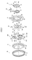
- the seat reclining device 20 is provided with the first bracket 21, the second bracket 31, first to third poles 40A to 40C, a cam 50, a spiral spring 60 that biases the cam 50, a cover 70 that covers the spiral spring 60, and a holding member 80 that holds the first and second brackets 21 and 31.
- the seat reclining device 20 is provided with a ball cam 90 for suppressing an extra movement of the first pole 40A.
- the cam 50, the spiral spring 60, the first to third poles 40A to 40C, and the ball cam 90 constitute the cam mechanism that is described above.
- the cam 50 is arranged between the first and second brackets 21 and 31 (refer to Fig. 2 ).
- the cam 50 has a cam main body portion 51, three pole engagement portions 52, and two spring engagement portions 53 that are engaged with an inner engagement portion 63 (refer to Fig. 3 ) of the spiral spring 60.
- the three pole engagement portions 52 are respectively engaged with the first to third poles 40A to 40C.
- the pole engagement portions 52 are disposed on one surface (first surface 50a) of the cam 50.
- the spring engagement portions 53 are disposed on the other surface (second surface 50b (refer to Fig. 2 )) of the cam 50.
- a fitting hole 54 into which the shaft 5 is fitted is disposed in a central portion of the cam main body portion 51.
- the cam 50 rotates in response to the rotation of the shaft 5. Specifically, the cam 50 rotates when the operation lever 5a that is mounted on the shaft 5 is operated.
- first cam portion 55 a "second cam portion 56”
- third cam portion 57 Three cam portions (hereinafter, referred to as a "first cam portion 55", a “second cam portion 56”, and a “third cam portion 57") that abut against cam surfaces 44A to 44C of the respective poles 40A to 40C are disposed at equal angular intervals on a circumferential surface of the cam main body portion 51.
- the cam 50 is biased, by the spiral spring 60, in a predetermined direction of rotation (hereinafter, this direction will be referred to as a "biasing direction RB") with respect to the first bracket 21.
- this direction will be referred to as a "biasing direction RB"
- a biasing force for rotation in the biasing direction RB is applied to the cam 50.
- the first pole 40A is provided with a first block 41A and a second block 42A that are arranged at different levels.
- the first block 41A is arranged radially outward and the second block 42A is arranged radially inward.
- a radially outward end face (end face facing internal teeth 37 of the second bracket 31) of the first block 41A is configured to have an arc shape.
- External teeth 43A that are engaged with the internal teeth 37 of the second bracket 31 are formed on the radially outward end face.
- the first cam surface 44A against which the first cam portion 55 of the cam 50 abuts is formed at a radially inward end (end face on the side opposite to the radially outward end face) of the first block 41 A.
- a concave curved surface portion 45A for accommodating the ball cam 90 is disposed, continuously from the first cam surface 44A, at the radially inward end of the first block 41 A.
- the ball cam 90 is accommodated in a ball cam accommodating chamber S (refer to Fig. 7A ) that is configured to have the concave curved surface portion 45A of the first pole 40A, the first cam portion 55 of the cam 50, and guide surfaces 24 of guide sections 23.
- the second block 42A is arranged on the first surface 50a side of the cam 50.
- the second block 42A is arranged more on the second bracket 31 side than the cam 50 is in a direction along the axis of rotation C2 (refer to Fig. 2 ).
- the second block 42A is arranged for a radially outward end face of the second block 42A to face an outer circumferential portion 35 or an inner circumferential portion 36 of the second bracket 31 (refer to Figs. 6A and 6B ).
- a limiting unit 46A that abuts against the inner circumferential portion 36 of the second bracket 31 and limits an outward movement of the first pole 40A is disposed on the radially outward end face of the second block 42A.
- a cam hole 47A is disposed in a central portion of the second block 42A to penetrate the central portion of the second block 42A in a thickness direction.
- the second pole 40B has substantially the same structure as the first pole 40A.
- the second pole 40B is provided with a first block 41 B that has external teeth 43B and the second cam surface 44B and a second block 42B that has a cam hole 47B.
- a radially outward end face of the second block 42B does not have any structure corresponding to the limiting unit 46A.
- the third pole 40C has the same structure as the second pole 40B.
- the spiral spring 60 has a spiral portion 61, an outer engagement portion 62 that is an outer end of the spiral portion 61, and the inner engagement portion 63 that is an inner end of the spiral portion 61.
- the spiral spring 60 is formed by winding a metal wire into a spiral shape.
- a spiral-shaped part of the metal wire corresponds to the spiral portion 61
- an outer end of the metal wire corresponds to the outer engagement portion 62
- an inner end of the metal wire corresponds to the inner engagement portion 63.
- the outer engagement portion 62 has an extending portion 62b that extends in a radial direction of the spiral shape and an end portion 62a that is bent at a right angle to the extending portion 62b.
- the outer engagement portion 62 is engaged with the first bracket 21.
- the inner engagement portion 63 is engaged with the spring engagement portions 53 of the cam 50.
- the thickness of the spiral spring 60 (dimension along a central axis of the spring) is smaller than the thickness of a main body portion 22 of the first bracket 21 (dimension along the axis of rotation C2).
- the thickness dimension of the spiral spring 60 is equal to or smaller than the dimension that is obtained by subtracting the plate thickness dimension of a cover main body portion 71 from the thickness dimension of the main body portion 22 of the first bracket 21.
- the cover 70 can be mounted on the first bracket 21 for an outer surface 70a of the cover 70 to correspond to an outer surface 22b of the first bracket 21 or to be positioned inside the outer surface 22b of the first bracket 21 (inside along the axis of rotation C2) in the axis of rotation C2 direction.
- the first bracket 21 will be described with reference to Figs. 4A and 4B .
- the first bracket 21 has the main body portion 22 that has a disk shape, the three guide sections 23 that guide movements of the poles 40A, 40B, and 40C, and convex portions 27 for mounting the first bracket 21 on a fixing member.
- the guide sections 23 are disposed to protrude from an inner surface 22a of the main body portion 22.
- the guide sections 23 have the guide surfaces 24 that extend outward and inner side surfaces 23a.
- the cam 50 is accommodated in an area that is surrounded by the inner side surfaces 23a of the three guide sections 23.
- Two of the guide surfaces 24 that face each other in two of the guide sections 23 that are adjacent to each other are parallel to each other, and these guide surfaces 24 constitute a guide groove 26 in conjunction with the inner surface 22a of the main body portion 22.
- the guide grooves 26 guide the poles 40A, 40B, and 40C to be moved in the radial direction.
- the three guide sections 23 have the same shape and are arranged at equal angles in the circumferential direction. In other words, the three guide grooves 26 are arranged at equal angular intervals in the circumferential direction.
- the side opposite to the guide sections 23 is recessed to correspond to the guide sections 23.
- the convex portions 27 are disposed to protrude from the surface on the side opposite to the respective guide grooves 26 (outer surface 22b of the main body portion 22).
- the side opposite to the convex portions 27 is recessed to correspond to the convex portions 27.
- One of the recessed portions that are configured to be on the side opposite to the convex portions 27 is used as an accommodating concave portion 28.
- the end portion 62a of the spiral spring 60 is accommodated in the accommodating concave portion 28.
- the convex portions 27 are inserted into or engaged with holes or notches that are disposed in the fixing member. Then, the convex portions 27 and the fixing member are welded.
- An accommodating portion 25 in which the spiral portion 61 of the spiral spring 60 is accommodated is disposed in a central portion of the main body portion 22.
- the accommodating portion 25 is configured to penetrate the main body portion 22.
- the accommodating portion 25 has an accommodating main body portion 25a that accommodates the spiral portion 61 of the spiral spring 60 and an outer accommodating portion 25b that accommodates the extending portion 62b of the spiral spring 60.
- the outer accommodating portion 25b allows the accommodating portion 25 and the accommodating concave portion 28 to communicate with each other.
- the outer engagement portion 62 of the spiral spring 60 (refer to Fig. 10 ) is engaged from the outer accommodating portion 25b to the accommodating concave portion 28.
- the first bracket 21 is formed by press working.
- the guide sections 23, a recessed structure on the side opposite to the guide sections 23, the convex portions 27, and a recessed structure on the side opposite to the convex portions 27 are formed with one mold set by press working of a metal plate.
- the cover 70 that is mounted on the first bracket 21 has the following configuration.
- the cover 70 (refer to Fig. 3 ) has the cover main body portion 71 that covers the accommodating main body portion 25a of the first bracket 21, a protruding portion 72 that covers the outer accommodating portion 25b, and an abutting portion 73 that is disposed from a circumferential edge of the cover main body portion 71 and is pressed against an inner circumferential surface 25c of the accommodating main body portion 25a.
- the cover main body portion 71 has a substantially circular shape.
- a through-hole 71 a into which the shaft 5 is inserted is disposed in a central portion of the cover main body portion 71.
- the protruding portion 72 protrudes in the radial direction of the cover main body portion 71 from the circumferential edge of the cover main body portion 71.
- the abutting portion 73 is disposed along the circumferential edge of the cover main body portion 71 and to protrude perpendicularly to an outer surface of the cover main body portion 71.
- a mounting structure for the cover 70 will be described with reference to Figs. 5A and 5B .
- Fig. 5A is a plan view, seen from the outer surface 22b side, of the first bracket 21 on which the cover 70 is mounted.
- Fig. 5B is a cross-sectional view of the first bracket 21 taken along line V-V in Fig. 5A .
- the cover 70 is mounted on the accommodating portion 25 of the first bracket 21 by press-fitting.
- the abutting portion 73 is pressed against the inner circumferential surface 25c of the accommodating main body portion 25a of the first bracket 21.
- substantially the entire spiral spring 60 is covered by the cover 70 when the cover 70 is mounted on the accommodating portion 25 of the first bracket 21.
- the spiral portion 61 of the spiral spring 60 is covered by the cover main body portion 71 and the extending portion 62b of the spiral spring 60 is covered by the protruding portion 72 of the cover 70.
- the outer surface 70a of the cover 70 corresponds to the outer surface 22b of the first bracket 21 or is positioned inside the outer surface 22b of the first bracket 21 in a state where the cover 70 is mounted on the accommodating portion 25 of the first bracket 21. In other words, the cover 70 is mounted on the first bracket 21 not to protrude from the outer surface 22b of the first bracket 21.
- the second bracket 31 will be described with reference to Figs. 6A and 6B .
- the second bracket 31 has a disk-shaped main body portion 32 that has an insertion hole 32a into which the shaft 5 is inserted and an outer circumferential wall 33 that is disposed along an outer edge of the main body portion 32.
- the internal teeth 37 that are engaged with the external teeth 43A to external teeth 43C of the first to third poles 40A to 40C are disposed, over the entire circumference, on an inner circumferential surface 33a of the outer circumferential wall 33.
- An outer circumferential surface 33b of the outer circumferential wall 33 is in sliding contact with the holding member 80.
- An outer surface 33c of the outer circumferential wall 33 is in sliding contact with a protrusion 83 of the holding member 80 (refer to Fig. 2 ).
- a substantially circular concave portion 34 is disposed in a central portion of the main body portion 32.
- the concave portion 34 has the outer circumferential portion 35 that has a circumferential surface which has a predetermined first radius and the inner circumferential portion 36 that has a circumferential surface which has a second radius smaller than the first radius.
- the circumferential surface of the outer circumferential portion 35 is a reference plane, the inner circumferential portion 36 protrudes inwardly in the radial direction.
- the outer circumferential portion 35 is configured for the limiting unit 46A of the first pole 40A not to abut against the outer circumferential portion 35. In other words, the outer circumferential portion 35 is configured not to limit the outward movement of the first pole 40A.
- the inner circumferential portion 36 is configured for the limiting unit 46A of the first pole 40A to abut against the inner circumferential portion 36 during the course of the movement of the first pole 40A to an outermost side. In other words, the inner circumferential portion 36 limits the outward movement of the first pole 40A so that the external teeth 43A of the first pole 40A and the internal teeth 37 of the second bracket 31 are not engaged with each other.
- the holding member 80 is provided with a main body portion 81 that has an annular shape and a flange portion 82 that extends from one circumferential edge of the main body portion 81 toward a center section of the main body portion 81.
- the protrusion 83 that protrudes toward an inner side (second bracket 31 side) is disposed in the flange portion 82. The play (margin) of the movement of the second bracket 31 in the axis of rotation C2 direction is adjusted by the protrusion 83.
- the main body portion 81 of the holding member 80 covers an outer circumferential surface 22c of the first bracket 21 and the outer circumferential surface 33b of the second bracket 31.
- the main body portion 81 of the holding member 80 is laser-welded with the outer circumferential surface 22c of the first bracket 21.
- the flange portion 82 of the holding member 80 covers the outer surface 33c of the outer circumferential wall 33 of the second bracket 31 (refer to Fig. 2 ). In this manner, the holding member 80 holds the first bracket 21 and the second bracket 31 by maintaining a predetermined distance between the first bracket 21 and the second bracket 31 in the axis of rotation C2 direction.
- Figs. 7A to 7C are schematic cross-sectional diagrams taken along line VII-VII in Fig. 2 .
- the guide sections 23 and the holding member 80 are not illustrated in Figs. 7A to 7C .
- Fig. 7A illustrates a state where the external teeth 43A to 43C of the respective poles 40A to 40C and the internal teeth 37 of the second bracket 31 are engaged with each other (hereinafter, "lock state").
- Fig. 7B illustrates a state where the external teeth 43A to 43C of the respective poles 40A to 40C and the internal teeth 37 of the second bracket 31 are not engaged with each other because the respective poles 40A to 40C are maintained at radially inward positions (hereinafter, "unlock state").
- Fig. 7C illustrates a state where the external teeth 43A to 43C of the respective poles 40A to 40C and the internal teeth 37 of the second bracket 31 are not engaged with each other because outward movement of the first pole 40A is limited (hereinafter, "lock limit state").
- the lock state that is illustrated in Fig. 7A is the aspect of the seat reclining device 20 at a time when the seat back 4 is tilted at an angle within a predetermined range with respect to the seat cushion 3 and the operation lever 5a is not operated.
- the movement of the first pole 40A in the radial direction is not limited.
- the biasing force that is applied to the cam 50 causes the cam 50 to rotate in the biasing direction RB, and thus the first to third cam portions 55 to 57 press the first to third cam surfaces 44A to 44C of the respective poles 40A to 40C.
- the respective poles 40A to 40C are pressed outwardly, and thus the external teeth 43A to 43C of the respective poles 40A to 40C are engaged with the internal teeth 37 of the second bracket 31. In other words, the seat reclining device 20 is put into the lock state.
- the unlock state that is illustrated in Fig. 7B is the aspect of the seat reclining device 20 at a time when the operation lever 5a is operated.
- the lock limit state that is illustrated in Fig. 7C is the aspect of the seat reclining device 20 at a time when the seat back 4 is tilted at an angle out of a predetermined range with respect to the seat cushion 3 and the operation lever 5a is not operated.
- the limiting unit 46A of the first pole 40A abuts against the inner circumferential portion 36 of the second bracket 31, and thus the movement of the first pole 40A in the radial direction is limited. Accordingly, the external teeth 43A to 43C of the respective poles 40A to 40C and the internal teeth 37 of the second bracket 31 are separated from each other. In other words, the seat reclining device 20 is put into the lock limit state (state where the rotation of the second bracket 31 is allowed).
- FIG. 8 An example of a mounting structure for the seat reclining device 20 will be described with reference to Fig. 8 .
- Fig. 8 is a cross-sectional view of a mounting portion of the seat reclining device 20 that is mounted on the plate 3a of the seat cushion 3.
- the convex portion 27 of the seat reclining device 20 is inserted into a through-hole 3b that is disposed in the plate 3a of the seat cushion 3. Then, the seat reclining device 20 is mounted on the plate 3a with the outer surface 22b of the first bracket 21 being in contact with the plate 3a.
- the seat reclining device 20 can be mounted in this manner because the outer surface 70a of the cover 70 is configured to correspond to the outer surface 22b of the first bracket 21 or to be positioned inside the outer surface 22b of the first bracket 21.
- the cover 70 protrudes from the outer surface 22b of the first bracket 21, and thus the length (hereinafter, referred to as a "caught length L") of the part of the convex portion 27 that is caught by the plate 3a is shortened and the strength of the mounting structure may be deteriorated.
- the outer surface 70a of the cover 70 corresponds to the outer surface 22b of the first bracket 21 or is positioned inside the outer surface 22b of the first bracket 21 and the cover 70 does not protrude from the outer surface 22b of the first bracket 21, and thus the caught length L is not shortened. Accordingly, the strength of the mounting structure for the seat reclining device 20 is unlikely to be deteriorated.
- the seat reclining device 20 according to this embodiment described above achieves the following effects.
- the seat reclining device 20 is provided with the cover 70 that covers the spiral spring 60, and thus infiltration of dust into the accommodating portion 25 that accommodates the spiral spring 60 can be suppressed.
- the outer surface 70a of the cover 70 corresponds to the outer surface 22b of the first bracket 21 or is positioned inside the outer surface 22b of the first bracket 21 (inside along the axis of rotation C2).
- the cover does not interfere with the mounting of the first bracket 21 on the fixing member.
- the first bracket has a high level of mountability.
- the cover 70 does not protrude from the outer surface 22b of the first bracket 21, and thus the outer surface 22b of the first bracket 21 can be brought into contact with the plate 3a (fixing member) of the seat cushion 3.
- a gap between the first bracket 21 and the plate 3a can be narrowed compared to a case where the cover 70 is mounted to protrude from the outer surface 22b of the first bracket 21.
- the cover 70 has the abutting portion 73 that is pressed against the inner circumferential surface 25c of the accommodating main body portion 25a of the accommodating portion 25. According to this configuration, the cover 70 can be mounted by press-fitting, and thus the mounting of the cover 70 on the first bracket 21 is simplified.
- the accommodating portion 25 has the accommodating main body portion 25a that accommodates the spiral portion 61 of the spiral spring 60 and the outer accommodating portion 25b that accommodates the extending portion 62b of the spiral spring 60.
- the cover 70 has the protruding portion 72 that covers the outer accommodating portion 25b. Accordingly, infiltration of dust from the outer accommodating portion 25b can be suppressed.
- the first bracket 21 has the convex portions 27 for engagement with the fixing member (for example, plate 3a) on the outer surface 22b.
- the seat reclining device 20 has the convex portions 27 for engagement with the fixing member and the outer surface 70a of the cover 70 corresponds to the outer surface 22b of the first bracket 21 or is positioned inside the outer surface 22b of the first bracket 21 (inside along the axis of rotation C2).
- the caught length L of the convex portion 27 is decreased in the structure of the related art, that is, in the structure in which the cover is disposed to protrude from the outer surface of the first bracket.
- the cover 70 does not protrude from the outer surface 22b of the first bracket 21, and thus the caught length L is not decreased.
- the abutting portion 73 of the cover 70 is disposed substantially across the entire circumferential edge of the cover main body portion 71.
- the abutting portion 73 may be disposed at a part of the circumferential edge.
- Fig. 9 illustrates a cover 170 according to a modification example.
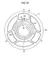
- Fig. 10 is a view illustrating arrangement of an abutting portion 173.
- the abutting portion 73 is disposed at a part corresponding to a part (range illustrated by the arrow in Fig. 10 ) where a gap is made between the spiral portion 61 and the accommodating main body portion 25a of the accommodating portion 25 at the circumferential edge of the cover main body portion 71 in a case where the cover 170 is positioned for a protruding portion 172 to cover the outer accommodating portion 25b of the first bracket 21.
- the abutting portion 173 of the cover 170 is positioned at the part where the gap is made between the spiral portion 61 and the accommodating main body portion 25a of the accommodating portion 25 if the cover 170 is positioned for the protruding portion 172 of the cover 170 to cover the outer accommodating portion 25b of the first bracket 21.
- the protruding portion 172 is absent in the cover 170, the positioning of the cover 170 has to be performed visually and the operation becomes time-consuming.
- the mounting of the cover 170 is facilitated without such troubles.
- the rear rotation direction RX of the second bracket 31 and the biasing direction RB of the cam 50 at a time when the seat back 4 falls to a rear side correspond to each other.
- these directions may also differ from each other.
- the rear rotation direction RX of the second bracket 31 and the biasing direction RB of the cam 50 at a time when the seat back 4 falls to a rear side may be configured to be opposite to each other.
- the three poles 40A, 40B, and 40C are arranged in the first bracket 21.
- the number of the poles is not limited.
- the poles may have different shapes insofar as the poles are configured to be operated in response to each other. Also, the poles may have the same shape.
- the first bracket 21 is fixed to the seat cushion 3 side and the second bracket 31 is fixed to the seat back 4 side.
- this fixing relationship may be the other way around.
- the first bracket 21 may be fixed to the seat back 4 side and the second bracket 31 may be fixed to the seat cushion 3 side.
Landscapes
- Engineering & Computer Science (AREA)
- Aviation & Aerospace Engineering (AREA)
- Transportation (AREA)
- Mechanical Engineering (AREA)
- Chairs For Special Purposes, Such As Reclining Chairs (AREA)
- Seats For Vehicles (AREA)
Abstract
Description
- This disclosure relates to a seat reclining device.
- A device that is described in, for example,
JP 2013-100021A - The seat reclining device is provided with a first bracket that is mounted on the seat cushion, a cam that rotates with respect to the first bracket, a pole that is moved in a radial direction of the first bracket by the rotation of the cam, and a second bracket that is mounted on the seat back and rotates with respect to the first bracket. The pole is moved outwardly by the rotation of the cam and external teeth of the pole are engaged with internal teeth that are disposed on an outer circumferential wall of the second bracket so that the rotation of the second bracket is blocked. In this manner, the second bracket is maintained at a predetermined angle with respect to the first bracket.
- In addition, the cam is biased, by a spiral spring, in a predetermined direction of rotation so that the engagement between the external teeth of the pole and the internal teeth of the second bracket is maintained. The spiral spring is, for example, accommodated in an accommodating portion that is disposed in the first bracket.
- In Reference 1, the accommodating portion is open to an outer side. Accordingly, dust or the like may infiltrate into the accommodating portion. Regarding this point, techniques for covering the spiral spring by using a cover have been known (refer to
JP 2013-215269A - In the case of Reference 2, however, the cover is mounted outside the first bracket, and thus it is difficult to mount the first bracket on a fixing member (for example, a frame that constitutes the seat cushion).
- Thus, a need exists for a seat reclining device that has a high level of bracket mountability.
- A seat reclining device according to an aspect of this disclosure includes a first bracket that has an accommodating portion which is open to an outer side of a seat in a width direction, a second bracket that rotates with respect to the first bracket, a cam that rotates with respect to the first bracket, a spring that is accommodated in the accommodating portion of the first bracket and biases the cam, a pole that is moved in a radial direction of the first bracket based on the rotation of the cam and is engaged with the second bracket, and a cover that covers the spring, in which the cover is mounted on the accommodating portion and an outer surface of the cover on the outer side of the seat in the width direction corresponds to an outer surface of the first bracket on the outer side of the seat in the width direction or is positioned inside the outer surface of the first bracket in the width direction of the seat.
- According to this configuration, the outer surface of the cover corresponds to the outer surface of the first bracket or is positioned inside the outer surface of the first bracket, and thus the cover does not interfere with mounting of the first bracket on a fixing member. In other words, the first bracket has a high level of mountability.
- In the seat reclining device described above, the cover may include an abutting portion that is pressed against an inner circumferential surface of the accommodating portion. According to this configuration, the cover can be mounted by press-fitting, and thus mounting of the cover on the first bracket is simplified.
- In the seat reclining device described above, the spring may be a spiral spring that has a spiral portion and an extending portion which extends radially outward from the spiral portion, the accommodating portion may have an accommodating main body portion that accommodates the spiral portion and an outer accommodating portion that accommodates the extending portion, and the cover may include a protruding portion that covers the outer accommodating portion. According to this configuration, infiltration of dust from the outer accommodating portion can be suppressed.
- In the seat reclining device described above, the abutting portion may be disposed at a part corresponding to a part where a gap is made between the spiral portion of the spring and the accommodating main body portion of the accommodating portion in a case where the cover is positioned for the protruding portion to cover the outer accommodating portion.
- According to this configuration, the abutting portion of the cover is positioned at the part where the gap is made between the spiral portion of the spring and the accommodating main body portion of the accommodating portion if the cover is positioned for the protruding portion of the cover to cover the outer accommodating portion of the first bracket. In a case where the protruding portion is absent in the cover, the positioning of the cover has to be performed visually and the operation becomes time-consuming. However, according to this configuration, the mounting of the cover is facilitated without such troubles.
- In the seat reclining device described above, the first bracket may be mounted on a fixing member and a convex portion for engagement with the fixing member may be disposed on the outer surface of the first bracket.
- In other words, this seat reclining device has the convex portion for engagement with the fixing member and the outer surface of the cover corresponds to the outer surface of the first bracket or is positioned inside the outer surface of the first bracket.
- In a configuration in which the first bracket is mounted on the fixing member via the convex portion, it is preferable to ensure a caught length of the convex portion. The caught length is decreased in the structure of the related art, that is, in the structure in which the cover is disposed to protrude from the outer surface of the first bracket. However, in the seat reclining device having the configuration described above, the cover does not protrude from the outer surface of the first bracket, and thus the caught length is not decreased.
- The seat reclining device having the configuration described above has a high level of bracket mountability.
- The foregoing and additional features and characteristics of this disclosure will become more apparent from the following detailed description considered with the reference to the accompanying drawings, wherein:
-
Fig. 1 is a side view of a seat that is provided with a seat reclining device; -
Fig. 2 is a cross-sectional view of the seat reclining device taken along line II-II inFig. 1 ; -
Fig. 3 is an exploded perspective view of the seat reclining device; -
Fig. 4A is a plan view (view from inside) of a first bracket andFig. 4B is a side view of the first bracket; -
Fig. 5A is a plan view (view from outside) of the first bracket on which a cover is mounted andFig. 5B is a cross-sectional view taken along line V-V inFig. 5A ; -
Fig. 6A is a plan view of a second bracket andFig. 6B is a cross-sectional view taken along line VI-VI inFig. 6A ; -
Figs. 7A to 7C are schematic cross-sectional diagrams taken along line VII-VII inFig. 2 ,Fig. 7A is a schematic diagram illustrating a lock state,Fig. 7B is a schematic diagram illustrating an unlock state, andFig. 7C is a schematic diagram illustrating a lock limit state; -
Fig. 8 is an enlarged view of a mounting portion of the seat reclining device that is mounted on a fixing member; -
Fig. 9 is a perspective view of a cover according to a modification example; and -
Fig. 10 is a plan view illustrating arrangement of an abutting portion of the cover according to the modification example with regard to the first bracket. - A seat reclining device according to an embodiment will be described with reference to
Figs. 1 to 8 . - As illustrated in
Fig. 1 , a seat recliningdevice 20 is applied to a seat 2 that is disposed on a vehicle floor 1 or the like. The seat 2 relating to this application is provided with, for example, aseat cushion 3 that constitutes a seat surface and a seat back 4 that constitutes a backrest. The seat back 4 is rotatable and can be maintained at a predetermined angle with respect to theseat cushion 3. - The seat back 4 is mounted on the
seat cushion 3 via the seat recliningdevice 20. The seat recliningdevice 20 maintains the seat back 4 at a predetermined angle with respect to theseat cushion 3. - As illustrated in
Fig. 2 , one of rotating bodies (one of first andsecond brackets 21 and 31 (described later)) of the seat recliningdevice 20 is fixed to aplate 3a that is mounted on theseat cushion 3. The other rotating body (the other one of the first andsecond brackets 21 and 31 (described later)) of the seat recliningdevice 20 is fixed to aplate 4a that is mounted on the seat back 4. In the following description of this embodiment, thefirst bracket 21 is fixed to theplate 3a on theseat cushion 3 side and thesecond bracket 31 is fixed to theplate 4a on the seat back 4 side as illustrated inFig. 2 . - In addition, a
shaft 5 penetrates a central portion of theseat reclining device 20. Theshaft 5 operates a cam mechanism that is disposed in theseat reclining device 20. Anoperation lever 5a for rotating theshaft 5 is mounted on an end portion of theshaft 5. - In a state where the
seat reclining device 20 is mounted on the seat 2, an axis of rotation C1 of theshaft 5 and an axis of rotation C2 of the seat reclining device 20 (axes of rotation of thefirst bracket 21 and the second bracket 31) correspond to each other. - In the following description, a direction along a circumference whose central axis is the axis of rotation C2 of the
seat reclining device 20 will be referred to as a circumferential direction and a direction (normal direction) that is perpendicular to the axis of rotation C2 will be referred to as a radial direction. In addition, a direction in which thesecond bracket 31 rotates as a result of backward falling of the seat back 4 will be referred to as a rear rotation direction RX. - A configuration of the
seat reclining device 20 will be described with reference toFig. 3 . - As illustrated in
Fig. 3 , theseat reclining device 20 is provided with thefirst bracket 21, thesecond bracket 31, first tothird poles 40A to 40C, acam 50, aspiral spring 60 that biases thecam 50, acover 70 that covers thespiral spring 60, and a holdingmember 80 that holds the first andsecond brackets seat reclining device 20 is provided with aball cam 90 for suppressing an extra movement of thefirst pole 40A. Thecam 50, thespiral spring 60, the first tothird poles 40A to 40C, and theball cam 90 constitute the cam mechanism that is described above. - The
cam 50 is arranged between the first andsecond brackets 21 and 31 (refer toFig. 2 ). - The
cam 50 has a cammain body portion 51, threepole engagement portions 52, and two spring engagement portions 53 that are engaged with an inner engagement portion 63 (refer toFig. 3 ) of thespiral spring 60. The threepole engagement portions 52 are respectively engaged with the first tothird poles 40A to 40C. Thepole engagement portions 52 are disposed on one surface (first surface 50a) of thecam 50. The spring engagement portions 53 are disposed on the other surface (second surface 50b (refer toFig. 2 )) of thecam 50. - A
fitting hole 54 into which theshaft 5 is fitted is disposed in a central portion of the cammain body portion 51. Thecam 50 rotates in response to the rotation of theshaft 5. Specifically, thecam 50 rotates when theoperation lever 5a that is mounted on theshaft 5 is operated. - Three cam portions (hereinafter, referred to as a "
first cam portion 55", a "second cam portion 56", and a "third cam portion 57") that abut against cam surfaces 44A to 44C of therespective poles 40A to 40C are disposed at equal angular intervals on a circumferential surface of the cammain body portion 51. - The
cam 50 is biased, by thespiral spring 60, in a predetermined direction of rotation (hereinafter, this direction will be referred to as a "biasing direction RB") with respect to thefirst bracket 21. In other words, a biasing force for rotation in the biasing direction RB is applied to thecam 50. - The
first pole 40A is provided with afirst block 41A and asecond block 42A that are arranged at different levels. Thefirst block 41A is arranged radially outward and thesecond block 42A is arranged radially inward. - A radially outward end face (end face facing
internal teeth 37 of the second bracket 31) of thefirst block 41A is configured to have an arc shape.External teeth 43A that are engaged with theinternal teeth 37 of thesecond bracket 31 are formed on the radially outward end face. - The
first cam surface 44A against which thefirst cam portion 55 of thecam 50 abuts is formed at a radially inward end (end face on the side opposite to the radially outward end face) of thefirst block 41 A. - In addition, a concave curved surface portion 45A for accommodating the
ball cam 90 is disposed, continuously from thefirst cam surface 44A, at the radially inward end of thefirst block 41 A. Theball cam 90 is accommodated in a ball cam accommodating chamber S (refer toFig. 7A ) that is configured to have the concave curved surface portion 45A of thefirst pole 40A, thefirst cam portion 55 of thecam 50, and guidesurfaces 24 ofguide sections 23. - The
second block 42A is arranged on thefirst surface 50a side of thecam 50. In other words, thesecond block 42A is arranged more on thesecond bracket 31 side than thecam 50 is in a direction along the axis of rotation C2 (refer toFig. 2 ). Also, thesecond block 42A is arranged for a radially outward end face of thesecond block 42A to face an outercircumferential portion 35 or an innercircumferential portion 36 of the second bracket 31 (refer toFigs. 6A and 6B ). - A limiting
unit 46A that abuts against the innercircumferential portion 36 of thesecond bracket 31 and limits an outward movement of thefirst pole 40A is disposed on the radially outward end face of thesecond block 42A. In addition, acam hole 47A is disposed in a central portion of thesecond block 42A to penetrate the central portion of thesecond block 42A in a thickness direction. - The
second pole 40B has substantially the same structure as thefirst pole 40A. - As is the case with the
first pole 40A, thesecond pole 40B is provided with afirst block 41 B that hasexternal teeth 43B and thesecond cam surface 44B and asecond block 42B that has acam hole 47B. However, a radially outward end face of thesecond block 42B does not have any structure corresponding to the limitingunit 46A. Thethird pole 40C has the same structure as thesecond pole 40B. - The
spiral spring 60 has aspiral portion 61, anouter engagement portion 62 that is an outer end of thespiral portion 61, and theinner engagement portion 63 that is an inner end of thespiral portion 61. - Specifically, the
spiral spring 60 is formed by winding a metal wire into a spiral shape. A spiral-shaped part of the metal wire corresponds to thespiral portion 61, an outer end of the metal wire corresponds to theouter engagement portion 62, and an inner end of the metal wire corresponds to theinner engagement portion 63. Theouter engagement portion 62 has an extendingportion 62b that extends in a radial direction of the spiral shape and anend portion 62a that is bent at a right angle to the extendingportion 62b. Theouter engagement portion 62 is engaged with thefirst bracket 21. Theinner engagement portion 63 is engaged with the spring engagement portions 53 of thecam 50. - The thickness of the spiral spring 60 (dimension along a central axis of the spring) is smaller than the thickness of a
main body portion 22 of the first bracket 21 (dimension along the axis of rotation C2). Specifically, the thickness dimension of thespiral spring 60 is equal to or smaller than the dimension that is obtained by subtracting the plate thickness dimension of a covermain body portion 71 from the thickness dimension of themain body portion 22 of thefirst bracket 21. Accordingly, thecover 70 can be mounted on thefirst bracket 21 for anouter surface 70a of thecover 70 to correspond to anouter surface 22b of thefirst bracket 21 or to be positioned inside theouter surface 22b of the first bracket 21 (inside along the axis of rotation C2) in the axis of rotation C2 direction. - The
first bracket 21 will be described with reference toFigs. 4A and 4B . - As illustrated in
Figs. 4A and 4B , thefirst bracket 21 has themain body portion 22 that has a disk shape, the threeguide sections 23 that guide movements of thepoles convex portions 27 for mounting thefirst bracket 21 on a fixing member. - The
guide sections 23 are disposed to protrude from aninner surface 22a of themain body portion 22. - The
guide sections 23 have the guide surfaces 24 that extend outward andinner side surfaces 23a. Thecam 50 is accommodated in an area that is surrounded by the inner side surfaces 23a of the threeguide sections 23. - Two of the guide surfaces 24 that face each other in two of the
guide sections 23 that are adjacent to each other are parallel to each other, and these guide surfaces 24 constitute aguide groove 26 in conjunction with theinner surface 22a of themain body portion 22. Theguide grooves 26 guide thepoles - The three
guide sections 23 have the same shape and are arranged at equal angles in the circumferential direction. In other words, the threeguide grooves 26 are arranged at equal angular intervals in the circumferential direction. The side opposite to the guide sections 23 (outer surface 22b side of the first bracket 21) is recessed to correspond to theguide sections 23. - The
convex portions 27 are disposed to protrude from the surface on the side opposite to the respective guide grooves 26 (outer surface 22b of the main body portion 22). The side opposite to the convex portions 27 (inner surface 22a side of the first bracket 21) is recessed to correspond to theconvex portions 27. One of the recessed portions that are configured to be on the side opposite to theconvex portions 27 is used as an accommodatingconcave portion 28. Theend portion 62a of thespiral spring 60 is accommodated in the accommodatingconcave portion 28. - When the
first bracket 21 is mounted on the fixing member (for example, theplate 3a), theconvex portions 27 are inserted into or engaged with holes or notches that are disposed in the fixing member. Then, theconvex portions 27 and the fixing member are welded. - An
accommodating portion 25 in which thespiral portion 61 of thespiral spring 60 is accommodated is disposed in a central portion of themain body portion 22. - The
accommodating portion 25 is configured to penetrate themain body portion 22. Theaccommodating portion 25 has an accommodatingmain body portion 25a that accommodates thespiral portion 61 of thespiral spring 60 and an outeraccommodating portion 25b that accommodates the extendingportion 62b of thespiral spring 60. The outeraccommodating portion 25b allows theaccommodating portion 25 and the accommodatingconcave portion 28 to communicate with each other. Theouter engagement portion 62 of the spiral spring 60 (refer toFig. 10 ) is engaged from the outeraccommodating portion 25b to the accommodatingconcave portion 28. - The
first bracket 21 is formed by press working. - For example, the
guide sections 23, a recessed structure on the side opposite to theguide sections 23, theconvex portions 27, and a recessed structure on the side opposite to theconvex portions 27 are formed with one mold set by press working of a metal plate. - The
cover 70 that is mounted on thefirst bracket 21 has the following configuration. - The cover 70 (refer to
Fig. 3 ) has the covermain body portion 71 that covers the accommodatingmain body portion 25a of thefirst bracket 21, a protrudingportion 72 that covers the outeraccommodating portion 25b, and an abuttingportion 73 that is disposed from a circumferential edge of the covermain body portion 71 and is pressed against an innercircumferential surface 25c of the accommodatingmain body portion 25a. - The cover
main body portion 71 has a substantially circular shape. A through-hole 71 a into which theshaft 5 is inserted is disposed in a central portion of the covermain body portion 71. - The protruding
portion 72 protrudes in the radial direction of the covermain body portion 71 from the circumferential edge of the covermain body portion 71. The abuttingportion 73 is disposed along the circumferential edge of the covermain body portion 71 and to protrude perpendicularly to an outer surface of the covermain body portion 71. - A mounting structure for the
cover 70 will be described with reference toFigs. 5A and 5B . -
Fig. 5A is a plan view, seen from theouter surface 22b side, of thefirst bracket 21 on which thecover 70 is mounted.Fig. 5B is a cross-sectional view of thefirst bracket 21 taken along line V-V inFig. 5A . - The
cover 70 is mounted on theaccommodating portion 25 of thefirst bracket 21 by press-fitting. When thecover 70 is mounted on thefirst bracket 21, the abuttingportion 73 is pressed against the innercircumferential surface 25c of the accommodatingmain body portion 25a of thefirst bracket 21. - As illustrated in
Fig. 5A , substantially theentire spiral spring 60 is covered by thecover 70 when thecover 70 is mounted on theaccommodating portion 25 of thefirst bracket 21. Thespiral portion 61 of thespiral spring 60 is covered by the covermain body portion 71 and the extendingportion 62b of thespiral spring 60 is covered by the protrudingportion 72 of thecover 70. - As illustrated in
Fig. 5B , theouter surface 70a of thecover 70 corresponds to theouter surface 22b of thefirst bracket 21 or is positioned inside theouter surface 22b of thefirst bracket 21 in a state where thecover 70 is mounted on theaccommodating portion 25 of thefirst bracket 21. In other words, thecover 70 is mounted on thefirst bracket 21 not to protrude from theouter surface 22b of thefirst bracket 21. - The
second bracket 31 will be described with reference toFigs. 6A and 6B . - As illustrated in
Figs. 6A and 6B , thesecond bracket 31 has a disk-shapedmain body portion 32 that has aninsertion hole 32a into which theshaft 5 is inserted and an outercircumferential wall 33 that is disposed along an outer edge of themain body portion 32. - The
internal teeth 37 that are engaged with theexternal teeth 43A toexternal teeth 43C of the first tothird poles 40A to 40C are disposed, over the entire circumference, on an innercircumferential surface 33a of the outercircumferential wall 33. - An outer
circumferential surface 33b of the outercircumferential wall 33 is in sliding contact with the holdingmember 80. Anouter surface 33c of the outercircumferential wall 33 is in sliding contact with aprotrusion 83 of the holding member 80 (refer toFig. 2 ). - A substantially circular
concave portion 34 is disposed in a central portion of themain body portion 32. - The
concave portion 34 has the outercircumferential portion 35 that has a circumferential surface which has a predetermined first radius and the innercircumferential portion 36 that has a circumferential surface which has a second radius smaller than the first radius. When the circumferential surface of the outercircumferential portion 35 is a reference plane, the innercircumferential portion 36 protrudes inwardly in the radial direction. - The outer
circumferential portion 35 is configured for the limitingunit 46A of thefirst pole 40A not to abut against the outercircumferential portion 35. In other words, the outercircumferential portion 35 is configured not to limit the outward movement of thefirst pole 40A. - The inner
circumferential portion 36 is configured for the limitingunit 46A of thefirst pole 40A to abut against the innercircumferential portion 36 during the course of the movement of thefirst pole 40A to an outermost side. In other words, the innercircumferential portion 36 limits the outward movement of thefirst pole 40A so that theexternal teeth 43A of thefirst pole 40A and theinternal teeth 37 of thesecond bracket 31 are not engaged with each other. - Next, the holding
member 80 will be described. - As illustrated in
Fig. 3 , the holdingmember 80 is provided with amain body portion 81 that has an annular shape and aflange portion 82 that extends from one circumferential edge of themain body portion 81 toward a center section of themain body portion 81. Theprotrusion 83 that protrudes toward an inner side (second bracket 31 side) is disposed in theflange portion 82. The play (margin) of the movement of thesecond bracket 31 in the axis of rotation C2 direction is adjusted by theprotrusion 83. - The
main body portion 81 of the holdingmember 80 covers an outercircumferential surface 22c of thefirst bracket 21 and the outercircumferential surface 33b of thesecond bracket 31. In addition, themain body portion 81 of the holdingmember 80 is laser-welded with the outercircumferential surface 22c of thefirst bracket 21. Theflange portion 82 of the holdingmember 80 covers theouter surface 33c of the outercircumferential wall 33 of the second bracket 31 (refer toFig. 2 ). In this manner, the holdingmember 80 holds thefirst bracket 21 and thesecond bracket 31 by maintaining a predetermined distance between thefirst bracket 21 and thesecond bracket 31 in the axis of rotation C2 direction. - An operation of the
seat reclining device 20 will be described with reference toFigs. 7A to 7C . -
Figs. 7A to 7C are schematic cross-sectional diagrams taken along line VII-VII inFig. 2 . Theguide sections 23 and the holdingmember 80 are not illustrated inFigs. 7A to 7C . -
Fig. 7A illustrates a state where theexternal teeth 43A to 43C of therespective poles 40A to 40C and theinternal teeth 37 of thesecond bracket 31 are engaged with each other (hereinafter, "lock state"). -
Fig. 7B illustrates a state where theexternal teeth 43A to 43C of therespective poles 40A to 40C and theinternal teeth 37 of thesecond bracket 31 are not engaged with each other because therespective poles 40A to 40C are maintained at radially inward positions (hereinafter, "unlock state"). -
Fig. 7C illustrates a state where theexternal teeth 43A to 43C of therespective poles 40A to 40C and theinternal teeth 37 of thesecond bracket 31 are not engaged with each other because outward movement of thefirst pole 40A is limited (hereinafter, "lock limit state"). - Next, an operation of the cam mechanism in each of the states of the
seat reclining device 20 will be described. - The lock state that is illustrated in
Fig. 7A is the aspect of theseat reclining device 20 at a time when the seat back 4 is tilted at an angle within a predetermined range with respect to theseat cushion 3 and theoperation lever 5a is not operated. - When the seat back 4 is tilted at an angle within a predetermined range with respect to the
seat cushion 3, that is, when the outercircumferential portion 35 of thesecond bracket 31 is at a position corresponding to the limitingunit 46A of thefirst pole 40A, the movement of thefirst pole 40A in the radial direction is not limited. - When the
operation lever 5a is not operated, that is, when a force in the direction opposite to the biasing direction RB is not applied to thecam 50, the biasing force that is applied to thecam 50 causes thecam 50 to rotate in the biasing direction RB, and thus the first tothird cam portions 55 to 57 press the first to third cam surfaces 44A to 44C of therespective poles 40A to 40C. As a result, therespective poles 40A to 40C are pressed outwardly, and thus theexternal teeth 43A to 43C of therespective poles 40A to 40C are engaged with theinternal teeth 37 of thesecond bracket 31. In other words, theseat reclining device 20 is put into the lock state. - The unlock state that is illustrated in
Fig. 7B is the aspect of theseat reclining device 20 at a time when theoperation lever 5a is operated. - When the
cam 50 is allowed to rotate in the direction opposite to the biasing direction RB by the operation of theoperation lever 5a, therespective poles 40A to 40C are moved radially inward, and thus theexternal teeth 43A to 43C of therespective poles 40A to 40C and theinternal teeth 37 of thesecond bracket 31 are separated from each other. In this manner, theseat reclining device 20 is put into the unlock state. - The lock limit state that is illustrated in
Fig. 7C is the aspect of theseat reclining device 20 at a time when the seat back 4 is tilted at an angle out of a predetermined range with respect to theseat cushion 3 and theoperation lever 5a is not operated. - When the seat back 4 is tilted at an angle out of a predetermined range with respect to the
seat cushion 3, that is, when the innercircumferential portion 36 of thesecond bracket 31 is at a position corresponding to the limitingunit 46A of thefirst pole 40A, the limitingunit 46A of thefirst pole 40A abuts against the innercircumferential portion 36 of thesecond bracket 31, and thus the movement of thefirst pole 40A in the radial direction is limited. Accordingly, theexternal teeth 43A to 43C of therespective poles 40A to 40C and theinternal teeth 37 of thesecond bracket 31 are separated from each other. In other words, theseat reclining device 20 is put into the lock limit state (state where the rotation of thesecond bracket 31 is allowed). - An example of a mounting structure for the
seat reclining device 20 will be described with reference toFig. 8 . -
Fig. 8 is a cross-sectional view of a mounting portion of theseat reclining device 20 that is mounted on theplate 3a of theseat cushion 3. - In this mounting structure, the
convex portion 27 of theseat reclining device 20 is inserted into a through-hole 3b that is disposed in theplate 3a of theseat cushion 3. Then, theseat reclining device 20 is mounted on theplate 3a with theouter surface 22b of thefirst bracket 21 being in contact with theplate 3a. - The
seat reclining device 20 can be mounted in this manner because theouter surface 70a of thecover 70 is configured to correspond to theouter surface 22b of thefirst bracket 21 or to be positioned inside theouter surface 22b of thefirst bracket 21. - In the
seat reclining device 20 of the related art, thecover 70 protrudes from theouter surface 22b of thefirst bracket 21, and thus the length (hereinafter, referred to as a "caught length L") of the part of theconvex portion 27 that is caught by theplate 3a is shortened and the strength of the mounting structure may be deteriorated. However, in theseat reclining device 20 according to this embodiment, theouter surface 70a of thecover 70 corresponds to theouter surface 22b of thefirst bracket 21 or is positioned inside theouter surface 22b of thefirst bracket 21 and thecover 70 does not protrude from theouter surface 22b of thefirst bracket 21, and thus the caught length L is not shortened. Accordingly, the strength of the mounting structure for theseat reclining device 20 is unlikely to be deteriorated. - The
seat reclining device 20 according to this embodiment described above achieves the following effects. - (1) If, for example, dust gets into the metal wire that constitutes the
spiral spring 60 or dust accumulates between thespiral spring 60 and theaccommodating portion 25, the movement of thespiral spring 60 is limited and the operation of theseat reclining device 20 is hindered. However, theseat reclining device 20 according to this embodiment is provided with thecover 70 that covers thespiral spring 60, and thus infiltration of dust into theaccommodating portion 25 that accommodates thespiral spring 60 can be suppressed. - In addition, the
outer surface 70a of thecover 70 corresponds to theouter surface 22b of thefirst bracket 21 or is positioned inside theouter surface 22b of the first bracket 21 (inside along the axis of rotation C2). - Accordingly, the cover does not interfere with the mounting of the
first bracket 21 on the fixing member. In other words, the first bracket has a high level of mountability. - In addition, the
cover 70 does not protrude from theouter surface 22b of thefirst bracket 21, and thus theouter surface 22b of thefirst bracket 21 can be brought into contact with theplate 3a (fixing member) of theseat cushion 3. In other words, a gap between thefirst bracket 21 and theplate 3a can be narrowed compared to a case where thecover 70 is mounted to protrude from theouter surface 22b of thefirst bracket 21. - (2) In the embodiment described above, the
cover 70 has the abuttingportion 73 that is pressed against the innercircumferential surface 25c of the accommodatingmain body portion 25a of theaccommodating portion 25. According to this configuration, thecover 70 can be mounted by press-fitting, and thus the mounting of thecover 70 on thefirst bracket 21 is simplified. - (3) In the embodiment described above, the
accommodating portion 25 has the accommodatingmain body portion 25a that accommodates thespiral portion 61 of thespiral spring 60 and the outeraccommodating portion 25b that accommodates the extendingportion 62b of thespiral spring 60. Thecover 70 has the protrudingportion 72 that covers the outeraccommodating portion 25b. Accordingly, infiltration of dust from the outeraccommodating portion 25b can be suppressed. - (4) In the embodiment described above, the
first bracket 21 has theconvex portions 27 for engagement with the fixing member (for example,plate 3a) on theouter surface 22b. - In other words, the
seat reclining device 20 has theconvex portions 27 for engagement with the fixing member and theouter surface 70a of thecover 70 corresponds to theouter surface 22b of thefirst bracket 21 or is positioned inside theouter surface 22b of the first bracket 21 (inside along the axis of rotation C2). - In this configuration in which the
first bracket 21 is mounted on the fixing member via theconvex portions 27, it is preferable to ensure the caught length L of theconvex portion 27. The caught length is decreased in the structure of the related art, that is, in the structure in which the cover is disposed to protrude from the outer surface of the first bracket. However, in theseat reclining device 20 having the configuration described above, thecover 70 does not protrude from theouter surface 22b of thefirst bracket 21, and thus the caught length L is not decreased. - The embodiment described above can also be changed as follows.
- In the embodiment described above, the abutting
portion 73 of thecover 70 is disposed substantially across the entire circumferential edge of the covermain body portion 71. However, the abuttingportion 73 may be disposed at a part of the circumferential edge. -
Fig. 9 illustrates acover 170 according to a modification example.Fig. 10 is a view illustrating arrangement of anabutting portion 173. - In this
cover 170, the abuttingportion 73 is disposed at a part corresponding to a part (range illustrated by the arrow inFig. 10 ) where a gap is made between thespiral portion 61 and the accommodatingmain body portion 25a of theaccommodating portion 25 at the circumferential edge of the covermain body portion 71 in a case where thecover 170 is positioned for a protrudingportion 172 to cover the outeraccommodating portion 25b of thefirst bracket 21. - According to this configuration, the abutting
portion 173 of thecover 170 is positioned at the part where the gap is made between thespiral portion 61 and the accommodatingmain body portion 25a of theaccommodating portion 25 if thecover 170 is positioned for the protrudingportion 172 of thecover 170 to cover the outeraccommodating portion 25b of thefirst bracket 21. In a case where the protrudingportion 172 is absent in thecover 170, the positioning of thecover 170 has to be performed visually and the operation becomes time-consuming. However, according to this configuration, the mounting of thecover 170 is facilitated without such troubles. - In the embodiment described above, the rear rotation direction RX of the
second bracket 31 and the biasing direction RB of thecam 50 at a time when the seat back 4 falls to a rear side correspond to each other. However, these directions may also differ from each other. In other words, the rear rotation direction RX of thesecond bracket 31 and the biasing direction RB of thecam 50 at a time when the seat back 4 falls to a rear side may be configured to be opposite to each other. - In the embodiment described above, the three
poles first bracket 21. However, the number of the poles is not limited. In a case where a plurality of the poles are arranged, the poles may have different shapes insofar as the poles are configured to be operated in response to each other. Also, the poles may have the same shape. - In the embodiment described above, the
first bracket 21 is fixed to theseat cushion 3 side and thesecond bracket 31 is fixed to the seat back 4 side. However, this fixing relationship may be the other way around. In other words, thefirst bracket 21 may be fixed to the seat back 4 side and thesecond bracket 31 may be fixed to theseat cushion 3 side. - The principles, preferred embodiment and mode of operation of the present invention have been described in the foregoing specification. However, the invention which is intended to be protected is not to be construed as limited to the particular embodiments disclosed. Further, the embodiments described herein are to be regarded as illustrative rather than restrictive. Variations and changes may be made by others, and equivalents employed. Accordingly, it is expressly intended that all such variations, changes and equivalents which fall within the scope of the present invention as defined in the claims, be embraced thereby.
Claims (5)
- A seat reclining device (20) comprising:a first bracket (21) that includes an accommodating portion (25) which is open to an outer side of a seat (2) in a width direction;a second bracket (31) that rotates with respect to the first bracket;a cam (50) that rotates with respect to the first bracket;a spring (60) that is accommodated in the accommodating portion of the first bracket and biases the cam;a pole (40A, 40B, 40C) that is moved in a radial direction of the first bracket based on the rotation of the cam and is engaged with the second bracket; anda cover (70) that covers the spring,wherein the cover (70) is mounted on the accommodating portion (25) and an outer surface (70a) of the cover (70) on the outer side of the seat in the width direction corresponds to an outer surface (22b) of the first bracket (21) on the outer side of the seat in the width direction or is positioned inside the outer surface (22b) of the first bracket (21) in the width direction of the seat.
- The seat reclining device according to claim 1,
wherein the cover (70) includes an abutting portion (73) that is pressed against an inner circumferential surface (25c) of the accommodating portion (25). - The seat reclining device according to claim 2,
wherein the spring (60) is a spiral spring that includes a spiral portion (61) and an extending portion (62b) which extends radially outward from the spiral portion,
wherein the accommodating portion (25) has an accommodating main body portion (25a) that accommodates the spiral portion (61) and an outer accommodating portion (25b) that accommodates the extending portion (62b), and
wherein the cover (70) includes a protruding portion (72) that covers the outer accommodating portion (25b). - The seat reclining device according to claim 3,
wherein the abutting portion (73) is disposed at a part corresponding to a part where a gap is made between the spiral portion (61) of the spring (60) and the accommodating main body portion (250) of the accommodating portion (25) in a case where the cover (70) is positioned for the protruding portion (72) to cover the outer accommodating portion (25b). - The seat reclining device according to any one of claims 1 to 4,
wherein the first bracket (21) is mounted on a fixing member, and
wherein a convex portion (27) for engagement with the fixing member is disposed on the outer surface of the first bracket (21).
Applications Claiming Priority (1)
| Application Number | Priority Date | Filing Date | Title |
|---|---|---|---|
| JP2014033327A JP6384061B2 (en) | 2014-02-24 | 2014-02-24 | Seat reclining device |
Publications (2)
| Publication Number | Publication Date |
|---|---|
| EP2910411A1 true EP2910411A1 (en) | 2015-08-26 |
| EP2910411B1 EP2910411B1 (en) | 2018-09-19 |
Family
ID=52477710
Family Applications (1)
| Application Number | Title | Priority Date | Filing Date |
|---|---|---|---|
| EP15155853.3A Not-in-force EP2910411B1 (en) | 2014-02-24 | 2015-02-20 | Seat reclining device |
Country Status (4)
| Country | Link |
|---|---|
| US (1) | US9573493B2 (en) |
| EP (1) | EP2910411B1 (en) |
| JP (1) | JP6384061B2 (en) |
| CN (1) | CN204472606U (en) |
Families Citing this family (14)
| Publication number | Priority date | Publication date | Assignee | Title |
|---|---|---|---|---|
| JP6237325B2 (en) * | 2014-02-24 | 2017-11-29 | アイシン精機株式会社 | Seat reclining device |
| US9868369B1 (en) * | 2016-07-15 | 2018-01-16 | Ford Global Technologies, Llc | Tip and slide system for a vehicle seat |
| DE102016225834B4 (en) * | 2016-10-04 | 2020-01-09 | Adient Luxembourg Holding S.À R.L. | VEHICLE SEAT, IN PARTICULAR MOTOR VEHICLE SEAT |
| KR102011089B1 (en) * | 2017-12-26 | 2019-08-14 | 현대트랜시스(주) | Seat recliner for vehicle and method for producing the same |
| US11364577B2 (en) | 2019-02-11 | 2022-06-21 | Fisher & Company, Incorporated | Recliner mechanism for seat assembly and method of manufacturing |
| US11845367B2 (en) | 2019-04-18 | 2023-12-19 | Fisher & Company, Incorporated | Recliner heart having lubricant member |
| US11192473B2 (en) | 2019-08-30 | 2021-12-07 | Fisher & Company, Incorporated | Release handle for recliner mechanism of vehicle seat |
| US11607976B2 (en) | 2020-03-06 | 2023-03-21 | Fisher & Company, Incorporated | Recliner mechanism having bracket |
| JP7424197B2 (en) * | 2020-05-13 | 2024-01-30 | トヨタ紡織株式会社 | Vehicle seat reclining device |
| US11766957B2 (en) | 2021-02-16 | 2023-09-26 | Fisher & Company, Incorporated | Release mechanism for seat recliner assembly |
| US11897372B2 (en) | 2021-05-06 | 2024-02-13 | Fisher & Company, Incorporated | Recliner heart having biasing members |
| US11850975B2 (en) | 2021-06-11 | 2023-12-26 | Fisher & Company, Incorporated | Vehicle seat recliner mechanism with welded spring |
| FR3124442B1 (en) * | 2021-06-28 | 2023-06-23 | Faurecia Sieges Dautomobile | Angular adjustment device for a vehicle seat |
| US20260054612A1 (en) * | 2024-08-26 | 2026-02-26 | Lear Corporation | Seat assembly and corresponding latch |
Citations (7)
| Publication number | Priority date | Publication date | Assignee | Title |
|---|---|---|---|---|
| WO2008046004A1 (en) * | 2006-10-12 | 2008-04-17 | Johnson Controls Technology Company | Rotary recliner mechanism |
| FR2920713A1 (en) * | 2007-09-12 | 2009-03-13 | Faurecia Sieges Automobile | MECHANISM FOR ADJUSTING THE TILT OF A MOTOR VEHICLE SEAT |
| DE202010015171U1 (en) * | 2010-06-22 | 2011-02-10 | Keiper Gmbh & Co. Kg | Fitting system for a vehicle seat |
| WO2011160771A1 (en) * | 2010-06-22 | 2011-12-29 | Keiper Gmbh & Co. Kg | Recliner system for a vehicle seat |
| DE102012005697A1 (en) * | 2011-03-22 | 2012-09-27 | Faurecia Sièges d'Automobile | Adjustment mechanism and vehicle seat with such an adjustment mechanism |
| JP2013100021A (en) | 2011-11-08 | 2013-05-23 | Shiroki Corp | Reclining apparatus |
| JP2013215269A (en) | 2012-04-05 | 2013-10-24 | Shiroki Corp | Reclining device |
Family Cites Families (5)
| Publication number | Priority date | Publication date | Assignee | Title |
|---|---|---|---|---|
| JP4032806B2 (en) * | 2002-04-18 | 2008-01-16 | トヨタ紡織株式会社 | Reclining device |
| JP2007151682A (en) * | 2005-12-01 | 2007-06-21 | Aisin Seiki Co Ltd | Vehicle seat reclining device |
| JP5046682B2 (en) * | 2007-02-28 | 2012-10-10 | 富士機工株式会社 | Vehicle seat reclining device |
| JP5309665B2 (en) * | 2008-04-08 | 2013-10-09 | トヨタ紡織株式会社 | Vehicle seat coupling device |
| JP5827118B2 (en) | 2011-12-22 | 2015-12-02 | シロキ工業株式会社 | Reclining device |
-
2014
- 2014-02-24 JP JP2014033327A patent/JP6384061B2/en not_active Expired - Fee Related
-
2015
- 2015-02-17 CN CN201520115168.7U patent/CN204472606U/en not_active Expired - Fee Related
- 2015-02-19 US US14/626,132 patent/US9573493B2/en not_active Expired - Fee Related
- 2015-02-20 EP EP15155853.3A patent/EP2910411B1/en not_active Not-in-force
Patent Citations (7)
| Publication number | Priority date | Publication date | Assignee | Title |
|---|---|---|---|---|
| WO2008046004A1 (en) * | 2006-10-12 | 2008-04-17 | Johnson Controls Technology Company | Rotary recliner mechanism |
| FR2920713A1 (en) * | 2007-09-12 | 2009-03-13 | Faurecia Sieges Automobile | MECHANISM FOR ADJUSTING THE TILT OF A MOTOR VEHICLE SEAT |
| DE202010015171U1 (en) * | 2010-06-22 | 2011-02-10 | Keiper Gmbh & Co. Kg | Fitting system for a vehicle seat |
| WO2011160771A1 (en) * | 2010-06-22 | 2011-12-29 | Keiper Gmbh & Co. Kg | Recliner system for a vehicle seat |
| DE102012005697A1 (en) * | 2011-03-22 | 2012-09-27 | Faurecia Sièges d'Automobile | Adjustment mechanism and vehicle seat with such an adjustment mechanism |
| JP2013100021A (en) | 2011-11-08 | 2013-05-23 | Shiroki Corp | Reclining apparatus |
| JP2013215269A (en) | 2012-04-05 | 2013-10-24 | Shiroki Corp | Reclining device |
Also Published As
| Publication number | Publication date |
|---|---|
| JP2015156961A (en) | 2015-09-03 |
| US9573493B2 (en) | 2017-02-21 |
| US20150239371A1 (en) | 2015-08-27 |
| CN204472606U (en) | 2015-07-15 |
| EP2910411B1 (en) | 2018-09-19 |
| JP6384061B2 (en) | 2018-09-05 |
Similar Documents
| Publication | Publication Date | Title |
|---|---|---|
| EP2910411B1 (en) | Seat reclining device | |
| JP5098867B2 (en) | Seat reclining device | |
| JP5125836B2 (en) | Seat reclining device | |
| US8256843B2 (en) | Vehicle seat reclining device | |
| JP5593681B2 (en) | Seat reclining device | |
| KR101206803B1 (en) | Dial recliner | |
| JP6237325B2 (en) | Seat reclining device | |
| KR20140044331A (en) | Disc recliner with internal leaf springs | |
| CN102438856A (en) | Seat reclining device for vehicle | |
| US20130154331A1 (en) | Reclining apparatus | |
| US20200156512A1 (en) | Seat reclining device for vehicle | |
| US20180213936A1 (en) | Reclining device | |
| JP2008212176A (en) | Vehicle seat reclining device | |
| US8955910B2 (en) | Recliner swing-gate control spacer | |
| JP2005312480A (en) | Rotating device and vehicle seat reclining device | |
| JP2013216203A (en) | Reclining apparatus | |
| JP2011225071A (en) | Seat reclining device for vehicle | |
| JP2003310375A (en) | Reclining device | |
| KR101706336B1 (en) | Recliner for vehicle | |
| JP2008154992A (en) | Vehicle seat reclining device | |
| US20210162894A1 (en) | Seat reclining device for vehicle | |
| JP6827111B2 (en) | Rotation detector | |
| JP2003019052A (en) | Reclining device | |
| US11014474B2 (en) | Seat recliner for vehicle | |
| WO2015125912A1 (en) | Seat reclining device |
Legal Events
| Date | Code | Title | Description |
|---|---|---|---|
| PUAI | Public reference made under article 153(3) epc to a published international application that has entered the european phase |
Free format text: ORIGINAL CODE: 0009012 |
|
| AK | Designated contracting states |
Kind code of ref document: A1 Designated state(s): AL AT BE BG CH CY CZ DE DK EE ES FI FR GB GR HR HU IE IS IT LI LT LU LV MC MK MT NL NO PL PT RO RS SE SI SK SM TR |
|
| AX | Request for extension of the european patent |
Extension state: BA ME |
|
| 17P | Request for examination filed |
Effective date: 20160211 |
|
| RBV | Designated contracting states (corrected) |
Designated state(s): AL AT BE BG CH CY CZ DE DK EE ES FI FR GB GR HR HU IE IS IT LI LT LU LV MC MK MT NL NO PL PT RO RS SE SI SK SM TR |
|
| REG | Reference to a national code |
Ref country code: DE Ref legal event code: R079 Ref document number: 602015016433 Country of ref document: DE Free format text: PREVIOUS MAIN CLASS: B60N0002120000 Ipc: B60N0002220000 |
|
| GRAP | Despatch of communication of intention to grant a patent |
Free format text: ORIGINAL CODE: EPIDOSNIGR1 |
|
| STAA | Information on the status of an ep patent application or granted ep patent |
Free format text: STATUS: GRANT OF PATENT IS INTENDED |
|
| RIC1 | Information provided on ipc code assigned before grant |
Ipc: B60N 2/12 20060101ALI20180314BHEP Ipc: B60N 2/22 20060101AFI20180314BHEP Ipc: B60N 2/235 20060101ALI20180314BHEP |
|
| INTG | Intention to grant announced |
Effective date: 20180416 |
|
| GRAS | Grant fee paid |
Free format text: ORIGINAL CODE: EPIDOSNIGR3 |
|
| GRAA | (expected) grant |
Free format text: ORIGINAL CODE: 0009210 |
|
| STAA | Information on the status of an ep patent application or granted ep patent |
Free format text: STATUS: THE PATENT HAS BEEN GRANTED |
|
| AK | Designated contracting states |
Kind code of ref document: B1 Designated state(s): AL AT BE BG CH CY CZ DE DK EE ES FI FR GB GR HR HU IE IS IT LI LT LU LV MC MK MT NL NO PL PT RO RS SE SI SK SM TR |
|
| REG | Reference to a national code |
Ref country code: GB Ref legal event code: FG4D |
|
| REG | Reference to a national code |
Ref country code: CH Ref legal event code: EP |
|
| REG | Reference to a national code |
Ref country code: AT Ref legal event code: REF Ref document number: 1042866 Country of ref document: AT Kind code of ref document: T Effective date: 20181015 |
|
| REG | Reference to a national code |
Ref country code: IE Ref legal event code: FG4D |
|
| REG | Reference to a national code |
Ref country code: DE Ref legal event code: R096 Ref document number: 602015016433 Country of ref document: DE |
|
| REG | Reference to a national code |
Ref country code: NL Ref legal event code: MP Effective date: 20180919 |
|
| PG25 | Lapsed in a contracting state [announced via postgrant information from national office to epo] |
Ref country code: GR Free format text: LAPSE BECAUSE OF FAILURE TO SUBMIT A TRANSLATION OF THE DESCRIPTION OR TO PAY THE FEE WITHIN THE PRESCRIBED TIME-LIMIT Effective date: 20181220 Ref country code: LT Free format text: LAPSE BECAUSE OF FAILURE TO SUBMIT A TRANSLATION OF THE DESCRIPTION OR TO PAY THE FEE WITHIN THE PRESCRIBED TIME-LIMIT Effective date: 20180919 Ref country code: FI Free format text: LAPSE BECAUSE OF FAILURE TO SUBMIT A TRANSLATION OF THE DESCRIPTION OR TO PAY THE FEE WITHIN THE PRESCRIBED TIME-LIMIT Effective date: 20180919 Ref country code: RS Free format text: LAPSE BECAUSE OF FAILURE TO SUBMIT A TRANSLATION OF THE DESCRIPTION OR TO PAY THE FEE WITHIN THE PRESCRIBED TIME-LIMIT Effective date: 20180919 Ref country code: NO Free format text: LAPSE BECAUSE OF FAILURE TO SUBMIT A TRANSLATION OF THE DESCRIPTION OR TO PAY THE FEE WITHIN THE PRESCRIBED TIME-LIMIT Effective date: 20181219 Ref country code: BG Free format text: LAPSE BECAUSE OF FAILURE TO SUBMIT A TRANSLATION OF THE DESCRIPTION OR TO PAY THE FEE WITHIN THE PRESCRIBED TIME-LIMIT Effective date: 20181219 Ref country code: SE Free format text: LAPSE BECAUSE OF FAILURE TO SUBMIT A TRANSLATION OF THE DESCRIPTION OR TO PAY THE FEE WITHIN THE PRESCRIBED TIME-LIMIT Effective date: 20180919 |
|
| REG | Reference to a national code |
Ref country code: LT Ref legal event code: MG4D |
|
| PG25 | Lapsed in a contracting state [announced via postgrant information from national office to epo] |
Ref country code: AL Free format text: LAPSE BECAUSE OF FAILURE TO SUBMIT A TRANSLATION OF THE DESCRIPTION OR TO PAY THE FEE WITHIN THE PRESCRIBED TIME-LIMIT Effective date: 20180919 Ref country code: LV Free format text: LAPSE BECAUSE OF FAILURE TO SUBMIT A TRANSLATION OF THE DESCRIPTION OR TO PAY THE FEE WITHIN THE PRESCRIBED TIME-LIMIT Effective date: 20180919 Ref country code: HR Free format text: LAPSE BECAUSE OF FAILURE TO SUBMIT A TRANSLATION OF THE DESCRIPTION OR TO PAY THE FEE WITHIN THE PRESCRIBED TIME-LIMIT Effective date: 20180919 |
|
| REG | Reference to a national code |
Ref country code: AT Ref legal event code: MK05 Ref document number: 1042866 Country of ref document: AT Kind code of ref document: T Effective date: 20180919 |
|
| PG25 | Lapsed in a contracting state [announced via postgrant information from national office to epo] |
Ref country code: ES Free format text: LAPSE BECAUSE OF FAILURE TO SUBMIT A TRANSLATION OF THE DESCRIPTION OR TO PAY THE FEE WITHIN THE PRESCRIBED TIME-LIMIT Effective date: 20180919 Ref country code: CZ Free format text: LAPSE BECAUSE OF FAILURE TO SUBMIT A TRANSLATION OF THE DESCRIPTION OR TO PAY THE FEE WITHIN THE PRESCRIBED TIME-LIMIT Effective date: 20180919 Ref country code: IS Free format text: LAPSE BECAUSE OF FAILURE TO SUBMIT A TRANSLATION OF THE DESCRIPTION OR TO PAY THE FEE WITHIN THE PRESCRIBED TIME-LIMIT Effective date: 20190119 Ref country code: EE Free format text: LAPSE BECAUSE OF FAILURE TO SUBMIT A TRANSLATION OF THE DESCRIPTION OR TO PAY THE FEE WITHIN THE PRESCRIBED TIME-LIMIT Effective date: 20180919 Ref country code: PL Free format text: LAPSE BECAUSE OF FAILURE TO SUBMIT A TRANSLATION OF THE DESCRIPTION OR TO PAY THE FEE WITHIN THE PRESCRIBED TIME-LIMIT Effective date: 20180919 Ref country code: AT Free format text: LAPSE BECAUSE OF FAILURE TO SUBMIT A TRANSLATION OF THE DESCRIPTION OR TO PAY THE FEE WITHIN THE PRESCRIBED TIME-LIMIT Effective date: 20180919 Ref country code: IT Free format text: LAPSE BECAUSE OF FAILURE TO SUBMIT A TRANSLATION OF THE DESCRIPTION OR TO PAY THE FEE WITHIN THE PRESCRIBED TIME-LIMIT Effective date: 20180919 Ref country code: RO Free format text: LAPSE BECAUSE OF FAILURE TO SUBMIT A TRANSLATION OF THE DESCRIPTION OR TO PAY THE FEE WITHIN THE PRESCRIBED TIME-LIMIT Effective date: 20180919 Ref country code: NL Free format text: LAPSE BECAUSE OF FAILURE TO SUBMIT A TRANSLATION OF THE DESCRIPTION OR TO PAY THE FEE WITHIN THE PRESCRIBED TIME-LIMIT Effective date: 20180919 |
|
| PG25 | Lapsed in a contracting state [announced via postgrant information from national office to epo] |
Ref country code: SM Free format text: LAPSE BECAUSE OF FAILURE TO SUBMIT A TRANSLATION OF THE DESCRIPTION OR TO PAY THE FEE WITHIN THE PRESCRIBED TIME-LIMIT Effective date: 20180919 Ref country code: SK Free format text: LAPSE BECAUSE OF FAILURE TO SUBMIT A TRANSLATION OF THE DESCRIPTION OR TO PAY THE FEE WITHIN THE PRESCRIBED TIME-LIMIT Effective date: 20180919 Ref country code: PT Free format text: LAPSE BECAUSE OF FAILURE TO SUBMIT A TRANSLATION OF THE DESCRIPTION OR TO PAY THE FEE WITHIN THE PRESCRIBED TIME-LIMIT Effective date: 20190119 |
|
| REG | Reference to a national code |
Ref country code: DE Ref legal event code: R097 Ref document number: 602015016433 Country of ref document: DE |
|
| PLBE | No opposition filed within time limit |
Free format text: ORIGINAL CODE: 0009261 |
|
| STAA | Information on the status of an ep patent application or granted ep patent |
Free format text: STATUS: NO OPPOSITION FILED WITHIN TIME LIMIT |
|
| PG25 | Lapsed in a contracting state [announced via postgrant information from national office to epo] |
Ref country code: DK Free format text: LAPSE BECAUSE OF FAILURE TO SUBMIT A TRANSLATION OF THE DESCRIPTION OR TO PAY THE FEE WITHIN THE PRESCRIBED TIME-LIMIT Effective date: 20180919 |
|
| 26N | No opposition filed |
Effective date: 20190620 |
|
| REG | Reference to a national code |
Ref country code: CH Ref legal event code: PL |
|
| GBPC | Gb: european patent ceased through non-payment of renewal fee |
Effective date: 20190220 |
|
| PG25 | Lapsed in a contracting state [announced via postgrant information from national office to epo] |
Ref country code: LU Free format text: LAPSE BECAUSE OF NON-PAYMENT OF DUE FEES Effective date: 20190220 Ref country code: SI Free format text: LAPSE BECAUSE OF FAILURE TO SUBMIT A TRANSLATION OF THE DESCRIPTION OR TO PAY THE FEE WITHIN THE PRESCRIBED TIME-LIMIT Effective date: 20180919 Ref country code: MC Free format text: LAPSE BECAUSE OF FAILURE TO SUBMIT A TRANSLATION OF THE DESCRIPTION OR TO PAY THE FEE WITHIN THE PRESCRIBED TIME-LIMIT Effective date: 20180919 |
|
| REG | Reference to a national code |
Ref country code: BE Ref legal event code: MM Effective date: 20190228 |
|
| REG | Reference to a national code |
Ref country code: IE Ref legal event code: MM4A |
|
| PG25 | Lapsed in a contracting state [announced via postgrant information from national office to epo] |
Ref country code: CH Free format text: LAPSE BECAUSE OF NON-PAYMENT OF DUE FEES Effective date: 20190228 Ref country code: LI Free format text: LAPSE BECAUSE OF NON-PAYMENT OF DUE FEES Effective date: 20190228 |
|
| PG25 | Lapsed in a contracting state [announced via postgrant information from national office to epo] |
Ref country code: GB Free format text: LAPSE BECAUSE OF NON-PAYMENT OF DUE FEES Effective date: 20190220 Ref country code: IE Free format text: LAPSE BECAUSE OF NON-PAYMENT OF DUE FEES Effective date: 20190220 |
|
| PG25 | Lapsed in a contracting state [announced via postgrant information from national office to epo] |
Ref country code: BE Free format text: LAPSE BECAUSE OF NON-PAYMENT OF DUE FEES Effective date: 20190228 |
|
| PG25 | Lapsed in a contracting state [announced via postgrant information from national office to epo] |
Ref country code: TR Free format text: LAPSE BECAUSE OF FAILURE TO SUBMIT A TRANSLATION OF THE DESCRIPTION OR TO PAY THE FEE WITHIN THE PRESCRIBED TIME-LIMIT Effective date: 20180919 |
|
| PG25 | Lapsed in a contracting state [announced via postgrant information from national office to epo] |
Ref country code: MT Free format text: LAPSE BECAUSE OF NON-PAYMENT OF DUE FEES Effective date: 20190220 |
|
| PGFP | Annual fee paid to national office [announced via postgrant information from national office to epo] |
Ref country code: FR Payment date: 20210112 Year of fee payment: 7 |
|
| PG25 | Lapsed in a contracting state [announced via postgrant information from national office to epo] |
Ref country code: CY Free format text: LAPSE BECAUSE OF FAILURE TO SUBMIT A TRANSLATION OF THE DESCRIPTION OR TO PAY THE FEE WITHIN THE PRESCRIBED TIME-LIMIT Effective date: 20180919 |
|
| PGFP | Annual fee paid to national office [announced via postgrant information from national office to epo] |
Ref country code: DE Payment date: 20210209 Year of fee payment: 7 |
|
| PG25 | Lapsed in a contracting state [announced via postgrant information from national office to epo] |
Ref country code: HU Free format text: LAPSE BECAUSE OF FAILURE TO SUBMIT A TRANSLATION OF THE DESCRIPTION OR TO PAY THE FEE WITHIN THE PRESCRIBED TIME-LIMIT; INVALID AB INITIO Effective date: 20150220 |
|
| PG25 | Lapsed in a contracting state [announced via postgrant information from national office to epo] |
Ref country code: MK Free format text: LAPSE BECAUSE OF FAILURE TO SUBMIT A TRANSLATION OF THE DESCRIPTION OR TO PAY THE FEE WITHIN THE PRESCRIBED TIME-LIMIT Effective date: 20180919 |
|
| REG | Reference to a national code |
Ref country code: DE Ref legal event code: R119 Ref document number: 602015016433 Country of ref document: DE |
|
| PG25 | Lapsed in a contracting state [announced via postgrant information from national office to epo] |
Ref country code: FR Free format text: LAPSE BECAUSE OF NON-PAYMENT OF DUE FEES Effective date: 20220228 |
|
| PG25 | Lapsed in a contracting state [announced via postgrant information from national office to epo] |
Ref country code: DE Free format text: LAPSE BECAUSE OF NON-PAYMENT OF DUE FEES Effective date: 20220901 |