EP2910274A1 - Catheter clips - Google Patents
Catheter clips Download PDFInfo
- Publication number
- EP2910274A1 EP2910274A1 EP15153765.1A EP15153765A EP2910274A1 EP 2910274 A1 EP2910274 A1 EP 2910274A1 EP 15153765 A EP15153765 A EP 15153765A EP 2910274 A1 EP2910274 A1 EP 2910274A1
- Authority
- EP
- European Patent Office
- Prior art keywords
- jaw
- catheter
- grip
- jaws
- exterior side
- Prior art date
- Legal status (The legal status is an assumption and is not a legal conclusion. Google has not performed a legal analysis and makes no representation as to the accuracy of the status listed.)
- Withdrawn
Links
- 230000006835 compression Effects 0.000 claims abstract description 20
- 238000007906 compression Methods 0.000 claims abstract description 20
- 238000007373 indentation Methods 0.000 claims description 21
- 238000000034 method Methods 0.000 claims description 20
- 230000008901 benefit Effects 0.000 description 4
- 210000003811 finger Anatomy 0.000 description 4
- 210000003813 thumb Anatomy 0.000 description 4
- 230000002040 relaxant effect Effects 0.000 description 3
- 208000014674 injury Diseases 0.000 description 2
- 238000012546 transfer Methods 0.000 description 2
- 230000008733 trauma Effects 0.000 description 2
- 238000002679 ablation Methods 0.000 description 1
- 210000004247 hand Anatomy 0.000 description 1
- 238000001746 injection moulding Methods 0.000 description 1
- 238000003780 insertion Methods 0.000 description 1
- 230000037431 insertion Effects 0.000 description 1
- 238000012986 modification Methods 0.000 description 1
- 230000004048 modification Effects 0.000 description 1
- 238000013519 translation Methods 0.000 description 1
Images



Classifications
-
- A—HUMAN NECESSITIES
- A61—MEDICAL OR VETERINARY SCIENCE; HYGIENE
- A61M—DEVICES FOR INTRODUCING MEDIA INTO, OR ONTO, THE BODY; DEVICES FOR TRANSDUCING BODY MEDIA OR FOR TAKING MEDIA FROM THE BODY; DEVICES FOR PRODUCING OR ENDING SLEEP OR STUPOR
- A61M25/00—Catheters; Hollow probes
- A61M25/01—Introducing, guiding, advancing, emplacing or holding catheters
- A61M25/0102—Insertion or introduction using an inner stiffening member, e.g. stylet or push-rod
-
- A—HUMAN NECESSITIES
- A61—MEDICAL OR VETERINARY SCIENCE; HYGIENE
- A61B—DIAGNOSIS; SURGERY; IDENTIFICATION
- A61B90/00—Instruments, implements or accessories specially adapted for surgery or diagnosis and not covered by any of the groups A61B1/00 - A61B50/00, e.g. for luxation treatment or for protecting wound edges
- A61B90/50—Supports for surgical instruments, e.g. articulated arms
-
- A—HUMAN NECESSITIES
- A61—MEDICAL OR VETERINARY SCIENCE; HYGIENE
- A61B—DIAGNOSIS; SURGERY; IDENTIFICATION
- A61B90/00—Instruments, implements or accessories specially adapted for surgery or diagnosis and not covered by any of the groups A61B1/00 - A61B50/00, e.g. for luxation treatment or for protecting wound edges
- A61B90/50—Supports for surgical instruments, e.g. articulated arms
- A61B90/57—Accessory clamps
-
- A—HUMAN NECESSITIES
- A61—MEDICAL OR VETERINARY SCIENCE; HYGIENE
- A61M—DEVICES FOR INTRODUCING MEDIA INTO, OR ONTO, THE BODY; DEVICES FOR TRANSDUCING BODY MEDIA OR FOR TAKING MEDIA FROM THE BODY; DEVICES FOR PRODUCING OR ENDING SLEEP OR STUPOR
- A61M25/00—Catheters; Hollow probes
- A61M25/01—Introducing, guiding, advancing, emplacing or holding catheters
- A61M25/02—Holding devices, e.g. on the body
-
- A—HUMAN NECESSITIES
- A61—MEDICAL OR VETERINARY SCIENCE; HYGIENE
- A61B—DIAGNOSIS; SURGERY; IDENTIFICATION
- A61B17/00—Surgical instruments, devices or methods
- A61B2017/0046—Surgical instruments, devices or methods with a releasable handle; with handle and operating part separable
- A61B2017/00469—Surgical instruments, devices or methods with a releasable handle; with handle and operating part separable for insertion of instruments, e.g. guide wire, optical fibre
-
- A—HUMAN NECESSITIES
- A61—MEDICAL OR VETERINARY SCIENCE; HYGIENE
- A61M—DEVICES FOR INTRODUCING MEDIA INTO, OR ONTO, THE BODY; DEVICES FOR TRANSDUCING BODY MEDIA OR FOR TAKING MEDIA FROM THE BODY; DEVICES FOR PRODUCING OR ENDING SLEEP OR STUPOR
- A61M25/00—Catheters; Hollow probes
- A61M25/01—Introducing, guiding, advancing, emplacing or holding catheters
- A61M25/02—Holding devices, e.g. on the body
- A61M2025/024—Holding devices, e.g. on the body having a clip or clamp system
Definitions
- An external diameter of the grip is considerably larger than the small diameter of the catheter, providing a mechanical advantage to the physician corresponding to the ratio of the two diameters. Consequently, in the grip relaxed-state virtually no effort is required by a physician in holding the catheter, and the relaxed-state grip may be easily grasped by the physician, enabling the physician to rotate and/or translate the catheter with very little effort.
- Figs. 4 and 5 are two schematic views of grip 10 in its uncompressed state, according to an embodiment of the present invention.
- passages 70 and 70A move out of alignment, as do sets of half-circles 74 and sets of half-circles 76A, and half-circles 74A and 76.
- the rotation into its uncompressed state aligns the centers of half-circles 74A and half-circles 74, so that axes 77 and 79 align, and so that the two sets of half-circles form a cylindrical tube-like opening 82.
- Cradle 110 comprises a spring-loaded stopper 130, which typically has a head 132 having a shape matching the shape of indentations 30 and 30A.
- Element 112 comprises an opening allowing head 132 to contact the periphery, i.e., sides 20, 20A, of grip jaws 12, 14.
- Stopper 130 also has a base 136 and the stopper may typically be operated by the operator pressing on base 136.
- a stopper-disengaged state occurs when the operator presses on base 136, so that head 132 does not engage with ridges 28, 28A or with indentations 30, 30A.
- a stopper-engaged state occurs when the operator releases the pressure on base 136, so that head 122 contacts ridges 28, 28A, or engages indentations 30, 30A. If the stopper head engages indentations 30, 30A, then it effectively locks grip 10, and catheter 90, in place.
- stopper 130 and grip 10 act as a pawl and ratchet combination.
Landscapes
- Health & Medical Sciences (AREA)
- Life Sciences & Earth Sciences (AREA)
- Surgery (AREA)
- General Health & Medical Sciences (AREA)
- Engineering & Computer Science (AREA)
- Veterinary Medicine (AREA)
- Biomedical Technology (AREA)
- Heart & Thoracic Surgery (AREA)
- Public Health (AREA)
- Animal Behavior & Ethology (AREA)
- Pathology (AREA)
- Nuclear Medicine, Radiotherapy & Molecular Imaging (AREA)
- Oral & Maxillofacial Surgery (AREA)
- Medical Informatics (AREA)
- Molecular Biology (AREA)
- Hematology (AREA)
- Anesthesiology (AREA)
- Pulmonology (AREA)
- Biophysics (AREA)
- Media Introduction/Drainage Providing Device (AREA)
- Clamps And Clips (AREA)
- Infusion, Injection, And Reservoir Apparatuses (AREA)
Abstract
Description
- This application claims the benefit of
U.S. Provisional Patent Application 61/935,932, filed February 5, 2014 - The present invention relates generally to a catheter, and specifically to facilitating rotation and translation of the catheter while the catheter is inserted into a patient.
- It is advantageous that catheters have as small a diameter as possible, in order to reduce the trauma to a patient into whom the catheter is inserted. Such catheters may be difficult for a physician using the catheter to manipulate.
- Methods for manipulating a catheter, such as the narrow diameter catheter referred to above, are known in the art. For example,
U. S. Patent Application 2005/0096688, to Slazas et al. , whose disclosure is incorporated herein by reference, describes a gripper for a catheter shaft which is a flexible tube that surrounds a portion of the shaft. A physician can move the gripper to a selected position on the catheter shaft, and then squeeze the outer surfaces of the gripper, which resiliently collapses around the catheter shaft. When squeezed, an inner surface of the gripper contacts the catheter shaft and can transmit forces applied by the physician to the outside of the gripper, including rotating of the catheter shaft or longitudinal pushing or pulling. - Documents incorporated by reference in the present patent application are to be considered an integral part of the application except that, to the extent that any terms are defined in these incorporated documents in a manner that conflicts with definitions made explicitly or implicitly in the present specification, only the definitions in the present specification should be considered.
- An embodiment of the present invention provides a device for gripping a catheter, the device including:
- a first jaw having a first grip surface on a first exterior side of the device and containing a first radial passage extending through the first jaw between a first central axis of the first jaw and a first exit point on an outer surface of the device;
- a second jaw having a second grip surface on a second exterior side of the device, opposite to the first exterior side, and containing a second radial passage extending through the second jaw between a second central axis of the second jaw and a second exit point on the outer surface of the device; and
- a resilient joint connecting the first and second jaws so that manual compression of the first exterior side toward the second exterior side causes a relative rotation between the first and second jaws that mutually aligns the first and second radial passages and the first and second exit points, such that the catheter can be inserted through the first and second radial passages to the first and second central axes, and so that releasing the manual compression causes the first and second jaws to rotate so that the first and second radial passages are no longer mutually aligned while the first and second central axes are in mutual alignment, and so that the catheter passes through and is gripped by the device along the mutually aligned first and second central axes.
- Typically, the first jaw includes a first plurality of first jaw leaves, and the second jaw includes a second plurality of second jaw leaves which interleave with the first jaw leaves.
- In a disclosed embodiment the first and second jaws have identical geometric forms.
- In a further disclosed embodiment the first grip surface includes a first set of ridges and indentations, and the second grip surface includes a second set of ridges and indentations. Typically, the first set and the second set align in a region in proximity to the first exit point and the second exit point on release of the manual compression.
- The first jaw, the second jaw, and the resilient joint connecting the jaws may form a catheter grip, the device may further include a cradle which is configured to receive the catheter grip. Typically, the cradle includes a pawl which is configured to engage with the indentations so as to lock the catheter grip in place in the cradle.
- In a yet further disclosed embodiment release of the manual compression causes the device to form an opening having an axis of symmetry corresponding to the mutually aligned first and second central axes, and the opening has a diameter configured to grip the catheter.
- In an alternative embodiment the catheter has a catheter diameter, and release of the manual compression causes the first and second exterior sides to form a curved surface having a diameter at least 15 times greater than the catheter diameter.
- There is further provided, according to an embodiment of the present invention, a method for gripping a catheter, including:
- providing a first jaw having a first grip surface on a first exterior side of the first jaw and containing a first radial passage extending through the first jaw between a first central axis of the first jaw and a first exit point on an outer surface of the first jaw;
- providing a second jaw having a second grip surface on a second exterior side of the second jaw, opposite to the first exterior side, and containing a second radial passage extending through the second jaw between a second central axis of the second jaw and a second exit point on an outer surface of the second jaw; and
- connecting the first and second jaws with a resilient joint so that manual compression of the first exterior side toward the second exterior side causes a relative rotation between the first and second jaws that mutually aligns the first and second radial passages and the first and second exit points, such that the catheter can be inserted through the first and second radial passages to the first and second central axes, and so that releasing the manual compression causes the first and second jaws to rotate so that the first and second radial passages are no longer mutually aligned while the first and second central axes are in mutual alignment, and so that the catheter passes through and is gripped by the first and second jaws along the mutually aligned first and second central axes.
- The present disclosure will be more fully understood from the following detailed description of the embodiments thereof, taken together with the drawings, in which:
-
-
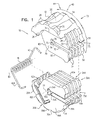
Fig. 1 is a schematic exploded view of a catheter device, according to an embodiment of the present invention; -
Fig. 2 is a schematic view of the assembled device in an open state, according to an embodiment of the present invention; -
Fig. 3 is another schematic view of the assembled device in the open state, according to an embodiment of the present invention; -
Fig. 4 is a schematic view of the catheter device in a closed state, according to an embodiment of the present invention; -
Fig. 5 is another schematic view of the catheter device in the closed state, according to an embodiment of the present invention; and -
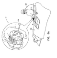
Figs. 6A and6B are schematic views of the grip in a closed state; according to embodiments of the present invention. - It is advantageous that a catheter that is inserted into a patient during a medical procedure has a diameter that is as small as possible, to reduce trauma to the patient. However, the small diameter of the catheter, together with its length which is typically of the order of 1 meter, determines that the catheter is inherently flexible. While the flexibility may be an advantage, allowing, for example, the catheter to be inserted into a non-linear lumen, the small diameter of the catheter and its relatively long length typically makes the catheter difficult to manipulate.
- Embodiments of the present invention facilitate the manipulation by providing a physician manipulating the catheter with a device that grips the catheter and which has a large mechanical advantage. A disclosed embodiment uses a pair of jaws, typically multi-ridged interleaved jaws, connected by a resilient joint such as a spring, as a catheter grip. Manual compression of the jaws aligns passages in the jaws so that a catheter can be inserted into a central region of the jaws. Releasing the manual compression, so that the spring of the grip returns to a "rest" condition, puts the grip into a relaxed state, herein also termed a grip uncompressed state, which is configured to automatically grasp the catheter.
- An external diameter of the grip is considerably larger than the small diameter of the catheter, providing a mechanical advantage to the physician corresponding to the ratio of the two diameters. Consequently, in the grip relaxed-state virtually no effort is required by a physician in holding the catheter, and the relaxed-state grip may be easily grasped by the physician, enabling the physician to rotate and/or translate the catheter with very little effort.
- In its relaxed-state the grip may be inserted into a free-standing cradle, relieving the physician of the need to hold the grip or the catheter. In its relaxed state the multiple ridges of the interleaved elements may be configured to align, forming ridges and intermediary indentations across the grip. A spring-loaded stopper may be attached to the cradle, so that, in a pawl-like manner, while the grip is in the cradle the stopper is able to engage with the aligned ridges and indentations of the grip. Alternatively, other indentations may be configured in the grip, and the stopper may be configured to engage with these indentations.
- Typically, the free-standing cradle is attached to an adjustable arm, usually an articulated arm, which enables the cradle to be located in any orientation and/or location that is suitable for accepting the grip. The combination of the adjustable arm together with spring-loaded stopper, enables adjustments to made to orientation and location of the grip, and thus to the orientation and location of the catheter. Once the adjustments have been made, the stopper may engage with the indentations referred to above in order to lock the grip and the catheter in place.
-
Fig. 1 is a schematic exploded view of acatheter device 10,Fig. 2 is a schematic view of the assembled device in an open state, andFig. 3 is another schematic view of the assembled device in the open state, according to an embodiment of the present invention.Device 10 is configured to grip a catheter, and is also herein termedgrip 10.Grip 10 is comprised of three entities: a pair ofridged jaws resilient joint 16, herein assumed to comprise a spring and also referred to asspring 16.Jaws ridged jaws jaws grip 10 has an approximately circular cross-section. - For simplicity, the following description of the ridged jaws is written for jaw 12, and except where otherwise noted the same description applies for
jaw 14. To differentiate corresponding parts of the two jaws the letter A is added to the identifying numeral ofjaw 14. Thus,jaw 12 comprises a holdingportion 20, andjaw 14 comprises a holdingportion 20A. Holdingportions exterior sides Portions -
Exterior side 20 is bounded by a generallyarcuate section 24, andridges 28 andindentations 30 substantially traverse the complete width of the side. Apart fromarcuate section 24,exterior side 20 is also bounded by a pair of generallylinear elements groove 40, shaped to accept a correspondingportion 42 ofspring 16, is formed in anouter surface 44 ofside 20. -
Jaw 12 also comprises a leafedportion 50 which is attached to holdingportion 20.Leafed portion 50 comprises a plurality of generallysimilar leaves 54, assumed herein by way of example to comprise fiveleaves 54, four of which have similar widths, and a fifth, outer, leaf being thicker than the other leaves. Where the leaves are not attached to holdingportion 20, they are each bounded by a generallyarcuate section 56, the arc ofsection 56 continuing the arc ofarcuate section 24. The leaves are also bounded by two generallylinear sections Ridges 28 andindentations 30 are formed inarcuate section 36. In addition, apassage 70 is formed in each of the leaves, the passage having a width somewhat greater than the diameter of a catheter to be held bygrip 10.Passage 70 is formed in each of leaves 54 as a generally radial element, each passage extending approximately from the equivalent of acenter 72 of acircle 73 defined by the arcs ofsections exit point 75 of the circle. At its termination atcenter 72,passage 70 is configured as two half-circles circles grip 10. Half-circles 74A have a commoncentral axis 77; half-circles 74 have a commoncentral axis 79.Axes -
Grip 10 is assembled by inserting ridgedjaws leaves spring portions spring 16 respectively mate withgrooves -
Fig. 2 and Fig. 3 schematically illustrategrip 10 after assembly, and whenspring 16 has been compressed. The state of the grip in this case, caused by manual compression of the grip, is termed the compressed grip state. The compressed grip state is typically achieved by graspingexterior sides jaws axis 80 ofspring 16. The rotation rotateslinear elements linear elements linear elements linear elements - In the compressed
grip state passages centers passages Fig. 3 ) corresponding to aligned exit points 75, 75A, in proximity to the circumferential termination ofpassages ridges indentations -
Grip 10 may transfer from its compressed state to an uncompressed state by the grip operator relaxing his/her hold onportions jaws axis 80 in a direction opposite to the rotation direction to achieve the compressed state. -
Figs. 4 and 5 are two schematic views ofgrip 10 in its uncompressed state, according to an embodiment of the present invention. In theuncompressed state passages circles 74 and sets of half-circles 76A, and half-circles circles 74A and half-circles 74, so thataxes like opening 82. If acatheter 90 has been placed withinpassages grip 10 in its compressed state, then the catheter moves to opening 82 along alignedaxes uncompressed state ridges indentations region 78. - By virtue of the external diameter of
grip 10, it is significantly easier for a physician to rotate and/or translatecatheter 90 grasped bygrip 10, as compared to the physician attempting to rotate or translate the catheter by grasping the catheter directly. Typically, an external diameter D (Fig. 5 ) of a curved surface ofgrip 10, corresponding toexterior side 20 ofjaw 12 andexterior side 20A ofjaw 14, is configured to be at least 15 times the diameter of the catheter held by the grip. In some embodiments of the present invention, a number of grips, generally similar togrip 10 but having different external diameters, may be made available to the physician, enabling the physician to select a grip most suitable for manipulating the catheter. In an alternative embodiment, the external diameter ofgrip 10 may be custom-formed according to the requirement of a specific physician. -
Fig. 6A is a schematic drawing ofgrip 10, in its uncompressed state, as it is held by aphysician 100 during a medical procedure, andFig. 6B is a schematic drawing of the grip mounted in a cradle during the procedure, according to embodiments of the present invention. A typical medical procedure wheregrip 10 may be used comprises an ablation procedure performed byphysician 100 on apatient 102, although other medical procedures where the grip could be used will be apparent to those having ordinary skill in the art. During theprocedure physician 100 insertscatheter 90 into the patient, and at any convenient time after an initial insertion the physician may grasp the catheter withgrip 10. The grasping of the catheter bygrip 10 is performed by inserting the catheter intopassages - Using
grip 10 in its uncompressed state the physician manipulates the catheter into a desired position, as is illustrated inFig. 6A . Once in position, the grip, with the grasped catheter may be placed in acradle 110 as is illustrated inFig. 6B .Cradle 110 comprises a generallyU-shaped element 112 having an internal diameter approximately equal to the external diameter ofgrip 10. Twoplane elements element 112. -
Plane elements U-shaped openings U-shaped openings catheter 90 to freely move in the openings, so that whengrip 10, with its graspedcatheter 90, is placed in the cradle, there is very little force exerted on the catheter by the cradle. -
Cradle 110 comprises a spring-loadedstopper 130, which typically has ahead 132 having a shape matching the shape ofindentations Element 112 comprises anopening allowing head 132 to contact the periphery, i.e., sides 20, 20A, ofgrip jaws Stopper 130 also has abase 136 and the stopper may typically be operated by the operator pressing onbase 136. A stopper-disengaged state occurs when the operator presses onbase 136, so thathead 132 does not engage withridges indentations base 136, so thathead 122contacts ridges indentations indentations grip 10, andcatheter 90, in place. Thus,stopper 130 andgrip 10 act as a pawl and ratchet combination. - By way of example the description above of
stopper 130 assumes that the stopper is mounted onU-shaped element 112 ofcradle 110. However, it will be understood thatstopper 130 may be mounted on any other convenient element of the cradle such as onplane elements U-shaped element 112, those having ordinary skill in the art will be able to adapt the above description for the operation of the stopper, mutatis mutandis, to accommodate changes that may be required for the operation. Such changes may include, but are not limited to, incorporating ridges and/or indentations, engadgeable by the stopper, inouter leaves 54 and/or 54A if the stopper is mounted onelements -
Cradle 100 may typically be mounted on anadjustable arm 140 which may be fixed at its base, or which may have its base adjustable, such as by mounting the base on a rail. The cradle mounting is configured so that the cradle may be conveniently fixedly positioned in any location selected by the physician. Once the grip is fixed in position, the physician has his/her hands free for other tasks. - It will be appreciated that the embodiments described above are cited by way of example, and that the present invention is not limited to what has been particularly shown and described hereinabove. Rather, the scope of the present invention includes both combinations and subcombinations of the various features described hereinabove, as well as variations and modifications thereof which would occur to persons skilled in the art upon reading the foregoing description and which are not disclosed in the prior art.
Claims (12)
- A device for gripping a catheter, the device comprising:a first jaw having a first grip surface on a first exterior side of the device and containing a first radial passage extending through the first jaw between a first central axis of the first jaw and a first exit point on an outer surface of the device;a second jaw having a second grip surface on a second exterior side of the device, opposite to the first exterior side, and containing a second radial passage extending through the second jaw between a second central axis of the second jaw and a second exit point on the outer surface of the device; anda resilient joint connecting the first and second jaws so that manual compression of the first exterior side toward the second exterior side causes a relative rotation between the first and second jaws that mutually aligns the first and second radial passages and the first and second exit points, such that the catheter can be inserted through the first and second radial passages to the first and second central axes, and so that releasing the manual compression causes the first and second jaws to rotate so that the first and second radial passages are no longer mutually aligned while the first and second central axes are in mutual alignment, and so that the catheter passes through and is gripped by the device along the mutually aligned first and second central axes.
- A method for gripping a catheter, comprising:providing a first jaw having a first grip surface on a first exterior side of the first jaw and containing a first radial passage extending through the first jaw between a first central axis of the first jaw and a first exit point on an outer surface of the first jaw;providing a second jaw having a second grip surface on a second exterior side of the second jaw, opposite to the first exterior side, and containing a second radial passage extending through the second jaw between a second central axis of the second jaw and a second exit point on an outer surface of the second jaw; andconnecting the first and second jaws with a resilient joint so that manual compression of the first exterior side toward the second exterior side causes a relative rotation between the first and second jaws that mutually aligns the first and second radial passages and the first and second exit points, such that the catheter can be inserted through the first and second radial passages to the first and second central axes, and so that releasing the manual compression causes the first and second jaws to rotate so that the first and second radial passages are no longer mutually aligned while the first and second central axes are in mutual alignment, and so that the catheter passes through and is gripped by the first and second jaws along the mutually aligned first and second central axes.
- The device according to claim 1 or the method according to claim 2, wherein the first jaw comprises a first plurality of first jaw leaves, and the second jaw comprises a second plurality of second jaw leaves which interleave with the first jaw leaves.
- The device according to claim 1 or the method according to claim 2, wherein the first and second jaws have identical geometric forms.
- The device according to claim 1 or the method according to claim 2, wherein the first grip surface comprises a first set of ridges and indentations, and the second grip surface comprises a second set of ridges and indentations.
- The device or method according to claim 5, wherein the first set and the second set align in a region in proximity to the first exit point and the second exit point on release of the manual compression.
- The device according to claim 5, wherein the first jaw, the second jaw, and the resilient joint connecting the jaws form a catheter grip, the device further comprising a cradle which is configured to receive the catheter grip.
- The device according to claim 7, wherein the cradle comprises a pawl which is configured to engage with the indentations so as to lock the catheter grip in place in the cradle.
- The method according to claim 5, wherein the first jaw, the second jaw, and the resilient joint connecting the jaws form a catheter grip, the method further comprising providing a cradle which is configured to receive the catheter grip.
- The method according to claim 9, wherein the cradle comprises a pawl which is configured to engage with the indentations so as to lock the catheter grip in place in the cradle.
- The device according to claim 1 or the method according to claim 2, wherein release of the manual compression causes the device to form an opening having an axis of symmetry corresponding to the mutually aligned first and second central axes, and wherein the opening has a diameter configured to grip the catheter.
- The device according to claim 1 or the method according to claim 2, wherein the catheter has a catheter diameter, and wherein release of the manual compression causes the first and second exterior sides to form a curved surface having a diameter at least 15 times greater than the catheter diameter.
Applications Claiming Priority (2)
| Application Number | Priority Date | Filing Date | Title |
|---|---|---|---|
| US201461935932P | 2014-02-05 | 2014-02-05 | |
| US14/597,382 US10596349B2 (en) | 2014-02-05 | 2015-01-15 | Catheter clips |
Publications (1)
| Publication Number | Publication Date |
|---|---|
| EP2910274A1 true EP2910274A1 (en) | 2015-08-26 |
Family
ID=52462166
Family Applications (1)
| Application Number | Title | Priority Date | Filing Date |
|---|---|---|---|
| EP15153765.1A Withdrawn EP2910274A1 (en) | 2014-02-05 | 2015-02-04 | Catheter clips |
Country Status (7)
| Country | Link |
|---|---|
| US (1) | US10596349B2 (en) |
| EP (1) | EP2910274A1 (en) |
| JP (1) | JP6474628B2 (en) |
| CN (1) | CN104815381B (en) |
| AU (1) | AU2015200538B2 (en) |
| CA (1) | CA2879042A1 (en) |
| IL (1) | IL236886B (en) |
Families Citing this family (9)
| Publication number | Priority date | Publication date | Assignee | Title |
|---|---|---|---|---|
| CN105708505B (en) * | 2016-03-29 | 2018-10-02 | 中国人民解放军第二军医大学 | Disposable quickly adjustment type twisting controller |
| EP3735199A4 (en) * | 2018-01-04 | 2021-10-13 | Covidien LP | SYSTEMS AND ARRANGEMENTS FOR ATTACHING A SURGICAL ACCESSORY TO ROBOTIC SURGICAL SYSTEMS AND PROVIDING ACCESS THROUGH |
| AU2019295617B2 (en) | 2018-06-25 | 2025-02-06 | Novonate, Inc. | Systems and methods for securing catheters |
| USD907768S1 (en) | 2019-06-21 | 2021-01-12 | Novonate, Inc. | Catheter securing device |
| PT4221799T (en) * | 2020-09-29 | 2026-03-17 | Hopitaux Univ De Strasbourg Hus | DEVICE FOR ANCHORING A MEDICAL DEVICE INTRODUCER INTO THE HUMAN BODY |
| CN113599670B (en) * | 2021-10-08 | 2021-12-03 | 江苏康亦徳医疗器械有限公司 | Portable medical pipe clamp |
| CN114246686B (en) * | 2021-12-24 | 2025-08-12 | 天津科技大学 | Interventional operation manipulator for compensating tail end micro-motion error |
| CN116350396B (en) * | 2021-12-28 | 2025-10-17 | 杭州启明医疗器械股份有限公司 | Compression device of interventional instrument and operation method |
| CN117918909B (en) * | 2024-03-22 | 2024-06-04 | 湘潭市中心医院 | Hitching type suction device for surgical operation |
Citations (5)
| Publication number | Priority date | Publication date | Assignee | Title |
|---|---|---|---|---|
| US5405110A (en) * | 1993-10-08 | 1995-04-11 | Wisconsin Alumni Research Foundation | Catheter holding apparatus |
| US20050096688A1 (en) | 2003-10-30 | 2005-05-05 | Robert Slazas | Gripper for catheter shaft |
| US20050277909A1 (en) * | 2004-06-14 | 2005-12-15 | Mcdaniel Benjamin D | Catheter grip |
| US20100145280A1 (en) * | 2008-12-05 | 2010-06-10 | Daniels Jr Richard Dean | Catheter clip for securing a catheter hub to a patient |
| US20130096505A1 (en) * | 2011-10-14 | 2013-04-18 | William F. Urmey | Catheter positioning system |
Family Cites Families (8)
| Publication number | Priority date | Publication date | Assignee | Title |
|---|---|---|---|---|
| US4986815A (en) | 1989-12-11 | 1991-01-22 | Hollister Incorporated | Nasogastric tube holding device |
| JP3009426U (en) | 1994-09-22 | 1995-04-04 | エフシー総研株式会社 | Grip for towing line |
| US6305053B1 (en) * | 2000-02-01 | 2001-10-23 | John A. Galbreath | Cord lock |
| US7077841B2 (en) | 2001-03-26 | 2006-07-18 | Curon Medical, Inc. | Systems and methods employing a guidewire for positioning and stabilizing external instruments deployed within the body |
| JP4648801B2 (en) * | 2005-08-31 | 2011-03-09 | Ykk株式会社 | Tie fastener |
| US20100100103A1 (en) * | 2008-09-15 | 2010-04-22 | Elcam Agricultural Cooperative Association Ltd. | Torque device with side attachment |
| TWM386322U (en) * | 2009-12-10 | 2010-08-11 | Jin-Yang Xu | Functional agent releasing device used in toilet |
| WO2012064347A1 (en) | 2010-11-09 | 2012-05-18 | Hakky Said I | Urinary catheter stabilizer and method of use |
-
2015
- 2015-01-15 US US14/597,382 patent/US10596349B2/en not_active Expired - Fee Related
- 2015-01-21 CA CA2879042A patent/CA2879042A1/en not_active Abandoned
- 2015-01-22 IL IL236886A patent/IL236886B/en not_active IP Right Cessation
- 2015-02-04 JP JP2015019971A patent/JP6474628B2/en not_active Expired - Fee Related
- 2015-02-04 EP EP15153765.1A patent/EP2910274A1/en not_active Withdrawn
- 2015-02-04 CN CN201510058911.4A patent/CN104815381B/en not_active Expired - Fee Related
- 2015-02-05 AU AU2015200538A patent/AU2015200538B2/en not_active Ceased
Patent Citations (5)
| Publication number | Priority date | Publication date | Assignee | Title |
|---|---|---|---|---|
| US5405110A (en) * | 1993-10-08 | 1995-04-11 | Wisconsin Alumni Research Foundation | Catheter holding apparatus |
| US20050096688A1 (en) | 2003-10-30 | 2005-05-05 | Robert Slazas | Gripper for catheter shaft |
| US20050277909A1 (en) * | 2004-06-14 | 2005-12-15 | Mcdaniel Benjamin D | Catheter grip |
| US20100145280A1 (en) * | 2008-12-05 | 2010-06-10 | Daniels Jr Richard Dean | Catheter clip for securing a catheter hub to a patient |
| US20130096505A1 (en) * | 2011-10-14 | 2013-04-18 | William F. Urmey | Catheter positioning system |
Also Published As
| Publication number | Publication date |
|---|---|
| JP2015163191A (en) | 2015-09-10 |
| AU2015200538B2 (en) | 2019-01-17 |
| CN104815381A (en) | 2015-08-05 |
| US10596349B2 (en) | 2020-03-24 |
| IL236886B (en) | 2020-06-30 |
| JP6474628B2 (en) | 2019-02-27 |
| CN104815381B (en) | 2019-12-17 |
| US20150217087A1 (en) | 2015-08-06 |
| AU2015200538A1 (en) | 2015-08-20 |
| CA2879042A1 (en) | 2015-08-05 |
Similar Documents
| Publication | Publication Date | Title |
|---|---|---|
| US10596349B2 (en) | Catheter clips | |
| US7234677B2 (en) | Pinch clamp | |
| RU2761389C1 (en) | Surgical device | |
| AU696599B2 (en) | Endoscopic multiple sample bioptome with enhanced biting action | |
| US7186224B2 (en) | Side attaching guidewire torque device | |
| CN103917171B (en) | A surgical suture apparatus | |
| US20050070820A1 (en) | Side loading wire torquing device | |
| AU2015336119B2 (en) | Torque device and securement mechanism | |
| US12186504B2 (en) | Guidewire torque device and method of use | |
| US20130304041A1 (en) | Handling device for a medical instrument | |
| EP1839604A1 (en) | Device for performing examinations and surgical operations on the uterus | |
| EP2967546B1 (en) | Needle driver | |
| US8287654B2 (en) | Apparatus for clearing tubing and related method | |
| US20190070391A1 (en) | Catheter and guidewire advancement device | |
| CN105078542A (en) | Operating forceps with negative pressure suction function | |
| JP6233146B2 (en) | Device for releasing holding of body tissue holding member | |
| CA2551477A1 (en) | Side loading needle depth stop | |
| US11090462B2 (en) | Advancement or retraction device | |
| CN220632243U (en) | Orthodontic pliers | |
| CN115568627B (en) | Clamp type cigarette taking device | |
| CN110559064A (en) | Alimentary canal metal clip unblock puller | |
| EP3009087A1 (en) | Detachable articulating endoscopic tool cartridge | |
| JP6776581B2 (en) | Clip removal device | |
| US20060025779A1 (en) | Tube insertion device and method therefor |
Legal Events
| Date | Code | Title | Description |
|---|---|---|---|
| PUAI | Public reference made under article 153(3) epc to a published international application that has entered the european phase |
Free format text: ORIGINAL CODE: 0009012 |
|
| AK | Designated contracting states |
Kind code of ref document: A1 Designated state(s): AL AT BE BG CH CY CZ DE DK EE ES FI FR GB GR HR HU IE IS IT LI LT LU LV MC MK MT NL NO PL PT RO RS SE SI SK SM TR |
|
| AX | Request for extension of the european patent |
Extension state: BA ME |
|
| 17P | Request for examination filed |
Effective date: 20160225 |
|
| RBV | Designated contracting states (corrected) |
Designated state(s): AL AT BE BG CH CY CZ DE DK EE ES FI FR GB GR HR HU IE IS IT LI LT LU LV MC MK MT NL NO PL PT RO RS SE SI SK SM TR |
|
| GRAP | Despatch of communication of intention to grant a patent |
Free format text: ORIGINAL CODE: EPIDOSNIGR1 |
|
| STAA | Information on the status of an ep patent application or granted ep patent |
Free format text: STATUS: GRANT OF PATENT IS INTENDED |
|
| RIC1 | Information provided on ipc code assigned before grant |
Ipc: A61B 90/50 20160101ALI20200423BHEP Ipc: A61M 25/02 20060101AFI20200423BHEP Ipc: A61B 17/00 20060101ALN20200423BHEP |
|
| INTG | Intention to grant announced |
Effective date: 20200514 |
|
| STAA | Information on the status of an ep patent application or granted ep patent |
Free format text: STATUS: THE APPLICATION IS DEEMED TO BE WITHDRAWN |
|
| 18D | Application deemed to be withdrawn |
Effective date: 20200925 |