EP2909446B1 - Reversible blade damper - Google Patents
Reversible blade damper Download PDFInfo
- Publication number
- EP2909446B1 EP2909446B1 EP13870280.8A EP13870280A EP2909446B1 EP 2909446 B1 EP2909446 B1 EP 2909446B1 EP 13870280 A EP13870280 A EP 13870280A EP 2909446 B1 EP2909446 B1 EP 2909446B1
- Authority
- EP
- European Patent Office
- Prior art keywords
- damper
- lug
- lateral side
- pair
- blades
- Prior art date
- Legal status (The legal status is an assumption and is not a legal conclusion. Google has not performed a legal analysis and makes no representation as to the accuracy of the status listed.)
- Active
Links
Images




Classifications
-
- F—MECHANICAL ENGINEERING; LIGHTING; HEATING; WEAPONS; BLASTING
- F01—MACHINES OR ENGINES IN GENERAL; ENGINE PLANTS IN GENERAL; STEAM ENGINES
- F01D—NON-POSITIVE DISPLACEMENT MACHINES OR ENGINES, e.g. STEAM TURBINES
- F01D5/00—Blades; Blade-carrying members; Heating, heat-insulating, cooling or antivibration means on the blades or the members
- F01D5/12—Blades
- F01D5/22—Blade-to-blade connections, e.g. for damping vibrations
-
- F—MECHANICAL ENGINEERING; LIGHTING; HEATING; WEAPONS; BLASTING
- F01—MACHINES OR ENGINES IN GENERAL; ENGINE PLANTS IN GENERAL; STEAM ENGINES
- F01D—NON-POSITIVE DISPLACEMENT MACHINES OR ENGINES, e.g. STEAM TURBINES
- F01D11/00—Preventing or minimising internal leakage of working-fluid, e.g. between stages
- F01D11/005—Sealing means between non relatively rotating elements
-
- F—MECHANICAL ENGINEERING; LIGHTING; HEATING; WEAPONS; BLASTING
- F01—MACHINES OR ENGINES IN GENERAL; ENGINE PLANTS IN GENERAL; STEAM ENGINES
- F01D—NON-POSITIVE DISPLACEMENT MACHINES OR ENGINES, e.g. STEAM TURBINES
- F01D11/00—Preventing or minimising internal leakage of working-fluid, e.g. between stages
- F01D11/005—Sealing means between non relatively rotating elements
- F01D11/006—Sealing the gap between rotor blades or blades and rotor
-
- F—MECHANICAL ENGINEERING; LIGHTING; HEATING; WEAPONS; BLASTING
- F01—MACHINES OR ENGINES IN GENERAL; ENGINE PLANTS IN GENERAL; STEAM ENGINES
- F01D—NON-POSITIVE DISPLACEMENT MACHINES OR ENGINES, e.g. STEAM TURBINES
- F01D11/00—Preventing or minimising internal leakage of working-fluid, e.g. between stages
- F01D11/005—Sealing means between non relatively rotating elements
- F01D11/006—Sealing the gap between rotor blades or blades and rotor
- F01D11/008—Sealing the gap between rotor blades or blades and rotor by spacer elements between the blades, e.g. independent interblade platforms
-
- F—MECHANICAL ENGINEERING; LIGHTING; HEATING; WEAPONS; BLASTING
- F01—MACHINES OR ENGINES IN GENERAL; ENGINE PLANTS IN GENERAL; STEAM ENGINES
- F01D—NON-POSITIVE DISPLACEMENT MACHINES OR ENGINES, e.g. STEAM TURBINES
- F01D5/00—Blades; Blade-carrying members; Heating, heat-insulating, cooling or antivibration means on the blades or the members
- F01D5/12—Blades
- F01D5/26—Antivibration means not restricted to blade form or construction or to blade-to-blade connections or to the use of particular materials
-
- F—MECHANICAL ENGINEERING; LIGHTING; HEATING; WEAPONS; BLASTING
- F05—INDEXING SCHEMES RELATING TO ENGINES OR PUMPS IN VARIOUS SUBCLASSES OF CLASSES F01-F04
- F05D—INDEXING SCHEME FOR ASPECTS RELATING TO NON-POSITIVE-DISPLACEMENT MACHINES OR ENGINES, GAS-TURBINES OR JET-PROPULSION PLANTS
- F05D2260/00—Function
- F05D2260/30—Retaining components in desired mutual position
- F05D2260/36—Retaining components in desired mutual position by a form fit connection, e.g. by interlocking
Definitions
- This application relates generally to a turbine blade platform seal and damper assembly and specifically to a reversible blade damper within the assembly.
- Conventional gas turbine engines include a turbine assembly that has a plurality of turbine blades attached about a circumference of a turbine rotor. Each of the turbine blades is spaced a distance apart from adjacent turbine blades to accommodate movement and expansion during operation.
- the blades typically include an attachment that attaches to the rotor, a platform that extends between pressure and suction sides, and an airfoil that extends radially outwardly from the platform. There is a gap between adjacent platforms.
- a blade platform seal is utilized to span the gap, as relatively cool air for cooling the blade is radially inward of the platform, and the hot products of combustion are radially outward of the platform.
- the blade platform seal has typically also been associated with a damper which dissipates potential vibrations. The damper fits within pockets in the sides of the two adjacent blades.
- the damper has four lugs extending in an axial direction away from a main damper body. Three of the lugs have extended generally perpendicular to the sides of the damper, and a forth lug has a circumferentially outwardly extending foot. The foot is received within a pocket in one side of one of the blades, and assures that the damper will not come out of its desired location between the two adjacent blades. In addition, a shoulder provides a radial reaction surface with a post on the blade.
- the dampers may sometimes have been assembled relative to a seal 180° out of their proper orientation.
- the circumferentially outwardly extending foot points toward the opposed blade, which has no need for the foot.
- the blade pocket which should receive the foot does not, and thus the damper has not always been adequately secured.
- the shoulder will be out of position relative to the post on the blade.
- FIG 1A shows a prior art damper 100.
- the seal 70 (see Figures 1C/D ) will be secured between the shoulders 102.
- a first lug 104 extends generally parallel to the sides 12 of the shoulders 102, as do lugs 110 and 112. These lugs all fit within pocket structure on the adjacent blades, as can be appreciated from the following disclosure.
- one lug 106 has a circumferentially outwardly extending foot 108.
- Figure 1B shows the bottom side of the damper 100.
- Axial Reaction Surface 114 also extends in a direction away from the seal, which is secured on the opposed side.
- Figure 1C shows an assembled damper 100 and seal 70 with the prior art damper.
- the lug 106 has its foot 108 extending in a direction such that the foot 108 will be properly received in a pocket in a blade.
- the shoulder 115 will be received above a post.
- US 5478207 discloses a prior art damper-seal assembly.
- US 2006/0056974 discloses a prior art damper seal as set forth in the preamble of claim 1.
- US 2009/0004013 discloses a prior art damper seal assembly.
- EP 1 867 836 discloses a damping system for a turbine bucket.
- the damper body also has a pair of radial reaction shoulders on the first lateral side, and a pair of radial reaction shoulders on the sec ond lateral side.
- the invention also provides a gas turbine engine blade as set forth in claim 3.
- the invention also provides a turbine assembly as set forth in claim 4.
- the damper body can be installed on a seal in either of two orientations. There will still be a foot received in a pocket on one of the first and second blades.
- the damper body also has a pair of radial reaction shoulders on the first lateral side, and a pair of radial reaction shoulders on the second lateral side.
- both of the first and second blades have a pocket adjacent the leading edge, and a post spaced toward the trailing edge from the leading edge on both of the suction and pressure sides.
- One of the first and second feet is received in the pocket of one of the first and second blades, with the other of the first and second feet being on an opposed axial side of one of the posts relative to one of the feet.
- one of the radial reaction shoulders on each of the first and second lateral sides is positioned radially outwardly of one of the posts on each of the first and second blades, and the other of the radial reaction shoulders on each of the first and second lateral sides is spaced axially from the post.
- a gas turbine engine 10 includes a fan section 12, a compressor section 14, a combustor section 16, and a turbine section 18. Air entering into the fan section 12 is initially compressed and fed to the compressor section 14. In the compressor section 14, the incoming air from the fan section 12 is further compressed and communicated to the combustor section 16. In the combustor section 16, the compressed air is mixed with gas and ignited to generate a hot exhaust stream 28. The hot exhaust stream 28 is expanded through the turbine section 18 to drive the fan section 12 and the compressor section 14.
- the gas turbine engine 10 includes an augmenter section 20 where additional fuel can be mixed with the exhaust gasses 28 and ignited to generate additional thrust. The exhaust gasses 28 flow from the turbine section 18 and the augmenter section 20 through an exhaust liner assembly 22.
- a turbine section 18 includes a plurality of adjacent turbine blades 60.
- Each of the turbine blades 60 includes an attachment 15 that is fit into a radial slot of a turbine rotor (not shown).
- a platform 61 is positioned radially inwardly of an airfoil 62.
- the airfoil 62 extends from a leading edge 64 to a trailing edge 65.
- the platform has a suction side 68 and a pressure side 66. There is a gap 17 between the pressure side 66 of one blade 60, and the suction side 68 of the adjacent blade 60.
- the seal 70 and damper 72 are received on blade 60, just beneath the platform 61.
- a post 74 that provides a reaction surface for structure on the damper 72.
- a pocket 76 beneath the leading edge 64 of the airfoil, which will also receive structure from the damper 72, to secure the damper 72 in the pocket.
- the post 74 is positioned towards the trailing edge 65 from the pocket 76.
- the damper 72 will be received adjacent to this structure.
- the damper has a lug 151 having a circumferentially outwardly extending foot 152 extending away from the pocket 76. This will be explained in greater detail below.
- an axial reaction surface 172 is positioned axially adjacent to post 74.
- a shoulder 170C sits atop the post 74, or radially outwardly, to provide a radial reaction surface.
- a shoulder 170D is spaced from post 74, and provides no function in this position.
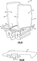
- FIG 5A shows the pressure side 66 of the blade 60.
- Another pocket 176 is positioned toward the leading edge 64 and another post 174 is positioned in a direction toward the trailing edge 65 from the pocket 176.
- the damper 72 and seal 70 are shown mounted to blade 60.
- the foot 152 extends circumferentially away from the suction wall as shown in Figure 4B , and extends into the pocket 176 to assist in securing the damper 72.
- lug 158 is shown with a circumferentially outwardly extending foot 160 extending away from this pressure side 66. As can be appreciated from this Figure, the foot 160 would not contact any structure on the blade 60. The purpose of this feature will be described below.
- an axial reaction surface 172 is positioned axially adjacent to post 174, and the shoulder 170B sits atop the post 174, or radially outwardly, to provide a radial reaction surface.
- the shoulder 170A performs no function in this position.
- Figure 6A shows the previously identified improved damper 72. Again, there are shoulders 161 to secure the seal 70 in a channel 163 underneath shoulders 161. Lugs 154 and 156 extend generally parallel to the sides 153 defined by the shoulders 161. Stated another way, the lugs 154 and 156 have axially extending sides 153A and 153B, respectively, which extend along an axis of the engine. Ends 301A and B of the lugs 154 and 156, respectively, do not extend circumferentially outwardly of those sides 153A and 153B.
- a lug 151 has a circumferentially outwardly extending foot 152 which extends circumferentially, or laterally, beyond the side 153C of the lug 151.
- a lug 158 having a circumferentially extending foot 160 which also extends circumferentially, or laterally, beyond the side 153D.
- the damper 72 has shoulders 170A and 170D on one side of the axial reaction surface 172, and shoulders 170B and 170C on the other.
- the damper could be described as having a damper body 72 extending along an axial dimension from an axial first end 301A to an opposing axial second end 301B, and between a first lateral side 302, and an opposing second lateral side 303.
- the damper body 72 has four lugs, including a first pair of lugs 151, 154 disposed at the first axial end and a second pair lugs 156, 158 disposed at the second axial end.
- a first lug in each lug pair is on the first lateral side of the damper and a second lug in each lug pair is on the second lateral side of the damper.
- the first lug 154 extends to an axially outermost point, which is not laterally beyond a lateral side wall 153A of the first lug 154.
- the second lug 151 has an axially outermost foot 152, which extends laterally beyond a lateral wall 153C of the second lug 151.
- the second lug pair has a second lug 156 with an axial outermost point which does not extend laterally beyond a lateral side wall 153B.
- the first lug 158 has an axial outermost point with a foot 160 extending laterally beyond a lateral wall 153D.
- the foot 152 on the first axial end 301A of the damper is on the second lateral side 303, and the foot 160 on the second axial end 301B is on the first lateral side 302.
- the damper is generally a mirror image such that it can be installed on a seal in either of two orientations, and there will still be a foot 152/160 facing an intended pocket on a gas turbine engine blade which is to receive said damper.
- the damper 72 is mirrored such that even if installed 180° from a desired position, there will still be a circumferentially outwardly extending foot 152, or 160, in the desired position.
- the unused mirrored foot creates no concern, as it merely sits in empty space.
Landscapes
- Engineering & Computer Science (AREA)
- Mechanical Engineering (AREA)
- General Engineering & Computer Science (AREA)
- Turbine Rotor Nozzle Sealing (AREA)
- Fluid-Damping Devices (AREA)
Description
- This application relates generally to a turbine blade platform seal and damper assembly and specifically to a reversible blade damper within the assembly.
- Conventional gas turbine engines include a turbine assembly that has a plurality of turbine blades attached about a circumference of a turbine rotor. Each of the turbine blades is spaced a distance apart from adjacent turbine blades to accommodate movement and expansion during operation. The blades typically include an attachment that attaches to the rotor, a platform that extends between pressure and suction sides, and an airfoil that extends radially outwardly from the platform. There is a gap between adjacent platforms.
- A blade platform seal is utilized to span the gap, as relatively cool air for cooling the blade is radially inward of the platform, and the hot products of combustion are radially outward of the platform. The blade platform seal has typically also been associated with a damper which dissipates potential vibrations. The damper fits within pockets in the sides of the two adjacent blades.
- The damper has four lugs extending in an axial direction away from a main damper body. Three of the lugs have extended generally perpendicular to the sides of the damper, and a forth lug has a circumferentially outwardly extending foot. The foot is received within a pocket in one side of one of the blades, and assures that the damper will not come out of its desired location between the two adjacent blades. In addition, a shoulder provides a radial reaction surface with a post on the blade.
- In the past, the dampers may sometimes have been assembled relative to a seal 180° out of their proper orientation. When this has occurred, the circumferentially outwardly extending foot points toward the opposed blade, which has no need for the foot. The blade pocket which should receive the foot does not, and thus the damper has not always been adequately secured. In addition, the shoulder will be out of position relative to the post on the blade.
-
Figure 1A shows aprior art damper 100. In theprior art damper 100, there is aseal slot 400 defined between twoshoulders 102. The seal 70 (seeFigures 1C/D ) will be secured between theshoulders 102. Afirst lug 104 extends generally parallel to thesides 12 of theshoulders 102, as dolugs lug 106 has a circumferentially outwardly extendingfoot 108. - There are
shoulders 115 on an opposed end of adamper 100 from thefoot 108. Theshoulders 115 will contact a post on associated blades to provide a radial reaction surface. Anaxial reaction surface 114 will sit adjacent the posts. -
Figure 1B shows the bottom side of thedamper 100. Axial Reaction Surface 114 also extends in a direction away from the seal, which is secured on the opposed side. -
Figure 1C shows an assembleddamper 100 andseal 70 with the prior art damper. As shown, thelug 106 has itsfoot 108 extending in a direction such that thefoot 108 will be properly received in a pocket in a blade. Theshoulder 115 will be received above a post. - However, the prior art damper has sometimes been inadvertently mounted such that it is rotated by 180° from the position shown in
Figure 1C . This position is shown inFigure 1D . Now, the circumferentially extendingfoot 108 points in the opposed direction, and will be spaced axially away from the desired position ofFigure 1C . With this arrangement, thestraight lug 112 is received where thefoot 108 is intended. Thelug 112 will not secure thedamper 100 within the blade pocket. In addition, theshoulder 115 is at an improper location, such that there will not be a radial reaction surface. - This is undesirable.
-
US 5478207 discloses a prior art damper-seal assembly.US 2006/0056974 discloses a prior art damper seal as set forth in the preamble of claim 1.US 2009/0004013 discloses a prior art damper seal assembly. -
EP 1 867 836 discloses a damping system for a turbine bucket. - In accordance with the invention, there is provided a damper for use with a turbine seal, as set forth in claim 1.
- In an exemplary embodiment, the damper body also has a pair of radial reaction shoulders on the first lateral side, and a pair of radial reaction shoulders on the sec ond lateral side.
- The invention also provides a gas turbine engine blade as set forth in claim 3.
- The invention also provides a turbine assembly as set forth in claim 4.
- In an exemplary embodiment of the above assembly, the damper body can be installed on a seal in either of two orientations. There will still be a foot received in a pocket on one of the first and second blades.
- In another exemplary embodiment according to any of the previous embodiments, the damper body also has a pair of radial reaction shoulders on the first lateral side, and a pair of radial reaction shoulders on the second lateral side.
- In another exemplary embodiment according to any of the previous embodiments, both of the first and second blades have a pocket adjacent the leading edge, and a post spaced toward the trailing edge from the leading edge on both of the suction and pressure sides. One of the first and second feet is received in the pocket of one of the first and second blades, with the other of the first and second feet being on an opposed axial side of one of the posts relative to one of the feet.
- In another exemplary embodiment according to any of the previous embodiments, one of the radial reaction shoulders on each of the first and second lateral sides is positioned radially outwardly of one of the posts on each of the first and second blades, and the other of the radial reaction shoulders on each of the first and second lateral sides is spaced axially from the post.
- These and other features of this application will be best understood from the following specification and drawings, the following of which is a brief description.
-
- Figure 1A
- shows a prior art damper.
- Figure 1B
- shows a reverse side of the prior art damper.
- Figure 1C
- shows a properly installed prior art damper.
- Figure 1D
- shows an improperly installed prior art damper.
- Figure 2
- schematically shows an engine.
- Figure 3A
- is a perspective view of adjacent turbine blade assemblies
- Figure 3B
- shows a damper and platform seal assembly.
- Figure 4A
- shows a suction side of a turbine blade.
- Figure 4B
- shows how a damper fits within the
Figure 4A suction side. - Figure 5A
- shows a pressure side of a turbine blade.
- Figure 5B
- shows how a damper fits within the
Figure 5A pressure side. - Figure 6A
- shows a damper.
- Figure 6B
- shows the damper mounted on a seal.
- Referring to
Figure 2 , agas turbine engine 10 includes afan section 12, acompressor section 14, acombustor section 16, and aturbine section 18. Air entering into thefan section 12 is initially compressed and fed to thecompressor section 14. In thecompressor section 14, the incoming air from thefan section 12 is further compressed and communicated to thecombustor section 16. In thecombustor section 16, the compressed air is mixed with gas and ignited to generate ahot exhaust stream 28. Thehot exhaust stream 28 is expanded through theturbine section 18 to drive thefan section 12 and thecompressor section 14. In this example, thegas turbine engine 10 includes anaugmenter section 20 where additional fuel can be mixed with theexhaust gasses 28 and ignited to generate additional thrust. Theexhaust gasses 28 flow from theturbine section 18 and theaugmenter section 20 through anexhaust liner assembly 22. - Referring to
Figure 3A , aturbine section 18 includes a plurality ofadjacent turbine blades 60. Each of theturbine blades 60 includes anattachment 15 that is fit into a radial slot of a turbine rotor (not shown). As shown, aplatform 61 is positioned radially inwardly of anairfoil 62. Theairfoil 62 extends from a leadingedge 64 to a trailingedge 65. The platform has asuction side 68 and apressure side 66. There is agap 17 between thepressure side 66 of oneblade 60, and thesuction side 68 of theadjacent blade 60. - A
seal 70 anddamper 72, as shown inFigure 3B , span thegap 17. - As shown in
Figures 4A and 4B , theseal 70 anddamper 72 are received onblade 60, just beneath theplatform 61. As shown, there is apost 74 that provides a reaction surface for structure on thedamper 72. In addition, there is apocket 76 beneath the leadingedge 64 of the airfoil, which will also receive structure from thedamper 72, to secure thedamper 72 in the pocket. - The
post 74 is positioned towards the trailingedge 65 from thepocket 76. As shown inFigure 4B , thedamper 72 will be received adjacent to this structure. As can be appreciated in this figure, the damper has alug 151 having a circumferentially outwardly extendingfoot 152 extending away from thepocket 76. This will be explained in greater detail below. - As can be seen, an
axial reaction surface 172 is positioned axially adjacent to post 74. Ashoulder 170C sits atop thepost 74, or radially outwardly, to provide a radial reaction surface. Ashoulder 170D is spaced frompost 74, and provides no function in this position. -
Figure 5A shows thepressure side 66 of theblade 60. Anotherpocket 176 is positioned toward the leadingedge 64 and anotherpost 174 is positioned in a direction toward the trailingedge 65 from thepocket 176. InFigure 5B , thedamper 72 andseal 70 are shown mounted toblade 60. Thefoot 152 extends circumferentially away from the suction wall as shown inFigure 4B , and extends into thepocket 176 to assist in securing thedamper 72. - In
Figure 5B lug 158 is shown with a circumferentially outwardly extendingfoot 160 extending away from thispressure side 66. As can be appreciated from this Figure, thefoot 160 would not contact any structure on theblade 60. The purpose of this feature will be described below. - As can be seen, an
axial reaction surface 172 is positioned axially adjacent to post 174, and theshoulder 170B sits atop thepost 174, or radially outwardly, to provide a radial reaction surface. Theshoulder 170A performs no function in this position. -
Figure 6A shows the previously identifiedimproved damper 72. Again, there areshoulders 161 to secure theseal 70 in achannel 163 underneath shoulders 161.Lugs sides 153 defined by theshoulders 161. Stated another way, thelugs sides Ends 301A and B of thelugs sides - As can be appreciated, a
lug 151 has a circumferentially outwardly extendingfoot 152 which extends circumferentially, or laterally, beyond theside 153C of thelug 151. Indamper 72, there is anopposed lug 158 having acircumferentially extending foot 160 which also extends circumferentially, or laterally, beyond theside 153D. - As can also be seen, the
damper 72 hasshoulders axial reaction surface 172, and shoulders 170B and 170C on the other. - The damper could be described as having a
damper body 72 extending along an axial dimension from an axialfirst end 301A to an opposing axialsecond end 301B, and between a firstlateral side 302, and an opposing secondlateral side 303. Thedamper body 72 has four lugs, including a first pair oflugs first lug 154 extends to an axially outermost point, which is not laterally beyond alateral side wall 153A of thefirst lug 154. Thesecond lug 151 has an axiallyoutermost foot 152, which extends laterally beyond alateral wall 153C of thesecond lug 151. - The second lug pair has a
second lug 156 with an axial outermost point which does not extend laterally beyond alateral side wall 153B. Thefirst lug 158 has an axial outermost point with afoot 160 extending laterally beyond alateral wall 153D. Thefoot 152 on the firstaxial end 301A of the damper is on the secondlateral side 303, and thefoot 160 on the secondaxial end 301B is on the firstlateral side 302. - The damper is generally a mirror image such that it can be installed on a seal in either of two orientations, and there will still be a
foot 152/160 facing an intended pocket on a gas turbine engine blade which is to receive said damper. In essence, thedamper 72 is mirrored such that even if installed 180° from a desired position, there will still be a circumferentially outwardly extendingfoot - Returning to
Figure 4B andFigure 5B , one can see there will also beshoulders posts other shoulders - Although an embodiment of this invention has been disclosed, a worker of ordinary skill in this art would recognize that certain modifications would come within the scope of this invention. For that reason, the following claims should be studied to determine the true scope and content of this invention.
Claims (8)
- A damper for use with a turbine seal comprising:a damper body (72) extending along an axial dimension, the damper body (72) having an axial first end (301A), an opposing axial second end (301B), a first lateral side (302), and an opposing second lateral side (303);wherein the damper body (72) further comprises four lugs (151, 154, 156, 158), including a first pair of lugs (151, 154) disposed at the first axial end (301A) and a second pair of lugs (156, 158) disposed at the second axial end (301B), wherein:a first lug (154, 158) in each said lug pair is on the first lateral side (302) of the damper and a second lug (151, 156) in each lug pair is on the second lateral side (303) of the damper;characterized in that in said first lug pair (151, 154), the first lug (154) extends to an axially outermost point, which is not laterally beyond a lateral side wall (153A) of said first lug (154), the second lug (151) has an axially outermost first foot (152) which extends laterally beyond a lateral wall (153C) of said second lug (151); andin said second lug pair (156, 158), the second lug (156) has an axial outermost point which does not extend laterally beyond a lateral side wall (153B) of said second lug (156), the first lug (158) having an axial outermost point with a second foot (160) extending laterally beyond a lateral wall (153D) of said first lug (158), and said first foot (152) on said first axial end (301A) of said damper being on the first lateral side (302), and said second foot (160) on said second axial end (301B) being on the second lateral side (303).
- The damper as set forth in claim 1, wherein said damper body (72) also has a pair of radial reaction shoulders (170A, 170B) on said first lateral side (302), and a pair of radial reaction shoulders (170C, 170D) on said second lateral side (303).
- A gas turbine engine blade (60) comprising:a seal (70); andthe damper as set forth in claims 1 or 2, wherein said damper body (72) can be installed on the seal (70) in either of two orientations, and there will still be a foot (152, 160) facing an intended pocket (76) on the gas turbine engine blade (60) which is to receive said damper (72).
- A turbine assembly comprising:a plurality of circumferentially spaced turbine blades (60), each of said turbine blades (60) having an airfoil (62) extending radially outwardly of a platform (61), with said airfoils (62) defining a leading edge (64) and extending to a trailing edge (65), with said trailing edge (65) being generally spaced axially from said leading edge (64), and there being a suction side (68) and a pressure side (66) for each said platform (61) on each of said blades (60), with a seal (70) and damper assembly positioned circumferentially intermediate a suction side (68) of a first of said blades (60), and a pressure side (66) of a second of said blades (60), with said seal (70) being received within shoulders on a body of said damper;the damper being a damper as set forth in claim 1.
- The turbine assembly as set forth in claim 4, wherein said damper body (72) can be installed on the seal (70) in either of two orientations, and there will still be a foot (152, 160) received in a pocket (76) on one of said first and second blades (60).
- The turbine assembly as set forth in claim 5, wherein said damper body (72) also has a pair of radial reaction shoulders (170A, 170B) on said first lateral side (302), and a pair of radial reaction shoulders (170C, 170D) on said second lateral side (303).
- The turbine assembly as set forth in claim 6, wherein both of said first and second blades (60) having a pocket (76) adjacent the leading edge (64), and a post (74) spaced toward said trailing edge (65) from said leading edge (64) on both of said suction and pressure sides (68, 66), and one of said first and second feet (152, 160) being received in said pocket (76) of one of said first and second blades (60), with the other of said first and second feet (152, 160) being on an opposed axial side of one of said posts (74) relative to said one of said feet (152, 160).
- The turbine assembly as set forth in claim 7, wherein one of said radial reaction shoulders (170A, 170B, 170C, 170D) on each of said first and second lateral sides (302, 303) being positioned radially outwardly of one of said posts (74) on each of said first and second blades (60), and the other of said radial reaction shoulders (170A, 170B, 170C, 170D) on each of said first and second lateral sides (302, 303) being spaced axially from said post (74).
Applications Claiming Priority (2)
| Application Number | Priority Date | Filing Date | Title |
|---|---|---|---|
| US13/657,190 US9151165B2 (en) | 2012-10-22 | 2012-10-22 | Reversible blade damper |
| PCT/US2013/065202 WO2014107212A2 (en) | 2012-10-22 | 2013-10-16 | Reversible blade damper |
Publications (3)
| Publication Number | Publication Date |
|---|---|
| EP2909446A2 EP2909446A2 (en) | 2015-08-26 |
| EP2909446A4 EP2909446A4 (en) | 2015-12-16 |
| EP2909446B1 true EP2909446B1 (en) | 2017-07-05 |
Family
ID=50485500
Family Applications (1)
| Application Number | Title | Priority Date | Filing Date |
|---|---|---|---|
| EP13870280.8A Active EP2909446B1 (en) | 2012-10-22 | 2013-10-16 | Reversible blade damper |
Country Status (3)
| Country | Link |
|---|---|
| US (1) | US9151165B2 (en) |
| EP (1) | EP2909446B1 (en) |
| WO (1) | WO2014107212A2 (en) |
Families Citing this family (11)
| Publication number | Priority date | Publication date | Assignee | Title |
|---|---|---|---|---|
| WO2014159152A1 (en) | 2013-03-13 | 2014-10-02 | United Technologies Corporation | Turbine blade and damper retention |
| US9856737B2 (en) * | 2014-03-27 | 2018-01-02 | United Technologies Corporation | Blades and blade dampers for gas turbine engines |
| US10030530B2 (en) * | 2014-07-31 | 2018-07-24 | United Technologies Corporation | Reversible blade rotor seal |
| US9995162B2 (en) * | 2014-10-20 | 2018-06-12 | United Technologies Corporation | Seal and clip-on damper system and device |
| US9810075B2 (en) | 2015-03-20 | 2017-11-07 | United Technologies Corporation | Faceted turbine blade damper-seal |
| US9920637B2 (en) | 2015-04-07 | 2018-03-20 | United Technologies Corporation | Gas turbine engine damping device |
| US9976427B2 (en) | 2015-05-26 | 2018-05-22 | United Technologies Corporation | Installation fault tolerant damper |
| JP7064076B2 (en) * | 2018-03-27 | 2022-05-10 | 三菱重工業株式会社 | How to tune turbine blades, turbines, and natural frequencies of turbine blades |
| US11187089B2 (en) * | 2019-12-10 | 2021-11-30 | General Electric Company | Damper stacks for turbomachine rotor blades |
| US11248475B2 (en) * | 2019-12-10 | 2022-02-15 | General Electric Company | Damper stacks for turbomachine rotor blades |
| FR3141720B1 (en) * | 2022-11-04 | 2025-06-27 | Safran Aircraft Engines | sealing member for a moving blade |
Family Cites Families (14)
| Publication number | Priority date | Publication date | Assignee | Title |
|---|---|---|---|---|
| US4473337A (en) | 1982-03-12 | 1984-09-25 | United Technologies Corporation | Blade damper seal |
| US4872810A (en) | 1988-12-14 | 1989-10-10 | United Technologies Corporation | Turbine rotor retention system |
| US5228835A (en) * | 1992-11-24 | 1993-07-20 | United Technologies Corporation | Gas turbine blade seal |
| US5478207A (en) | 1994-09-19 | 1995-12-26 | General Electric Company | Stable blade vibration damper for gas turbine engine |
| US5785499A (en) | 1996-12-24 | 1998-07-28 | United Technologies Corporation | Turbine blade damper and seal |
| US6273683B1 (en) | 1999-02-05 | 2001-08-14 | Siemens Westinghouse Power Corporation | Turbine blade platform seal |
| JP2001021245A (en) | 1999-07-09 | 2001-01-26 | Irie Koken Kk | Material and device for cold storage |
| US6315298B1 (en) | 1999-11-22 | 2001-11-13 | United Technologies Corporation | Turbine disk and blade assembly seal |
| US6471484B1 (en) | 2001-04-27 | 2002-10-29 | General Electric Company | Methods and apparatus for damping rotor assembly vibrations |
| JP4508482B2 (en) | 2001-07-11 | 2010-07-21 | 三菱重工業株式会社 | Gas turbine stationary blade |
| FR2828824B1 (en) | 2001-08-23 | 2003-12-05 | Snecma Moteurs | METHOD FOR MANUFACTURING A ROTOR BLOCK BLOCK DISK AND CORRESPONDING DISC |
| US7121800B2 (en) | 2004-09-13 | 2006-10-17 | United Technologies Corporation | Turbine blade nested seal damper assembly |
| US7534090B2 (en) * | 2006-06-13 | 2009-05-19 | General Electric Company | Enhanced bucket vibration system |
| US8011892B2 (en) | 2007-06-28 | 2011-09-06 | United Technologies Corporation | Turbine blade nested seal and damper assembly |
-
2012
- 2012-10-22 US US13/657,190 patent/US9151165B2/en active Active
-
2013
- 2013-10-16 WO PCT/US2013/065202 patent/WO2014107212A2/en not_active Ceased
- 2013-10-16 EP EP13870280.8A patent/EP2909446B1/en active Active
Also Published As
| Publication number | Publication date |
|---|---|
| US20140112786A1 (en) | 2014-04-24 |
| EP2909446A2 (en) | 2015-08-26 |
| EP2909446A4 (en) | 2015-12-16 |
| US9151165B2 (en) | 2015-10-06 |
| WO2014107212A2 (en) | 2014-07-10 |
| WO2014107212A3 (en) | 2014-10-09 |
Similar Documents
| Publication | Publication Date | Title |
|---|---|---|
| US9151165B2 (en) | Reversible blade damper | |
| EP2204535B1 (en) | Turbine blade platform contours | |
| US9650901B2 (en) | Turbine damper | |
| EP1944474B1 (en) | Gas turbine shroud seal and corresponding gas turbine engine | |
| EP2075411B1 (en) | Integrally bladed rotor with slotted outer rim and gas turbine engine comprising such a rotor | |
| EP3321476B1 (en) | Gas turbine engine with a single-piece outer engine case | |
| US8905715B2 (en) | Damper and seal pin arrangement for a turbine blade | |
| US9228443B2 (en) | Turbine rotor assembly | |
| EP2472065A1 (en) | Damper coverplate and sealing arrangement for turbine bucket shank | |
| US20160115795A1 (en) | Turbine blade airfoil and tip shroud | |
| US9279332B2 (en) | Turbine damper | |
| EP2554795B1 (en) | Vane assembly for a gas turbine engine | |
| US9297263B2 (en) | Turbine blade for a gas turbine engine | |
| US10472975B2 (en) | Damper pin having elongated bodies for damping adjacent turbine blades | |
| US20150345301A1 (en) | Rotor blade cooling flow | |
| CA2951638A1 (en) | Shroud hanger assembly | |
| JP2018524513A (en) | Turbine blade with shroud | |
| US20140215998A1 (en) | Gas turbine engines with improved compressor blades | |
| EP2636852B1 (en) | Hybrid inner air seal for gas turbine engines | |
| WO2013095210A1 (en) | Containment assembly for a gas turbine engine | |
| WO2014133938A1 (en) | Gas turbine engine stator vane platform reinforcement | |
| US9243501B2 (en) | Turbine airfoil platform rail with gusset | |
| EP2933437B1 (en) | Systems and methods for anti-rotation features | |
| US7534085B2 (en) | Gas turbine engine with contoured air supply slot in turbine rotor |
Legal Events
| Date | Code | Title | Description |
|---|---|---|---|
| PUAI | Public reference made under article 153(3) epc to a published international application that has entered the european phase |
Free format text: ORIGINAL CODE: 0009012 |
|
| 17P | Request for examination filed |
Effective date: 20150519 |
|
| AK | Designated contracting states |
Kind code of ref document: A2 Designated state(s): AL AT BE BG CH CY CZ DE DK EE ES FI FR GB GR HR HU IE IS IT LI LT LU LV MC MK MT NL NO PL PT RO RS SE SI SK SM TR |
|
| AX | Request for extension of the european patent |
Extension state: BA ME |
|
| RIN1 | Information on inventor provided before grant (corrected) |
Inventor name: GIRMA, YAFET Inventor name: DONNELL, BRANDON S. Inventor name: O'DELL, GINA C. |
|
| A4 | Supplementary search report drawn up and despatched |
Effective date: 20151116 |
|
| RIC1 | Information provided on ipc code assigned before grant |
Ipc: F01D 5/22 20060101AFI20151110BHEP Ipc: F01D 11/08 20060101ALI20151110BHEP Ipc: F01D 11/00 20060101ALI20151110BHEP Ipc: F01D 5/26 20060101ALI20151110BHEP |
|
| DAX | Request for extension of the european patent (deleted) | ||
| RIN1 | Information on inventor provided before grant (corrected) |
Inventor name: GIRMA, YAFET Inventor name: DONNELL, BRANDON S. Inventor name: O'DELL, GINA C. |
|
| RIN1 | Information on inventor provided before grant (corrected) |
Inventor name: DONNELL, BRANDON S. Inventor name: GIRMA, YAFET Inventor name: O'DELL, GINA C. |
|
| RAP1 | Party data changed (applicant data changed or rights of an application transferred) |
Owner name: UNITED TECHNOLOGIES CORPORATION |
|
| GRAP | Despatch of communication of intention to grant a patent |
Free format text: ORIGINAL CODE: EPIDOSNIGR1 |
|
| INTG | Intention to grant announced |
Effective date: 20170118 |
|
| GRAS | Grant fee paid |
Free format text: ORIGINAL CODE: EPIDOSNIGR3 |
|
| GRAA | (expected) grant |
Free format text: ORIGINAL CODE: 0009210 |
|
| AK | Designated contracting states |
Kind code of ref document: B1 Designated state(s): AL AT BE BG CH CY CZ DE DK EE ES FI FR GB GR HR HU IE IS IT LI LT LU LV MC MK MT NL NO PL PT RO RS SE SI SK SM TR |
|
| REG | Reference to a national code |
Ref country code: GB Ref legal event code: FG4D |
|
| REG | Reference to a national code |
Ref country code: CH Ref legal event code: EP |
|
| REG | Reference to a national code |
Ref country code: AT Ref legal event code: REF Ref document number: 906758 Country of ref document: AT Kind code of ref document: T Effective date: 20170715 |
|
| REG | Reference to a national code |
Ref country code: IE Ref legal event code: FG4D |
|
| REG | Reference to a national code |
Ref country code: DE Ref legal event code: R096 Ref document number: 602013023252 Country of ref document: DE |
|
| REG | Reference to a national code |
Ref country code: FR Ref legal event code: PLFP Year of fee payment: 5 |
|
| REG | Reference to a national code |
Ref country code: NL Ref legal event code: MP Effective date: 20170705 |
|
| REG | Reference to a national code |
Ref country code: AT Ref legal event code: MK05 Ref document number: 906758 Country of ref document: AT Kind code of ref document: T Effective date: 20170705 |
|
| REG | Reference to a national code |
Ref country code: LT Ref legal event code: MG4D |
|
| PG25 | Lapsed in a contracting state [announced via postgrant information from national office to epo] |
Ref country code: LT Free format text: LAPSE BECAUSE OF FAILURE TO SUBMIT A TRANSLATION OF THE DESCRIPTION OR TO PAY THE FEE WITHIN THE PRESCRIBED TIME-LIMIT Effective date: 20170705 Ref country code: HR Free format text: LAPSE BECAUSE OF FAILURE TO SUBMIT A TRANSLATION OF THE DESCRIPTION OR TO PAY THE FEE WITHIN THE PRESCRIBED TIME-LIMIT Effective date: 20170705 Ref country code: AT Free format text: LAPSE BECAUSE OF FAILURE TO SUBMIT A TRANSLATION OF THE DESCRIPTION OR TO PAY THE FEE WITHIN THE PRESCRIBED TIME-LIMIT Effective date: 20170705 Ref country code: SE Free format text: LAPSE BECAUSE OF FAILURE TO SUBMIT A TRANSLATION OF THE DESCRIPTION OR TO PAY THE FEE WITHIN THE PRESCRIBED TIME-LIMIT Effective date: 20170705 Ref country code: NO Free format text: LAPSE BECAUSE OF FAILURE TO SUBMIT A TRANSLATION OF THE DESCRIPTION OR TO PAY THE FEE WITHIN THE PRESCRIBED TIME-LIMIT Effective date: 20171005 Ref country code: FI Free format text: LAPSE BECAUSE OF FAILURE TO SUBMIT A TRANSLATION OF THE DESCRIPTION OR TO PAY THE FEE WITHIN THE PRESCRIBED TIME-LIMIT Effective date: 20170705 Ref country code: NL Free format text: LAPSE BECAUSE OF FAILURE TO SUBMIT A TRANSLATION OF THE DESCRIPTION OR TO PAY THE FEE WITHIN THE PRESCRIBED TIME-LIMIT Effective date: 20170705 |
|
| PG25 | Lapsed in a contracting state [announced via postgrant information from national office to epo] |
Ref country code: LV Free format text: LAPSE BECAUSE OF FAILURE TO SUBMIT A TRANSLATION OF THE DESCRIPTION OR TO PAY THE FEE WITHIN THE PRESCRIBED TIME-LIMIT Effective date: 20170705 Ref country code: RS Free format text: LAPSE BECAUSE OF FAILURE TO SUBMIT A TRANSLATION OF THE DESCRIPTION OR TO PAY THE FEE WITHIN THE PRESCRIBED TIME-LIMIT Effective date: 20170705 Ref country code: IS Free format text: LAPSE BECAUSE OF FAILURE TO SUBMIT A TRANSLATION OF THE DESCRIPTION OR TO PAY THE FEE WITHIN THE PRESCRIBED TIME-LIMIT Effective date: 20171105 Ref country code: BG Free format text: LAPSE BECAUSE OF FAILURE TO SUBMIT A TRANSLATION OF THE DESCRIPTION OR TO PAY THE FEE WITHIN THE PRESCRIBED TIME-LIMIT Effective date: 20171005 Ref country code: GR Free format text: LAPSE BECAUSE OF FAILURE TO SUBMIT A TRANSLATION OF THE DESCRIPTION OR TO PAY THE FEE WITHIN THE PRESCRIBED TIME-LIMIT Effective date: 20171006 Ref country code: ES Free format text: LAPSE BECAUSE OF FAILURE TO SUBMIT A TRANSLATION OF THE DESCRIPTION OR TO PAY THE FEE WITHIN THE PRESCRIBED TIME-LIMIT Effective date: 20170705 Ref country code: PL Free format text: LAPSE BECAUSE OF FAILURE TO SUBMIT A TRANSLATION OF THE DESCRIPTION OR TO PAY THE FEE WITHIN THE PRESCRIBED TIME-LIMIT Effective date: 20170705 |
|
| REG | Reference to a national code |
Ref country code: DE Ref legal event code: R097 Ref document number: 602013023252 Country of ref document: DE |
|
| PG25 | Lapsed in a contracting state [announced via postgrant information from national office to epo] |
Ref country code: DK Free format text: LAPSE BECAUSE OF FAILURE TO SUBMIT A TRANSLATION OF THE DESCRIPTION OR TO PAY THE FEE WITHIN THE PRESCRIBED TIME-LIMIT Effective date: 20170705 Ref country code: RO Free format text: LAPSE BECAUSE OF FAILURE TO SUBMIT A TRANSLATION OF THE DESCRIPTION OR TO PAY THE FEE WITHIN THE PRESCRIBED TIME-LIMIT Effective date: 20170705 Ref country code: CZ Free format text: LAPSE BECAUSE OF FAILURE TO SUBMIT A TRANSLATION OF THE DESCRIPTION OR TO PAY THE FEE WITHIN THE PRESCRIBED TIME-LIMIT Effective date: 20170705 |
|
| PLBE | No opposition filed within time limit |
Free format text: ORIGINAL CODE: 0009261 |
|
| STAA | Information on the status of an ep patent application or granted ep patent |
Free format text: STATUS: NO OPPOSITION FILED WITHIN TIME LIMIT |
|
| PG25 | Lapsed in a contracting state [announced via postgrant information from national office to epo] |
Ref country code: SK Free format text: LAPSE BECAUSE OF FAILURE TO SUBMIT A TRANSLATION OF THE DESCRIPTION OR TO PAY THE FEE WITHIN THE PRESCRIBED TIME-LIMIT Effective date: 20170705 Ref country code: EE Free format text: LAPSE BECAUSE OF FAILURE TO SUBMIT A TRANSLATION OF THE DESCRIPTION OR TO PAY THE FEE WITHIN THE PRESCRIBED TIME-LIMIT Effective date: 20170705 Ref country code: MC Free format text: LAPSE BECAUSE OF FAILURE TO SUBMIT A TRANSLATION OF THE DESCRIPTION OR TO PAY THE FEE WITHIN THE PRESCRIBED TIME-LIMIT Effective date: 20170705 Ref country code: SM Free format text: LAPSE BECAUSE OF FAILURE TO SUBMIT A TRANSLATION OF THE DESCRIPTION OR TO PAY THE FEE WITHIN THE PRESCRIBED TIME-LIMIT Effective date: 20170705 Ref country code: IT Free format text: LAPSE BECAUSE OF FAILURE TO SUBMIT A TRANSLATION OF THE DESCRIPTION OR TO PAY THE FEE WITHIN THE PRESCRIBED TIME-LIMIT Effective date: 20170705 |
|
| REG | Reference to a national code |
Ref country code: CH Ref legal event code: PL |
|
| 26N | No opposition filed |
Effective date: 20180406 |
|
| REG | Reference to a national code |
Ref country code: IE Ref legal event code: MM4A |
|
| PG25 | Lapsed in a contracting state [announced via postgrant information from national office to epo] |
Ref country code: LI Free format text: LAPSE BECAUSE OF NON-PAYMENT OF DUE FEES Effective date: 20171031 Ref country code: LU Free format text: LAPSE BECAUSE OF NON-PAYMENT OF DUE FEES Effective date: 20171016 Ref country code: CH Free format text: LAPSE BECAUSE OF NON-PAYMENT OF DUE FEES Effective date: 20171031 |
|
| REG | Reference to a national code |
Ref country code: BE Ref legal event code: MM Effective date: 20171031 |
|
| PG25 | Lapsed in a contracting state [announced via postgrant information from national office to epo] |
Ref country code: SI Free format text: LAPSE BECAUSE OF FAILURE TO SUBMIT A TRANSLATION OF THE DESCRIPTION OR TO PAY THE FEE WITHIN THE PRESCRIBED TIME-LIMIT Effective date: 20170705 Ref country code: BE Free format text: LAPSE BECAUSE OF NON-PAYMENT OF DUE FEES Effective date: 20171031 |
|
| REG | Reference to a national code |
Ref country code: FR Ref legal event code: PLFP Year of fee payment: 6 |
|
| PG25 | Lapsed in a contracting state [announced via postgrant information from national office to epo] |
Ref country code: MT Free format text: LAPSE BECAUSE OF NON-PAYMENT OF DUE FEES Effective date: 20171016 |
|
| PG25 | Lapsed in a contracting state [announced via postgrant information from national office to epo] |
Ref country code: IE Free format text: LAPSE BECAUSE OF NON-PAYMENT OF DUE FEES Effective date: 20171016 |
|
| PG25 | Lapsed in a contracting state [announced via postgrant information from national office to epo] |
Ref country code: HU Free format text: LAPSE BECAUSE OF FAILURE TO SUBMIT A TRANSLATION OF THE DESCRIPTION OR TO PAY THE FEE WITHIN THE PRESCRIBED TIME-LIMIT; INVALID AB INITIO Effective date: 20131016 |
|
| PG25 | Lapsed in a contracting state [announced via postgrant information from national office to epo] |
Ref country code: CY Free format text: LAPSE BECAUSE OF FAILURE TO SUBMIT A TRANSLATION OF THE DESCRIPTION OR TO PAY THE FEE WITHIN THE PRESCRIBED TIME-LIMIT Effective date: 20170705 |
|
| PG25 | Lapsed in a contracting state [announced via postgrant information from national office to epo] |
Ref country code: MK Free format text: LAPSE BECAUSE OF FAILURE TO SUBMIT A TRANSLATION OF THE DESCRIPTION OR TO PAY THE FEE WITHIN THE PRESCRIBED TIME-LIMIT Effective date: 20170705 |
|
| PG25 | Lapsed in a contracting state [announced via postgrant information from national office to epo] |
Ref country code: TR Free format text: LAPSE BECAUSE OF FAILURE TO SUBMIT A TRANSLATION OF THE DESCRIPTION OR TO PAY THE FEE WITHIN THE PRESCRIBED TIME-LIMIT Effective date: 20170705 |
|
| PG25 | Lapsed in a contracting state [announced via postgrant information from national office to epo] |
Ref country code: PT Free format text: LAPSE BECAUSE OF FAILURE TO SUBMIT A TRANSLATION OF THE DESCRIPTION OR TO PAY THE FEE WITHIN THE PRESCRIBED TIME-LIMIT Effective date: 20170705 |
|
| PG25 | Lapsed in a contracting state [announced via postgrant information from national office to epo] |
Ref country code: AL Free format text: LAPSE BECAUSE OF FAILURE TO SUBMIT A TRANSLATION OF THE DESCRIPTION OR TO PAY THE FEE WITHIN THE PRESCRIBED TIME-LIMIT Effective date: 20170705 |
|
| REG | Reference to a national code |
Ref country code: DE Ref legal event code: R081 Ref document number: 602013023252 Country of ref document: DE Owner name: RAYTHEON TECHNOLOGIES CORPORATION (N.D.GES.D.S, US Free format text: FORMER OWNER: UNITED TECHNOLOGIES CORPORATION, FARMINGTON, CONN., US Ref country code: DE Ref legal event code: R081 Ref document number: 602013023252 Country of ref document: DE Owner name: RTX CORPORATION (N.D.GES.D. STAATES DELAWARE),, US Free format text: FORMER OWNER: UNITED TECHNOLOGIES CORPORATION, FARMINGTON, CONN., US |
|
| P01 | Opt-out of the competence of the unified patent court (upc) registered |
Effective date: 20230520 |
|
| PGFP | Annual fee paid to national office [announced via postgrant information from national office to epo] |
Ref country code: GB Payment date: 20250923 Year of fee payment: 13 |
|
| PGFP | Annual fee paid to national office [announced via postgrant information from national office to epo] |
Ref country code: FR Payment date: 20250924 Year of fee payment: 13 |
|
| REG | Reference to a national code |
Ref country code: DE Ref legal event code: R081 Ref document number: 602013023252 Country of ref document: DE Owner name: RTX CORPORATION (N.D.GES.D. STAATES DELAWARE),, US Free format text: FORMER OWNER: RAYTHEON TECHNOLOGIES CORPORATION (N.D.GES.D.STAATES DELAWARE), ARLINGTON, VA, US |
|
| PGFP | Annual fee paid to national office [announced via postgrant information from national office to epo] |
Ref country code: DE Payment date: 20250923 Year of fee payment: 13 |