EP2908520A1 - Method for displaying a 3D content on a multi-view display device, corresponding multi-view display device and computer program product - Google Patents
Method for displaying a 3D content on a multi-view display device, corresponding multi-view display device and computer program product Download PDFInfo
- Publication number
- EP2908520A1 EP2908520A1 EP15154941.7A EP15154941A EP2908520A1 EP 2908520 A1 EP2908520 A1 EP 2908520A1 EP 15154941 A EP15154941 A EP 15154941A EP 2908520 A1 EP2908520 A1 EP 2908520A1
- Authority
- EP
- European Patent Office
- Prior art keywords
- images
- display device
- view display
- group
- views
- Prior art date
- Legal status (The legal status is an assumption and is not a legal conclusion. Google has not performed a legal analysis and makes no representation as to the accuracy of the status listed.)
- Granted
Links
Images



Classifications
-
- H—ELECTRICITY
- H04—ELECTRIC COMMUNICATION TECHNIQUE
- H04N—PICTORIAL COMMUNICATION, e.g. TELEVISION
- H04N13/00—Stereoscopic video systems; Multi-view video systems; Details thereof
- H04N13/30—Image reproducers
- H04N13/302—Image reproducers for viewing without the aid of special glasses, i.e. using autostereoscopic displays
-
- H—ELECTRICITY
- H04—ELECTRIC COMMUNICATION TECHNIQUE
- H04N—PICTORIAL COMMUNICATION, e.g. TELEVISION
- H04N13/00—Stereoscopic video systems; Multi-view video systems; Details thereof
- H04N13/30—Image reproducers
- H04N13/349—Multi-view displays for displaying three or more geometrical viewpoints without viewer tracking
-
- H—ELECTRICITY
- H04—ELECTRIC COMMUNICATION TECHNIQUE
- H04N—PICTORIAL COMMUNICATION, e.g. TELEVISION
- H04N13/00—Stereoscopic video systems; Multi-view video systems; Details thereof
- H04N13/10—Processing, recording or transmission of stereoscopic or multi-view image signals
- H04N13/106—Processing image signals
- H04N13/111—Transformation of image signals corresponding to virtual viewpoints, e.g. spatial image interpolation
-
- H—ELECTRICITY
- H04—ELECTRIC COMMUNICATION TECHNIQUE
- H04N—PICTORIAL COMMUNICATION, e.g. TELEVISION
- H04N13/00—Stereoscopic video systems; Multi-view video systems; Details thereof
- H04N13/10—Processing, recording or transmission of stereoscopic or multi-view image signals
- H04N13/106—Processing image signals
- H04N13/128—Adjusting depth or disparity
-
- H—ELECTRICITY
- H04—ELECTRIC COMMUNICATION TECHNIQUE
- H04N—PICTORIAL COMMUNICATION, e.g. TELEVISION
- H04N13/00—Stereoscopic video systems; Multi-view video systems; Details thereof
- H04N13/10—Processing, recording or transmission of stereoscopic or multi-view image signals
- H04N13/106—Processing image signals
- H04N13/161—Encoding, multiplexing or demultiplexing different image signal components
-
- H—ELECTRICITY
- H04—ELECTRIC COMMUNICATION TECHNIQUE
- H04N—PICTORIAL COMMUNICATION, e.g. TELEVISION
- H04N13/00—Stereoscopic video systems; Multi-view video systems; Details thereof
- H04N13/10—Processing, recording or transmission of stereoscopic or multi-view image signals
- H04N13/106—Processing image signals
- H04N13/172—Processing image signals image signals comprising non-image signal components, e.g. headers or format information
- H04N13/178—Metadata, e.g. disparity information
-
- H—ELECTRICITY
- H04—ELECTRIC COMMUNICATION TECHNIQUE
- H04N—PICTORIAL COMMUNICATION, e.g. TELEVISION
- H04N13/00—Stereoscopic video systems; Multi-view video systems; Details thereof
- H04N13/10—Processing, recording or transmission of stereoscopic or multi-view image signals
- H04N13/194—Transmission of image signals
-
- G—PHYSICS
- G06—COMPUTING OR CALCULATING; COUNTING
- G06F—ELECTRIC DIGITAL DATA PROCESSING
- G06F13/00—Interconnection of, or transfer of information or other signals between, memories, input/output devices or central processing units
-
- G—PHYSICS
- G06—COMPUTING OR CALCULATING; COUNTING
- G06T—IMAGE DATA PROCESSING OR GENERATION, IN GENERAL
- G06T15/00—Three-dimensional [3D] image rendering
Definitions
- the invention relates to multi-view display devices that enable users to watch a 3D content without using dedicated glasses.
- An auto-stereoscopic display is a display device providing a 3D effect that can be perceived without any glasses.
- the simplest auto-stereoscopic display devices provide stereoscopic 3D rendering with only two views, they are based on parallax barriers.
- Multi-view auto-stereoscopic display devices based on lenticular network are able to generate more than 2 views to allow the viewer to be placed at different position seeing stereoscopic content.
- a network of lenses is added in front of the RGB sub-pixel matrix of a display. Thanks to these lenses, the light generated by the different sub-pixel R, G or B is generated in different directions, depending on the position of the sub-pixel relatively to the lens.
- the figure 1 presents a simple scheme of multi-view auto-stereoscopic display device generating 8 views, according to the state of the art.
- the red (noted R on figure 1 ) sub-pixel 0 and the blue (noted B in figure 1 ) sub-pixel 8 will generate the view V7.
- the green (noted G on figure 1 ) sub-pixel 1 and the red sub-pixel 9 will generate the view V6, and so on up to the view V0 generated by the green sub-pixel 7 and the red sub-pixel 15.
- a RGB pixel generates the information corresponding to three different views.
- a preferred scheme, disclosed in figure 2 is to transmit some of the views with some associated disparity maps to an auto-stereoscopic display, and then such auto-stereoscopic display interpolates the missing views in order to provide the appropriated number of views that the auto-stereoscopic display supports.
- the display is the able to interpolate the missing views.
- a drawback of this scheme is that the amount of data to be transmitted (e.g. the images (which are images of a same scene that were generated by several cameras positioned in several position corresponding to a view, such images being not necessarily interpolated), as well as the associated disparity maps) is quite high. Indeed, the more views the auto-stereoscopic display received from a device providing the images and the disparity maps, the heavier the bandwidth load is. Such issue can be critical in some context in which the bandwidth management is a difficult issue to handle.
- the proposed technique proposes an alternative to these techniques.
- the present invention is directed to a method for displaying a 3D content on a multi-view display device, said multi-view display device being able to display k -views, with k an integer greater or equal to two.
- the method is implemented on said multi-view display device, and is remarkable in that it comprises:
- Such at least one configuration parameter is a service provider's definable setting.
- a user that is positioned in front of said multi-view display device can enter these user's input.
- the user When the user is in front of said multi-view display device, it means that said user is able to watch 3D content through said multi-view display device (e.g. the multi-view display device is comprised within the user's field view).
- the method for displaying is remarkable in that said at least one configuration parameter corresponds to a bandwidth credential associated with said user.
- the method for displaying is remarkable in that it comprises transmitting a number of images, corresponding to a cardinality of said group of images, to a device that provides said group of images to said multi-view display device.
- the method for displaying is remarkable in that said number of images is greater or equal to three. In a preferred embodiment, the method for displaying is remarkable in that said depth level corresponds to a perceived 3D intensity parameter.
- the method for displaying is remarkable in that said viewpoint is defined in function of a first image and a second image, said first image and second successive image belonging to said group of images.
- the method for displaying is remarkable in that said obtaining corresponds to receiving from a device said group of images.
- the method for displaying is remarkable in that it further comprises obtaining a group of disparity maps.
- the method for displaying is remarkable in that said multi-view display device is an auto-stereoscopic screen.
- the method for displaying is remarkable in that said multi-view display device is a radio communication device comprising an auto-stereoscopic screen.
- the different steps of the method are implemented by a computer software program or programs, this software program comprising software instructions designed to be executed by a data processor of a relay module according to the disclosure and being designed to control the execution of the different steps of this method.
- an aspect of the disclosure also concerns a program liable to be executed by a computer or by a data processor, this program comprising instructions to command the execution of the steps of a method as mentioned here above.
- This program can use any programming language whatsoever and be in the form of a source code, object code or code that is intermediate between source code and object code, such as in a partially compiled form or in any other desirable form.
- the disclosure also concerns an information medium readable by a data processor and comprising instructions of a program as mentioned here above.
- the information medium can be any entity or device capable of storing the program.
- the medium can comprise a storage means such as a ROM (which stands for "Read Only Memory” ) , for example a CD-ROM (which stands for “Compact Disc - Read Only Memory” ) or a microelectronic circuit ROM or again a magnetic recording means, for example a floppy disk or a hard disk drive.
- ROM Read Only Memory
- CD-ROM which stands for "Compact Disc - Read Only Memory”
- microelectronic circuit ROM again a magnetic recording means, for example a floppy disk or a hard disk drive.
- the information medium may be a transmissible carrier such as an electrical or optical signal that can be conveyed through an electrical or optical cable, by radio or by other means.
- the program can be especially downloaded into an Internet-type network.
- the information medium can be an integrated circuit into which the program is incorporated, the circuit being adapted to executing or being used in the execution of the method in question.
- an embodiment of the disclosure is implemented by means of software and/or hardware components.
- module can correspond in this document both to a software component and to a hardware component or to a set of hardware and software components.
- a software component corresponds to one or more computer programs, one or more sub-programs of a program, or more generally to any element of a program or a software program capable of implementing a function or a set of functions according to what is described here below for the module concerned.
- One such software component is executed by a data processor of a physical entity (terminal, server, etc.) and is capable of accessing the hardware resources of this physical entity (memories, recording media, communications buses, input/output electronic boards, user interfaces, etc.).
- a hardware component corresponds to any element of a hardware unit capable of implementing a function or a set of functions according to what is described here below for the module concerned. It may be a programmable hardware component or a component with an integrated circuit for the execution of software, for example an integrated circuit, a smart card, a memory card, an electronic board for executing firmware etc.
- the hardware component (also named hardare means) comprises a processor that is an integrated circuit such as a central processing unit, and/or a microprocessor, and/or an Application-specific integrated circuit (ASIC), and/or an Application-specific instruction-set processor (ASIP), and/or a graphics processing unit (GPU), and/or a physics processing unit (PPU), and/or a digital signal processor (DSP), and/or an image processor, and/or a coprocessor, and/or a floating-point unit, and/or a network processor, and/or an audio processor, and/or a multi-core processor.
- ASIC Application-specific integrated circuit
- ASIP Application-specific instruction-set processor
- GPU graphics processing unit
- PPU physics processing unit
- DSP digital signal processor
- image processor and/or a coprocessor, and/or a floating-point unit, and/or a network processor, and/or an audio processor, and/or a multi-core processor.
- the hardware component can also comprise a baseband processor (comprising for example memory units, and a firmware) and/or radio electronic circuits (that can comprise antennas) which receive or transmit radio signals.
- the hardware component is compliant one or more standards such as ISO/IEC 18092 / ECMA-340, ISO/IEC 21481 / ECMA-352, GSMA, StoLPaN, ETSI / SCP (Smart Card Platform), GlobalPlatform (i.e. a secure element).
- the hardware component is a Radio-frequency identification (RFID) tag.
- a hardware component comprises circuits that enable Bluetooth communications, and/or Wi-fi communications, and/or Zigbee communications, and/or USB communications and/or Firewire communications.
- a step of obtaining an element/value in the present document can be viewed either as a step of reading such element/value in a memory unit of an electronic device or a step of receiving such element/value from another electronic device via communication means.
- a multi-view display device being able to display k-views, with k an integer greater or equal to two.
- the multi-view display device is remarkable in that it comprises:
- the multi-view display device is remarkable in that said at least one configuration parameter corresponds to a bandwidth credential associated to said user.
- the multi-view display device is remarkable in that it comprises means for transmitting a number of images, corresponding to a cardinality of said group of images, to a device that provides said group of images to said multi-view display device.
- the multi-view display device is remarkable in that said number of images is greater or equal to three.
- Figure 1 presents a sectional view of a part of an auto stereoscopic display device, which is an example of a multi-view display device.
- an auto stereoscopic display device comprises an array of pixels (which comprises pixel 0 to 4), and a lenticular array (which comprises lens 0 and lens 1) superposed to said array of pixels.
- Said array of pixels comprises a plurality of sub-pixels which are disposed on a substrate (not represented). Each sub-pixel is associated to a color (either green, or blue, or noted) and to a view (due to the properties (shape, etc.) of the lenticular array.
- the part of an auto stereoscopic display device disclosed in Figure 1 discloses some of these elements.
- Figure 2 presents an example of generation of eight different views from four images corresponding to four different views (and associated disparity maps), the generation being performed by a multi-view display device which obtains (or received) the four images from another device.
- a multi-view display device receives several images (each of the images being associated to a view that can be for example a view corresponding to the position of a camera which was used to obtain such image; in a variant, the images are obtained from a conversion technique such as the one previously mentioned), the number of the images transmitted being defined by a service provider.
- the perceived disparity on multi-view screens corresponds to the disparity between two adjacent views (these adjacent views are the views obtained after an interpolation process for example).
- the four images received by the multi-view display device, as well as the received disparity maps are used to generate eight different views via an interpolation process as know by one skilled in the state of the art.
- the proposed technique enables to save some bandwidth by reducing the amount of information transmitted to a multi-view display device. Details of the proposed technique are given in the followings figures and corresponding descriptions. More precisely, with the proposed technique, a user of the multi-view display device is able to reduce such amount of information, by modifying his requirements related to the intensity of 3D to be perceived, and/or related to the views to be perceived. Moreover, in function of some parameters (such as a bandwidth credential associated to a user), these requirements are modified/adjusted. Hence, a gap between what user enters and what he gets can occur. However, the modifications induced by these modifications, are slightly perceptible.
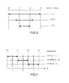
- Figure 3 illustrates different level of 3D intensity (or even a disparity level value, which is a parameter noted ⁇ ) with a four-cameras rig (which generate the views from T0 to T3) assuming that a minimum of disparity is maintained.
- the number of incoming views used could differ.
- the parameters ( ⁇ , ⁇ ) that are entered by a user are considered as the user's input.
- Figure 4 illustrates the principle of an adapted viewpoint on a four cameras system, according to one embodiment of the invention.
- This principle can of course be generalized to a case where more than four cameras system are used.
- Figure 5(a)-(d) present some examples of modifications of the depth level parameter and the viewpoint that are defined by a user positioned in front of a multi-view display device.
- the Figure 5(a) discloses an example of a modification of a viewpoint parameter (the parameter noted ⁇ , initially at a value -0.2) initially entered by a user via a user interface either provided by a display through the multi-view display device, or a device (such as a box with a display area) connected directly or indirectly (either via wireless means or via a cable means) to the multi-view display device.
- the disparity level is conserved (i.e. the value of the disparity level is not modified and is equal to 0.5).
- the modification changes the viewpoint parameter from -0.2 to -0.5.
- This modification induces a save of the bandwidth of the channel that links (directly or indirectly) the multi-view display device and the provider of the multi-views camera images (which can delivers the views camera images T0, T1, T2 and T3 in this example).
- the multi-view display device receives the four different views (as well as the associated disparity maps), however, in the modified configuration, it is not necessary to provide to the multi-view display device the view camera image T3. Therefore, around 25% of the bandwidth is saved by removing the transmission of T3.
- the variation of the viewpoint parameter is equal to 0.3 (where a value of one represents the distance between 2 views). For the viewpoint parameter having a range of -0.5/+0.5, it is possible to get such optimization (if we have equal distance between each camera).
- the Figure 5(b) discloses an example of a modification of a disparity level parameter (the parameter noted ⁇ , initially at a value 0.5) initially entered by a user via a user interface either provided by a display through the multi-view display device, or a device (such as a box with a display area) connected directly or indirectly (either via wireless means or via a cable means) to the multi-view display device.
- the viewpoint parameter is kept (i.e. the value of the viewpoint parameter is not modified and is equal to -0.2).
- the modification changes the viewpoint parameter from the value 0.5 to the value 0.3.
- This modification induces a save of the bandwidth of the channel that links (directly or indirectly) the multi-view display device and the provider of the multi-views camera images (which can delivers the views camera images T0, T1, T2 and T3 in this example).
- the multi-view display device receives the four different views (as well as the associated disparity maps), however, in the modified configuration, it is not necessary to provide to the multi-view display device the view camera image T3. Therefore, around 25% of the bandwidth is saved by removing the transmission of T3.
- the Figure 5(c) discloses an example of a modification of a disparity level parameter (the parameter noted ⁇ , initially at a value 0.5) and a viewpoint parameter (the parameter noted ⁇ , initially at a value -0.2), by a user via a user interface provided as explained previously.
- a disparity level parameter the parameter noted ⁇ , initially at a value 0.5
- a viewpoint parameter the parameter noted ⁇ , initially at a value -0.2
- the Figure 5(d) discloses an example of a modification of a disparity level parameter (the parameter noted ⁇ , initially at a value 0.5) and a viewpoint parameter (the parameter noted ⁇ , initially at a value -0.2), by a user via a user interface provided as explained previously.
- a disparity level parameter the parameter noted ⁇ , initially at a value 0.5
- a viewpoint parameter the parameter noted ⁇ , initially at a value -0.2
- Figure 6 presents a block diagram that focuses on some steps of the proposed technique according to one embodiment.
- a user interface (either displayed by a multi-view display device or a device (such as a box) connected to the multi-view display device) allows the user to enter the two parameters ( ⁇ , ⁇ ) that are corresponding respectively to the 3D intensity and the viewpoint position.
- the system has been defined in term of number of views available. In this case we consider a view as a video and its associated disparity map that will help the renderer to interpolate missing views.
- the two parameters ( ⁇ , ⁇ ) are set up according to some pre-criteria given by the user and some requirements related to bandwidth resources.
- a modified set of values ( ⁇ ', ⁇ ') is determined to obtain a tradeoff in term of the bandwidth required and the perception requirements of the user. For example in the context of the use of a peer-to-peer network in order to provide camera images to a multi-views camera images, a management block is selecting the views really required for the processing based on the modified ( ⁇ ', ⁇ ') values. Then the network is configured to transmit these views. They are received, processed and then displayed.
- the modified set of values ( ⁇ ', ⁇ ') are obtained from the user's input, as well as some bandwidth credentials/rights.
- a user who has subscribed to a premium service could only have his parameters ( ⁇ , ⁇ ) slightly modified (or even not modified at all), whereas, a user having done a cheap subscription to a service, is going to have his parameters ( ⁇ , ⁇ ) much more modified.
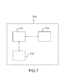
- Figure 7 presents an example of a device that can be used to perform one or several steps of methods disclosed in the present document.
- Such device can be part of a multi-view display device, or the multi-view display device itself.
- Such device referenced 700 comprises a computing unit (for example a CPU, for "Central Processing Unit"), referenced 701, and one or more memory units (for example a RAM (for "Random Access Memory” ) block in which intermediate results can be stored temporarily during the execution of instructions a computer program, or a ROM block in which, among other things, computer programs are stored, or an EEPROM ( "Electrically-Erasable Programmable Read-Only Memory” ) block, or a flash block) referenced 702.
- Computer programs are made of instructions that can be executed by the computing unit.
- Such device 700 can also comprise a dedicated unit, referenced 703, constituting an input-output interface to allow the device 700 to communicate with other devices.
- this dedicated unit 703 can be connected with an antenna (in order to perform communication without contacts), or with serial ports (to carry communications "contact"). It should be noted that the arrows in Figure 7 signify that the linked unit can exchange data through buses for example together.
- some or all of the steps of the method previously described can be implemented in hardware in a programmable FPGA ("Field Programmable Gate Array”) component or ASIC ("Application-Specific Integrated Circuit” ) component.
- a programmable FPGA Field Programmable Gate Array
- ASIC Application-Specific Integrated Circuit
- some or all of the steps of the method previously described can be executed on an electronic device comprising memory units and processing units as the one disclosed in the Figure 7 .
Landscapes
- Engineering & Computer Science (AREA)
- Multimedia (AREA)
- Signal Processing (AREA)
- Library & Information Science (AREA)
- Testing, Inspecting, Measuring Of Stereoscopic Televisions And Televisions (AREA)
Abstract
- obtaining a user's input being a depth level and/or a viewpoint;
- modifying said user's input in function of at least one configuration parameter, said modifying defining a group of images, said images from said group being spatially successive images of a scene at a same time; and
- displaying k-views on said multi-view display device, said k-views being obtained from a process taking into accounts elements from said group of images.
Description
- The invention relates to multi-view display devices that enable users to watch a 3D content without using dedicated glasses.
- This section is intended to introduce the reader to various aspects of art, which may be related to various aspects of the present invention that are described and/or claimed below. This discussion is believed to be helpful in providing the reader with background information to facilitate a better understanding of the various aspects of the present invention. Accordingly, it should be understood that these statements are to be read in this light, and not as admissions of prior art.
- An auto-stereoscopic display is a display device providing a 3D effect that can be perceived without any glasses. The simplest auto-stereoscopic display devices provide stereoscopic 3D rendering with only two views, they are based on parallax barriers. Multi-view auto-stereoscopic display devices based on lenticular network are able to generate more than 2 views to allow the viewer to be placed at different position seeing stereoscopic content. In this case, a network of lenses is added in front of the RGB sub-pixel matrix of a display. Thanks to these lenses, the light generated by the different sub-pixel R, G or B is generated in different directions, depending on the position of the sub-pixel relatively to the lens. When a user is placed in front of this display device, at a certain distance and position, he will receive on each eye only the light generated by some sub-pixels. To perceive the 3D effect without glasses, the user must receive on one eye the light of the sub-pixels generating a 3D view, and on the other eye the light of the sub-pixels generating another 3D view adjacent to the first one. The
figure 1 presents a simple scheme of multi-view auto-stereoscopic display device generating 8 views, according to the state of the art. In this example, the red (noted R onfigure 1 )sub-pixel 0 and the blue (noted B infigure 1 )sub-pixel 8 will generate the view V7. The green (noted G onfigure 1 )sub-pixel 1 and thered sub-pixel 9 will generate the view V6, and so on up to the view V0 generated by thegreen sub-pixel 7 and thered sub-pixel 15. With such a scheme, a RGB pixel generates the information corresponding to three different views. - A preferred scheme, disclosed in
figure 2 , is to transmit some of the views with some associated disparity maps to an auto-stereoscopic display, and then such auto-stereoscopic display interpolates the missing views in order to provide the appropriated number of views that the auto-stereoscopic display supports. At the acquisition side, if we consider a four cameras system we must then transmit four views and four associated disparity map. The display is the able to interpolate the missing views. - However, a drawback of this scheme is that the amount of data to be transmitted (e.g. the images (which are images of a same scene that were generated by several cameras positioned in several position corresponding to a view, such images being not necessarily interpolated), as well as the associated disparity maps) is quite high. Indeed, the more views the auto-stereoscopic display received from a device providing the images and the disparity maps, the heavier the bandwidth load is. Such issue can be critical in some context in which the bandwidth management is a difficult issue to handle.
- In order to solve this issue, one skilled in the art would have reduced arbitrarily the number of transmitted multi-views camera images, as well as the corresponding disparity map. Then, by using a stereo-to-multiview conversion technique (as for example the one depicted in the document entitled " Fully Automatic Conversion of Stereo to Multiview for Autostereoscopic Displays" by C. Riechert et al., published in the proceedings of the conference IBC 2012), the auto-stereoscopic display could still display the same number of views. The reduction is set up when a monitoring of the bandwidth provides information indicating that the bandwidth is saturated (or beyond a pre-defined level). In a variant, in order to solve this issue, one skilled in the art would have reduced only the number of transmitted disparity maps, as the missing (i.e. not received) disparity maps can be computed within the auto-stereoscopic display.
- The proposed technique proposes an alternative to these techniques.
- The present invention is directed to a method for displaying a 3D content on a multi-view display device, said multi-view display device being able to display k-views, with k an integer greater or equal to two. The method is implemented on said multi-view display device, and is remarkable in that it comprises:
- obtaining a user's input being a depth level and/or a viewpoint;
- modifying said user's input in function of at least one configuration parameter, said modifying defining a group of images, said images from said group being spatially successive images of a scene at a same time; and
- displaying k-views on said multi-view display device, said k-views being obtained from a process taking into accounts elements from said group of images.
- Such at least one configuration parameter is a service provider's definable setting.
- A user that is positioned in front of said multi-view display device can enter these user's input. When the user is in front of said multi-view display device, it means that said user is able to watch 3D content through said multi-view display device (e.g. the multi-view display device is comprised within the user's field view).
- In a preferred embodiment, the method for displaying is remarkable in that said at least one configuration parameter corresponds to a bandwidth credential associated with said user.
- In a preferred embodiment, the method for displaying is remarkable in that it comprises transmitting a number of images, corresponding to a cardinality of said group of images, to a device that provides said group of images to said multi-view display device.
- In a preferred embodiment, the method for displaying is remarkable in that said number of images is greater or equal to three. In a preferred embodiment, the method for displaying is remarkable in that said depth level corresponds to a perceived 3D intensity parameter.
- In a preferred embodiment, the method for displaying is remarkable in that said viewpoint is defined in function of a first image and a second image, said first image and second successive image belonging to said group of images.
- In a preferred embodiment, the method for displaying is remarkable in that said obtaining corresponds to receiving from a device said group of images.
- In a preferred embodiment, the method for displaying is remarkable in that it further comprises obtaining a group of disparity maps.
- In a preferred embodiment, the method for displaying is remarkable in that said multi-view display device is an auto-stereoscopic screen.
- In a preferred embodiment, the method for displaying is remarkable in that said multi-view display device is a radio communication device comprising an auto-stereoscopic screen.
- According to an exemplary implementation, the different steps of the method are implemented by a computer software program or programs, this software program comprising software instructions designed to be executed by a data processor of a relay module according to the disclosure and being designed to control the execution of the different steps of this method.
- Consequently, an aspect of the disclosure also concerns a program liable to be executed by a computer or by a data processor, this program comprising instructions to command the execution of the steps of a method as mentioned here above.
- This program can use any programming language whatsoever and be in the form of a source code, object code or code that is intermediate between source code and object code, such as in a partially compiled form or in any other desirable form.
- The disclosure also concerns an information medium readable by a data processor and comprising instructions of a program as mentioned here above.
- The information medium can be any entity or device capable of storing the program. For example, the medium can comprise a storage means such as a ROM (which stands for "Read Only Memory"), for example a CD-ROM (which stands for "Compact Disc - Read Only Memory") or a microelectronic circuit ROM or again a magnetic recording means, for example a floppy disk or a hard disk drive.
- Furthermore, the information medium may be a transmissible carrier such as an electrical or optical signal that can be conveyed through an electrical or optical cable, by radio or by other means. The program can be especially downloaded into an Internet-type network.
- Alternately, the information medium can be an integrated circuit into which the program is incorporated, the circuit being adapted to executing or being used in the execution of the method in question.
- According to one embodiment, an embodiment of the disclosure is implemented by means of software and/or hardware components. From this viewpoint, the term "module" can correspond in this document both to a software component and to a hardware component or to a set of hardware and software components.
- A software component corresponds to one or more computer programs, one or more sub-programs of a program, or more generally to any element of a program or a software program capable of implementing a function or a set of functions according to what is described here below for the module concerned. One such software component is executed by a data processor of a physical entity (terminal, server, etc.) and is capable of accessing the hardware resources of this physical entity (memories, recording media, communications buses, input/output electronic boards, user interfaces, etc.).
- Similarly, a hardware component corresponds to any element of a hardware unit capable of implementing a function or a set of functions according to what is described here below for the module concerned. It may be a programmable hardware component or a component with an integrated circuit for the execution of software, for example an integrated circuit, a smart card, a memory card, an electronic board for executing firmware etc. In a variant, the hardware component (also named hardare means) comprises a processor that is an integrated circuit such as a central processing unit, and/or a microprocessor, and/or an Application-specific integrated circuit (ASIC), and/or an Application-specific instruction-set processor (ASIP), and/or a graphics processing unit (GPU), and/or a physics processing unit (PPU), and/or a digital signal processor (DSP), and/or an image processor, and/or a coprocessor, and/or a floating-point unit, and/or a network processor, and/or an audio processor, and/or a multi-core processor. Moreover, the hardware component can also comprise a baseband processor (comprising for example memory units, and a firmware) and/or radio electronic circuits (that can comprise antennas) which receive or transmit radio signals. In one embodiment, the hardware component is compliant one or more standards such as ISO/IEC 18092 / ECMA-340, ISO/IEC 21481 / ECMA-352, GSMA, StoLPaN, ETSI / SCP (Smart Card Platform), GlobalPlatform (i.e. a secure element). In a variant, the hardware component is a Radio-frequency identification (RFID) tag. In one embodiment, a hardware component comprises circuits that enable Bluetooth communications, and/or Wi-fi communications, and/or Zigbee communications, and/or USB communications and/or Firewire communications.
- It should also be noted that a step of obtaining an element/value in the present document can be viewed either as a step of reading such element/value in a memory unit of an electronic device or a step of receiving such element/value from another electronic device via communication means.
- In another embodiment, it is proposed a multi-view display device being able to display k-views, with k an integer greater or equal to two. The multi-view display device is remarkable in that it comprises:
- means for obtaining a user's input being a depth level and/or a viewpoint;
- means for modifying said user's input in function of at least one configuration parameter, said modifying defining a group of images, said images from said group being spatially successive images of a scene at a same time;
- means for displaying k-views on said multi-view display device, said k-views being obtained from a process taking into accounts elements from said group of images.
- In a variant, the multi-view display device is remarkable in that said at least one configuration parameter corresponds to a bandwidth credential associated to said user.
- In a variant, the multi-view display device is remarkable in that it comprises means for transmitting a number of images, corresponding to a cardinality of said group of images, to a device that provides said group of images to said multi-view display device.
- In a variant, the multi-view display device is remarkable in that said number of images is greater or equal to three.
- The above and other aspects of the invention will become more apparent by the following detailed description of exemplary embodiments thereof with reference to the attached drawings in which:
-
Figure 1 presents a sectional view of a part of an auto stereoscopic display device which is an example of a multi-view display device; -
Figure 2 presents an example of generation of eight different views from four images, corresponding to four different views (and associated disparity maps), the generation being performed by a multi-view display device which obtains (or received) the four images from another device; -
Figure 3 illustrates different level of 3D intensity (or disparity level value, which is a parameter noted α) with a four cameras rig (which generate the views from T0 to T3) assuming that the minimum disparity is maintained, according to one embodiment of the invention; -
Figure 4 illustrates the principle of an adapted viewpoint on a four cameras system, according to one embodiment of the invention; -
Figure 5(a)-(d) present some examples of modifications of the depth level parameter and the viewpoint that are defined by a user positioned in front of a multi-view display device, and are modified according to several embodiments of the invention; -
Figure 6 presents a block diagram that focuses on some steps of the proposed technique according to one embodiment; -
Figure 7 presents an example of a device that can be used to perform one or several steps of methods disclosed in the present document. -
Figure 1 presents a sectional view of a part of an auto stereoscopic display device, which is an example of a multi-view display device. - Usually, an auto stereoscopic display device comprises an array of pixels (which comprises
pixel 0 to 4), and a lenticular array (which compriseslens 0 and lens 1) superposed to said array of pixels. Said array of pixels comprises a plurality of sub-pixels which are disposed on a substrate (not represented). Each sub-pixel is associated to a color (either green, or blue, or bleu) and to a view (due to the properties (shape, etc.) of the lenticular array. The part of an auto stereoscopic display device disclosed inFigure 1 discloses some of these elements. -
Figure 2 presents an example of generation of eight different views from four images corresponding to four different views (and associated disparity maps), the generation being performed by a multi-view display device which obtains (or received) the four images from another device. - Usually, a multi-view display device receives several images (each of the images being associated to a view that can be for example a view corresponding to the position of a camera which was used to obtain such image; in a variant, the images are obtained from a conversion technique such as the one previously mentioned), the number of the images transmitted being defined by a service provider.
- The perceived disparity on multi-view screens corresponds to the disparity between two adjacent views (these adjacent views are the views obtained after an interpolation process for example). In a k-cameras rig (generating k images at a given time), the disparity max perceived dmp can be approximated to the sum of disparity max for each pair of views divided by the number of views (noted nbv) of the display:

- In the context depicted in
Figure 2 , the four images received by the multi-view display device, as well as the received disparity maps are used to generate eight different views via an interpolation process as know by one skilled in the state of the art. - The proposed technique enables to save some bandwidth by reducing the amount of information transmitted to a multi-view display device. Details of the proposed technique are given in the followings figures and corresponding descriptions. More precisely, with the proposed technique, a user of the multi-view display device is able to reduce such amount of information, by modifying his requirements related to the intensity of 3D to be perceived, and/or related to the views to be perceived. Moreover, in function of some parameters (such as a bandwidth credential associated to a user), these requirements are modified/adjusted. Hence, a gap between what user enters and what he gets can occur. However, the modifications induced by these modifications, are slightly perceptible.
-
Figure 3 illustrates different level of 3D intensity (or even a disparity level value, which is a parameter noted α) with a four-cameras rig (which generate the views from T0 to T3) assuming that a minimum of disparity is maintained. Depending of the value of the parameter α, the number of incoming views used could differ. Then the adjusted disparity dadj can be expressed as :
- With multi-view screens it is possible to see different views of the same image by slightly moving the head inside the sweet spot. In a k-cameras rig system, it could be possible to choose some specific viewpoints. A β parameter is introduced to define the viewpoint positioning compared to a central one (in such case, we have β=0). The parameters (α,β) that are entered by a user are considered as the user's input.
-
Figure 4 illustrates the principle of an adapted viewpoint on a four cameras system, according to one embodiment of the invention. - The LEFT case is corresponding to a multi-view content from T0-T1 with α=0 and β= -1. The CENTRAL case is corresponding to a multi-view content from T1-T2 with α=0 and β= 0. The RIGHT case is corresponding to a multi-view content from T2-T3 with α=0 and β= +1.
- This principle can of course be generalized to a case where more than four cameras system are used.
-
Figure 5(a)-(d) present some examples of modifications of the depth level parameter and the viewpoint that are defined by a user positioned in front of a multi-view display device. - More precisely, the
Figure 5(a) discloses an example of a modification of a viewpoint parameter (the parameter noted β, initially at a value -0.2) initially entered by a user via a user interface either provided by a display through the multi-view display device, or a device (such as a box with a display area) connected directly or indirectly (either via wireless means or via a cable means) to the multi-view display device. In this example, the disparity level is conserved (i.e. the value of the disparity level is not modified and is equal to 0.5). The modification changes the viewpoint parameter from -0.2 to -0.5. This modification induces a save of the bandwidth of the channel that links (directly or indirectly) the multi-view display device and the provider of the multi-views camera images (which can delivers the views camera images T0, T1, T2 and T3 in this example). Indeed, in the initial configuration, it is necessary that the multi-view display device receives the four different views (as well as the associated disparity maps), however, in the modified configuration, it is not necessary to provide to the multi-view display device the view camera image T3. Therefore, around 25% of the bandwidth is saved by removing the transmission of T3. In this example, the variation of the viewpoint parameter is equal to 0.3 (where a value of one represents the distance between 2 views). For the viewpoint parameter having a range of -0.5/+0.5, it is possible to get such optimization (if we have equal distance between each camera). - The
Figure 5(b) discloses an example of a modification of a disparity level parameter (the parameter noted α, initially at a value 0.5) initially entered by a user via a user interface either provided by a display through the multi-view display device, or a device (such as a box with a display area) connected directly or indirectly (either via wireless means or via a cable means) to the multi-view display device. In this example, the viewpoint parameter is kept (i.e. the value of the viewpoint parameter is not modified and is equal to -0.2). The modification changes the viewpoint parameter from the value 0.5 to the value 0.3. This modification induces a save of the bandwidth of the channel that links (directly or indirectly) the multi-view display device and the provider of the multi-views camera images (which can delivers the views camera images T0, T1, T2 and T3 in this example). Indeed, in the initial configuration, it is necessary that the multi-view display device receives the four different views (as well as the associated disparity maps), however, in the modified configuration, it is not necessary to provide to the multi-view display device the view camera image T3. Therefore, around 25% of the bandwidth is saved by removing the transmission of T3. - The
Figure 5(c) discloses an example of a modification of a disparity level parameter (the parameter noted α, initially at a value 0.5) and a viewpoint parameter (the parameter noted β, initially at a value -0.2), by a user via a user interface provided as explained previously. In that case, both the disparity level parameter and the viewpoint parameter are modified such that it is not necessary to transmit some views. Therefore, the user is able to modify these two parameters in such way that he fulfils the expected requirements in term of bandwidth use. - The
Figure 5(d) discloses an example of a modification of a disparity level parameter (the parameter noted α, initially at a value 0.5) and a viewpoint parameter (the parameter noted β, initially at a value -0.2), by a user via a user interface provided as explained previously. In that case, we consider a MVC-like coding where video are not encoded separately but commonly two-by-two (e.g. MVC encoding). In this case such optimization makes sense if the two adjacent views can be removed. In this case we assume that the views T0 and T1 are encoded together. Hence, by modifying the disparity level parameter to a value equaled to 0, and the viewpoint parameter to the value -1), it is possible to obtain a reduction of bandwidth equals to 50%. - More generally for any transmission scheme including at least n views (n≥3) and for a given user requirement (α,β) with α>0 and |β|≠1, the modified values could be equal to (α',β') with α'=α- δa and β'= β+ δβ for which the final number of views required is reduced by at least one: n'≤n-1 (with δα > 0 and -1<δβ<1).
-
Figure 6 presents a block diagram that focuses on some steps of the proposed technique according to one embodiment. - A user interface (either displayed by a multi-view display device or a device (such as a box) connected to the multi-view display device) allows the user to enter the two parameters (α,β) that are corresponding respectively to the 3D intensity and the viewpoint position. In parallel to this the system has been defined in term of number of views available. In this case we consider a view as a video and its associated disparity map that will help the renderer to interpolate missing views. In another embodiment, the two parameters (α,β) are set up according to some pre-criteria given by the user and some requirements related to bandwidth resources. Hence, based on initial (α,β) values and some requirements related to the transmission scheme (that defines the constraints on the bandwidth resources), a modified set of values (α',β') is determined to obtain a tradeoff in term of the bandwidth required and the perception requirements of the user. For example in the context of the use of a peer-to-peer network in order to provide camera images to a multi-views camera images, a management block is selecting the views really required for the processing based on the modified (α',β') values. Then the network is configured to transmit these views. They are received, processed and then displayed. In a variant, according to the terms of a user's subscription to a service provider, the modified set of values (α',β') are obtained from the user's input, as well as some bandwidth credentials/rights. For example, a user who has subscribed to a premium service could only have his parameters (α,β) slightly modified (or even not modified at all), whereas, a user having done a cheap subscription to a service, is going to have his parameters (α,β) much more modified.
-
Figure 7 presents an example of a device that can be used to perform one or several steps of methods disclosed in the present document. - Such device can be part of a multi-view display device, or the multi-view display device itself. Such device referenced 700 comprises a computing unit (for example a CPU, for "Central Processing Unit"), referenced 701, and one or more memory units (for example a RAM (for "Random Access Memory") block in which intermediate results can be stored temporarily during the execution of instructions a computer program, or a ROM block in which, among other things, computer programs are stored, or an EEPROM ("Electrically-Erasable Programmable Read-Only Memory") block, or a flash block) referenced 702. Computer programs are made of instructions that can be executed by the computing unit.
Such device 700 can also comprise a dedicated unit, referenced 703, constituting an input-output interface to allow thedevice 700 to communicate with other devices. In particular, thisdedicated unit 703 can be connected with an antenna (in order to perform communication without contacts), or with serial ports (to carry communications "contact"). It should be noted that the arrows inFigure 7 signify that the linked unit can exchange data through buses for example together. - In an alternative embodiment, some or all of the steps of the method previously described, can be implemented in hardware in a programmable FPGA ("Field Programmable Gate Array") component or ASIC ("Application-Specific Integrated Circuit") component.
- In an alternative embodiment, some or all of the steps of the method previously described, can be executed on an electronic device comprising memory units and processing units as the one disclosed in the
Figure 7 .
Claims (13)
- A method for displaying a 3D content on a multi-view display device, said multi-view display device being operable to display k-views, with k an integer greater or equal to two, said method being implemented on said multi-view display device, and being characterized in that it comprises :- modifying at least one of a depth level and a viewpoint of a scene obtained from a user input, the modification being based on at least a bandwidth parameter associated with said user, said modifying defining a group of images, said images from said group being spatially successive images of the scene at a same time;- and- displaying k-views of the scene on said multi-view display device, said k-views being obtained from said group of images.
- The method for displaying according to claim 1, characterized in that it comprises transmitting a number of images corresponding to a cardinality of said group of images to a device that provides said group of images to said multi-view display device.
- The method for displaying according to claim 2 , characterized in that said number of images is greater than or equal to three.
- The method for displaying according to any claims 1 to 3, characterized in that said depth level corresponds to a perceived 3D intensity parameter.
- The method for displaying according to any claims 1 to 4, characterized in that said viewpoint is defined as a function of a first image and a second image, said first image and second image belonging to said group of images.
- The method for displaying according to any claims 1 to 5, characterized in that it comprises receiving from a device said group of images.
- The method for displaying according to any claims 1 to 6, characterized in that it further comprises obtaining a group of disparity maps.
- The method for displaying according to any claims 1 to 7, characterized in that said multi-view display device is an auto-stereoscopic screen.
- The method for displaying according to any claims 1 to 7, characterized in that said multi-view display device is a radio communication device comprising an auto-stereoscopic screen.
- A computer-readable and non-transient storage medium storing a computer program comprising a set of computer-executable instructions to implement a method for displaying a 3D content when the instructions are executed by a computer, wherein the instructions comprise instructions, which when executed, configure the computer to perform a method of claims 1 to 9.
- A multi-view display device being operable to display k-views, with k an integer greater or equal to two, and being characterized in that it comprises:- means for modifying at least one of a depth level and a viewpoint of a scene obtained from a user input, the modification being based on at least a bandwidth parameter associated with said user, said modifying defining a group of images, said images from said group being spatially successive images of the scene at a same time; and- means for displaying k-views of the scene on said multi-view display device, said k-views being obtained from said group of images.
- The multi-view display device according to claim 11, characterized in that it comprises means for transmitting a number of images corresponding to a cardinality of said group of images to a device that provides said group of images to said multi-view display device.
- The multi-view display device according to any claims 11 to 12, characterized in that said number of images is greater than or equal to three.
Priority Applications (1)
| Application Number | Priority Date | Filing Date | Title |
|---|---|---|---|
| EP15154941.7A EP2908520B1 (en) | 2014-02-14 | 2015-02-13 | Method for displaying a 3D content on a multi-view display device, corresponding multi-view display device and computer program product |
Applications Claiming Priority (2)
| Application Number | Priority Date | Filing Date | Title |
|---|---|---|---|
| EP14305191.0A EP2908519A1 (en) | 2014-02-14 | 2014-02-14 | Method for displaying a 3D content on a multi-view display device, corresponding multi-view display device and computer program product |
| EP15154941.7A EP2908520B1 (en) | 2014-02-14 | 2015-02-13 | Method for displaying a 3D content on a multi-view display device, corresponding multi-view display device and computer program product |
Publications (2)
| Publication Number | Publication Date |
|---|---|
| EP2908520A1 true EP2908520A1 (en) | 2015-08-19 |
| EP2908520B1 EP2908520B1 (en) | 2018-10-31 |
Family
ID=50241333
Family Applications (2)
| Application Number | Title | Priority Date | Filing Date |
|---|---|---|---|
| EP14305191.0A Withdrawn EP2908519A1 (en) | 2014-02-14 | 2014-02-14 | Method for displaying a 3D content on a multi-view display device, corresponding multi-view display device and computer program product |
| EP15154941.7A Not-in-force EP2908520B1 (en) | 2014-02-14 | 2015-02-13 | Method for displaying a 3D content on a multi-view display device, corresponding multi-view display device and computer program product |
Family Applications Before (1)
| Application Number | Title | Priority Date | Filing Date |
|---|---|---|---|
| EP14305191.0A Withdrawn EP2908519A1 (en) | 2014-02-14 | 2014-02-14 | Method for displaying a 3D content on a multi-view display device, corresponding multi-view display device and computer program product |
Country Status (2)
| Country | Link |
|---|---|
| US (1) | US9967551B2 (en) |
| EP (2) | EP2908519A1 (en) |
Families Citing this family (1)
| Publication number | Priority date | Publication date | Assignee | Title |
|---|---|---|---|---|
| CN109194948A (en) * | 2018-10-30 | 2019-01-11 | 安徽虚空位面信息科技有限公司 | Mobile naked eye 3D display system |
Citations (3)
| Publication number | Priority date | Publication date | Assignee | Title |
|---|---|---|---|---|
| EP1519582A1 (en) * | 2002-06-28 | 2005-03-30 | Sharp Kabushiki Kaisha | Image data delivery system, image data transmitting device thereof, and image data receiving device thereof |
| WO2011062572A1 (en) * | 2009-11-18 | 2011-05-26 | Thomson Licensing | Methods and systems for three dimensional content delivery with flexible disparity selection |
| US20130038606A1 (en) * | 2011-08-08 | 2013-02-14 | Suguru USHIKI | Image processing apparatus, image processing method, and program |
Family Cites Families (2)
| Publication number | Priority date | Publication date | Assignee | Title |
|---|---|---|---|---|
| US8094927B2 (en) * | 2004-02-27 | 2012-01-10 | Eastman Kodak Company | Stereoscopic display system with flexible rendering of disparity map according to the stereoscopic fusing capability of the observer |
| JP2015516751A (en) * | 2012-04-13 | 2015-06-11 | コーニンクレッカ フィリップス エヌ ヴェ | Depth signaling data |
-
2014
- 2014-02-14 EP EP14305191.0A patent/EP2908519A1/en not_active Withdrawn
-
2015
- 2015-02-12 US US14/620,670 patent/US9967551B2/en not_active Expired - Fee Related
- 2015-02-13 EP EP15154941.7A patent/EP2908520B1/en not_active Not-in-force
Patent Citations (3)
| Publication number | Priority date | Publication date | Assignee | Title |
|---|---|---|---|---|
| EP1519582A1 (en) * | 2002-06-28 | 2005-03-30 | Sharp Kabushiki Kaisha | Image data delivery system, image data transmitting device thereof, and image data receiving device thereof |
| WO2011062572A1 (en) * | 2009-11-18 | 2011-05-26 | Thomson Licensing | Methods and systems for three dimensional content delivery with flexible disparity selection |
| US20130038606A1 (en) * | 2011-08-08 | 2013-02-14 | Suguru USHIKI | Image processing apparatus, image processing method, and program |
Non-Patent Citations (2)
| Title |
|---|
| C. RIECHERT ET AL.: "Fully Automatic Conversion of Stereo to Multiview for Autostereoscopic Displays", THE PROCEEDINGS OF THE CONFERENCE IBC, 2012 |
| ILKWON PARK ET AL: "Interactive Multi-View Video Adaptation for 3DTV", 3DTV CONFERENCE: THE TRUE VISION - CAPTURE, TRANSMISSION AND DISPLAY OF 3D VIDEO, 2008, IEEE, PISCATAWAY, NJ, USA, 28 May 2008 (2008-05-28), pages 89 - 92, XP031275218, ISBN: 978-1-4244-1760-5 * |
Also Published As
| Publication number | Publication date |
|---|---|
| US20150237332A1 (en) | 2015-08-20 |
| EP2908519A1 (en) | 2015-08-19 |
| EP2908520B1 (en) | 2018-10-31 |
| US9967551B2 (en) | 2018-05-08 |
Similar Documents
| Publication | Publication Date | Title |
|---|---|---|
| EP3289413B1 (en) | Method and device for processing a lightfield content | |
| US8884952B2 (en) | 3D display apparatus and method for processing image using the same | |
| CN103081476B (en) | Method and device for converting 3D image using depth map information | |
| US20120113219A1 (en) | Image conversion apparatus and display apparatus and methods using the same | |
| CN104081768B (en) | Different visual point image generating means and different visual point image generating method | |
| EP2801200B1 (en) | Display processor for 3d display | |
| CN102932664B (en) | Playing method of video of naked 3D (three-dimensional) television wall | |
| KR20150049952A (en) | multi view image display apparatus and control method thereof | |
| US20250299428A1 (en) | Layered view synthesis system and method | |
| CN104335579A (en) | Method of encoding a video data signal for use with a multi-view stereoscopic display device | |
| CN102349304A (en) | Image display device, image generation device, image display method, image generation method, and non-transitory computer-readable medium in which program is stored | |
| KR20110113923A (en) | Image conversion device and stereoscopic image display device including the same | |
| US20120007951A1 (en) | System and format for encoding data and three-dimensional rendering | |
| EP3038361B1 (en) | A method for adapting a number of views delivered by an auto-stereoscopic display device, and corresponding computer program product and electronic device | |
| WO2015115946A1 (en) | Methods for encoding and decoding three-dimensional video content | |
| EP2908520B1 (en) | Method for displaying a 3D content on a multi-view display device, corresponding multi-view display device and computer program product | |
| EP2745520B1 (en) | Auxiliary information map upsampling | |
| EP3185551A1 (en) | Tridimensional rendering with adjustable disparity direction | |
| US9521428B2 (en) | Method, device and system for resizing original depth frame into resized depth frame | |
| US20160286198A1 (en) | Apparatus and method of converting image | |
| CN102780900A (en) | Image display method of multi-person multi-view stereoscopic display | |
| EP3935831B1 (en) | Depth map processing | |
| KR20200016363A (en) | Method for displaying content derived from light field data on a 2D display device | |
| KR20120059367A (en) | Apparatus for processing image based on energy value, and methods thereof | |
| CN104185005A (en) | Image processing apparatus and image processing method |
Legal Events
| Date | Code | Title | Description |
|---|---|---|---|
| PUAI | Public reference made under article 153(3) epc to a published international application that has entered the european phase |
Free format text: ORIGINAL CODE: 0009012 |
|
| AK | Designated contracting states |
Kind code of ref document: A1 Designated state(s): AL AT BE BG CH CY CZ DE DK EE ES FI FR GB GR HR HU IE IS IT LI LT LU LV MC MK MT NL NO PL PT RO RS SE SI SK SM TR |
|
| AX | Request for extension of the european patent |
Extension state: BA ME |
|
| 17P | Request for examination filed |
Effective date: 20160212 |
|
| RBV | Designated contracting states (corrected) |
Designated state(s): AL AT BE BG CH CY CZ DE DK EE ES FI FR GB GR HR HU IE IS IT LI LT LU LV MC MK MT NL NO PL PT RO RS SE SI SK SM TR |
|
| 17Q | First examination report despatched |
Effective date: 20160623 |
|
| STAA | Information on the status of an ep patent application or granted ep patent |
Free format text: STATUS: EXAMINATION IS IN PROGRESS |
|
| GRAP | Despatch of communication of intention to grant a patent |
Free format text: ORIGINAL CODE: EPIDOSNIGR1 |
|
| STAA | Information on the status of an ep patent application or granted ep patent |
Free format text: STATUS: GRANT OF PATENT IS INTENDED |
|
| INTG | Intention to grant announced |
Effective date: 20180530 |
|
| GRAS | Grant fee paid |
Free format text: ORIGINAL CODE: EPIDOSNIGR3 |
|
| GRAA | (expected) grant |
Free format text: ORIGINAL CODE: 0009210 |
|
| STAA | Information on the status of an ep patent application or granted ep patent |
Free format text: STATUS: THE PATENT HAS BEEN GRANTED |
|
| AK | Designated contracting states |
Kind code of ref document: B1 Designated state(s): AL AT BE BG CH CY CZ DE DK EE ES FI FR GB GR HR HU IE IS IT LI LT LU LV MC MK MT NL NO PL PT RO RS SE SI SK SM TR |
|
| REG | Reference to a national code |
Ref country code: CH Ref legal event code: EP Ref country code: GB Ref legal event code: FG4D |
|
| REG | Reference to a national code |
Ref country code: AT Ref legal event code: REF Ref document number: 1060813 Country of ref document: AT Kind code of ref document: T Effective date: 20181115 |
|
| REG | Reference to a national code |
Ref country code: DE Ref legal event code: R096 Ref document number: 602015018939 Country of ref document: DE |
|
| REG | Reference to a national code |
Ref country code: IE Ref legal event code: FG4D |
|
| REG | Reference to a national code |
Ref country code: NL Ref legal event code: MP Effective date: 20181031 |
|
| REG | Reference to a national code |
Ref country code: LT Ref legal event code: MG4D |
|
| REG | Reference to a national code |
Ref country code: AT Ref legal event code: MK05 Ref document number: 1060813 Country of ref document: AT Kind code of ref document: T Effective date: 20181031 |
|
| PG25 | Lapsed in a contracting state [announced via postgrant information from national office to epo] |
Ref country code: ES Free format text: LAPSE BECAUSE OF FAILURE TO SUBMIT A TRANSLATION OF THE DESCRIPTION OR TO PAY THE FEE WITHIN THE PRESCRIBED TIME-LIMIT Effective date: 20181031 Ref country code: IS Free format text: LAPSE BECAUSE OF FAILURE TO SUBMIT A TRANSLATION OF THE DESCRIPTION OR TO PAY THE FEE WITHIN THE PRESCRIBED TIME-LIMIT Effective date: 20190228 Ref country code: HR Free format text: LAPSE BECAUSE OF FAILURE TO SUBMIT A TRANSLATION OF THE DESCRIPTION OR TO PAY THE FEE WITHIN THE PRESCRIBED TIME-LIMIT Effective date: 20181031 Ref country code: PL Free format text: LAPSE BECAUSE OF FAILURE TO SUBMIT A TRANSLATION OF THE DESCRIPTION OR TO PAY THE FEE WITHIN THE PRESCRIBED TIME-LIMIT Effective date: 20181031 Ref country code: LV Free format text: LAPSE BECAUSE OF FAILURE TO SUBMIT A TRANSLATION OF THE DESCRIPTION OR TO PAY THE FEE WITHIN THE PRESCRIBED TIME-LIMIT Effective date: 20181031 Ref country code: FI Free format text: LAPSE BECAUSE OF FAILURE TO SUBMIT A TRANSLATION OF THE DESCRIPTION OR TO PAY THE FEE WITHIN THE PRESCRIBED TIME-LIMIT Effective date: 20181031 Ref country code: BG Free format text: LAPSE BECAUSE OF FAILURE TO SUBMIT A TRANSLATION OF THE DESCRIPTION OR TO PAY THE FEE WITHIN THE PRESCRIBED TIME-LIMIT Effective date: 20190131 Ref country code: LT Free format text: LAPSE BECAUSE OF FAILURE TO SUBMIT A TRANSLATION OF THE DESCRIPTION OR TO PAY THE FEE WITHIN THE PRESCRIBED TIME-LIMIT Effective date: 20181031 Ref country code: NO Free format text: LAPSE BECAUSE OF FAILURE TO SUBMIT A TRANSLATION OF THE DESCRIPTION OR TO PAY THE FEE WITHIN THE PRESCRIBED TIME-LIMIT Effective date: 20190131 Ref country code: AT Free format text: LAPSE BECAUSE OF FAILURE TO SUBMIT A TRANSLATION OF THE DESCRIPTION OR TO PAY THE FEE WITHIN THE PRESCRIBED TIME-LIMIT Effective date: 20181031 |
|
| PG25 | Lapsed in a contracting state [announced via postgrant information from national office to epo] |
Ref country code: RS Free format text: LAPSE BECAUSE OF FAILURE TO SUBMIT A TRANSLATION OF THE DESCRIPTION OR TO PAY THE FEE WITHIN THE PRESCRIBED TIME-LIMIT Effective date: 20181031 Ref country code: GR Free format text: LAPSE BECAUSE OF FAILURE TO SUBMIT A TRANSLATION OF THE DESCRIPTION OR TO PAY THE FEE WITHIN THE PRESCRIBED TIME-LIMIT Effective date: 20190201 Ref country code: SE Free format text: LAPSE BECAUSE OF FAILURE TO SUBMIT A TRANSLATION OF THE DESCRIPTION OR TO PAY THE FEE WITHIN THE PRESCRIBED TIME-LIMIT Effective date: 20181031 Ref country code: NL Free format text: LAPSE BECAUSE OF FAILURE TO SUBMIT A TRANSLATION OF THE DESCRIPTION OR TO PAY THE FEE WITHIN THE PRESCRIBED TIME-LIMIT Effective date: 20181031 Ref country code: PT Free format text: LAPSE BECAUSE OF FAILURE TO SUBMIT A TRANSLATION OF THE DESCRIPTION OR TO PAY THE FEE WITHIN THE PRESCRIBED TIME-LIMIT Effective date: 20190301 Ref country code: AL Free format text: LAPSE BECAUSE OF FAILURE TO SUBMIT A TRANSLATION OF THE DESCRIPTION OR TO PAY THE FEE WITHIN THE PRESCRIBED TIME-LIMIT Effective date: 20181031 |
|
| PG25 | Lapsed in a contracting state [announced via postgrant information from national office to epo] |
Ref country code: DK Free format text: LAPSE BECAUSE OF FAILURE TO SUBMIT A TRANSLATION OF THE DESCRIPTION OR TO PAY THE FEE WITHIN THE PRESCRIBED TIME-LIMIT Effective date: 20181031 Ref country code: IT Free format text: LAPSE BECAUSE OF FAILURE TO SUBMIT A TRANSLATION OF THE DESCRIPTION OR TO PAY THE FEE WITHIN THE PRESCRIBED TIME-LIMIT Effective date: 20181031 Ref country code: CZ Free format text: LAPSE BECAUSE OF FAILURE TO SUBMIT A TRANSLATION OF THE DESCRIPTION OR TO PAY THE FEE WITHIN THE PRESCRIBED TIME-LIMIT Effective date: 20181031 |
|
| REG | Reference to a national code |
Ref country code: DE Ref legal event code: R097 Ref document number: 602015018939 Country of ref document: DE |
|
| PG25 | Lapsed in a contracting state [announced via postgrant information from national office to epo] |
Ref country code: SK Free format text: LAPSE BECAUSE OF FAILURE TO SUBMIT A TRANSLATION OF THE DESCRIPTION OR TO PAY THE FEE WITHIN THE PRESCRIBED TIME-LIMIT Effective date: 20181031 Ref country code: RO Free format text: LAPSE BECAUSE OF FAILURE TO SUBMIT A TRANSLATION OF THE DESCRIPTION OR TO PAY THE FEE WITHIN THE PRESCRIBED TIME-LIMIT Effective date: 20181031 Ref country code: SM Free format text: LAPSE BECAUSE OF FAILURE TO SUBMIT A TRANSLATION OF THE DESCRIPTION OR TO PAY THE FEE WITHIN THE PRESCRIBED TIME-LIMIT Effective date: 20181031 Ref country code: EE Free format text: LAPSE BECAUSE OF FAILURE TO SUBMIT A TRANSLATION OF THE DESCRIPTION OR TO PAY THE FEE WITHIN THE PRESCRIBED TIME-LIMIT Effective date: 20181031 |
|
| PLBE | No opposition filed within time limit |
Free format text: ORIGINAL CODE: 0009261 |
|
| STAA | Information on the status of an ep patent application or granted ep patent |
Free format text: STATUS: NO OPPOSITION FILED WITHIN TIME LIMIT |
|
| REG | Reference to a national code |
Ref country code: CH Ref legal event code: PL |
|
| 26N | No opposition filed |
Effective date: 20190801 |
|
| GBPC | Gb: european patent ceased through non-payment of renewal fee |
Effective date: 20190213 |
|
| PG25 | Lapsed in a contracting state [announced via postgrant information from national office to epo] |
Ref country code: LU Free format text: LAPSE BECAUSE OF NON-PAYMENT OF DUE FEES Effective date: 20190213 Ref country code: SI Free format text: LAPSE BECAUSE OF FAILURE TO SUBMIT A TRANSLATION OF THE DESCRIPTION OR TO PAY THE FEE WITHIN THE PRESCRIBED TIME-LIMIT Effective date: 20181031 Ref country code: MC Free format text: LAPSE BECAUSE OF FAILURE TO SUBMIT A TRANSLATION OF THE DESCRIPTION OR TO PAY THE FEE WITHIN THE PRESCRIBED TIME-LIMIT Effective date: 20181031 |
|
| REG | Reference to a national code |
Ref country code: BE Ref legal event code: MM Effective date: 20190228 |
|
| REG | Reference to a national code |
Ref country code: IE Ref legal event code: MM4A |
|
| PG25 | Lapsed in a contracting state [announced via postgrant information from national office to epo] |
Ref country code: CH Free format text: LAPSE BECAUSE OF NON-PAYMENT OF DUE FEES Effective date: 20190228 Ref country code: LI Free format text: LAPSE BECAUSE OF NON-PAYMENT OF DUE FEES Effective date: 20190228 |
|
| PG25 | Lapsed in a contracting state [announced via postgrant information from national office to epo] |
Ref country code: GB Free format text: LAPSE BECAUSE OF NON-PAYMENT OF DUE FEES Effective date: 20190213 Ref country code: IE Free format text: LAPSE BECAUSE OF NON-PAYMENT OF DUE FEES Effective date: 20190213 |
|
| PG25 | Lapsed in a contracting state [announced via postgrant information from national office to epo] |
Ref country code: BE Free format text: LAPSE BECAUSE OF NON-PAYMENT OF DUE FEES Effective date: 20190228 |
|
| PG25 | Lapsed in a contracting state [announced via postgrant information from national office to epo] |
Ref country code: TR Free format text: LAPSE BECAUSE OF FAILURE TO SUBMIT A TRANSLATION OF THE DESCRIPTION OR TO PAY THE FEE WITHIN THE PRESCRIBED TIME-LIMIT Effective date: 20181031 |
|
| PGFP | Annual fee paid to national office [announced via postgrant information from national office to epo] |
Ref country code: DE Payment date: 20200211 Year of fee payment: 6 |
|
| PG25 | Lapsed in a contracting state [announced via postgrant information from national office to epo] |
Ref country code: MT Free format text: LAPSE BECAUSE OF NON-PAYMENT OF DUE FEES Effective date: 20190213 |
|
| PGFP | Annual fee paid to national office [announced via postgrant information from national office to epo] |
Ref country code: FR Payment date: 20200228 Year of fee payment: 6 |
|
| PG25 | Lapsed in a contracting state [announced via postgrant information from national office to epo] |
Ref country code: CY Free format text: LAPSE BECAUSE OF FAILURE TO SUBMIT A TRANSLATION OF THE DESCRIPTION OR TO PAY THE FEE WITHIN THE PRESCRIBED TIME-LIMIT Effective date: 20181031 |
|
| PG25 | Lapsed in a contracting state [announced via postgrant information from national office to epo] |
Ref country code: HU Free format text: LAPSE BECAUSE OF FAILURE TO SUBMIT A TRANSLATION OF THE DESCRIPTION OR TO PAY THE FEE WITHIN THE PRESCRIBED TIME-LIMIT; INVALID AB INITIO Effective date: 20150213 |
|
| REG | Reference to a national code |
Ref country code: DE Ref legal event code: R119 Ref document number: 602015018939 Country of ref document: DE |
|
| PG25 | Lapsed in a contracting state [announced via postgrant information from national office to epo] |
Ref country code: FR Free format text: LAPSE BECAUSE OF NON-PAYMENT OF DUE FEES Effective date: 20210228 Ref country code: DE Free format text: LAPSE BECAUSE OF NON-PAYMENT OF DUE FEES Effective date: 20210901 |
|
| PG25 | Lapsed in a contracting state [announced via postgrant information from national office to epo] |
Ref country code: MK Free format text: LAPSE BECAUSE OF FAILURE TO SUBMIT A TRANSLATION OF THE DESCRIPTION OR TO PAY THE FEE WITHIN THE PRESCRIBED TIME-LIMIT Effective date: 20181031 |