EP2908116A1 - Screening device and screening method - Google Patents
Screening device and screening method Download PDFInfo
- Publication number
- EP2908116A1 EP2908116A1 EP13845401.2A EP13845401A EP2908116A1 EP 2908116 A1 EP2908116 A1 EP 2908116A1 EP 13845401 A EP13845401 A EP 13845401A EP 2908116 A1 EP2908116 A1 EP 2908116A1
- Authority
- EP
- European Patent Office
- Prior art keywords
- microparticle
- measurement chip
- section
- suction
- capillary
- Prior art date
- Legal status (The legal status is an assumption and is not a legal conclusion. Google has not performed a legal analysis and makes no representation as to the accuracy of the status listed.)
- Withdrawn
Links
- 238000012216 screening Methods 0.000 title claims abstract description 70
- 238000000034 method Methods 0.000 title claims description 27
- 239000011859 microparticle Substances 0.000 claims abstract description 298
- 238000005259 measurement Methods 0.000 claims abstract description 225
- 239000007788 liquid Substances 0.000 claims abstract description 145
- 230000003287 optical effect Effects 0.000 claims abstract description 71
- 230000000717 retained effect Effects 0.000 claims description 34
- 238000007599 discharging Methods 0.000 claims description 25
- 238000004458 analytical method Methods 0.000 claims description 13
- 239000003153 chemical reaction reagent Substances 0.000 claims description 12
- 239000000463 material Substances 0.000 claims description 10
- 230000008569 process Effects 0.000 claims description 9
- 230000002209 hydrophobic effect Effects 0.000 claims description 8
- 230000007246 mechanism Effects 0.000 claims description 8
- 230000002123 temporal effect Effects 0.000 claims description 7
- 238000006073 displacement reaction Methods 0.000 claims description 6
- 239000000376 reactant Substances 0.000 claims description 6
- 238000000638 solvent extraction Methods 0.000 claims description 6
- 238000004891 communication Methods 0.000 claims description 3
- 239000000284 extract Substances 0.000 abstract description 2
- 238000010586 diagram Methods 0.000 description 21
- 230000014509 gene expression Effects 0.000 description 11
- 239000001963 growth medium Substances 0.000 description 9
- 238000006243 chemical reaction Methods 0.000 description 8
- 239000012295 chemical reaction liquid Substances 0.000 description 7
- 239000003595 mist Substances 0.000 description 6
- 230000002093 peripheral effect Effects 0.000 description 6
- 238000005507 spraying Methods 0.000 description 6
- 239000000126 substance Substances 0.000 description 6
- 230000000694 effects Effects 0.000 description 4
- 239000012530 fluid Substances 0.000 description 4
- 230000004044 response Effects 0.000 description 4
- 238000010191 image analysis Methods 0.000 description 3
- 239000002609 medium Substances 0.000 description 3
- 238000011160 research Methods 0.000 description 3
- 238000012360 testing method Methods 0.000 description 3
- 239000011248 coating agent Substances 0.000 description 2
- 238000000576 coating method Methods 0.000 description 2
- 239000000428 dust Substances 0.000 description 2
- 239000011159 matrix material Substances 0.000 description 2
- 239000002245 particle Substances 0.000 description 2
- 238000007789 sealing Methods 0.000 description 2
- DEXFNLNNUZKHNO-UHFFFAOYSA-N 6-[3-[4-[2-(2,3-dihydro-1H-inden-2-ylamino)pyrimidin-5-yl]piperidin-1-yl]-3-oxopropyl]-3H-1,3-benzoxazol-2-one Chemical compound C1C(CC2=CC=CC=C12)NC1=NC=C(C=N1)C1CCN(CC1)C(CCC1=CC2=C(NC(O2)=O)C=C1)=O DEXFNLNNUZKHNO-UHFFFAOYSA-N 0.000 description 1
- 230000009471 action Effects 0.000 description 1
- 230000002411 adverse Effects 0.000 description 1
- 238000013459 approach Methods 0.000 description 1
- 230000000903 blocking effect Effects 0.000 description 1
- 230000008859 change Effects 0.000 description 1
- 239000003086 colorant Substances 0.000 description 1
- 150000001875 compounds Chemical class 0.000 description 1
- 238000012937 correction Methods 0.000 description 1
- 230000003247 decreasing effect Effects 0.000 description 1
- 238000001514 detection method Methods 0.000 description 1
- 238000001035 drying Methods 0.000 description 1
- -1 e.g. Substances 0.000 description 1
- 239000013013 elastic material Substances 0.000 description 1
- 239000011521 glass Substances 0.000 description 1
- 238000003780 insertion Methods 0.000 description 1
- 230000037431 insertion Effects 0.000 description 1
- QSHDDOUJBYECFT-UHFFFAOYSA-N mercury Chemical compound [Hg] QSHDDOUJBYECFT-UHFFFAOYSA-N 0.000 description 1
- 229910052753 mercury Inorganic materials 0.000 description 1
- 238000012986 modification Methods 0.000 description 1
- 230000004048 modification Effects 0.000 description 1
- 230000000149 penetrating effect Effects 0.000 description 1
- 238000009832 plasma treatment Methods 0.000 description 1
- 239000004033 plastic Substances 0.000 description 1
- 229920003023 plastic Polymers 0.000 description 1
- 239000002210 silicon-based material Substances 0.000 description 1
- 239000007921 spray Substances 0.000 description 1
- 230000008685 targeting Effects 0.000 description 1
Images












Classifications
-
- G—PHYSICS
- G01—MEASURING; TESTING
- G01N—INVESTIGATING OR ANALYSING MATERIALS BY DETERMINING THEIR CHEMICAL OR PHYSICAL PROPERTIES
- G01N21/00—Investigating or analysing materials by the use of optical means, i.e. using sub-millimetre waves, infrared, visible or ultraviolet light
- G01N21/75—Systems in which material is subjected to a chemical reaction, the progress or the result of the reaction being investigated
- G01N21/76—Chemiluminescence; Bioluminescence
-
- B—PERFORMING OPERATIONS; TRANSPORTING
- B01—PHYSICAL OR CHEMICAL PROCESSES OR APPARATUS IN GENERAL
- B01L—CHEMICAL OR PHYSICAL LABORATORY APPARATUS FOR GENERAL USE
- B01L3/00—Containers or dishes for laboratory use, e.g. laboratory glassware; Droppers
- B01L3/02—Burettes; Pipettes
- B01L3/021—Pipettes, i.e. with only one conduit for withdrawing and redistributing liquids
-
- G—PHYSICS
- G01—MEASURING; TESTING
- G01N—INVESTIGATING OR ANALYSING MATERIALS BY DETERMINING THEIR CHEMICAL OR PHYSICAL PROPERTIES
- G01N15/00—Investigating characteristics of particles; Investigating permeability, pore-volume or surface-area of porous materials
- G01N15/10—Investigating individual particles
- G01N15/14—Optical investigation techniques, e.g. flow cytometry
- G01N15/1429—Signal processing
- G01N15/1433—Signal processing using image recognition
-
- G—PHYSICS
- G01—MEASURING; TESTING
- G01N—INVESTIGATING OR ANALYSING MATERIALS BY DETERMINING THEIR CHEMICAL OR PHYSICAL PROPERTIES
- G01N21/00—Investigating or analysing materials by the use of optical means, i.e. using sub-millimetre waves, infrared, visible or ultraviolet light
- G01N21/01—Arrangements or apparatus for facilitating the optical investigation
- G01N21/03—Cuvette constructions
-
- G—PHYSICS
- G01—MEASURING; TESTING
- G01N—INVESTIGATING OR ANALYSING MATERIALS BY DETERMINING THEIR CHEMICAL OR PHYSICAL PROPERTIES
- G01N21/00—Investigating or analysing materials by the use of optical means, i.e. using sub-millimetre waves, infrared, visible or ultraviolet light
- G01N21/01—Arrangements or apparatus for facilitating the optical investigation
- G01N21/11—Filling or emptying of cuvettes
-
- G—PHYSICS
- G01—MEASURING; TESTING
- G01N—INVESTIGATING OR ANALYSING MATERIALS BY DETERMINING THEIR CHEMICAL OR PHYSICAL PROPERTIES
- G01N21/00—Investigating or analysing materials by the use of optical means, i.e. using sub-millimetre waves, infrared, visible or ultraviolet light
- G01N21/01—Arrangements or apparatus for facilitating the optical investigation
- G01N21/13—Moving of cuvettes or solid samples to or from the investigating station
-
- B—PERFORMING OPERATIONS; TRANSPORTING
- B01—PHYSICAL OR CHEMICAL PROCESSES OR APPARATUS IN GENERAL
- B01L—CHEMICAL OR PHYSICAL LABORATORY APPARATUS FOR GENERAL USE
- B01L2200/00—Solutions for specific problems relating to chemical or physical laboratory apparatus
- B01L2200/06—Fluid handling related problems
- B01L2200/0642—Filling fluids into wells by specific techniques
-
- B—PERFORMING OPERATIONS; TRANSPORTING
- B01—PHYSICAL OR CHEMICAL PROCESSES OR APPARATUS IN GENERAL
- B01L—CHEMICAL OR PHYSICAL LABORATORY APPARATUS FOR GENERAL USE
- B01L2200/00—Solutions for specific problems relating to chemical or physical laboratory apparatus
- B01L2200/06—Fluid handling related problems
- B01L2200/0647—Handling flowable solids, e.g. microscopic beads, cells, particles
-
- B—PERFORMING OPERATIONS; TRANSPORTING
- B01—PHYSICAL OR CHEMICAL PROCESSES OR APPARATUS IN GENERAL
- B01L—CHEMICAL OR PHYSICAL LABORATORY APPARATUS FOR GENERAL USE
- B01L2200/00—Solutions for specific problems relating to chemical or physical laboratory apparatus
- B01L2200/06—Fluid handling related problems
- B01L2200/0647—Handling flowable solids, e.g. microscopic beads, cells, particles
- B01L2200/0652—Sorting or classification of particles or molecules
-
- B—PERFORMING OPERATIONS; TRANSPORTING
- B01—PHYSICAL OR CHEMICAL PROCESSES OR APPARATUS IN GENERAL
- B01L—CHEMICAL OR PHYSICAL LABORATORY APPARATUS FOR GENERAL USE
- B01L2300/00—Additional constructional details
- B01L2300/06—Auxiliary integrated devices, integrated components
- B01L2300/0627—Sensor or part of a sensor is integrated
-
- B—PERFORMING OPERATIONS; TRANSPORTING
- B01—PHYSICAL OR CHEMICAL PROCESSES OR APPARATUS IN GENERAL
- B01L—CHEMICAL OR PHYSICAL LABORATORY APPARATUS FOR GENERAL USE
- B01L2300/00—Additional constructional details
- B01L2300/08—Geometry, shape and general structure
- B01L2300/0832—Geometry, shape and general structure cylindrical, tube shaped
- B01L2300/0838—Capillaries
-
- B—PERFORMING OPERATIONS; TRANSPORTING
- B01—PHYSICAL OR CHEMICAL PROCESSES OR APPARATUS IN GENERAL
- B01L—CHEMICAL OR PHYSICAL LABORATORY APPARATUS FOR GENERAL USE
- B01L2300/00—Additional constructional details
- B01L2300/16—Surface properties and coatings
- B01L2300/161—Control and use of surface tension forces, e.g. hydrophobic, hydrophilic
- B01L2300/165—Specific details about hydrophobic, oleophobic surfaces
-
- G—PHYSICS
- G01—MEASURING; TESTING
- G01N—INVESTIGATING OR ANALYSING MATERIALS BY DETERMINING THEIR CHEMICAL OR PHYSICAL PROPERTIES
- G01N15/00—Investigating characteristics of particles; Investigating permeability, pore-volume or surface-area of porous materials
- G01N15/10—Investigating individual particles
- G01N15/14—Optical investigation techniques, e.g. flow cytometry
- G01N15/149—Optical investigation techniques, e.g. flow cytometry specially adapted for sorting particles, e.g. by their size or optical properties
-
- G—PHYSICS
- G01—MEASURING; TESTING
- G01N—INVESTIGATING OR ANALYSING MATERIALS BY DETERMINING THEIR CHEMICAL OR PHYSICAL PROPERTIES
- G01N15/00—Investigating characteristics of particles; Investigating permeability, pore-volume or surface-area of porous materials
- G01N15/10—Investigating individual particles
- G01N2015/1006—Investigating individual particles for cytology
-
- G—PHYSICS
- G01—MEASURING; TESTING
- G01N—INVESTIGATING OR ANALYSING MATERIALS BY DETERMINING THEIR CHEMICAL OR PHYSICAL PROPERTIES
- G01N15/00—Investigating characteristics of particles; Investigating permeability, pore-volume or surface-area of porous materials
- G01N15/10—Investigating individual particles
- G01N15/14—Optical investigation techniques, e.g. flow cytometry
- G01N2015/1477—Multiparameters
-
- G—PHYSICS
- G01—MEASURING; TESTING
- G01N—INVESTIGATING OR ANALYSING MATERIALS BY DETERMINING THEIR CHEMICAL OR PHYSICAL PROPERTIES
- G01N21/00—Investigating or analysing materials by the use of optical means, i.e. using sub-millimetre waves, infrared, visible or ultraviolet light
- G01N21/01—Arrangements or apparatus for facilitating the optical investigation
- G01N21/03—Cuvette constructions
- G01N2021/0346—Capillary cells; Microcells
-
- G—PHYSICS
- G01—MEASURING; TESTING
- G01N—INVESTIGATING OR ANALYSING MATERIALS BY DETERMINING THEIR CHEMICAL OR PHYSICAL PROPERTIES
- G01N21/00—Investigating or analysing materials by the use of optical means, i.e. using sub-millimetre waves, infrared, visible or ultraviolet light
- G01N21/01—Arrangements or apparatus for facilitating the optical investigation
- G01N21/13—Moving of cuvettes or solid samples to or from the investigating station
- G01N2021/135—Sample holder displaceable
-
- G—PHYSICS
- G01—MEASURING; TESTING
- G01N—INVESTIGATING OR ANALYSING MATERIALS BY DETERMINING THEIR CHEMICAL OR PHYSICAL PROPERTIES
- G01N21/00—Investigating or analysing materials by the use of optical means, i.e. using sub-millimetre waves, infrared, visible or ultraviolet light
- G01N21/62—Systems in which the material investigated is excited whereby it emits light or causes a change in wavelength of the incident light
- G01N21/63—Systems in which the material investigated is excited whereby it emits light or causes a change in wavelength of the incident light optically excited
- G01N21/64—Fluorescence; Phosphorescence
- G01N21/645—Specially adapted constructive features of fluorimeters
- G01N21/6452—Individual samples arranged in a regular 2D-array, e.g. multiwell plates
-
- G—PHYSICS
- G01—MEASURING; TESTING
- G01N—INVESTIGATING OR ANALYSING MATERIALS BY DETERMINING THEIR CHEMICAL OR PHYSICAL PROPERTIES
- G01N2201/00—Features of devices classified in G01N21/00
- G01N2201/12—Circuits of general importance; Signal processing
-
- G—PHYSICS
- G01—MEASURING; TESTING
- G01N—INVESTIGATING OR ANALYSING MATERIALS BY DETERMINING THEIR CHEMICAL OR PHYSICAL PROPERTIES
- G01N2500/00—Screening for compounds of potential therapeutic value
- G01N2500/10—Screening for compounds of potential therapeutic value involving cells
-
- G—PHYSICS
- G01—MEASURING; TESTING
- G01N—INVESTIGATING OR ANALYSING MATERIALS BY DETERMINING THEIR CHEMICAL OR PHYSICAL PROPERTIES
- G01N35/00—Automatic analysis not limited to methods or materials provided for in any single one of groups G01N1/00 - G01N33/00; Handling materials therefor
- G01N35/02—Automatic analysis not limited to methods or materials provided for in any single one of groups G01N1/00 - G01N33/00; Handling materials therefor using a plurality of sample containers moved by a conveyor system past one or more treatment or analysis stations
- G01N35/028—Automatic analysis not limited to methods or materials provided for in any single one of groups G01N1/00 - G01N33/00; Handling materials therefor using a plurality of sample containers moved by a conveyor system past one or more treatment or analysis stations having reaction cells in the form of microtitration plates
Definitions
- the present disclosure relates to a screening apparatus and a screening method for illuminating microparticle, such as cells, detecting a microparticle to be a target sample based on fluorescence emitted from the microparticle, and selectively sucking and collecting the relevant microparticle.
- microparticle screening apparatuses are widely used as apparatuses for identifying and sorting microscopic samples, such as cells, in research and testing in the medical field.
- Recently, in research and testing organizations there is a need for obtaining identifying and sorting processes of the samples without fracture and for increasing efficiency of research and testing by performing those processes more accurately.
- Particularly, in a certain field due to an increasing need for performing the identifying and sorting on a cell-by-cell basis, there is also a need for increasing accuracy and efficiency in the identifying and sorting processes on a cell-by-cell basis.
- FIGS. 26A and 26B are diagrams for explaining an operation of a screening apparatus of the related art.
- FIGS. 26A and 26B show an example in which all microparticles, including a microparticle M (target sample) emitting fluorescence of a maximum luminance, are sucked from a well 501 in a measurement plate 500 and collected into a well 508 of a receiving plate 507.
- a microparticle M target sample
- a suction-ejection capillary 505 sucks all microparticles MS, including a microparticle M emitting fluorescence of a maximum luminance, from a well 501, selectively and being distinguished from microparticles in another well 501. Thereafter, the suction-ejection capillary 505 ascends in a Z1-direction and descends in a Z2-direction to place a distal end portion 506 of the suction-ejection capillary 505 into a liquid A' in the well 508 of the receiving plate 507 and to discharge all the microparticles MS into the well 508 ( FIG.
- all the microparticle MS can be collected from the well 501 of the measurement plate 500 with a movement operation of the measurement plate 500 in X- and Y-directions and a vertical movement operation of the suction-ejection capillary 505 in a Z-direction by a collecting section.
- the microparticle M which is a target sample can be detected from among a large number of microparticles and selectively collected.
- Patent Document 1 Japanese Laid-Open Patent Publication No. 2008-249679
- a screening apparatus that searches for a predetermined microparticle based on optical information emitted from microparticles to selectively pick up the microparticle searched for is a screening apparatus including a measurement chip that is made of a light permeable material, the measurement chip having a well formed therein that retains a liquid including at least one microparticle, a measuring section that acquires optical information associated with the microparticles, the optical information being obtained by illuminating the microparticles retained in the measurement chip, an analyzing section that analyzes the optical information to extract optical information associated with the microparticles retained in the well, a receiving plate that receives a microparticle selectively picked-up from the measurement chip based on a result of the analysis, a moving section that is capable of moving the measurement chip and the receiving plate with respect to the measuring section, and a collecting section having a pump and a suction-ejection capillary, the collecting section being for collecting a microparticle in the well
- An outer dimension of a distal end of the suction-ejection capillary is greater than a width of the well formed in the measurement chip.
- the suction-ejection capillary sucks the microparticle which is a target sample at a position where the distal end of the suction-ejection capillary and the measurement chip are spaced apart by a predetermined distance and a central axis of the distal end of the suction-ejection capillary and a central axis of the well are displaced from each other.
- the screening apparatus includes a discharging section that discharges a liquid on the measurement chip, and an introducing section that introduces a predetermined liquid onto the measurement chip.
- a liquid on the measurement chip is replaced by discharging a liquid on the measurement chip by the discharging section and introducing a predetermined liquid by the introducing section.
- an arbitrary reagent may be dropped into each well.
- an arbitrary reagent may be sprayed on a predetermined region of the measurement chip.
- At least one partitioning portion may provided on an upper surface of the measurement chip, and a plurality of set of the discharging section and the introducing section may be provided for each of at least two regions divided by the partitioning portion.
- the microparticle may be contained in a single container before being retained on the measurement chip, wherein a reactant that reacts with the microparticle is added into the container for several times with a concentration of the reactant being gradually changed, and wherein a liquid in the container that contains the microparticle reacted with the reactant is introduced onto the measurement chip.
- the measuring section detects a surface position of the measurement chip based on optical information related to the measurement chip which is obtained by illuminating the measurement chip, the analyzing section calculates a center position of the microparticle from the surface position and a size of the microparticle, and the measuring section illuminates a substantially center position of the microparticle retained in the well based on the center position.
- each of the wells retains one each of the microparticles, and wherein the analyzing section analyzes optical information from a single microparticle retained in each well.
- the analyzing section may analyze optical information from at least one microparticle retained in each well and identifies a number of microparticles retained in each well.
- the collecting section rinses a distal end of the suction-ejection capillary before suction of the microparticle.
- a hydrophobic process surface is formed at least on an inner surface of an end portion of the suction-ejection capillary.
- the pump may include a tubular pump body and a plunger that is movable in a vertical direction within the pump body, and wherein the pump body includes a cylinder provided in communication with a conduit of the suction-ejection capillary and through which the plunger is movable, and a branched path provided in the cylinder.
- a valve section is connected to the branch path via a conduit, and an inner diameter of the valve section and the conduit is greater than an inner diameter of the suction-ejection capillary.
- the valve section is opened to release a residual pressure in the suction-ejection capillary.
- a displacement of the plunger at the time of ejecting the microparticle is greater than a displacement of the plunger at the time of suction of the microparticle.
- the suction-ejection capillary sucks a liquid of a predetermined amount before sucking the microparticle, and thereafter sucks the microparticle.
- the collecting section further includes a detecting mechanism that detects a contact between a distal end of the suction-ejection capillary and an upper surface of the measurement chip, and a moving mechanism that adjusts a distance between the distal end of the suction-ejection capillary and an upper surface of the measurement chip, and in a case where the suction-ejection capillary is in contact with the measurement chip, the suction-ejection capillary is moved to a position where the end surface of the suction-ejection capillary and the upper surface of the measurement chip are at a predetermined distance.
- a screening apparatus that searches for a predetermined microparticle based on optical information emitted from microparticles to selectively pick up the microparticle searched for is a screening apparatus including a measurement chip that is made of a light permeable material, the measurement chip having a well formed therein that retains a liquid including at least one microparticle, a measuring section that acquires optical information associated with the microparticles, the optical information being obtained by illuminating the microparticles retained in the measurement chip, an analyzing section that analyzes the optical information to extract optical information associated with the microparticles retained in the well, a receiving plate that receives a microparticle selectively picked up from the measurement chip based on a result of the analysis, a moving section that is capable of moving the measurement chip and the receiving plate with respect to the measuring section, and a collecting section having a pump and a suction-ejection capillary, the collecting section being for collecting a microparticle in the well provided in the measurement chip, the microp
- An outer dimension of a distal end of the suction-ejection capillary is greater than a width of the well formed in the measurement chip.
- a distal end surface of the suction-ejection capillary is an inclined surface that is inclined with respect to an upper surface of the measurement chip. The suction-ejection capillary sucks the microparticle which is a target sample at a position where the distal end of the suction-ejection capillary and the measurement chip are spaced apart by a predetermined distance.
- a screening apparatus that searches for a predetermined microparticle based on optical information emitted from microparticles to selectively pick up the microparticle searched for is a screening apparatus including a measurement chip that is made of a light permeable material, the measurement chip having a well formed therein that retains a liquid including at least one microparticle, a measuring section that acquires optical information associated with the microparticles, the optical information being obtained by illuminating the microparticles retained in the measurement chip, an analyzing section that analyzes the optical information to extract optical information associated with the microparticles retained in the well, a receiving plate that receives a microparticle selectively picked up from the measurement chip based on a result of the analysis, a moving section that is capable of moving the measurement chip and the receiving plate with respect to the measuring section, and a collecting section having a pump and a suction-ejection capillary, the collecting section being for collecting a microparticle in the well provided in the measurement chip, the microp
- An outer dimension of a distal end of the suction-ejection capillary is greater than a width of the well formed in the measurement chip.
- a horizontal sectional shape at a distal end portion of the suction-ejection capillary is nonsimilar to a horizontal sectional shape of the well of the measurement chip.
- a screening method of the present disclosure that searches for a predetermined microparticle based on optical information emitted from microparticles to selectively pick up the microparticle searched for is a screening method including acquiring position coordinate information of a well in the measurement chip, acquiring optical information about the microparticle by illuminating the microparticle in the well, identifying a microparticle which satisfied a predetermined collecting conditions as a target sample, based on the acquired position coordinate information and the acquired optical information, acquiring a center position of a suction-ejection capillary for sucking and ejecting the target sample, setting position which is displaced by a predetermined distance with respect to the acquired center position of the suction-ejection capillary as a center position of the well, moving the well to match the set center position, and sucking a microparticle which is the target sample at a position where an interval between a distal end of the suction-ejection capillary and the measurement chip is of a predetermined distance.
- a screening apparatus that searches for a predetermined microparticle based on optical information emitted from microparticles to selectively pick up the microparticle searched for is a screening apparatus including a measurement chip that is made of a light permeable material, the measurement chip having a well formed therein that retains a liquid including at least one microparticle, a measuring section that acquires optical information associated with the microparticles, the optical information being obtained by illuminating the microparticles retained in the measurement chip, an analyzing section that analyzes the optical information to extract optical information associated with the microparticles retained in the well, a receiving plate that receives a microparticle selectively picked up from the measurement chip based on a result of the analysis, a moving section that is capable of moving the measurement chip and the receiving plate with respect to the measuring section, and a collecting section having a pump and a suction-ejection capillary, the collecting section being for collecting a microparticle in the well provided in the measurement chip, the microparticle
- the screening apparatus further includes a discharging section that discharges a liquid on the measurement chip, and an introducing section that introduces a predetermined liquid onto the measurement chip.
- a liquid on the measurement chip is replaced by discharging a liquid on the measurement chip by the discharging section and introducing a predetermined liquid by the introducing section.
- the measuring section acquires temporal variation of a fluorescence intensity of the microparticles as the optical information, and the analyzing section performs determination on the microparticle to be collected based on the optical information.
- an outer dimension of the distal end of the capillary is greater than a width of the well formed in the measurement chip, and the capillary sucks a microparticle at a position where a distal end portion thereof and the measurement chip are spaced apart by a predetermined distance and a central axis of the distal end portion and a central axis of the well are displaced with respect to each other.
- microparticles are sucked and collected accurately on a cell-by-cell basis.
- a microparticle which is a target sample can be accurately sucked without being influenced by fluid resistance produced in the liquid in the well.
- FIG. 1 is a side view schematically showing a configuration of a screening apparatus of a first embodiment
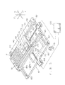
- FIG. 2 is a perspective view of the screening apparatus of FIG. 1 .
- a screening apparatus 1 is an apparatus that illuminates a plurality of microparticles (e.g., living cells) on a measurement chip 60, searches for a predetermined microparticle to be a target sample based on fluorescence emitted from microparticles, selectively sucks microparticles in a well in which a microparticle satisfying collecting conditions is retained to collect them onto a receiving plate 50.
- microparticles e.g., living cells
- the screening apparatus 1 includes a base 11, a supporting section 12 ( FIG. 2 ), a collecting section 13, a measuring section 14, an image analyzing section 15 (analyzing section) and a moving section 16, and, as shown in FIG. 2 , all the sections are covered with a cover 19.
- the cover 19 prevents entry of light and foreign substances from outside.
- the base 11 is a main body frame for holding each component of the screening apparatus 1.
- a direction perpendicular to the plane of paper of FIG. 1 is an X-direction (first direction) and a right and left direction is a Y-direction (second direction).
- Z-direction is a direction perpendicular to the X-direction and the Y-direction.
- the base 11 includes plate members 111, 112 and 113 disposed substantially horizontally, and holds the collecting section 13, the measuring section 14 and the moving section 16 via the plate members.
- the plate members 111 and 112 are secured parallel to each other by a plurality of vertical members 114, and the plate members 112 and 113 are secured parallel to each other by a plurality of members 115.
- This member 115 is made of a material having a vibration shielding property and is adjustable in height.
- the supporting section 12 and a supporting table 30 are secured on the plate member 113, which is located at the top most position among the plurality of plate members.
- the supporting section 12 is disposed upright on the plate member 113 vertically and along Z-direction.
- the supporting table 30 includes leg sections 30a and a support-plate 30b.
- the plate members 111, 112 and 113 and the support-plate 30b are disposed at a predetermined interval between each other in the Z-direction.
- the moving section 16 is mounted and secured on the support-plate 30b of the supporting table 30.
- a mounting table 40, a receiving plate 50 and a measurement chip 60 are mounted on the moving section 16.
- the moving section 16 is capable of moving and positioning the mounting table 40, i.e., the receiving plate 50 and the measurement chip 60, along the X-direction and/or the Y-direction.
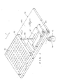
- FIG. 3 is a perspective view showing details of the moving section 16 and the mounting table 40 shown in FIG. 2 .
- the moving section 16 includes a table 161 and a table 162 disposed on the said table.
- the table 161 is secured to the supporting table 30, and the table 162 mounted thereon can be positioned by being moved along the X-direction.
- the mounting table 40 is mounted so as to be capable of being positioned by being moved along the Y-direction.
- Engaging members 165 and 165 each having a U-shaped cross section and a nut 166 are provided on a lower surface of the table 162.
- the engaging members 165 and 165 movably engage with the guide rails 163 and 163, respectively.
- a feed screw 167 of the motor 164 is screwed to the nut 166.
- the motor 164 is electrically connected to a control unit 100. By operating the motor 164 in response to a command from the control unit 100 to rotate the feed screw 167, the table 162 is positioned by being moved along the X-direction.
- Guide rails 168 and 168 and the motor 169 are provided on an upper surface of the table 162.
- Engaging members 170 and 170 each having a U-shaped cross section and a nut 171 are provided on a lower surface of the mounting table 40.
- the engaging members 170 and 170 movably engage with the guide rail 168 and 168, respectively.
- a feed screw 172 of the motor 169 is screwed to the nut 171.
- the motor 164 is electrically connected to the control unit 100. By operating the motor 164 in response to a command from the control unit 100 to rotate the feed screw 172, the mounting table 40 is positioned by being moved along the Y-direction.
- the tables 161 and 162 have openings 174 and 173, respectively, and further, the mounting table 40 includes an opening 175. These openings 173, 174 and 175 have respective sizes that they always overlap with each other even if the table 162 moves in the X-direction and the mounting table 40 moves in the Y-direction. Through these openings 173, 174 and 175, light L from an objective lens 110 side of the measuring section 14 is illuminated on the microparticles on the measurement chip 60 on the mounting table 40.
- FIG. 4 is a perspective view showing a configuration of the receiving plate 50 and a measurement chip 60 on the mounting table 40 shown in FIG. 3 .
- the mounting table 40 is, for example, a rectangular plate-like member.
- the receiving plate 50 and the measurement chip 60 can be detachably mounted on a mounting surface 41 of the mounting table 40 so as to be arranged along the Y-direction.
- the receiving plate 50 is a plate-like member.
- the receiving plate 50 includes a large number of wells 51 arranged in a matrix at a constant interval along the X-direction and the Y-direction.
- the wells 51 are collecting-and-storing sections each capable of, when microparticles such as organism cells are discharged sequentially from a suction-ejection capillary 140, separately collecting and storing microparticles which have been discharged sequentially.
- the well 51 of the receiving plate 50 is a recessed portion having, for example, a substantially U-shaped vertical direction cross section or a recessed portion having a cup-shape.
- the measurement chip 60 is secured to a mounting surface 40a of the mounting table 40 by a securing member 120, and the fixing member 120 is positioned and secured at a predetermined position on the mounting table 40.
- FIG. 5 is an enlarged sectional view showing a configuration of the measurement chip 60 and the securing member 120 of the measurement chip.
- the securing member 120 secures and holds the measurement chip 60 at a position of a reference level CL at a certain level with respect to the mounting surface 41 of the mounting table 40.
- the securing member 120 includes casing sections 121, 122 and an elastic member 123.
- the elastic member 123 is a substantially rectangular ring member, and the elastic member 123 is secured to a flat surface 126 inside the casing section 122.
- the measurement chip 60 is placed between the casing sections 121 and 122, and with the measurement chip 60 being pushed up in the Z1 direction by an elastic member 123, an upper surface 60a of the measurement chip 60 is in pressure contact with a flat inner lower surface 121a of the casing section 121. Further, the inner lower surface 121a of the casing section 121 is provided with a sealing member 128, and the sealing member 128 provides a seal between the reference level CL of the securing member 120 and the upper surface 60a of the measurement chip 60.
- the upper surface 60a of the measurement chip 60 With the upper surface 60a of the measurement chip 60 being pressed against the inner lower surface 121a of the casing section 121, the upper surface 60a of the measurement chip 60 is positioned to the reference level CL. Thereby, even if there is, for example, a thickness variation and warping of the measurement chip 60, it is possible to reduce a decrease in an accuracy of positioning due to an influence of the thickness variation and an influence of the warping. Therefore, a distance in the Z-direction between the upper surface 60a of the measurement chip 60 from an objective lens 110 of the measuring section 14 and the receiving plate 50 can be controlled accurately. In other words, a position of a microparticle M in the well 61 of the measurement chip 60 and the distance between the objective lens 110 of measuring section 14 and the receiving plate 50 can be managed accurately.
- the casing section 121 includes a liquid holding section 129 that retains a liquid A, which is provided at a central part in a direction of its plane and above the measurement chip 60, and is capable of retaining various liquids such as a medium, a reagent, and a reaction liquid.
- the casing section 121 can be opened and closed with respect to the casing section 122 using, for example, a hinge assembly section, not shown. Thereby, the measurement chip 60 in the securing member 120 can be removed and replaced with a new measurement chip 60.
- the measurement chip 60 is made of a translucent material, e.g., glass and plastics, and, a large number of wells 61 are arranged in a matrix in the upper surface 60a thereof.
- each of the wells 61 is a recessed portion having a substantially a trapezoid or a substantially cup-shaped vertical cross section, and a horizontal cross section of the well 61 is preferably substantially circular. It has such a size that a single microparticle M can be stored therein by dispensing or batch-introducing the microparticles M.
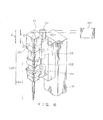
- FIG. 6 is a perspective view showing a configuration of a collecting section 13 shown in FIG. 1
- FIG. 7 is a cross sectional view showing a configuration of the operating section shown in FIG. 6
- the collecting section 13 includes an operating section 130 and a base section 131, and the base section 131 is secured to the supporting section 12.
- the operating section 130 includes an actuator 132 (pump) and a suction-ejection capillary 140.
- the actuator 132 includes an actuator main body 133, and a substantially cylindrical plunger 136 accommodated in a cylinder 134 of the actuator main body 133, and a predetermined fluid is pumped with a reciprocating plunger 136 within the cylinder 134.
- a conduit 135 that provides communication between the cylinder 134 of the actuator main body 133 and the suction-ejection capillary 140 is provided below the actuator 132.
- the suction-ejection capillary 140 includes a flange section 141 that is detachably attached to the conduit 135 and a capillary main body 142 (hereinafter, simply referred to as a "capillary") that is penetrating through the flange section 141 and extending downwardly.
- a ring-shaped elastic member 143 is attached at a connection surface between the flange section 141 and the conduit 135.
- the capillary 142 is a hollow member having a tapered shaped with its diameter decreasing along the Z2 direction (downward direction) and has a conduit formed therethrough.
- a proximal end portion 142a of the capillary 142 is connected to the conduit 135.
- a distal end portion 142b of the capillary 142 is in the vicinity of the well 61 of the measurement chip 60 during the suction of a microparticle.
- the base section 131 includes a motor 151 disposed at an upper end of the base section and a feed screw 152 attached to the motor, and the feed screw 152 is screwed to a nut 137 of the operating section 130.
- the motor 151 is electrically connected to the control unit 100.
- the control unit 100 operates the motor 151 to rotate the feed screw 152 to thereby vertically move and position the operating section 130 together with the nut 137 along the Z-direction (Z1 and Z2 directions).
- the measuring section 14 By illuminating light L onto a region of the measurement chip 60 in which a plurality of wells 61 are provided, the measuring section 14 causes fluorescence to be produced from microparticles M in the region and receives the fluorescence ( FIG. 1 ).
- the fluorescence received from the microparticles M is subjected to an image analysis by an image analyzing section 15.
- the image analyzing section 15 calculates a fluorescence intensity (luminance) of a microparticle M1 emitting fluorescence of at least a maximum luminance from among a plurality of microparticles M in each well 61.
- the control unit 100 detects, in a plane constituted by an X-direction and a Y-direction, a position of the well 61 in which the microparticle M1 emitting fluorescence of a maximum luminance satisfying the collecting conditions is contained. Then, by supplying a control driving signal to the motors 164 and 169 of FIG. 3 , the control unit 100 can position the well 61 of the measurement chip 60 on the moving section 16 directly beneath the suction-ejection capillary 140. That is, the suction-ejection capillary 140 is configured to be capable of targeting a particular well and sucking a microparticle in the well.
- the suction-ejection capillary 140 can suck, from a selected well among a plurality of wells, in other words, from a well containing a microparticle satisfying predetermined collecting conditions, at least one microparticle. Further, the suction-ejection capillary 140 can eject the selected at least one microparticle into a predetermined well 51 in the receiving plate 50.
- the measuring section 14 By illuminating the measurement chip 60 and microparticles M retained in the measurement chip 60 with light guided from at least one light source, the measuring section 14 acquires shape and position information obtained from transmitted light, reflected light or fluorescence, and luminance information such as chemiluminescence with a resolution finer than an average size of the microparticles, and also acquires information such as a shape of the measurement chip itself or a positional coordinate or a size of the well 61 disposed in the measurement chip 60.
- the image analyzing section 15 acquires data for confirming that a microparticle M1 satisfying an luminance condition which can be set by the observer exists at least in each well 61.
- the image analyzing section 15 extracts optical information from the microparticles by matching and verifying the positional coordinate information of the well 61 from the transmitted light or the reflected light, and the optical information of fluorescence and chemiluminescence.
- the measuring section 14 has an autofocus function.
- the measuring section 14 is capable of performing measurement while being focused at a predetermined position and determining a positional relationship between the distal end portion 142b of the suction-ejection capillary 140 and an upper surface of the measurement chip 60 by performing an autofocus on both of them.
- the measuring section 14 has an objective lens 110, and the objective lens 110 guides light to the measurement chip 60.
- the objective lens 110 is disposed below the measurement chip 60 and the moving section 16, and the suction-ejection capillary 140 is disposed above the measurement chip 90 and the moving section 16. Accordingly, the measurement chip 90 and the moving section 16 thereof can be disposed between the objective lens 110 and the suction-ejection capillary 140.
- a pump light source 181 includes, for example, a laser source and a mercury lamp.
- a shutter unit 182 is disposed between the pump light source 181 and a fluorescence filter unit 183.
- the shutter unit 182 is capable of blocking light L produced by the pump light source 181 directly in front of the fluorescence filter unit 183 in a case where the light L is not illuminated on the microparticles M on the measurement chip 60.
- the measuring section 14 includes the pump light source 181 as a light source, the fluorescence filter unit 183 comprising an optical filter (pump filter) 184 for selecting only a desired pump wavelength band among light illuminated from the pump light source 181, an optical filter (fluorescence filter) 185 for selecting only a desired wavelength band of the optical information from the measurement chip 60, and a dichroic mirror 186 for changing an optical path length in accordance with a difference between wavelength bands of the pump light and the optical information.
- the fluorescence filter unit 183 comprising an optical filter (pump filter) 184 for selecting only a desired pump wavelength band among light illuminated from the pump light source 181, an optical filter (fluorescence filter) 185 for selecting only a desired wavelength band of the optical information from the measurement chip 60, and a dichroic mirror 186 for changing an optical path length in accordance with a difference between wavelength bands of the pump light and the optical information.
- the measuring section 14 has the objective lens 110 for guiding light emitted from the pump light source 181 to the measurement chip 60 and for collecting optical information obtained from the measurement chip 60, a focus unit 187 having an automatic focus function capable of moving the objective lens 110 in an optical axis direction, and a light receiving section 188 as an optical information from a measurement object.
- the fluorescence filter unit 183 and the light receiving part 188 are fixed to an epifluorescence unit 190.
- the measuring section 14 includes a half mirror, not shown.
- a half mirror By switching between the half mirror and the fluorescence filter unit 183, a part of the light from the pump light source 181 is irradiated on an observation target, and at the same time, a part of the reflected light from the observation target is guided to a light receive part 188. Thereby, shape and position information of the upper surface 60a of measurement chip 60 and the well 61 formed on the upper surface can be measured.
- an objective lens of a required magnification can be positioned at a position below the measurement chip 60.
- the motor 189 By operating the motor 189 in accordance with, for example, a command from the control unit 100, the objective lens 110, for example, located at a position below the measurement chip 60 is moved and positioned along the Z-direction, the focus unit 187 can perform focus adjustment of the objective lens 110 on microparticles M in the measurement chip 60.
- the present inventors focused their attention on the capillary 142 and the measurement chip 60, and particularly on their positional relationship and sizes during the suction, and found that the collecting section 13 can accurately suck the microparticles M on the measurement chip 60.
- the collecting section 13 can accurately suck the microparticles M on the measurement chip 60.
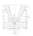
- FIG. 8 is a cross sectional view showing a positional relationship between the capillary 142 and the well 61 during suction of a microparticle.
- the distal end portion 142b of the capillary 142 has a substantially annular cross section and has an end surface 144.
- An outer dimension of the distal end of the capillary 142 is designed to be greater than a width of the well 61 formed in the measurement chip 60.
- the distance between the central axis C1 of the capillary 142 and the central axis C2 of the well 61 is ⁇ ( ⁇ 0).
- a flow path P1 and a flow path P2 longer than the flow path P1 are formed between the end surface 144 and the upper surface 60a.
- the distance L between the capillary 142 and the well 61 is smaller than a diameter of the microparticle M (2Rc) (conditional expression (1)).
- a value obtained by subtracting the inner peripheral radius Ri of the capillary 142 from the an outer peripheral radius Ro is greater than a half of the distance L (conditional expression (2)), and further, a value obtained by subtracting the aperture radius of the well 61 from the outer peripheral radius Ro of the capillary 142 is greater than a half of the distance L (conditional expression (3)).
- the distance ⁇ between the central axis C1 and the central axis C2 is, for example, about 0.1 times to 1 time of the aperture radius Rw of the well 61. With such a configuration, the upward one way flow F3 can be produced easily. Also, it is more preferable that the distance ⁇ is about 0.2 times to 0.4 times the aperture radius Rw of the well 61. Thereby, the microparticle M can be smoothly collected with the capillary 142.
- the inner peripheral radius Ri of the capillary is about 0.8 times to 2 times the aperture radius Rw of the well 61.
- the suction operation by the capillary 142 in addition to defining the positional relationship and dimensions described above in the suction, it is more effective to perform a pre-suction operation which sucks a specific amount of liquid A before sucking a microparticle M.
- the suction control including this pre-suction operation is performed by the collecting section 13 and the control unit 100.
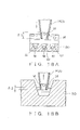
- the distal end portion 142b of the capillary 142 is inserted into the liquid A retained on the measurement chip 60 ( FIG. 10A ). Then, when the distal end portion 142b is inserted into the liquid A to a predetermined depth to such an extent that it does not influence the liquid in the well 61, a pre-suction operation is performed for a predetermined period of time. At this time, a specific amount of liquid A enters into an inner space E of the capillary 142, and a liquid layer A1 is formed in the distal end portion 142b of the capillary 142 ( FIG. 10B ). Thereafter, the capillary 142 is made to approach the measurement chip 60 to such a position where the distance is L as described above ( FIG.
- d1 be a depth of the liquid layer A1 and d2 be a depth of the liquid layer A1+A2
- d2 be a depth of the liquid layer A1+A2
- the following conditional expression is satisfied.
- the aforementioned d1 is 0.3 mm and d2 is 2.7 mm. Therefore, an amount of liquid of the liquid layer A1 formed by the pre-suction operation is 0.3 ⁇ l, and an amount of liquid of the liquid layer A2 formed by a subsequent suction operation (microparticle suction operation) is 0.7 ⁇ l.
- the liquid layer A1 is formed within the capillary 142 before the capillary 142 arrives at a position to start suction of a microparticle M.
- the microparticle M will not be placed at a liquid surface in the capillary 142, and the liquid layer A1 will be placed upwardly of the microparticle M.
- the microparticle M does not remain in the capillary 142. Specifically, a phenomenon such as the microparticle M remains by being attached to an inner wall of the capillary 142 is prevented, and an ejection accuracy of the microparticle M improves.
- the capillary 142 may suck from any another container containing any liquid, and this liquid may be different from the liquid A.
- this liquid may be different from the liquid A.
- step S1 location information of the measurement chip 60 is acquired from information regarding a reference position of the measurement chip and correction parameters or the like (step S1). Thereafter, an image analysis is performed to acquire center position coordinate information of each well (step S2). Then, a light is illuminated to acquire optical information of a microparticle (sample) and a luminance analysis is carried out (step S3).
- the luminance analysis may be performed by, for example, as shown in FIG. 12D described later, introducing a reaction liquid into each of the wells to cause the microparticles in the well to produce fluorescence, and measuring a temporal variation of this fluorescence information. Also, as shown in FIGS. 15A and 15B described later, the microparticles stored in each well on the measurement chip 60 may be counted.
- collecting conditions may be set as collecting conditions of a microparticle required by a user, for example, conditions in which a luminance of a certain fluorescence has exceeded a predetermined threshold, or a condition in which, when a plurality of fluorescence (e.g., colors of the fluorescence are different) are used, a luminance of at least one of the fluorescence has exceeded a predetermined threshold, or any combination thereof.
- a plurality of fluorescence e.g., colors of the fluorescence are different
- step S4 Some conditions determined in a manner described above are input (step S4), and a microparticle that satisfies the aforementioned collecting conditions is identified as a target sample (step S5). Then, a center position of the capillary is acquired by an image analysis, and a position shifted towards the center position by a distance ⁇ is set as a center position of the well during the collecting of the microparticle (position information) (step S6). The center position of each of the wells in which a target sample is contained is moved to match the center position of the well during the collecting of the microparticle, which is set in step S6, and target samples identified in step S5 are collected sequentially (step S7). The collected sample is placed in a predetermined well in the receiving plate 50 which was set in advance by the user.
- an outer dimension of the distal end of the capillary 142 is greater than a width of the well 60 formed in the measurement chip 60, and the capillary 142 sucks a microparticle M at a position where an interval between the distal end portion 142b and the measurement chip 60 is distance L and the central axis C1 of the distal end portion 142 and the central axis C2 of the well 61 are at positions displaced from each other.
- a microparticle M can be accurately sucked and collected on a cell-by-cell basis.
- a microparticle M which is a target sample, can be accurately sucked without being influenced by a fluid resistance produced in the liquid A in the well 61. Further, with the aforementioned configuration, a single microparticle M which is a target sample can be accurately sucked and collected, and a process can be performed on a cell-by-cell basis.
- the screening apparatus of the present embodiment includes the screening apparatus of the first embodiment and additionally a mechanism of introducing a liquid into a liquid holding section and discharging the liquid from the liquid holding section. It is to be noted that the second embodiment does not necessarily include the configuration of the screening apparatus of the first embodiment, and may be implement independently, without depending on the configuration of the first embodiment.
- a casing section 221 has a liquid holding section 229 that retains the liquid A and provided at a central portion in a direction of the plane and above the measurement chip 60, and thus it is configured to retain various liquids such as a medium, a reagent, and a reaction liquid.
- This liquid holding section 229 is a space defined by an inner side surface 221a of the casing section 221 and the upper surface 60a of the measurement chip 60.
- a liquid introducing section 230 and a liquid discharging section 231 are provided in the vicinity of one end and in the vicinity of the other end, respectively, of an upper part of the liquid holding section 229.
- the liquid introducing section 230 introduces a predetermined liquid into the liquid holding section 229, and the liquid discharging section 231 discharges the predetermined liquid held in the liquid holding section 229.
- the liquid introducing section 230 and the liquid discharging section 231 are configured to be able to perform discharging and introducing operations at the same time.
- a reaction liquid H is introduced into the liquid holding section 229 by the liquid introducing section 230 while discharging the medium G to the outside by the liquid discharging section 231.
- the medium G which has been held in the liquid holding section 229 is replaced with the reaction liquid H.
- the present method by causing the reaction of the microparticle M and measuring fluorescence from the microparticle M, it is found that an intensity stronger than that of the microparticle which does not react is obtained ( FIG. 12D ).
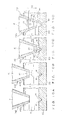
- a dropping section 232 may be provided which drops a liquid such as a reagent as a drop I1 for each well in a state where a predetermined amount of medium G has been discharged outside until a liquid surface level of the medium G comes to or to the vicinity of an upper surface of the measurement chip ( FIG. 12B ), or a spraying section 233 may be provided which sprays a liquid such as a reagent as mist I2 to a predetermined region including a plurality of wells in a state where a predetermined amount of discharged medium G is discharged outside until a liquid surface level of the medium G comes to an upper surface of the measurement chip ( FIG. 12C ).
- a spraying section 233 When the spraying section 233 is placed as shown in FIG.
- a mist amount of the mist I2 is greater for a well nearer the casing section 221, and a mist amount of the mist I2 becomes less as it becomes farther from the casing section 221.
- a concentration of mist I2 introduced into each well can be made to vary by changing a position at which the spraying section 233 is attached with respect to the measurement chip 60.
- the image analyzing section 15 may continuously measure the temporal variation and, based on the result of a measurement, identify the well for which a sample is to be collected. For example, with temporal variation data of the fluorescence intensity, a difference value between its peak value and a base value to be described later is compared with an arbitrary threshold, and a sample having a peak value exceeding the threshold can be determined as a collecting target, or alternatively, the sample having a peak exceeding the threshold can be excluded from a collecting target. Thereby, collecting can be performed by selecting whether or not there is a reaction of the microparticle.
- the base value is defined by, for example, (i) a minimum value during the measurement, (ii) an average until a specified measurement time (i.e., an average value of values before introduction of a liquid), (iii) an average of values when a certain reaction liquid is introduced (e.g., an average value of value when a liquid which should not react is flowed), and (iv) zero (in this case, only the peak is used).
- a moving average can be taken, and in order to determine a significant difference, based on a standard deviation ⁇ , a difference that is less than or equal to a specified criterion may be excluded.
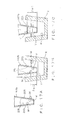
- a critical position where the medium G can be discharged by the liquid discharging section 231 is the upper surface 60a of the measurement chip 60, and, in practice, the medium G slightly remains. Even in this state, as shown in FIG. 13A , by dropping a liquid such as a reagent as a liquid drop I1 towards the center of the well 61 containing a microparticle M (cell) therein, since the vicinity of the microparticle M is substantially filled with an intended reagent, the microparticle can be reacted.
- reaction can be performed while completely isolating the wells.
- the screening apparatus 1 is provided with the dropping section 232 and the spraying section 233.
- a dropping process and a spraying process may be performed outside the apparatus without providing a dropping section and a spraying section in the screening apparatus 1.
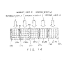
- partitioning sections 235 which divides a planar region of the liquid holding section 229 into five regions 234a to 234e may be provided as shown in FIG. 14 .
- a liquid of any kind can be introduced into each region and cause the microparticle to react.
- a liquid introducing section/liquid discharging section may be provided in each region, or may be provided in a part of a plurality of regions.
- the present embodiment employs a method in which, firstly, a single microparticle M is placed in the well 61, and then a liquid is introduced into the well to cause reaction of a microparticle M. To the contrary to this method, it is also possible to firstly cause the microparticle M to react and thereafter place a single microparticle M in the well 61.
- a liquid containing a large amount of cells m as the microparticles M is placed into a container 240, and thereafter, a high-concentration liquid K1 containing a substance to be reacted k such as an antibody, a chemical compound or the like is placed into the container 240, and, reaction is waited for a predetermined time. At this time, some of the cells m reacts with the substance to be reacted k and become reacted cells m1 (in FIG. 15A , two cells react).
- a liquid K2 such as a specific amount of medium is placed into the container 240, and reaction is waited again for a predetermined time. Then, a predetermined cell m which did not react with the first high concentration reacts and becomes a reacted cell m1 (in FIG. 15A , one cell newly reacts). Thereafter, an operation of adding the liquid K2 is repeated to gradually reduce the concentration the substance to be reacted k, and the predetermined cell m is reacted at each concentration (in FIG. 15A , six cells m finally reacts).
- a liquid in the container 240 is introduced into the liquid holding section 229 and each cell is received in the well 61. Then, the reacted cell m1 is sucked and collected cell-by-cell with the capillary 140 of the suction-ejection capillary 140, and the collected reacted cell m1 is cultured and analyzed. According to this method, suction and collecting on a cell-by-cell basis can be achieved and also detection accuracy can be improved irrespective of the reaction characteristic of the cell.
- the concentration of the substance to be reacted k in the container 240 may be gradually increased.
- the reagent used in the reaction is not limited to only one kind, and may be a plurality of reagents.
- the cell to be reacted is not limited to only one kind, and may be a plurality of kinds.
- the measuring section 14 acquires the position information of the microparticle by a transmitted light, a reflected light or the fluorescence on a cell-by-cell basis.
- a transmitted light a reflected light
- the fluorescence the fluorescence on a cell-by-cell basis.
- even if a single microparticle is retained in a single well since there is a variation in the size of the microparticles, when the target sample is a microparticle having a smaller size than that of the well, it is unclear as to which position in the depth direction of the well the microparticle is placed and thus measurement cannot be performed accurately.
- the measuring section 14 detects a surface position of the measurement chip 60 based on optical information about the measurement chip which is obtained by illuminating the measurement chip 60. Based on a particle size of the microparticle M which is a target sample and a dimension of the well, the measuring section 14 corrects a focus position of the light illuminated on the microparticle M in a depth direction (a thickness direction of the measurement chip 60) by a predetermined amount (3D measurement). Specifically, the image analyzing section 15 calculates the center position of the microparticle based on the surface position of the measurement chip 60 and the size of the microparticle M.
- the measuring section 14 illuminates at a substantially central position of the microparticle M retained in the well 61.
- the upper surface 60a of the measurement chip 60 is taken as a reference surface position ( ⁇ 0) and the focal point of the light illuminated is changed to a position of -10 ⁇ m, which is approximately a radius of the microparticle, from the reference surface position.
- the depth of the well is approximately 50 % to 100 % of the outer diameter of the well, and more preferably 70 % to 80 % of the well, a single microparticle can be appropriately retained and collected in a single well.
- the outer diameter of the microparticle is approximately 50 % to 80 % of the outer diameter of the well.
- a center position of the microparticle is calculated based on a shape of the well 61 and the dimension of the microparticle M, and a measurement result of a high accuracy can be obtained by focusing on a calculated position. For example, when a dimensional relationship between the well 61 and the microparticle M is as shown in FIG. 16 , a measurement result of a highest accuracy can be obtained by focusing on a position at -10 ⁇ m shown in FIG. 16 .
- a focus position between +10 ⁇ m and -20 ⁇ m to cover from the bottom part of the well to a surface part of the measurement chip at an interval of the same extent as the radius of the microparticle, for example, at a 10 ⁇ m interval in FIG. 16 .
- a focus position between +10 ⁇ m and -20 ⁇ m to cover from the bottom part of the well to a surface part of the measurement chip at an interval of the same extent as the radius of the microparticle, for example, at a 10 ⁇ m interval in FIG. 16 .
- the number of microparticles existing in one well can be counted.
- the well 51 in the receiving plate 50 may be used as a rinsing reservoir, or a rinsing reservoir provided separate from the well may be used.
- FIG. 17A when a suction-ejection operation is performed, there may be a case where a microparticle M attaches to an inner wall 251 and/or an outer wall 253 of the distal end portion 142b. Accordingly, by inserting the distal end portion 142b of the capillary 142 into a rinsing liquid Y contained in the rinsing reservoir X ( FIG. 17B ), the microparticle attached to an outer wall 253 of the capillary 142 can be removed. Also, by sucking and ejecting the rinsing liquid ( FIG. 17C ), the microparticle attached to the inner wall 251 of the capillary 142 can be removed.
- a liquid depth in the suction operation is defined as ⁇ 1 (corresponds to depth d2 in FIG. 10D ), and a depth of a part of the capillary 142 that is submerged under a liquid surface in the receiving plate 50 during the ejection operation is defined as ⁇ 2.
- a depth ⁇ w2 of a part of the capillary 142 that is submerged under a liquid surface in the rinsing reservoir is set so as to be greater than the depth ⁇ 2 in the ejection operation ( ⁇ w2> ⁇ 2).
- a sucked amount ⁇ w1 of the rinsing liquid is set so as to be greater than the depth of liquid ⁇ 1 during the suction operation (bw1> ⁇ 1).
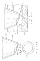
- FIGS. 19A to 19C are diagrams showing variations of the distal end portion 142b of the capillary 142.
- the inner wall 251 of the distal end portion 142 is provided with a hydrophobic layer 252 (hydrophobized surface) and the outer wall 253 is provided with a hydrophobic layer 254.
- These hydrophobic layers 252 and 254 are formed by, for example, coating a silicone-based material.
- the inner wall 251 and the outer wall 253 of the distal end portion 142b may be provided with hydrophilic films 255, 256, respectively (see FIG. 19B ).
- the hydrophilic films 255 and 256 are formed with a hydrophilic coating by plasma treatment, for example.
- a microparticle M such as a cell is less likely to attach to the inner wall 251 and/or to the outer wall 253, an ejection accuracy of microparticle M can be improved.
- a distal end side of the inner wall 251 of the distal end portion 142b may be provided with a hydrophilic film 257 and a hydrophobic layer 258 may be provided at an upper part of the hydrophilic process film 257.
- the distal end side of an inner portion of the capillary 142 is subjected to a hydrophilic treatment and a portion nearer to the proximal end is subjected to a hydrophobic treatment, the microparticle M is less likely to move further towards the proximal end of the capillary 142 during the suction and the microparticle M is less likely to remain in the capillary.
- the suction-ejection accuracy can be improved.
- a variant of the collecting section 13 will described with reference to FIGS. 20 and 21 .
- the collecting section of the present variant is a mechanism for improving a collecting accuracy in a subsequent suction operation by releasing a residual pressure in the capillary 142 in a current suction operation. Since the configuration of the present variant is the basically same as the collecting section 13, different parts will be described below.
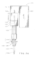
- a collecting section 330 includes a branch path 332 provided at a cylinder 331 of the actuator main body 133, a conduit 333 connected to the branch path 332 and made of an elastic material such as a rubber tube, a solenoid valve 334 (valve section) connected to the conduit, and a dust filter 335 disposed at an opening side of the solenoid valve 334.
- An inner diameter of the conduit 333 is greater than an inner diameter of the end surface 144 of the capillary 142, and an inner diameter of a channel in the solenoid valve 334 is greater than the inner diameter of the end surface 144 of the capillary 142.
- this collecting section 330 An operation of this collecting section 330 will be described with reference to FIG. 21A . Firstly, with an upward movement of the plunger 136, a liquid containing a microparticle M which is a target sample is sucked by the capillary 142. At this time, since the solenoid valve 334 is closed, an air flow in the branch path 332 does not occur.
- the plunger 136 moves downwardly and discharges the liquid containing the target sample M from the capillary 142 ( FIG. 21B ). At this time, the plunger 136 operates with a displacement greater than a displacement moved through during the suction operation. By this operation, the microparticle M or an entirety of the liquid in the capillary 142 is ejected. Also during this ejection operation, since the solenoid valve 334 is closed, an air flow in the branch path 332 does not occur.
- the solenoid valve 334 is firstly opened, and the plunger 136 is moved upward with the solenoid valve 334 being open ( FIG. 21C ).
- the dust filter 335 has an open end, and the inner diameter of the conduit 333 and the inner diameter of the flow path in the solenoid valve 334 are greater than the inner diameter at the end surface 144 of the capillary 142, an air flow that is flowing inwardly is produced in the branch path 332 and thus a residual pressure in the capillary 142 is released.
- the microparticle M or an entirely of the liquid in the capillary 142 is ejected during the ejection operation and the residual pressure in the capillary 142 is released in the subsequent suction operation, a collecting accuracy can be further improved.
- the solenoid valve 334 may be provided with a pump 336 and air may be forcedly blown into the branch path 332 when returning the plunger 136 to the position prior to the suction operation ( FIG. 20 ). Thereby, the collecting accuracy can be further improved.
- FIGS. 22 and 23 are diagrams showing a variant of the distal end shape of the capillary 142.
- the shape of the distal end portion 142b of the capillary 142 can be configured as follows.
- a distal end portion 342b of the capillary 342 has an end surface 344 that forms a predetermined angle ⁇ (0° ⁇ ⁇ ⁇ 90°) with respect to a horizontal direction.
- a distal end section 442b of a capillary 442 has a helical end surface 444 and a stepped portion 445.
- the end surface 444 is an inclined surface that is inclined with respect to the upper surface 60a of the measurement chip 60, and the stepped portion 445 is formed in the inclined surface.
- a helical vortex is produced in the vicinity of the end surface 444, and liquid flows F1 and F2 having flow rates largely differing from each other can be produced.
- the upward one way flow F3e can be positively produced in the well 61, and an accurate suction of the microparticle M can be achieved.
- FIG. 24 is a perspective view showing a variant of the collecting section 13 of FIG. 7
- FIG. 25 is a diagram for explaining, in parts (a) to (d), an operation of the collecting section of FIG. 24 .
- the collecting section in this variant has a detecting section and a vertical movement stage to be described below in addition to the configuration of the collecting section 130 of FIG. 7 . Note that the same numerals are used for the same configuration as the collecting section 130 and explanation thereof is omitted.
- a collecting section 450 includes a detecting section 451 (detecting mechanism) that is disposed above the actuator 132 and detects a load on the suction-ejection capillary 140 and a vertical movement stage 452 (moving mechanism) that moves the suction-ejection capillary 140 in a vertical direction.
- the detecting section 451 is, for example, a pressure sensor, and detects a pressure on the measurement chip 60 from the suction-ejection capillary 140.
- the control unit 100 determines whether or not the distal end portion 142b of the capillary 142 and the upper surface 60a of and the measurement chip 60 are in contact, and transmits a signal corresponding to a determination result to the vertical movement stage 452.
- the vertical movement stage 452 moves the suction-ejection capillary 140 in a vertical direction in response to the signal from the control unit 100 by driving a motor, not shown.
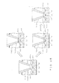
- the collecting section 450 of the present variant operates as follows. As shown in FIG. 25 , in parts (a) to (d), the control unit 100 receives a signal from the detecting section 451 and determines whether or not the end surface 144 of the suction-ejection the capillary 142 is in contact with the upper surface 60a of the measurement chip 60. In a case where pressure detected by the detecting section 451 is zero, the control unit 100 determines that the end surface 144 is not in contact with the upper surface 60a, and the suction operation of the microparticle M is performed (part (b) in FIG. 25 ).
- the control unit 100 determines that the end surface 144 of the suction-ejection capillary 142 and the upper surface 60a of the measurement chip 60 are in contact (part (c) in FIG. 25 ) and moves the vertical movement stage 452 upwardly move the suction-ejection capillary 140 by a predetermined distance (part (d) in FIG. 25 ). Thereafter, the suction operation of the microparticle M is performed at a position after the adjustment.
- the suction-ejection capillary 142 and the measurement chip 60 are in contact, since they are spaced apart, it is possible to positively prevent a state in which the microparticle M cannot be sucked by the suction-ejection capillary 142. Since the state in which suction is not possible can be positively avoided, the distance L between the end surface 144 of the suction-ejection capillary 142 and the upper surface 60a of the measurement chip 60 can be made as small as possible, and it is possible to positively suck only the microparticle M which is a target sample.
- the distal end portion 142b of the capillary 142 has a substantially cylindrical shape, it may also have a substantially square tubular shape.
- the well 61 has a horizontal sectional shape which is generally circular, it may also be generally rectangular.
- a horizontal sectional shape of the distal end portion of the capillary may be nonsimilar or have a different shape from the horizontal sectional shape of the well.
- a horizontal sectional shape of the distal end of the capillary is generally circular, and a horizontal sectional shape of the well may be generally rectangular.
Landscapes
- Chemical & Material Sciences (AREA)
- Health & Medical Sciences (AREA)
- Physics & Mathematics (AREA)
- General Health & Medical Sciences (AREA)
- Immunology (AREA)
- Life Sciences & Earth Sciences (AREA)
- Analytical Chemistry (AREA)
- Biochemistry (AREA)
- Pathology (AREA)
- General Physics & Mathematics (AREA)
- Chemical Kinetics & Catalysis (AREA)
- Engineering & Computer Science (AREA)
- Clinical Laboratory Science (AREA)
- Signal Processing (AREA)
- Dispersion Chemistry (AREA)
- Plasma & Fusion (AREA)
- Investigating, Analyzing Materials By Fluorescence Or Luminescence (AREA)
- Computer Vision & Pattern Recognition (AREA)
- Investigating Or Analysing Biological Materials (AREA)
Abstract
Description
- The present disclosure relates to a screening apparatus and a screening method for illuminating microparticle, such as cells, detecting a microparticle to be a target sample based on fluorescence emitted from the microparticle, and selectively sucking and collecting the relevant microparticle.
- In the related art, microparticle screening apparatuses are widely used as apparatuses for identifying and sorting microscopic samples, such as cells, in research and testing in the medical field. Recently, in research and testing organizations, there is a need for obtaining identifying and sorting processes of the samples without fracture and for increasing efficiency of research and testing by performing those processes more accurately. Particularly, in a certain field, due to an increasing need for performing the identifying and sorting on a cell-by-cell basis, there is also a need for increasing accuracy and efficiency in the identifying and sorting processes on a cell-by-cell basis.
-
FIGS. 26A and 26B are diagrams for explaining an operation of a screening apparatus of the related art.FIGS. 26A and 26B show an example in which all microparticles, including a microparticle M (target sample) emitting fluorescence of a maximum luminance, are sucked from a well 501 in ameasurement plate 500 and collected into awell 508 of a receivingplate 507. - In the screening apparatus of
FIG. 26A , when asuction pump 504 operates in response to a command from acontrol unit 503, a suction-ejection capillary 505 sucks all microparticles MS, including a microparticle M emitting fluorescence of a maximum luminance, from awell 501, selectively and being distinguished from microparticles in another well 501. Thereafter, the suction-ejection capillary 505 ascends in a Z1-direction and descends in a Z2-direction to place adistal end portion 506 of the suction-ejection capillary 505 into a liquid A' in thewell 508 of thereceiving plate 507 and to discharge all the microparticles MS into the well 508 (FIG. 26B ). In other words, all the microparticle MS can be collected from thewell 501 of themeasurement plate 500 with a movement operation of themeasurement plate 500 in X- and Y-directions and a vertical movement operation of the suction-ejection capillary 505 in a Z-direction by a collecting section. As a result, the microparticle M which is a target sample can be detected from among a large number of microparticles and selectively collected. - Patent Document 1: Japanese Laid-Open Patent Publication No.
2008-249679 - The aforementioned configuration of the related art has disadvantages described below. In a case where a large number of wells are arranged on a measurement plate, it is possible to prevent malfunctioning such as suction of a sample from a well other than the well containing a target sample. However, it merely selectively sucks all microparticles in a well containing a microparticle satisfying collecting conditions as suction target objects, and it is extremely difficult to accurately suck and collect a target sample on a cell-by-cell basis.
- Further, with a shape of a distal end portion of the suction-ejection capillary and a shape of the well, or a positional relationship between them as shown in
FIGS. 26A and 26B , there is a possibility that, during a suction operation, a single cell which is a target sample cannot be sucked accurately due to an influence of fluid resistance produced in the liquid in the well. - It is an object of the present disclosure to provide a screening apparatus and a screening method that can accurately suck and collect a microparticle such as a cell that becomes the target sample.
- In order to solve the aforementioned problem, according to an aspect of the disclosure, a screening apparatus that searches for a predetermined microparticle based on optical information emitted from microparticles to selectively pick up the microparticle searched for is a screening apparatus including a measurement chip that is made of a light permeable material, the measurement chip having a well formed therein that retains a liquid including at least one microparticle, a measuring section that acquires optical information associated with the microparticles, the optical information being obtained by illuminating the microparticles retained in the measurement chip, an analyzing section that analyzes the optical information to extract optical information associated with the microparticles retained in the well, a receiving plate that receives a microparticle selectively picked-up from the measurement chip based on a result of the analysis, a moving section that is capable of moving the measurement chip and the receiving plate with respect to the measuring section, and a collecting section having a pump and a suction-ejection capillary, the collecting section being for collecting a microparticle in the well provided in the measurement chip, the microparticle being sucked by the suction-ejection capillary and ejected at a predetermined position on the receiving plate. An outer dimension of a distal end of the suction-ejection capillary is greater than a width of the well formed in the measurement chip. The suction-ejection capillary sucks the microparticle which is a target sample at a position where the distal end of the suction-ejection capillary and the measurement chip are spaced apart by a predetermined distance and a central axis of the distal end of the suction-ejection capillary and a central axis of the well are displaced from each other.
- Further, the screening apparatus includes a discharging section that discharges a liquid on the measurement chip, and an introducing section that introduces a predetermined liquid onto the measurement chip. A liquid on the measurement chip is replaced by discharging a liquid on the measurement chip by the discharging section and introducing a predetermined liquid by the introducing section.
- Further, with a liquid being discharged by a predetermined amount until reaching an upper surface of the measurement chip or vicinity thereof, an arbitrary reagent may be dropped into each well.
- Further, with a liquid being discharged by a predetermined amount until reaching an upper surface of the measurement chip or vicinity thereof, an arbitrary reagent may be sprayed on a predetermined region of the measurement chip.
- Further, at least one partitioning portion may provided on an upper surface of the measurement chip, and a plurality of set of the discharging section and the introducing section may be provided for each of at least two regions divided by the partitioning portion.
- Further, the microparticle may be contained in a single container before being retained on the measurement chip, wherein a reactant that reacts with the microparticle is added into the container for several times with a concentration of the reactant being gradually changed, and wherein a liquid in the container that contains the microparticle reacted with the reactant is introduced onto the measurement chip.
- The measuring section detects a surface position of the measurement chip based on optical information related to the measurement chip which is obtained by illuminating the measurement chip, the analyzing section calculates a center position of the microparticle from the surface position and a size of the microparticle, and the measuring section illuminates a substantially center position of the microparticle retained in the well based on the center position.
- Preferably, each of the wells retains one each of the microparticles, and wherein the analyzing section analyzes optical information from a single microparticle retained in each well.
- The analyzing section may analyze optical information from at least one microparticle retained in each well and identifies a number of microparticles retained in each well.
- Preferably, the collecting section rinses a distal end of the suction-ejection capillary before suction of the microparticle.
- Preferably, a hydrophobic process surface is formed at least on an inner surface of an end portion of the suction-ejection capillary.
- Further, the pump may include a tubular pump body and a plunger that is movable in a vertical direction within the pump body, and wherein the pump body includes a cylinder provided in communication with a conduit of the suction-ejection capillary and through which the plunger is movable, and a branched path provided in the cylinder.
- Further, it is preferable that a valve section is connected to the branch path via a conduit, and an inner diameter of the valve section and the conduit is greater than an inner diameter of the suction-ejection capillary.
- Further, it is preferable that, after the suction operation of the pump, the valve section is opened to release a residual pressure in the suction-ejection capillary.
- Further, it is preferable that a displacement of the plunger at the time of ejecting the microparticle is greater than a displacement of the plunger at the time of suction of the microparticle.
- Further, it is preferable that the suction-ejection capillary sucks a liquid of a predetermined amount before sucking the microparticle, and thereafter sucks the microparticle.
- The collecting section further includes a detecting mechanism that detects a contact between a distal end of the suction-ejection capillary and an upper surface of the measurement chip, and a moving mechanism that adjusts a distance between the distal end of the suction-ejection capillary and an upper surface of the measurement chip, and in a case where the suction-ejection capillary is in contact with the measurement chip, the suction-ejection capillary is moved to a position where the end surface of the suction-ejection capillary and the upper surface of the measurement chip are at a predetermined distance.
- Further, in order to achieve the above object, a screening apparatus that searches for a predetermined microparticle based on optical information emitted from microparticles to selectively pick up the microparticle searched for is a screening apparatus including a measurement chip that is made of a light permeable material, the measurement chip having a well formed therein that retains a liquid including at least one microparticle, a measuring section that acquires optical information associated with the microparticles, the optical information being obtained by illuminating the microparticles retained in the measurement chip, an analyzing section that analyzes the optical information to extract optical information associated with the microparticles retained in the well, a receiving plate that receives a microparticle selectively picked up from the measurement chip based on a result of the analysis, a moving section that is capable of moving the measurement chip and the receiving plate with respect to the measuring section, and a collecting section having a pump and a suction-ejection capillary, the collecting section being for collecting a microparticle in the well provided in the measurement chip, the microparticle being sucked by the suction-ejection capillary and ejected at a predetermined position on the receiving plate. An outer dimension of a distal end of the suction-ejection capillary is greater than a width of the well formed in the measurement chip. A distal end surface of the suction-ejection capillary is an inclined surface that is inclined with respect to an upper surface of the measurement chip. The suction-ejection capillary sucks the microparticle which is a target sample at a position where the distal end of the suction-ejection capillary and the measurement chip are spaced apart by a predetermined distance.
- Further, in order to achieve the above objects, a screening apparatus that searches for a predetermined microparticle based on optical information emitted from microparticles to selectively pick up the microparticle searched for is a screening apparatus including a measurement chip that is made of a light permeable material, the measurement chip having a well formed therein that retains a liquid including at least one microparticle, a measuring section that acquires optical information associated with the microparticles, the optical information being obtained by illuminating the microparticles retained in the measurement chip, an analyzing section that analyzes the optical information to extract optical information associated with the microparticles retained in the well, a receiving plate that receives a microparticle selectively picked up from the measurement chip based on a result of the analysis, a moving section that is capable of moving the measurement chip and the receiving plate with respect to the measuring section, and a collecting section having a pump and a suction-ejection capillary, the collecting section being for collecting a microparticle in the well provided in the measurement chip, the microparticle being sucked by the suction-ejection capillary and ejected at a predetermined position on the receiving plate. An outer dimension of a distal end of the suction-ejection capillary is greater than a width of the well formed in the measurement chip. A horizontal sectional shape at a distal end portion of the suction-ejection capillary is nonsimilar to a horizontal sectional shape of the well of the measurement chip. The suction-ejection capillary sucks the microparticle which is a target sample at a position where the distal end of the suction-ejection capillary and the measurement chip are spaced apart by a predetermined distance.
- A screening method of the present disclosure that searches for a predetermined microparticle based on optical information emitted from microparticles to selectively pick up the microparticle searched for is a screening method including acquiring position coordinate information of a well in the measurement chip, acquiring optical information about the microparticle by illuminating the microparticle in the well, identifying a microparticle which satisfied a predetermined collecting conditions as a target sample, based on the acquired position coordinate information and the acquired optical information, acquiring a center position of a suction-ejection capillary for sucking and ejecting the target sample, setting position which is displaced by a predetermined distance with respect to the acquired center position of the suction-ejection capillary as a center position of the well, moving the well to match the set center position, and sucking a microparticle which is the target sample at a position where an interval between a distal end of the suction-ejection capillary and the measurement chip is of a predetermined distance.
- Further, in order to achieve above object, a screening apparatus that searches for a predetermined microparticle based on optical information emitted from microparticles to selectively pick up the microparticle searched for is a screening apparatus including a measurement chip that is made of a light permeable material, the measurement chip having a well formed therein that retains a liquid including at least one microparticle, a measuring section that acquires optical information associated with the microparticles, the optical information being obtained by illuminating the microparticles retained in the measurement chip, an analyzing section that analyzes the optical information to extract optical information associated with the microparticles retained in the well, a receiving plate that receives a microparticle selectively picked up from the measurement chip based on a result of the analysis, a moving section that is capable of moving the measurement chip and the receiving plate with respect to the measuring section, and a collecting section having a pump and a suction-ejection capillary, the collecting section being for collecting a microparticle in the well provided in the measurement chip, the microparticle being sucked by the suction-ejection capillary and ejected at a predetermined position on the receiving plate. The screening apparatus further includes a discharging section that discharges a liquid on the measurement chip, and an introducing section that introduces a predetermined liquid onto the measurement chip. A liquid on the measurement chip is replaced by discharging a liquid on the measurement chip by the discharging section and introducing a predetermined liquid by the introducing section.
- Further, the measuring section acquires temporal variation of a fluorescence intensity of the microparticles as the optical information, and the analyzing section performs determination on the microparticle to be collected based on the optical information.
- According to the present disclosure, an outer dimension of the distal end of the capillary is greater than a width of the well formed in the measurement chip, and the capillary sucks a microparticle at a position where a distal end portion thereof and the measurement chip are spaced apart by a predetermined distance and a central axis of the distal end portion and a central axis of the well are displaced with respect to each other. Thereby, microparticles are sucked and collected accurately on a cell-by-cell basis. Further, during the suction operation, since an upward one directional flow can be produced in the well, a microparticle which is a target sample can be accurately sucked without being influenced by fluid resistance produced in the liquid in the well.
-
- [
Fig. 1] FIG. 1 is a side view schematically showing a configuration of a screening apparatus of a first embodiment of the present disclosure. - [
Fig. 2] FIG. 2 is a perspective view of the screening apparatus ofFIG. 1 . - [
Fig. 3] FIG. 3 is a perspective view showing details of a moving section and a mounting table shown inFIG. 2 . - [
Fig. 4] FIG. 4 is a perspective view showing a configuration of a receiving plate and a measurement chip on the mounting table shown inFIG. 3 . - [
Fig. 5] FIG. 5 is an enlarged sectional view showing a configuration of the measurement chip and a measurement chip securing member. - [
Fig. 6] FIG. 6 is a perspective view showing a configuration of a collecting section shown inFIG. 1 . - [
Fig. 7] FIG. 7 a cross sectional view showing a configuration of an operating section shown inFIG. 6 . - [
Fig. 8] FIG. 8 is a cross sectional view showing a positional relationship between a capillary and a well during suction of a microparticle. - [
Fig. 9] FIG. 9 is a diagram for explaining conditional expressions defined using dimensions of the capillary, the well and the microparticle, and a distance between the capillary and the measurement chip. - [
Fig. 10] FIGS. 10A to 10D are diagrams for explaining suction control performed by the collecting section. - [
Fig. 11] FIG. 11 is a flow chart for explaining a method of screening a target sample in the present disclosure. - [
Fig. 12] FIGS. 12A to 12C are diagrams showing a schematic configuration of a liquid discharging section and a liquid introducing section that are provided in the vicinity of a measurement chip in a screening apparatus of a second embodiment, andFIG. 12D is a graph showing a temporal change of a detected intensity. - [
Fig. 13] FIGS. 13A and 13B are diagrams showing a variant of a method of causing a microparticle to react in a well of the measurement chip. - [
Fig. 14] FIG. 14 is a plan view showing a variant of the measurement chip. - [
Fig. 15] FIGS. 15A and 15B are diagrams for explaining a method of causing a microparticle to react in a single container before being retained on the measurement chip. - [
Fig. 16] FIG. 16 is a diagram showing, in parts (a) to (d), a focal point modification control performed by the measuring section shown inFIG. 1 . - [
Fig. 17] FIGS. 17A to 17C are diagrams showing a method of rinsing a distal end portion of the capillary. - [
Fig. 18] FIG. 18A is a diagram showing a liquid depth in the capillary in a suction operation, andFIG. 18B is a diagram showing an insertion depth of the capillary in an ejection operation. - [
Fig. 19] FIG. 19A to 19C are diagrams showing variants of the distal end portion of the capillary. - [
Fig. 20] FIG. 20 is a diagram showing a variation of an operating section ofFIG. 6 . - [
Fig. 21] FIGS. 21A to 21C are diagrams showing an operation of the operating section ofFIGS. 19A to 19C . - [
Fig. 22] FIG. 22 is a diagram showing a variant of the distal end portion of the capillary. - [
Fig. 23] FIGS. 23A to 23C are diagrams showing another variant of the distal end portion of the capillary, in whichFIG. 23A is a side elevation, aFIG. 23B a bottom view, andFIG. 23C is a diagram of the suction operation. - [
Fig. 24] FIG. 24 is a side view showing a variant of the collecting section ofFIG. 1 . - [
Fig. 25] FIG. 25 is a diagram for explaining, in parts (a) to (d), an operation of the collecting section ofFIG. 24 . - [
Fig. 26] FIGS. 26A and 26B are diagrams showing an operation of a screening apparatus of the related art. - Further features of the present disclosure will become apparent from the following detailed description of exemplary embodiments with reference to the accompanying drawings.
-
FIG. 1 is a side view schematically showing a configuration of a screening apparatus of a first embodiment, andFIG. 2 is a perspective view of the screening apparatus ofFIG. 1 . - In
FIGS. 1 and2 , ascreening apparatus 1 is an apparatus that illuminates a plurality of microparticles (e.g., living cells) on ameasurement chip 60, searches for a predetermined microparticle to be a target sample based on fluorescence emitted from microparticles, selectively sucks microparticles in a well in which a microparticle satisfying collecting conditions is retained to collect them onto a receivingplate 50. - Specifically, the
screening apparatus 1 includes abase 11, a supporting section 12 (FIG. 2 ), a collectingsection 13, a measuringsection 14, an image analyzing section 15 (analyzing section) and a movingsection 16, and, as shown inFIG. 2 , all the sections are covered with acover 19. Thecover 19 prevents entry of light and foreign substances from outside. Thebase 11 is a main body frame for holding each component of thescreening apparatus 1. - As shown in
FIG. 1 , a direction perpendicular to the plane of paper ofFIG. 1 is an X-direction (first direction) and a right and left direction is a Y-direction (second direction). Z-direction is a direction perpendicular to the X-direction and the Y-direction. - The
base 11 includesplate members section 13, the measuringsection 14 and the movingsection 16 via the plate members. Theplate members vertical members 114, and theplate members members 115. Thismember 115 is made of a material having a vibration shielding property and is adjustable in height. - The supporting
section 12 and a supporting table 30 are secured on theplate member 113, which is located at the top most position among the plurality of plate members. The supportingsection 12 is disposed upright on theplate member 113 vertically and along Z-direction. The supporting table 30 includesleg sections 30a and a support-plate 30b. Theplate members plate 30b are disposed at a predetermined interval between each other in the Z-direction. - The moving
section 16 is mounted and secured on the support-plate 30b of the supporting table 30. A mounting table 40, a receivingplate 50 and ameasurement chip 60 are mounted on the movingsection 16. The movingsection 16 is capable of moving and positioning the mounting table 40, i.e., the receivingplate 50 and themeasurement chip 60, along the X-direction and/or the Y-direction. -
FIG. 3 is a perspective view showing details of the movingsection 16 and the mounting table 40 shown inFIG. 2 . - As shown in
FIG. 3 , the movingsection 16 includes a table 161 and a table 162 disposed on the said table. The table 161 is secured to the supporting table 30, and the table 162 mounted thereon can be positioned by being moved along the X-direction. On the table 162, the mounting table 40 is mounted so as to be capable of being positioned by being moved along the Y-direction. -
Guide rails motor 164 are provided on an upper surface of the table 161. Engagingmembers nut 166 are provided on a lower surface of the table 162. The engagingmembers guide rails feed screw 167 of themotor 164 is screwed to thenut 166. - The
motor 164 is electrically connected to acontrol unit 100. By operating themotor 164 in response to a command from thecontrol unit 100 to rotate thefeed screw 167, the table 162 is positioned by being moved along the X-direction. -
Guide rails motor 169 are provided on an upper surface of the table 162. Engagingmembers nut 171 are provided on a lower surface of the mounting table 40. The engagingmembers guide rail feed screw 172 of themotor 169 is screwed to thenut 171. - The
motor 164 is electrically connected to thecontrol unit 100. By operating themotor 164 in response to a command from thecontrol unit 100 to rotate thefeed screw 172, the mounting table 40 is positioned by being moved along the Y-direction. - The tables 161 and 162 have
openings opening 175. Theseopenings openings objective lens 110 side of the measuringsection 14 is illuminated on the microparticles on themeasurement chip 60 on the mounting table 40. - Also, even if the table 162 has moved in the X-direction and the mounting table 40 has moved in the Y-direction, light L from the
objective lens 110 side passes through theopening measurement chip 60 on the mounting table 40. That is, fluorescence can be produced from microparticles at any relative position between the tables 161, 162 and the mounting table 40. -
FIG. 4 is a perspective view showing a configuration of the receivingplate 50 and ameasurement chip 60 on the mounting table 40 shown inFIG. 3 . - The mounting table 40 is, for example, a rectangular plate-like member. The receiving
plate 50 and themeasurement chip 60 can be detachably mounted on a mounting surface 41 of the mounting table 40 so as to be arranged along the Y-direction. - The receiving
plate 50 is a plate-like member. The receivingplate 50 includes a large number ofwells 51 arranged in a matrix at a constant interval along the X-direction and the Y-direction. Thewells 51 are collecting-and-storing sections each capable of, when microparticles such as organism cells are discharged sequentially from a suction-ejection capillary 140, separately collecting and storing microparticles which have been discharged sequentially. For example, the well 51 of the receivingplate 50 is a recessed portion having, for example, a substantially U-shaped vertical direction cross section or a recessed portion having a cup-shape. - The
measurement chip 60 is secured to a mountingsurface 40a of the mounting table 40 by a securingmember 120, and the fixingmember 120 is positioned and secured at a predetermined position on the mounting table 40. -
FIG. 5 is an enlarged sectional view showing a configuration of themeasurement chip 60 and the securingmember 120 of the measurement chip. The securingmember 120 secures and holds themeasurement chip 60 at a position of a reference level CL at a certain level with respect to the mounting surface 41 of the mounting table 40. Specifically, the securingmember 120 includescasing sections elastic member 123. For example, theelastic member 123 is a substantially rectangular ring member, and theelastic member 123 is secured to aflat surface 126 inside thecasing section 122. - The
measurement chip 60 is placed between thecasing sections measurement chip 60 being pushed up in the Z1 direction by anelastic member 123, anupper surface 60a of themeasurement chip 60 is in pressure contact with a flat innerlower surface 121a of thecasing section 121. Further, the innerlower surface 121a of thecasing section 121 is provided with a sealingmember 128, and the sealingmember 128 provides a seal between the reference level CL of the securingmember 120 and theupper surface 60a of themeasurement chip 60. - With the
upper surface 60a of themeasurement chip 60 being pressed against the innerlower surface 121a of thecasing section 121, theupper surface 60a of themeasurement chip 60 is positioned to the reference level CL. Thereby, even if there is, for example, a thickness variation and warping of themeasurement chip 60, it is possible to reduce a decrease in an accuracy of positioning due to an influence of the thickness variation and an influence of the warping. Therefore, a distance in the Z-direction between theupper surface 60a of themeasurement chip 60 from anobjective lens 110 of the measuringsection 14 and the receivingplate 50 can be controlled accurately. In other words, a position of a microparticle M in the well 61 of themeasurement chip 60 and the distance between theobjective lens 110 of measuringsection 14 and the receivingplate 50 can be managed accurately. - Further, the
casing section 121 includes aliquid holding section 129 that retains a liquid A, which is provided at a central part in a direction of its plane and above themeasurement chip 60, and is capable of retaining various liquids such as a medium, a reagent, and a reaction liquid. Thecasing section 121 can be opened and closed with respect to thecasing section 122 using, for example, a hinge assembly section, not shown. Thereby, themeasurement chip 60 in the securingmember 120 can be removed and replaced with anew measurement chip 60. - The
measurement chip 60 is made of a translucent material, e.g., glass and plastics, and, a large number ofwells 61 are arranged in a matrix in theupper surface 60a thereof. For example, each of thewells 61 is a recessed portion having a substantially a trapezoid or a substantially cup-shaped vertical cross section, and a horizontal cross section of the well 61 is preferably substantially circular. It has such a size that a single microparticle M can be stored therein by dispensing or batch-introducing the microparticles M. -
FIG. 6 is a perspective view showing a configuration of a collectingsection 13 shown inFIG. 1 , andFIG. 7 is a cross sectional view showing a configuration of the operating section shown inFIG. 6 . The collectingsection 13 includes anoperating section 130 and abase section 131, and thebase section 131 is secured to the supportingsection 12. Theoperating section 130 includes an actuator 132 (pump) and a suction-ejection capillary 140. - The
actuator 132 includes an actuatormain body 133, and a substantiallycylindrical plunger 136 accommodated in acylinder 134 of the actuatormain body 133, and a predetermined fluid is pumped with areciprocating plunger 136 within thecylinder 134. Aconduit 135 that provides communication between thecylinder 134 of the actuatormain body 133 and the suction-ejection capillary 140 is provided below theactuator 132. - The suction-
ejection capillary 140 includes aflange section 141 that is detachably attached to theconduit 135 and a capillary main body 142 (hereinafter, simply referred to as a "capillary") that is penetrating through theflange section 141 and extending downwardly. At a connection surface between theflange section 141 and theconduit 135, a ring-shapedelastic member 143 is attached. When theflange section 141 is attached, with theelastic member 143 being secured and pressed, a proximal end portion of the capillary 142 to be described below is sealed and connected with theconduit 135. - The capillary 142 is a hollow member having a tapered shaped with its diameter decreasing along the Z2 direction (downward direction) and has a conduit formed therethrough. A proximal end portion 142a of the capillary 142 is connected to the
conduit 135. Adistal end portion 142b of the capillary 142 is in the vicinity of the well 61 of themeasurement chip 60 during the suction of a microparticle. - The
base section 131 includes amotor 151 disposed at an upper end of the base section and afeed screw 152 attached to the motor, and thefeed screw 152 is screwed to anut 137 of theoperating section 130. Themotor 151 is electrically connected to thecontrol unit 100. Thecontrol unit 100 operates themotor 151 to rotate thefeed screw 152 to thereby vertically move and position theoperating section 130 together with thenut 137 along the Z-direction (Z1 and Z2 directions). - By illuminating light L onto a region of the
measurement chip 60 in which a plurality ofwells 61 are provided, the measuringsection 14 causes fluorescence to be produced from microparticles M in the region and receives the fluorescence (FIG. 1 ). The fluorescence received from the microparticles M is subjected to an image analysis by animage analyzing section 15. Theimage analyzing section 15 calculates a fluorescence intensity (luminance) of a microparticle M1 emitting fluorescence of at least a maximum luminance from among a plurality of microparticles M in each well 61. - The
control unit 100 detects, in a plane constituted by an X-direction and a Y-direction, a position of the well 61 in which the microparticle M1 emitting fluorescence of a maximum luminance satisfying the collecting conditions is contained. Then, by supplying a control driving signal to themotors FIG. 3 , thecontrol unit 100 can position the well 61 of themeasurement chip 60 on the movingsection 16 directly beneath the suction-ejection capillary 140. That is, the suction-ejection capillary 140 is configured to be capable of targeting a particular well and sucking a microparticle in the well. Further, the suction-ejection capillary 140 can suck, from a selected well among a plurality of wells, in other words, from a well containing a microparticle satisfying predetermined collecting conditions, at least one microparticle. Further, the suction-ejection capillary 140 can eject the selected at least one microparticle into a predetermined well 51 in the receivingplate 50. - By illuminating the
measurement chip 60 and microparticles M retained in themeasurement chip 60 with light guided from at least one light source, the measuringsection 14 acquires shape and position information obtained from transmitted light, reflected light or fluorescence, and luminance information such as chemiluminescence with a resolution finer than an average size of the microparticles, and also acquires information such as a shape of the measurement chip itself or a positional coordinate or a size of the well 61 disposed in themeasurement chip 60. - By analyzing the measured shape information and optical information, the
image analyzing section 15 acquires data for confirming that a microparticle M1 satisfying an luminance condition which can be set by the observer exists at least in each well 61. Theimage analyzing section 15 extracts optical information from the microparticles by matching and verifying the positional coordinate information of the well 61 from the transmitted light or the reflected light, and the optical information of fluorescence and chemiluminescence. Further, the measuringsection 14 has an autofocus function. The measuringsection 14 is capable of performing measurement while being focused at a predetermined position and determining a positional relationship between thedistal end portion 142b of the suction-ejection capillary 140 and an upper surface of themeasurement chip 60 by performing an autofocus on both of them. - Further, the measuring
section 14 has anobjective lens 110, and theobjective lens 110 guides light to themeasurement chip 60. Theobjective lens 110 is disposed below themeasurement chip 60 and the movingsection 16, and the suction-ejection capillary 140 is disposed above the measurement chip 90 and the movingsection 16. Accordingly, the measurement chip 90 and the movingsection 16 thereof can be disposed between theobjective lens 110 and the suction-ejection capillary 140. - Concerning the measuring
section 14, a pumplight source 181 includes, for example, a laser source and a mercury lamp. Ashutter unit 182 is disposed between the pumplight source 181 and afluorescence filter unit 183. Theshutter unit 182 is capable of blocking light L produced by the pumplight source 181 directly in front of thefluorescence filter unit 183 in a case where the light L is not illuminated on the microparticles M on themeasurement chip 60. - Specifically, the measuring
section 14 includes the pumplight source 181 as a light source, thefluorescence filter unit 183 comprising an optical filter (pump filter) 184 for selecting only a desired pump wavelength band among light illuminated from the pumplight source 181, an optical filter (fluorescence filter) 185 for selecting only a desired wavelength band of the optical information from themeasurement chip 60, and adichroic mirror 186 for changing an optical path length in accordance with a difference between wavelength bands of the pump light and the optical information. Further, the measuringsection 14 has theobjective lens 110 for guiding light emitted from the pumplight source 181 to themeasurement chip 60 and for collecting optical information obtained from themeasurement chip 60, afocus unit 187 having an automatic focus function capable of moving theobjective lens 110 in an optical axis direction, and alight receiving section 188 as an optical information from a measurement object. Thefluorescence filter unit 183 and thelight receiving part 188 are fixed to anepifluorescence unit 190. - Further, the measuring
section 14 includes a half mirror, not shown. By switching between the half mirror and thefluorescence filter unit 183, a part of the light from the pumplight source 181 is irradiated on an observation target, and at the same time, a part of the reflected light from the observation target is guided to a light receivepart 188. Thereby, shape and position information of theupper surface 60a ofmeasurement chip 60 and the well 61 formed on the upper surface can be measured. - In this measuring
section 14, by rotating a plurality ofobjective lens measurement chip 60. By operating themotor 189 in accordance with, for example, a command from thecontrol unit 100, theobjective lens 110, for example, located at a position below themeasurement chip 60 is moved and positioned along the Z-direction, thefocus unit 187 can perform focus adjustment of theobjective lens 110 on microparticles M in themeasurement chip 60. - Concerning the
screening apparatus 1 configured as above, the present inventors focused their attention on the capillary 142 and themeasurement chip 60, and particularly on their positional relationship and sizes during the suction, and found that the collectingsection 13 can accurately suck the microparticles M on themeasurement chip 60. Hereinafter, a detailed description will be made with reference toFIGS. 8 and9 . -
FIG. 8 is a cross sectional view showing a positional relationship between the capillary 142 and the well 61 during suction of a microparticle. - Firstly, as shown in
FIG. 8 , thedistal end portion 142b of the capillary 142 has a substantially annular cross section and has anend surface 144. An outer dimension of the distal end of the capillary 142 is designed to be greater than a width of the well 61 formed in themeasurement chip 60. By placing theend surface 144 and theupper surface 60a of themeasurement chip 60 at a distance L (L>0), a flow path leading into the capillary 142 is formed between theend surface 144 and theupper surface 60a during the suction operation. In the present embodiment, the capillary 142 is disposed in such a manner that a central axis C1 of the capillary 142 is displaced from a central axis C2 of the well 61. In other words, the distance between the central axis C1 of the capillary 142 and the central axis C2 of the well 61 is δ (δ≠0). At this time, a flow path P1 and a flow path P2 longer than the flow path P1 are formed between theend surface 144 and theupper surface 60a. When the capillary 142 sucks a liquid A with this positional relationship, a liquid flow F1 is produced in a flow path P1 and a liquid flow F2 of a flow rate smaller than the liquid flow F1 is produced in a flow path P2. Due to the liquid flows F1 and F2 thus produced which are different from each other, an upward one way flow F3 is produced in the well 61, and a microparticle M is lifted upward from within the well 61 due to this one way flow F3. With this action, an accurate suction of a microparticle M using the capillary 142 is achieved. - Also, in the positional relationship described above, when the distance L between the capillary and the measurement chip, and dimensions of the capillary 142, the well 61 and the microparticle M satisfy predetermined conditions, a more accurate suction operation can be achieved. For example, in the present embodiment, assuming that the
distal end portion 142b of the capillary 142 has a substantially cylindrical shape, and by letting Ro be an outer peripheral radius of thedistal end portion 142b, Ri be an inner peripheral radius of thedistal end portion 142b, Rw be an aperture radius of the well 61, and Rc be a radius of the microparticle M, it is designed to satisfy the following three conditional expressions (1) to (3) shown below.


- Specific dimensions satisfying the conditional expressions of (1) ... (3) are shown in Table 1.
[Table 1]TABLE 1 Rc Rw Ri Ro EXPRESSION 1 EXPRESSION 2EXPRESSION 3CONDITIONS SATISFYING EXPRESSIONS 1 TO 3EXAMPLE 1 2.5 5 8 15 5≥ L 14≥L 20≥ L 5≥L EXAMPLE 2 5 10 10 17.5 10≥ L 5≥ L 15≥L 10≥L EXAMPLE 3 7 10 12.5 22.5 14≥L 20≥L 25≥ L 14≥L EXAMPLE 4 8 15 15 22.5 16≥ L 5≥ L 5≥ L 15≥L EXAMPLE 5 10 15 16.5 22.5 5 20≥ L 12≥ L 15≥ L 12≥L - As has been described above, in the present embodiment, the distance L between the capillary 142 and the well 61 is smaller than a diameter of the microparticle M (2Rc) (conditional expression (1)). By satisfying this condition, microparticles M retained in adjacent
other wells 61 will not be sucked. Also, a value obtained by subtracting the inner peripheral radius Ri of the capillary 142 from the an outer peripheral radius Ro is greater than a half of the distance L (conditional expression (2)), and further, a value obtained by subtracting the aperture radius of the well 61 from the outer peripheral radius Ro of the capillary 142 is greater than a half of the distance L (conditional expression (3)). By satisfying these two conditions, the one way flow F3 for sucking a microparticle M can be positively produced. Therefore, a further accurate suction operation of a microparticle M is achieved satisfying the three conditional expressions described above. - It is preferable that the distance δ between the central axis C1 and the central axis C2 is, for example, about 0.1 times to 1 time of the aperture radius Rw of the well 61. With such a configuration, the upward one way flow F3 can be produced easily. Also, it is more preferable that the distance δ is about 0.2 times to 0.4 times the aperture radius Rw of the well 61. Thereby, the microparticle M can be smoothly collected with the capillary 142.
- Concerning the relationship between an inner diameter of the capillary 142 and the outer diameter of the well 61 of the measurement chip, it is preferable that the inner peripheral radius Ri of the capillary is about 0.8 times to 2 times the aperture radius Rw of the well 61.
- In the suction operation by the capillary 142, in addition to defining the positional relationship and dimensions described above in the suction, it is more effective to perform a pre-suction operation which sucks a specific amount of liquid A before sucking a microparticle M. The suction control including this pre-suction operation is performed by the collecting
section 13 and thecontrol unit 100. - Firstly, the
distal end portion 142b of the capillary 142 is inserted into the liquid A retained on the measurement chip 60 (FIG. 10A ). Then, when thedistal end portion 142b is inserted into the liquid A to a predetermined depth to such an extent that it does not influence the liquid in the well 61, a pre-suction operation is performed for a predetermined period of time. At this time, a specific amount of liquid A enters into an inner space E of the capillary 142, and a liquid layer A1 is formed in thedistal end portion 142b of the capillary 142 (FIG. 10B ). Thereafter, the capillary 142 is made to approach themeasurement chip 60 to such a position where the distance is L as described above (FIG. 10C ). When the suction operation is performed for a predetermined period of time, a specific amount of liquid A enters thedistal end portion 142b of the capillary 142, and a microparticle M in the well 61 enters into thedistal end portion 142b together with the specific amount (FIG. 10D ). Thereby, a liquid layer A2 is formed in thedistal end portion 142b of the capillary 142, and the microparticle M which is a target sample is sucked into thecapillary 142. - In this suction control, as shown in
FIG. 10D , by letting d1 be a depth of the liquid layer A1 and d2 be a depth of the liquid layer A1+A2, it is preferable that the following conditional expression is satisfied.
end surface 144 of thedistal end portion 142b of 30 µm and a taper angle of 10° is used and a total amount of sucked liquid until suction of the microparticle M is set at 1 µl, the aforementioned d1 is 0.3 mm and d2 is 2.7 mm. Therefore, an amount of liquid of the liquid layer A1 formed by the pre-suction operation is 0.3 µl, and an amount of liquid of the liquid layer A2 formed by a subsequent suction operation (microparticle suction operation) is 0.7 µl. - By performing such a suction control, the liquid layer A1 is formed within the capillary 142 before the capillary 142 arrives at a position to start suction of a microparticle M. Thus, even if a microparticle M is sucked immediately after the suction operation has started, the microparticle M will not be placed at a liquid surface in the capillary 142, and the liquid layer A1 will be placed upwardly of the microparticle M. In an ejection operation of the capillary 142, since the liquid layer A1 presses the microparticle M downwardly, the microparticle M does not remain in the
capillary 142. Specifically, a phenomenon such as the microparticle M remains by being attached to an inner wall of the capillary 142 is prevented, and an ejection accuracy of the microparticle M improves. - Note that, in the pre-suction operation described above, the capillary 142 may suck from any another container containing any liquid, and this liquid may be different from the liquid A. In order to improve accuracy of observation and analysis, it is preferable to select and use a liquid having a weak self-fluorescence as the liquid A. However, it is not necessarily advantageous to the microparticle. For example, by pre-sucking the same liquid as the liquid which is received in the receiving
plate 50 in advance, it is possible to minimize the liquid A brought onto the receivingplate 50. - A screening method of the target sample of the present disclosure will now be described.
- As shown in
FIG. 11 , firstly, location information of themeasurement chip 60 is acquired from information regarding a reference position of the measurement chip and correction parameters or the like (step S1). Thereafter, an image analysis is performed to acquire center position coordinate information of each well (step S2). Then, a light is illuminated to acquire optical information of a microparticle (sample) and a luminance analysis is carried out (step S3). The luminance analysis may be performed by, for example, as shown inFIG. 12D described later, introducing a reaction liquid into each of the wells to cause the microparticles in the well to produce fluorescence, and measuring a temporal variation of this fluorescence information. Also, as shown inFIGS. 15A and 15B described later, the microparticles stored in each well on themeasurement chip 60 may be counted. - Then, based on the acquired fluorescence information, collecting conditions may be set as collecting conditions of a microparticle required by a user, for example, conditions in which a luminance of a certain fluorescence has exceeded a predetermined threshold, or a condition in which, when a plurality of fluorescence (e.g., colors of the fluorescence are different) are used, a luminance of at least one of the fluorescence has exceeded a predetermined threshold, or any combination thereof. Alternatively, for a luminance of any fluorescence, conditions to be excluded from collecting (the one which is lower than a threshold) may be combined. Some conditions determined in a manner described above are input (step S4), and a microparticle that satisfies the aforementioned collecting conditions is identified as a target sample (step S5). Then, a center position of the capillary is acquired by an image analysis, and a position shifted towards the center position by a distance δ is set as a center position of the well during the collecting of the microparticle (position information) (step S6). The center position of each of the wells in which a target sample is contained is moved to match the center position of the well during the collecting of the microparticle, which is set in step S6, and target samples identified in step S5 are collected sequentially (step S7). The collected sample is placed in a predetermined well in the receiving
plate 50 which was set in advance by the user. - As has been mentioned above, according to the present embodiment, an outer dimension of the distal end of the capillary 142 is greater than a width of the well 60 formed in the
measurement chip 60, and the capillary 142 sucks a microparticle M at a position where an interval between thedistal end portion 142b and themeasurement chip 60 is distance L and the central axis C1 of thedistal end portion 142 and the central axis C2 of the well 61 are at positions displaced from each other. Thereby, a microparticle M can be accurately sucked and collected on a cell-by-cell basis. Also, in the suction operation, since an upward one-way flow F3 is produced within the well 61, a microparticle M, which is a target sample, can be accurately sucked without being influenced by a fluid resistance produced in the liquid A in thewell 61. Further, with the aforementioned configuration, a single microparticle M which is a target sample can be accurately sucked and collected, and a process can be performed on a cell-by-cell basis. - A screening apparatus of the second embodiment will be described below. The screening apparatus of the present embodiment includes the screening apparatus of the first embodiment and additionally a mechanism of introducing a liquid into a liquid holding section and discharging the liquid from the liquid holding section. It is to be noted that the second embodiment does not necessarily include the configuration of the screening apparatus of the first embodiment, and may be implement independently, without depending on the configuration of the first embodiment.
- In this screening apparatus, as shown in
FIG. 12A , acasing section 221 has aliquid holding section 229 that retains the liquid A and provided at a central portion in a direction of the plane and above themeasurement chip 60, and thus it is configured to retain various liquids such as a medium, a reagent, and a reaction liquid. Thisliquid holding section 229 is a space defined by aninner side surface 221a of thecasing section 221 and theupper surface 60a of themeasurement chip 60. - According to the present embodiment, a
liquid introducing section 230 and aliquid discharging section 231 are provided in the vicinity of one end and in the vicinity of the other end, respectively, of an upper part of theliquid holding section 229. Theliquid introducing section 230 introduces a predetermined liquid into theliquid holding section 229, and theliquid discharging section 231 discharges the predetermined liquid held in theliquid holding section 229. Theliquid introducing section 230 and theliquid discharging section 231 are configured to be able to perform discharging and introducing operations at the same time. For example, in a case where a medium G is held in theliquid holding section 229, a reaction liquid H is introduced into theliquid holding section 229 by theliquid introducing section 230 while discharging the medium G to the outside by theliquid discharging section 231. Thereby, the medium G which has been held in theliquid holding section 229 is replaced with the reaction liquid H. Also, with the present method, by causing the reaction of the microparticle M and measuring fluorescence from the microparticle M, it is found that an intensity stronger than that of the microparticle which does not react is obtained (FIG. 12D ). - Instead of the
liquid introducing section 230, a droppingsection 232 may be provided which drops a liquid such as a reagent as a drop I1 for each well in a state where a predetermined amount of medium G has been discharged outside until a liquid surface level of the medium G comes to or to the vicinity of an upper surface of the measurement chip (FIG. 12B ), or aspraying section 233 may be provided which sprays a liquid such as a reagent as mist I2 to a predetermined region including a plurality of wells in a state where a predetermined amount of discharged medium G is discharged outside until a liquid surface level of the medium G comes to an upper surface of the measurement chip (FIG. 12C ). When thespraying section 233 is placed as shown inFIG. 12C , a mist amount of the mist I2 is greater for a well nearer thecasing section 221, and a mist amount of the mist I2 becomes less as it becomes farther from thecasing section 221. Thus, a concentration of mist I2 introduced into each well can be made to vary by changing a position at which thespraying section 233 is attached with respect to themeasurement chip 60. - In the embodiment shown in
FIG. 12A , by making use of the fact that, after introduction of a reaction liquid, temporal variation of a fluorescence intensity of a microparticle in each well of the measurement chip is measured as shown inFIG. 12D , theimage analyzing section 15 may continuously measure the temporal variation and, based on the result of a measurement, identify the well for which a sample is to be collected. For example, with temporal variation data of the fluorescence intensity, a difference value between its peak value and a base value to be described later is compared with an arbitrary threshold, and a sample having a peak value exceeding the threshold can be determined as a collecting target, or alternatively, the sample having a peak exceeding the threshold can be excluded from a collecting target. Thereby, collecting can be performed by selecting whether or not there is a reaction of the microparticle. - Here, the base value is defined by, for example, (i) a minimum value during the measurement, (ii) an average until a specified measurement time (i.e., an average value of values before introduction of a liquid), (iii) an average of values when a certain reaction liquid is introduced (e.g., an average value of value when a liquid which should not react is flowed), and (iv) zero (in this case, only the peak is used). Regarding the peak, in order to distinguish from a noise, a moving average can be taken, and in order to determine a significant difference, based on a standard deviation σ, a difference that is less than or equal to a specified criterion may be excluded.
- Here, a critical position where the medium G can be discharged by the
liquid discharging section 231 is theupper surface 60a of themeasurement chip 60, and, in practice, the medium G slightly remains. Even in this state, as shown inFIG. 13A , by dropping a liquid such as a reagent as a liquid drop I1 towards the center of the well 61 containing a microparticle M (cell) therein, since the vicinity of the microparticle M is substantially filled with an intended reagent, the microparticle can be reacted. - In a case where it is desired to avoid mixing with an adjacent well, as shown in
FIG. 13B , by drying themeasurement chip 60 after discharging the liquid and making a surface level of the liquid contained in the well 61 into a state where it is lower than theupper surface 60a of themeasurement chip 60, reaction can be performed while completely isolating the wells. - In
FIGS. 12B and 12C , thescreening apparatus 1 is provided with the droppingsection 232 and thespraying section 233. However, it is not limited thereto, and a dropping process and a spraying process may be performed outside the apparatus without providing a dropping section and a spraying section in thescreening apparatus 1. - As a variant of the
liquid holding section 229, partitioningsections 235 which divides a planar region of theliquid holding section 229 into fiveregions 234a to 234e may be provided as shown inFIG. 14 . When divided into a plurality of regions in this manner, a liquid of any kind can be introduced into each region and cause the microparticle to react. When thepartitioning section 235 is used, a liquid introducing section/liquid discharging section may be provided in each region, or may be provided in a part of a plurality of regions. - Also, the present embodiment employs a method in which, firstly, a single microparticle M is placed in the well 61, and then a liquid is introduced into the well to cause reaction of a microparticle M. To the contrary to this method, it is also possible to firstly cause the microparticle M to react and thereafter place a single microparticle M in the
well 61. - Specifically, as shown in
FIG. 15A , firstly, a liquid containing a large amount of cells m as the microparticles M is placed into acontainer 240, and thereafter, a high-concentration liquid K1 containing a substance to be reacted k such as an antibody, a chemical compound or the like is placed into thecontainer 240, and, reaction is waited for a predetermined time. At this time, some of the cells m reacts with the substance to be reacted k and become reacted cells m1 (inFIG. 15A , two cells react). Then, in order to reduce the concentration of the substance to be reacted k, a liquid K2 such as a specific amount of medium is placed into thecontainer 240, and reaction is waited again for a predetermined time. Then, a predetermined cell m which did not react with the first high concentration reacts and becomes a reacted cell m1 (inFIG. 15A , one cell newly reacts). Thereafter, an operation of adding the liquid K2 is repeated to gradually reduce the concentration the substance to be reacted k, and the predetermined cell m is reacted at each concentration (inFIG. 15A , six cells m finally reacts). - Thereafter, a liquid in the
container 240 is introduced into theliquid holding section 229 and each cell is received in thewell 61. Then, the reacted cell m1 is sucked and collected cell-by-cell with thecapillary 140 of the suction-ejection capillary 140, and the collected reacted cell m1 is cultured and analyzed. According to this method, suction and collecting on a cell-by-cell basis can be achieved and also detection accuracy can be improved irrespective of the reaction characteristic of the cell. - Also, contrary to the above methods, the concentration of the substance to be reacted k in the
container 240 may be gradually increased. Further, the reagent used in the reaction is not limited to only one kind, and may be a plurality of reagents. The cell to be reacted is not limited to only one kind, and may be a plurality of kinds. - A variant of the measuring section 14A will now be described.
- As has been described above, the measuring
section 14 acquires the position information of the microparticle by a transmitted light, a reflected light or the fluorescence on a cell-by-cell basis. However, there may be a rare case in which a plurality of microparticles is retained in a single well. Also, even if a single microparticle is retained in a single well, since there is a variation in the size of the microparticles, when the target sample is a microparticle having a smaller size than that of the well, it is unclear as to which position in the depth direction of the well the microparticle is placed and thus measurement cannot be performed accurately. - Accordingly, as shown in
FIG. 16 , the measuringsection 14 detects a surface position of themeasurement chip 60 based on optical information about the measurement chip which is obtained by illuminating themeasurement chip 60. Based on a particle size of the microparticle M which is a target sample and a dimension of the well, the measuringsection 14 corrects a focus position of the light illuminated on the microparticle M in a depth direction (a thickness direction of the measurement chip 60) by a predetermined amount (3D measurement). Specifically, theimage analyzing section 15 calculates the center position of the microparticle based on the surface position of themeasurement chip 60 and the size of the microparticle M. In accordance with the aforementioned center position, the measuringsection 14 illuminates at a substantially central position of the microparticle M retained in thewell 61. For example, in a case where the microparticle M has an outer diameter of approximately 20 µm and the well has an outer diameter of 30 µm and a depth of approximately 25 µm, theupper surface 60a of themeasurement chip 60 is taken as a reference surface position (±0) and the focal point of the light illuminated is changed to a position of -10 µm, which is approximately a radius of the microparticle, from the reference surface position. - In this manner, when the depth of the well is approximately 50 % to 100 % of the outer diameter of the well, and more preferably 70 % to 80 % of the well, a single microparticle can be appropriately retained and collected in a single well. Also, it is preferable that the outer diameter of the microparticle is approximately 50 % to 80 % of the outer diameter of the well.
- With the aforementioned focal point changing control, with the transmitted light, it is possible to analyze and identify a number of microparticles M in the well 61, and collecting accuracy on a particle-by-particle basis can be improved. With the fluorescence, since the highest fluorescence luminance among the microparticles M can be measured, it is possible to improve an analysis result.
- Particularly, since the microparticle M is often placed at the bottom part of in the well 61, a sufficient fluorescence luminance may not be obtained and an accurate measurement may not be performed in a state where the focus is at the surface of the measurement chip (0 µm). According to the present disclosure, a center position of the microparticle is calculated based on a shape of the well 61 and the dimension of the microparticle M, and a measurement result of a high accuracy can be obtained by focusing on a calculated position. For example, when a dimensional relationship between the well 61 and the microparticle M is as shown in
FIG. 16 , a measurement result of a highest accuracy can be obtained by focusing on a position at -10 µm shown inFIG. 16 . - Further, it is preferable to obtain information by changing a focus position between +10 µm and -20 µm to cover from the bottom part of the well to a surface part of the measurement chip at an interval of the same extent as the radius of the microparticle, for example, at a 10 µm interval in
FIG. 16 . For example, in the right most well inFIG. 16 , in a case where strong fluorescence information was obtained at both a -10 µm position shown in (b) and a +10 µm position shown in (d), it is determined that two microparticles exist. According to this method, the number of microparticles existing in one well can be counted. - Also, in the present embodiment, it is preferable to rinse the
distal end portion 142b of the capillary 142 before suction of the microparticle M, since, as has been described above, various liquids and microparticles M may attach to thedistal end portion 142b of the capillary 142 during the suction and ejection of the microparticle M. In such a rinsing, the well 51 in the receivingplate 50 may be used as a rinsing reservoir, or a rinsing reservoir provided separate from the well may be used. - For example, as shown in
FIG. 17A , when a suction-ejection operation is performed, there may be a case where a microparticle M attaches to aninner wall 251 and/or anouter wall 253 of thedistal end portion 142b. Accordingly, by inserting thedistal end portion 142b of the capillary 142 into a rinsing liquid Y contained in the rinsing reservoir X (FIG. 17B ), the microparticle attached to anouter wall 253 of the capillary 142 can be removed. Also, by sucking and ejecting the rinsing liquid (FIG. 17C ), the microparticle attached to theinner wall 251 of the capillary 142 can be removed. - Further, as shown in
FIGS. 18A and 18B , a liquid depth in the suction operation is defined as δ1 (corresponds to depth d2 inFIG. 10D ), and a depth of a part of the capillary 142 that is submerged under a liquid surface in the receivingplate 50 during the ejection operation is defined as δ2. Here, it is preferable that a depth δw2 of a part of the capillary 142 that is submerged under a liquid surface in the rinsing reservoir is set so as to be greater than the depth δ2 in the ejection operation (δw2>δ2). By setting in this manner, theouter wall 253 of the capillary 142 is sufficiently rinsed. Further, even in a case where a microparticle M is remaining on theouter wall 253 after the rinsing, since the microparticle is remaining at an upper part of theouter wall 253 of the capillary 142, it is possible to prevent a microparticle which is not a target from falling onto the receivingplate 50 during the ejection operation to the receivingplate 50. - Also, it is preferable that a sucked amount δw1 of the rinsing liquid is set so as to be greater than the depth of liquid δ1 during the suction operation (bw1>δ1). By setting in this manner, in a case where the microparticle M is not ejected and remaining on the
inner wall 251 of the capillary 142, there is a greater possibility that it is ejected by sucking a sufficient rinsing liquid. Also, even in a case where a microparticle M is remaining on theinner wall 251 after the present rinsing, since the microparticle is remaining at an upper part of theinner wall 251 of the capillary 142, the remaining microparticle does not have an adverse effect in a subsequent suction operation. -
FIGS. 19A to 19C are diagrams showing variations of thedistal end portion 142b of the capillary 142. - As shown in
FIG. 19A , it is preferable that theinner wall 251 of thedistal end portion 142 is provided with a hydrophobic layer 252 (hydrophobized surface) and theouter wall 253 is provided with ahydrophobic layer 254. Thesehydrophobic layers distal end portion 142b during the collecting of the microparticle M, various liquids can be prevented from being transferred to the receivingplate 50. - Alternatively, the
inner wall 251 and theouter wall 253 of thedistal end portion 142b may be provided withhydrophilic films FIG. 19B ). Thehydrophilic films inner wall 251 and/or to theouter wall 253, an ejection accuracy of microparticle M can be improved. - Alternatively, a distal end side of the
inner wall 251 of thedistal end portion 142b may be provided with ahydrophilic film 257 and ahydrophobic layer 258 may be provided at an upper part of thehydrophilic process film 257. According to the present configuration, since the distal end side of an inner portion of the capillary 142 is subjected to a hydrophilic treatment and a portion nearer to the proximal end is subjected to a hydrophobic treatment, the microparticle M is less likely to move further towards the proximal end of the capillary 142 during the suction and the microparticle M is less likely to remain in the capillary. Thus, the suction-ejection accuracy can be improved. - A variant of the collecting
section 13 will described with reference toFIGS. 20 and21 . The collecting section of the present variant is a mechanism for improving a collecting accuracy in a subsequent suction operation by releasing a residual pressure in the capillary 142 in a current suction operation. Since the configuration of the present variant is the basically same as the collectingsection 13, different parts will be described below. - As illustrated in
FIG. 20 , acollecting section 330 includes abranch path 332 provided at acylinder 331 of the actuatormain body 133, aconduit 333 connected to thebranch path 332 and made of an elastic material such as a rubber tube, a solenoid valve 334 (valve section) connected to the conduit, and adust filter 335 disposed at an opening side of thesolenoid valve 334. An inner diameter of theconduit 333 is greater than an inner diameter of theend surface 144 of the capillary 142, and an inner diameter of a channel in thesolenoid valve 334 is greater than the inner diameter of theend surface 144 of the capillary 142. - An operation of this
collecting section 330 will be described with reference toFIG. 21A . Firstly, with an upward movement of theplunger 136, a liquid containing a microparticle M which is a target sample is sucked by thecapillary 142. At this time, since thesolenoid valve 334 is closed, an air flow in thebranch path 332 does not occur. - Then, the
plunger 136 moves downwardly and discharges the liquid containing the target sample M from the capillary 142 (FIG. 21B ). At this time, theplunger 136 operates with a displacement greater than a displacement moved through during the suction operation. By this operation, the microparticle M or an entirety of the liquid in the capillary 142 is ejected. Also during this ejection operation, since thesolenoid valve 334 is closed, an air flow in thebranch path 332 does not occur. - Then, when returning the
plunger 136 to a position prior to the suction operation, thesolenoid valve 334 is firstly opened, and theplunger 136 is moved upward with thesolenoid valve 334 being open (FIG. 21C ). At this time, since thedust filter 335 has an open end, and the inner diameter of theconduit 333 and the inner diameter of the flow path in thesolenoid valve 334 are greater than the inner diameter at theend surface 144 of the capillary 142, an air flow that is flowing inwardly is produced in thebranch path 332 and thus a residual pressure in the capillary 142 is released. - Therefore, according to the present variant, since the microparticle M or an entirely of the liquid in the capillary 142 is ejected during the ejection operation and the residual pressure in the capillary 142 is released in the subsequent suction operation, a collecting accuracy can be further improved.
- Note that, in the present variant, although the residual pressure release is performed with a natural aspiration, the
solenoid valve 334 may be provided with apump 336 and air may be forcedly blown into thebranch path 332 when returning theplunger 136 to the position prior to the suction operation (FIG. 20 ). Thereby, the collecting accuracy can be further improved. -
FIGS. 22 and23 are diagrams showing a variant of the distal end shape of the capillary 142. - As has been described with reference to
FIG. 8 , since it is sufficient if the liquid flows F1 and F2 having different flow rates on one side and the other side of the capillary 142, respectively, are produced, the shape of thedistal end portion 142b of the capillary 142 can be configured as follows. For example, in the variant ofFIG. 22 , adistal end portion 342b of the capillary 342 has anend surface 344 that forms a predetermined angle α (0°<α<90°) with respect to a horizontal direction. In other words, since theend surface 344 is not parallel to theupper surface 60a of themeasurement chip 60, and it is an inclined surface that is inclined with respect to theupper surface 60a, liquid flows F1 and F2 having different flow rates with respect to each other can be produced and an upward one way flow F3 can be produced in thewell 61. - Further, in variants shown in
FIGS. 23A to 23C , adistal end section 442b of a capillary 442 has ahelical end surface 444 and a steppedportion 445. Theend surface 444 is an inclined surface that is inclined with respect to theupper surface 60a of themeasurement chip 60, and the steppedportion 445 is formed in the inclined surface. With this steppedportion 445, a helical vortex is produced in the vicinity of theend surface 444, and liquid flows F1 and F2 having flow rates largely differing from each other can be produced. Thus, the upward one way flow F3e can be positively produced in the well 61, and an accurate suction of the microparticle M can be achieved. -
FIG. 24 is a perspective view showing a variant of the collectingsection 13 ofFIG. 7 , andFIG. 25 is a diagram for explaining, in parts (a) to (d), an operation of the collecting section ofFIG. 24 . The collecting section in this variant has a detecting section and a vertical movement stage to be described below in addition to the configuration of thecollecting section 130 ofFIG. 7 . Note that the same numerals are used for the same configuration as thecollecting section 130 and explanation thereof is omitted. - As shown in
FIG. 24 , acollecting section 450 includes a detecting section 451 (detecting mechanism) that is disposed above theactuator 132 and detects a load on the suction-ejection capillary 140 and a vertical movement stage 452 (moving mechanism) that moves the suction-ejection capillary 140 in a vertical direction. The detectingsection 451 is, for example, a pressure sensor, and detects a pressure on themeasurement chip 60 from the suction-ejection capillary 140. Thecontrol unit 100 determines whether or not thedistal end portion 142b of the capillary 142 and theupper surface 60a of and themeasurement chip 60 are in contact, and transmits a signal corresponding to a determination result to thevertical movement stage 452. Thevertical movement stage 452 moves the suction-ejection capillary 140 in a vertical direction in response to the signal from thecontrol unit 100 by driving a motor, not shown. - The collecting
section 450 of the present variant operates as follows. As shown inFIG. 25 , in parts (a) to (d), thecontrol unit 100 receives a signal from the detectingsection 451 and determines whether or not theend surface 144 of the suction-ejection the capillary 142 is in contact with theupper surface 60a of themeasurement chip 60. In a case where pressure detected by the detectingsection 451 is zero, thecontrol unit 100 determines that theend surface 144 is not in contact with theupper surface 60a, and the suction operation of the microparticle M is performed (part (b) inFIG. 25 ). On the other hand, in a case where the pressure detected by the detectingsection 451 is greater than zero, thecontrol unit 100 determines that theend surface 144 of the suction-ejection capillary 142 and theupper surface 60a of themeasurement chip 60 are in contact (part (c) inFIG. 25 ) and moves thevertical movement stage 452 upwardly move the suction-ejection capillary 140 by a predetermined distance (part (d) inFIG. 25 ). Thereafter, the suction operation of the microparticle M is performed at a position after the adjustment. - Here, in order to suck only the microparticle which is a target sample, it is necessary to positively suck a microparticle M which is directly under the suction-ejection capillary and not to suck neighboring microparticles. As has been described above, ideally, the smaller the distance L between the
end surface 144 of the suction-ejection capillary 140 and theupper surface 60a of themeasurement chip 60, the more accurately the sucking of only a target microparticle M can be performed. On the other hand, due to a relative movement error, a warping of themeasurement chip 60 or an analysis error, there may be a case where an intended distance L between theend surface 144 of the suction-ejection the capillary 142 and theupper surface 60a of themeasurement chip 60 is not achieved. In such a case, when the distance L becomes zero, the suction-ejection capillary 142 may come into contact with themeasurement chip 60 and it may not be possible to perform suction due to a vacuum state. - According to the present variant, in a case where the suction-
ejection capillary 142 and themeasurement chip 60 are in contact, since they are spaced apart, it is possible to positively prevent a state in which the microparticle M cannot be sucked by the suction-ejection capillary 142. Since the state in which suction is not possible can be positively avoided, the distance L between theend surface 144 of the suction-ejection capillary 142 and theupper surface 60a of themeasurement chip 60 can be made as small as possible, and it is possible to positively suck only the microparticle M which is a target sample. - In the present embodiment, although the
distal end portion 142b of the capillary 142 has a substantially cylindrical shape, it may also have a substantially square tubular shape. Although the well 61 has a horizontal sectional shape which is generally circular, it may also be generally rectangular. Also, a horizontal sectional shape of the distal end portion of the capillary may be nonsimilar or have a different shape from the horizontal sectional shape of the well. For example, a horizontal sectional shape of the distal end of the capillary is generally circular, and a horizontal sectional shape of the well may be generally rectangular. With such a configuration, effects similar to the aforementioned effects can be achieved. - In the above, the present disclosure obtained by the present inventors has been described specifically based on the embodiments. However, the present disclosure is not limited to the embodiments described above, and it can be modified without departing from the spirit and scope of the present disclosure.
-
- 1
- screening apparatus
- 11
- base
- 12
- supporting section
- 13
- collecting section
- 14
- measuring section
- 15
- image analyzing section
- 16
- moving section
- 19
- cover
- 40
- mounting table
- 50
- receiving plate
- 51
- well
- 60
- measurement chip
- 60a
- upper surface
- 61
- well
- 140
- suction-ejection capillary
- 141
- flange section
- 142
- capillary
- 142b
- distal end portion
- 144
- end surface
Claims (22)
- A screening apparatus that searches for a predetermined microparticle based on optical information emitted from microparticles to selectively pick up the microparticle searched for, the screening apparatus comprising:a measurement chip that is made of a light permeable material, the measurement chip having a well formed therein that retains a liquid including at least one microparticle;a measuring section that acquires optical information associated with the microparticles, the optical information being obtained by illuminating the microparticles retained in the measurement chip;an analyzing section that analyzes the optical information to extract optical information associated with the microparticles retained in the well;a receiving plate that receives a microparticle selectively picked up from the measurement chip based on a result of the analysis;a moving section that is capable of moving the measurement chip and the receiving plate with respect to the measuring section; anda collecting section having a pump and a suction-ejection capillary, the collecting section being for collecting a microparticle in the well provided in the measurement chip, the microparticle being sucked by the suction-ejection capillary and ejected at a predetermined position on the receiving plate,an outer dimension of a distal end of the suction-ejection capillary being greater than a width of the well formed in the measurement chip,the suction-ejection capillary sucking the microparticle which is a target sample at a position where the distal end of the suction-ejection capillary and the measurement chip are spaced apart by a predetermined distance and a central axis of the distal end of the suction-ejection capillary and a central axis of the well are displaced from each other.
- The screening apparatus according to claim 1, further comprising:a discharging section that discharges a liquid on the measurement chip; andan introducing section that introduces a predetermined liquid onto the measurement chip,a liquid on the measurement chip being replaced by discharging a liquid on the measurement chip by the discharging section and introducing a predetermined liquid by the introducing section.
- The screening apparatus according to claim 1, wherein, with a liquid being discharged by a predetermined amount until reaching an upper surface of the measurement chip or a vicinity thereof, an arbitrary reagent is dropped into each well.
- The screening apparatus according to claim 1, wherein with a liquid being discharged by a predetermined amount until reaching an upper surface of the measurement chip or a vicinity thereof, an arbitrary reagent is sprayed on a predetermined region of the measurement chip.
- The screening apparatus according to claim 2, wherein at least one partitioning portion is provided on an upper surface of the measurement chip, and
a plurality of set of the discharging section and the introducing section is provided for each of at least two regions divided by the partitioning portion. - The screening apparatus according to claim 1, wherein the microparticle is contained in a single container before being held on the measurement chip,
wherein a reactant that reacts with the microparticle is added into the container for several times with a concentration of the reactant being gradually changed, and
wherein a liquid in the container that contains the microparticle reacted with the reactant is introduced onto the measurement chip. - The screening apparatus according to claim 1, wherein
the measuring section detects a surface position of the measurement chip based on optical information related to the measurement chip which is obtained by illuminating the measurement chip,
the analyzing section calculates a center position of the microparticle from the surface position and a size of the microparticle, and
the measuring section illuminates a substantially center position of the microparticle retained in the well based on the center position. - The screening apparatus according to claim 1, wherein each of the wells retains one each of the microparticles, and
wherein the analyzing section analyzes optical information from a single microparticle retained in each well. - The screening apparatus according to claim 1, wherein the analyzing section analyzes optical information from at least one microparticle retained in each well and identifies a number of microparticles retained in each well.
- The screening apparatus according to claim 1, wherein the collecting section rinses a distal end of the suction-ejection capillary before suction of the microparticle.
- The screening apparatus according to claim 1, wherein a hydrophobic process surface is formed at least on an inner surface of an end portion of the suction-ejection capillary.
- The screening apparatus according to claim 1, wherein
the pump includes a tubular pump body and a plunger that is movable in a vertical direction within the pump body, and
wherein the pump body includes a cylinder provided in communication with a conduit of the suction-ejection capillary and through which the plunger is movable, and a branched path provided in the cylinder. - The screening apparatus according to claim 12, wherein
a valve section is connected to the branch path via a conduit,
an inner diameter of the valve section and the conduit is greater than an inner diameter of the suction-ejection capillary. - The screening apparatus according to claim 13, wherein, after the suction operation of the pump, the valve section is opened to release a residual pressure in the suction-ejection capillary.
- The screening apparatus according to claim 14, wherein a displacement of the plunger at the time of ejecting the microparticle is greater than a displacement of the plunger at the time of suction of the microparticle.
- The screening apparatus according to claim 1, wherein the suction-ejection capillary sucks a liquid of a predetermined amount before sucking the microparticle, and thereafter sucks the microparticle.
- The screening apparatus according to claim 1, wherein
the collecting section further includes a detecting mechanism that detects a contact between a distal end of the suction-ejection capillary and an upper surface of the measurement chip, and a moving mechanism that adjusts a distance between the distal end of the suction-ejection capillary and an upper surface of the measurement chip, and
in a case where the suction-ejection capillary is in contact with the measurement chip, the suction-ejection capillary is moved to a position where the end surface of the suction-ejection capillary and the upper surface of the measurement chip are at a predetermined distance. - A screening apparatus that searches for a predetermined microparticle based on optical information emitted from microparticles to selectively pick up the microparticle searched for, the screening apparatus comprising:a measurement chip that is made of a light permeable material, the measurement chip having a well formed therein that retains a liquid including at least one microparticle;a measuring section that acquires optical information associated with the microparticles, the optical information being obtained by illuminating the microparticles retained in the measurement chip;an analyzing section that analyzes the optical information to extract optical information associated with the microparticles retained in the well;a receiving plate that receives a microparticle selectively picked up from the measurement chip based on a result of the analysis;a moving section that is capable of moving the measurement chip and the receiving plate with respect to the measuring section; anda collecting section having a pump and a suction-ejection capillary, the collecting section being for collecting a microparticle in the well provided in the measurement chip, the microparticle being sucked by the suction-ejection capillary and ejected at a predetermined position on the receiving plate,an outer dimension of a distal end of the suction-ejection capillary being greater than a width of the well formed in the measurement chip,a distal end surface of the suction-ejection capillary being an inclined surface that is inclined with respect to an upper surface of the measurement chip,the suction-ejection capillary sucking the microparticle which is a target sample at a position where the distal end of the suction-ejection capillary and the measurement chip are spaced apart by a predetermined distance.
- A screening apparatus that searches for a predetermined microparticle based on optical information emitted from microparticles to selectively pick up the microparticle searched for, the screening apparatus comprising:a measurement chip that is made of a light permeable material, the measurement chip having a well formed therein that retains a liquid including at least one microparticle;a measuring section that acquires optical information associated with the microparticles, the optical information being obtained by illuminating the microparticles retained in the measurement chip;an analyzing section that analyzes the optical information to extract optical information associated with the microparticles retained in the well;a receiving plate that receives a microparticle selectively picked up from the measurement chip based on a result of the analysis;a moving section that is capable of moving the measurement chip and the receiving plate with respect to the measuring section; anda collecting section having a pump and a suction-ejection capillary, the collecting section being for collecting a microparticle in the well provided in the measurement chip, the microparticle being sucked by the suction-ejection capillary and ejected at a predetermined position on the receiving plate,an outer dimension of a distal end of the suction-ejection capillary being greater than a width of the well formed in the measurement chip,a horizontal sectional shape at a distal end portion of the suction-ejection capillary being nonsimilar to a horizontal sectional shape of the well of the measurement chip,the suction-ejection capillary sucking the microparticle which is a target sample at a position where the distal end of the suction-ejection capillary and the measurement chip are spaced apart by a predetermined distance.
- A screening method that searches for a predetermined microparticle based on optical information emitted from microparticles to selectively pick up the microparticle searched for, the screening method comprising:acquiring position coordinate information of a well in the measurement chip;acquiring optical information about the microparticle by illuminating the microparticle in the well;identifying a microparticle which satisfied a predetermined collecting conditions as a target sample, based on the acquired position coordinate information and the acquired optical information;acquiring a center position of a suction-ejection capillary for sucking and ejecting the target sample;setting position which is displaced by a predetermined distance with respect to the acquired center position of the suction-ejection capillary as a center position of the well;moving the well to match the set center position; andsucking a microparticle which is the target sample at a position where an interval between a distal end of the suction-ejection capillary and the measurement chip is of a predetermined distance.
- A screening apparatus that searches for a predetermined microparticle based on optical information emitted from microparticles to selectively pick up the microparticle searched for, the screening apparatus comprising:a measurement chip that is made of a light permeable material, the measurement chip having a well formed therein that retains a liquid including at least one microparticle;a measuring section that acquires optical information associated with the microparticles, the optical information being obtained by illuminating the microparticles retained in the measurement chip;an analyzing section that analyzes the optical information to extract optical information associated with the microparticles retained in the well;a receiving plate that receives a microparticle selectively picked up from the measurement chip based on a result of the analysis;a moving section that is capable of moving the measurement chip and the receiving plate with respect to the measuring section; anda collecing section having a pump and a suction-ejection capillary, the collecting section being for collecting a microparticle in the well provided in the measurement chip, the microparticle being sucked by the suction-ejection capillary and ejected at a predetermined position on the receiving plate,the screening apparatus further comprising:a discharging section that discharges a liquid on the measurement chip; andan introducing section that introduces a predetermined liquid onto the measurement chip,a liquid on the measurement chip being replaced by discharging a liquid on the measurement chip by the discharging section and introducing a predetermined liquid by the introducing section.
- The screening apparatus according to claim 21, wherein the measuring section acquires temporal variation of a fluorescence intensity of the microparticles as the optical information, and the analyzing section performs determination on the microparticle to be collected based on the optical information.
Applications Claiming Priority (2)
| Application Number | Priority Date | Filing Date | Title |
|---|---|---|---|
| JP2012224512 | 2012-10-09 | ||
| PCT/JP2013/066442 WO2014057713A1 (en) | 2012-10-09 | 2013-06-14 | Screening device and screening method |
Publications (2)
| Publication Number | Publication Date |
|---|---|
| EP2908116A1 true EP2908116A1 (en) | 2015-08-19 |
| EP2908116A4 EP2908116A4 (en) | 2016-11-02 |
Family
ID=50477190
Family Applications (1)
| Application Number | Title | Priority Date | Filing Date |
|---|---|---|---|
| EP13845401.2A Withdrawn EP2908116A4 (en) | 2012-10-09 | 2013-06-14 | Screening device and screening method |
Country Status (5)
| Country | Link |
|---|---|
| US (1) | US10101276B2 (en) |
| EP (1) | EP2908116A4 (en) |
| JP (1) | JP5625125B2 (en) |
| CN (1) | CN104603597B (en) |
| WO (1) | WO2014057713A1 (en) |
Cited By (1)
| Publication number | Priority date | Publication date | Assignee | Title |
|---|---|---|---|---|
| US11834642B2 (en) | 2016-09-29 | 2023-12-05 | Tokyo Ohka Kogyo Co., Ltd. | Collection method for fine particles and collection system |
Families Citing this family (12)
| Publication number | Priority date | Publication date | Assignee | Title |
|---|---|---|---|---|
| JP6066110B2 (en) | 2014-06-11 | 2017-01-25 | 横河電機株式会社 | Cell suction support system |
| JP6686361B2 (en) * | 2014-11-26 | 2020-04-22 | 東ソー株式会社 | Specimen preparation method for cell recovery |
| US9846077B2 (en) * | 2015-01-26 | 2017-12-19 | H2Optx Inc. | Devices and methods for analyzing granular samples |
| JP6572547B2 (en) * | 2015-02-02 | 2019-09-11 | 東ソー株式会社 | Fine particle recovery device |
| DE102016211038A1 (en) * | 2016-06-21 | 2017-12-21 | Cytena Gmbh | Apparatus and method for detecting cells or particles in a fluid container |
| WO2018061775A1 (en) * | 2016-09-29 | 2018-04-05 | 東京応化工業株式会社 | Nozzle position measuring method and collection system |
| WO2020026554A1 (en) * | 2018-08-01 | 2020-02-06 | ソニー株式会社 | Sample liquid-feeding device, flow cytometer, and sample liquid-feeding method |
| US20230332090A1 (en) * | 2020-09-24 | 2023-10-19 | Nikon Corporation | Method of manipulating organism and device for manipulating organism |
| CN117881955A (en) | 2021-09-03 | 2024-04-12 | 索尼集团公司 | Particle analysis system, particle analysis method, and flow cytometer system |
| DE102022102711A1 (en) * | 2022-02-04 | 2023-08-10 | Lpkf Laser & Electronics Aktiengesellschaft | Device and a method intended to be carried out for examining and/or treating a particularly biological or medical sample |
| WO2023200787A1 (en) * | 2022-04-12 | 2023-10-19 | Wyonics Llc | Systems, devices and methods for identifying, collecting, relocating, and analyzing micrometer- and nanometer-scale particles |
| WO2024244454A1 (en) * | 2023-05-31 | 2024-12-05 | 南京凌芯生物科技有限公司 | Cell sorting apparatus |
Family Cites Families (15)
| Publication number | Priority date | Publication date | Assignee | Title |
|---|---|---|---|---|
| US5377636A (en) * | 1993-08-06 | 1995-01-03 | Cummins Engine Company, Inc. | Solenoid operated pump-line-nozzle fuel injection system and inline pump therefor |
| JPH11326152A (en) * | 1998-05-08 | 1999-11-26 | Matsushita Electric Ind Co Ltd | Microtiter plate and dispensing method |
| US6497155B1 (en) * | 1999-02-09 | 2002-12-24 | Pharmacopeia, Inc. | Article comprising a particle retrieval device |
| EP1722236A1 (en) * | 1999-02-16 | 2006-11-15 | Applera Corporation | Bead dispensing system |
| US20040136870A1 (en) * | 2002-10-25 | 2004-07-15 | Kochy Thomas E. | Automatic analysis apparatus |
| JP2005172707A (en) * | 2003-12-12 | 2005-06-30 | Fuji Photo Film Co Ltd | Biochemical analyzing cartridge |
| US8211386B2 (en) * | 2004-06-08 | 2012-07-03 | Biokit, S.A. | Tapered cuvette and method of collecting magnetic particles |
| JP4417215B2 (en) * | 2004-09-27 | 2010-02-17 | 株式会社日立製作所 | Biomolecular interaction measurement device |
| JP4540070B2 (en) * | 2006-06-09 | 2010-09-08 | 株式会社スギノマシン | Micro sample collection apparatus and micro sample collection method |
| JP4999086B2 (en) * | 2007-03-06 | 2012-08-15 | 古河電気工業株式会社 | Fine particle screening apparatus and fine particle screening method |
| JP5120055B2 (en) * | 2008-05-02 | 2013-01-16 | 富士通株式会社 | Micro object recovery apparatus and micro object recovery method |
| JP5290690B2 (en) * | 2008-10-02 | 2013-09-18 | 古河電気工業株式会社 | Fine particle screening device |
| EP2459313B1 (en) * | 2009-07-31 | 2015-03-18 | Oxley Hughes Limited | Means for improved liquid handling in a microplate |
| JP5426498B2 (en) * | 2010-08-18 | 2014-02-26 | シスメックス株式会社 | Sample suction device |
| JP5801124B2 (en) * | 2011-07-14 | 2015-10-28 | 日本光電工業株式会社 | Pipette member and cell isolation instrument |
-
2013
- 2013-06-14 JP JP2013553179A patent/JP5625125B2/en active Active
- 2013-06-14 CN CN201380045162.0A patent/CN104603597B/en active Active
- 2013-06-14 EP EP13845401.2A patent/EP2908116A4/en not_active Withdrawn
- 2013-06-14 WO PCT/JP2013/066442 patent/WO2014057713A1/en not_active Ceased
-
2015
- 2015-03-24 US US14/667,465 patent/US10101276B2/en active Active
Cited By (1)
| Publication number | Priority date | Publication date | Assignee | Title |
|---|---|---|---|---|
| US11834642B2 (en) | 2016-09-29 | 2023-12-05 | Tokyo Ohka Kogyo Co., Ltd. | Collection method for fine particles and collection system |
Also Published As
| Publication number | Publication date |
|---|---|
| US20150198537A1 (en) | 2015-07-16 |
| WO2014057713A1 (en) | 2014-04-17 |
| CN104603597B (en) | 2017-08-01 |
| US10101276B2 (en) | 2018-10-16 |
| CN104603597A (en) | 2015-05-06 |
| JPWO2014057713A1 (en) | 2016-09-05 |
| JP5625125B2 (en) | 2014-11-12 |
| EP2908116A4 (en) | 2016-11-02 |
Similar Documents
| Publication | Publication Date | Title |
|---|---|---|
| US10101276B2 (en) | Screening apparatus and screening method | |
| CN110243752B (en) | Screening apparatus and screening method | |
| CA2655024C (en) | Measurement apparatus for enumeration of white blood cells and related method | |
| US20150198508A1 (en) | Sample preparation device, cell analyzer, and filter member | |
| EP3535591B1 (en) | System for optically monitoring operating conditions in a sample analyzing apparatus | |
| US9314788B2 (en) | Specimen identification and dispensation device and specimen identification and dispensation method | |
| EP1703311B1 (en) | Immersion objective lens, fluorometric analyzer, and inverted microscope | |
| KR20030074816A (en) | Cartridge for containing a specimen sample for optical analysis | |
| WO2005103642A1 (en) | Methods of separating, identifying and dispensing specimen and device therefor, and analyzing device method | |
| US20110176934A1 (en) | Sample preparation apparatus, sample preparation method, and computer program | |
| EP1855140A1 (en) | Microscope-use adaptor and microscope device | |
| JP2010085343A (en) | Device and method for screening fine particles | |
| JP6989490B2 (en) | Cell-containing chip and screening method using the cell-containing chip | |
| US11498064B2 (en) | Photometric dispensing nozzle unit, photometric dispensing apparatus, and photometric dispensing method | |
| JP6617374B2 (en) | Liquid feeding method, liquid feeding device and analyzer | |
| US20160041377A1 (en) | Transmitted-light microscope and method for transmitted-light microscopy | |
| EP2733476B1 (en) | Sample preparation apparatus and sample preparation method | |
| JP4999086B2 (en) | Fine particle screening apparatus and fine particle screening method | |
| JP4956289B2 (en) | Fine particle screening apparatus and fine particle screening method | |
| KR101829551B1 (en) | Cell counting apparatus and cell counting method using the same | |
| JP2022070138A (en) | Analyzer and reagent kit | |
| US9546934B2 (en) | Filter member and a method of obtaining cells using the same | |
| WO2015178124A1 (en) | Particle analysis device | |
| JP6489022B2 (en) | Cell detection method and cell detection apparatus | |
| US20220323959A1 (en) | Cartridge and particle sorting apparatus |
Legal Events
| Date | Code | Title | Description |
|---|---|---|---|
| PUAI | Public reference made under article 153(3) epc to a published international application that has entered the european phase |
Free format text: ORIGINAL CODE: 0009012 |
|
| 17P | Request for examination filed |
Effective date: 20150408 |
|
| AK | Designated contracting states |
Kind code of ref document: A1 Designated state(s): AL AT BE BG CH CY CZ DE DK EE ES FI FR GB GR HR HU IE IS IT LI LT LU LV MC MK MT NL NO PL PT RO RS SE SI SK SM TR |
|
| AX | Request for extension of the european patent |
Extension state: BA ME |
|
| DAX | Request for extension of the european patent (deleted) | ||
| RIC1 | Information provided on ipc code assigned before grant |
Ipc: G01N 15/14 20060101AFI20160419BHEP Ipc: G01N 35/10 20060101ALI20160419BHEP |
|
| RA4 | Supplementary search report drawn up and despatched (corrected) |
Effective date: 20160929 |
|
| RIC1 | Information provided on ipc code assigned before grant |
Ipc: G01N 35/10 20060101ALI20160923BHEP Ipc: G01N 15/14 20060101AFI20160923BHEP |
|
| STAA | Information on the status of an ep patent application or granted ep patent |
Free format text: STATUS: EXAMINATION IS IN PROGRESS |
|
| 17Q | First examination report despatched |
Effective date: 20190318 |
|
| STAA | Information on the status of an ep patent application or granted ep patent |
Free format text: STATUS: THE APPLICATION IS DEEMED TO BE WITHDRAWN |
|
| 18D | Application deemed to be withdrawn |
Effective date: 20200207 |