EP2908035A1 - Fuel tank vent valve assembly and method of assembly - Google Patents
Fuel tank vent valve assembly and method of assembly Download PDFInfo
- Publication number
- EP2908035A1 EP2908035A1 EP14171867.6A EP14171867A EP2908035A1 EP 2908035 A1 EP2908035 A1 EP 2908035A1 EP 14171867 A EP14171867 A EP 14171867A EP 2908035 A1 EP2908035 A1 EP 2908035A1
- Authority
- EP
- European Patent Office
- Prior art keywords
- housing component
- valve
- vapor
- opening
- valve assembly
- Prior art date
- Legal status (The legal status is an assumption and is not a legal conclusion. Google has not performed a legal analysis and makes no representation as to the accuracy of the status listed.)
- Granted
Links
Images


Classifications
-
- F—MECHANICAL ENGINEERING; LIGHTING; HEATING; WEAPONS; BLASTING
- F16—ENGINEERING ELEMENTS AND UNITS; GENERAL MEASURES FOR PRODUCING AND MAINTAINING EFFECTIVE FUNCTIONING OF MACHINES OR INSTALLATIONS; THERMAL INSULATION IN GENERAL
- F16K—VALVES; TAPS; COCKS; ACTUATING-FLOATS; DEVICES FOR VENTING OR AERATING
- F16K24/00—Devices, e.g. valves, for venting or aerating enclosures
- F16K24/04—Devices, e.g. valves, for venting or aerating enclosures for venting only
- F16K24/042—Devices, e.g. valves, for venting or aerating enclosures for venting only actuated by a float
- F16K24/044—Devices, e.g. valves, for venting or aerating enclosures for venting only actuated by a float the float being rigidly connected to the valve element, the assembly of float and valve element following a substantially translational movement when actuated, e.g. also for actuating a pilot valve
-
- B—PERFORMING OPERATIONS; TRANSPORTING
- B60—VEHICLES IN GENERAL
- B60K—ARRANGEMENT OR MOUNTING OF PROPULSION UNITS OR OF TRANSMISSIONS IN VEHICLES; ARRANGEMENT OR MOUNTING OF PLURAL DIVERSE PRIME-MOVERS IN VEHICLES; AUXILIARY DRIVES FOR VEHICLES; INSTRUMENTATION OR DASHBOARDS FOR VEHICLES; ARRANGEMENTS IN CONNECTION WITH COOLING, AIR INTAKE, GAS EXHAUST OR FUEL SUPPLY OF PROPULSION UNITS IN VEHICLES
- B60K15/00—Arrangement in connection with fuel supply of combustion engines or other fuel consuming energy converters, e.g. fuel cells; Mounting or construction of fuel tanks
- B60K15/03—Fuel tanks
- B60K15/035—Fuel tanks characterised by venting means
- B60K2015/03542—Mounting of the venting means
- B60K2015/03557—Mounting of the venting means comprising elements of the venting device integrated in the fuel tank, e.g. vapor recovery means
Definitions
- the present teachings generally include a vent valve assembly and a method of assembling a vent valve assembly.
- Fuel tank vent valve assemblies are used to regulate the vapor pressure within the fuel tank by allowing the venting of vapors under predetermined conditions. Some vent valve assemblies integrate more than one valve in a common housing. Assembly of vent valve assemblies having multiple valves and housing components can be complex and time-consuming.
- a vent valve assembly with a first valve and a second valve is provided with a configuration that simplifies assembly and provides a minimal height profile.
- the vent valve assembly includes a first housing component, a second housing component secured to the first housing component, and a third housing component.
- An inner cap is joined to the second housing component at a sealed joint.
- the third housing component secures to the first housing component such that the inner cap, the second housing component, the first valve and the second valve are surrounded by the first and third housing components.
- the first and the second housing components and the inner cap define a nonlinear vapor flow path that directs vapor from the first valve to the second valve.
- the third housing component can be attached to a fuel tank member, such as to the inner surface of a fuel tank.
- the third housing component can be heat fused to the fuel tank. Because the inner cap and not the third housing component defines the vapor flow path between the first and second valves, the integrity of the sealed joint of the inner cap to the second housing component is not compromised by expansion or contraction of the third housing component associated with the process of attaching the third housing component to the fuel tank.
- the first, second, and third housing components are configured to assemble together along one directional axis with the second housing component, the first valve and the second valve between the first and third housing components and with the second valve laterally-spaced from the first valve.
- An overall height of the vent valve assembly is thus minimized.
- the minimal height of the vent valve assembly allows the liquid-vapor discriminating valve to be positioned higher in the fuel tank, resulting in a higher fuel shutoff height.
- a method of assembling a fuel tank vent valve assembly having a first valve and a second valve includes assembling first, second, and third housing components to one another along one directional axis, with the first valve positioned at a first opening in the second housing component, and the second valve positioned at a second opening in the second housing component.
- the method includes securing a cap to the second housing component so that the first housing component, the second housing component, and the cap define a vapor flow path that directs vapor from the first valve to the second valve.
- the method further includes securing a third housing component to the first housing component such that the inner cap, the second housing component, the first valve and the second valve are surrounded by the first and the third housing components.
- housing components of the vent valve assembly are configured to be assembled along one directional axis, assembly is simplified and assembly time is reduced. Even with the second valve laterally displaced from the first valve, assembly of the valves and housing components is along only one directional axis. With previous vent valve assemblies, housing components were required to be assembled from several directions along multiple directional axes. With the present teachings, assembly fixtures that hold the components need to be positioned to move only along a single directional axis, reducing floor space necessary for the assembly process.
- FIG. 1 shows a vent valve assembly 10 designed to be mounted within a fuel tank 11 to control venting of fuel vapor from the fuel tank.
- the vent valve assembly 10 includes both a first valve, which in this embodiment is a liquid-vapor discriminating valve (LVDV) 12 and a second valve, which in this embodiment is a pressure-holding valve (PHV) 14.
- LVDV liquid-vapor discriminating valve
- PGW pressure-holding valve
- the vent valve assembly 10 is configured for ease of assembly along a single directional axis E with a reduced number of assembly steps.
- the pressure-holding valve 14 is laterally-offset from the LVDV 12. This allows the LVDV 12 to be positioned closer to an upper wall of the fuel tank 11 when the vent valve assembly 10 is mounted within the fuel tank 11, resulting in the LVDV 12 closing at a higher fuel height.
- the vent valve assembly 10 includes three housing components: a first housing component 20, a second housing component 22, and a third housing component 24.
- the first housing component 20 is also referred to as a lower housing component as it is lowest within the fuel tank 11 when the valve assembly 10 is mounted within the tank 11.
- the third housing component 24 is referred to herein as an upper housing component, as it is highest in the fuel tank 11 when the vent valve assembly 10 is mounted within the fuel tank 11.
- the second housing component 22 is referred to herein as a middle housing component or midplate, as it is sandwiched and trapped between the upper housing component 24 and the lower housing component 20 when the vent valve assembly 10 is assembled.
- the third housing component 24 mounts to a tank attachment device 27, which is configured to mount to the fuel tank 11.
- the tank attachment device 27 can be a component that fits within an opening in the fuel tank 11 to support the vent valve assembly 10 to the upper wall of the fuel tank 11.
- the tank attachment device 27 can be a component that fuses to the fuel tank 11 when the material of the fuel tank 11 is relatively hot.
- the third housing component 24 could be configured to mount directly to the fuel tank 11 by heat fusion, as described with respect to the embodiments of FIGS. 2 , 4 or 5 . It will be appreciated in light of the disclosure that the first housing component 20, the second housing component 22, and the third housing component 24 provide ornamental features aside from the functional features described herein.
- the middle housing component 22 includes a first opening 26 above the LVDV 12 and a second opening 28 below the PHV 14.
- the second opening 28 is thus both laterally-spaced and axially-displaced from the first opening 26.
- the middle housing component 22 establishes a nonlinear flow path between the lower housing component 20 and the upper housing component 24 to direct vapor flow from the LVDV 12 to the PHV 14, thereby allowing the PHV 14 to be laterally-spaced from the LVDV 12 instead of directly above the LVDV 12.
- the LVDV 12 includes a float 30 that is spring-biased toward the opening 26 by a spring 32.
- An opening 34 in the lower housing portion 20 allows vapor to pass through the lower housing portion 20 and through the opening 26.
- the float 30 rises to block the opening 26.
- a peel-away device 35 hinged to the float 30 at pivot 36 blocks the opening 26 when the float 30 rises.
- the float 30 rises a predetermined amount 31 from the lowered position shown to a shutoff position in which the peel-away device 35 is against the middle housing component 22 at the opening 26.
- liquid level within the tank 11 can no longer rise and liquid fuel backs up within a fuel pipe to shut off a dispensing nozzle (not shown). If vapor pressure within the fuel tank 11 rises above a predetermined pressure, however, the balance of forces on the peel-away device 35 will cause it to peel away from the opening 26 sufficiently to relieve vapor pressure. Because vapor can be vented in this manner while liquid cannot, the LVDV 12 discriminates between vapor and liquid and is referred to as a liquid-vapor discriminating valve. Vapor then passes from the fuel tank vapor space through opening 34 and first opening 26 along vapor flow path indicated by arrow A. When liquid level within the tank 11 falls so that the float 30 is lowered as shown in FIG.1 , vapor also vents along the flow path of arrow A.
- the PHV 14 includes a weighted ball 40 positioned within a retainer 42 formed by the middle housing component 22. Gravity causes the ball 40 to block the second opening 28 unless vapor pressure below the opening 28 rises to a predetermined level, at which point the ball 40 lifts, allowing vapor that has flowed along the vapor flow path from the first opening 26 to the second opening 28, as indicated by arrow B, to continue along the vapor flow path, as indicated by arrow C, through a vent valve assembly outlet 44 to a vapor recovery system.
- the middle housing portion 22 has a laterally-extending wall portion 46, axial-extending wall portions 48, 49 and laterally-extending wall portion 51 that define a nonlinear flow path from the first opening 26 to the second opening 28, directing vapor flow from the LVDV 12 to the PHV 14.
- the upper housing component 24, middle housing component 22 and lower housing component 20 are configured with complementary features allowing them to be assembled to one another in a direction D along a single axis E. That is, the vent valve assembly 10 assembles along a single axis parallel to the direction of extension of the ridges 50, 52.
- the axis E indicates the direction of assembly only (upward and/or downward along the axis E).
- the upper housing component 24 has ridges 50 that press-fit to ridges 52 of the middle housing component 22 at various locations to form labyrinth seals 54.
- the ball 40 is placed on the middle housing component 22 within the retainer 42, and then the middle housing component 22 is moved toward the upper housing component 24 in direction D to secure the ridges 50 to the ridges 52.
- the ridges 50 are appropriately aligned with the ridges 52 when the middle housing component 22 is moved toward the upper housing component 20.
- the upper housing component 24 may be moved toward the middle housing component 22. It will be appreciated in light of the disclosure that the first housing component 20, the second housing component 22, and the third housing component 24 provide ornamental features including an overall impression aside from the functional features associated with their relative orientation described herein.
- the float 30 and spring 32 are supported on the lower housing component 20, and the lower housing component 20 is moved toward the middle housing component 22 in direction D.
- the middle housing component 22 may be moved downward toward the lower housing component 20 along axis E in a direction opposed to direction D.
- the lower housing component 20 also has a ridge 60 and a wall portion 62 that press-fits to wall portion 48 of the middle housing component 22 to form a labyrinth seal 64.
- the ridge 60 is appropriately aligned with the wall portion 62 when the lower housing component 20 is moved toward the middle housing component 22.
- snap tabs extending from the upper housing component 24 fit within tab retainers extending from the lower housing component 20, to secure the upper housing component 24 to the lower housing component 20, with the middle housing component 22 sandwiched therebetween.
- substantially similar snap tabs 168 and tab retainers 170 are shown on the vent valve assembly 110 of FIG. 3 .
- the function of snap tabs and retainers for connecting plastic components are readily understandable to a person of ordinary skill in the art.
- the snap tabs 168 can be on either the first housing component or the third housing component, with the retainers on the other of the first housing component and the third housing component.
- vent valve assembly 10 can be assembled along axis E by first assembling the middle housing component 22 to the lower housing component 20, and then assembling the upper housing component 24 to the middle housing component 22. It will be appreciated in light of the disclosure that the middle housing component 22, the lower housing component 20, and the upper housing component 24 provide ornamental features aside from the functional features described herein.
- FIG. 2 shows another embodiment of a vent valve assembly 110 that functions in a substantially similar manner as vent valve assembly 10.
- Vent valve assembly 110 is designed to be mounted within a fuel tank 111 to control venting of fuel vapor from the fuel tank 111.
- the vent valve assembly 110 includes both a liquid-vapor discriminating valve (LVDV) 112 and a pressure-holding valve (PHV) 114.
- the vent valve assembly 110 is configured for ease of assembly along a single axis EE with a reduced number of assembly steps.
- the pressure-holding valve 114 is laterally-offset from the LVDV 112. This allows the LVDV 112 to be positioned closer to an upper wall of the fuel tank 111, resulting in the LVDV 112 closing at a higher fuel height.
- the vent valve assembly 110 includes three housing components: a first housing component 120, a second housing component 122, and a third housing component 124.
- the first housing component 120 is also referred to as a lower housing component as it is lowest within the fuel tank 111 when the valve assembly 110 is mounted within the tank 111.
- the second housing component 122 is referred to herein as a middle housing component or midplate, as it is sandwiched and trapped between the upper housing component 124 and the lower housing component 120 when the vent valve assembly 110 is assembled.
- the third housing component 124 is referred to herein as an upper housing component, as it is highest in the fuel tank 111 when the vent valve assembly 110 is mounted within the fuel tank 111.
- the upper housing component 124 is configured to mount directly to the inner surface 117 of the upper wall of the fuel tank 111 by heat fusion. If the fuel tank 111 is a plastic material, the upper housing component 124 can be pressed against the fuel tank 111 when the fuel tank 111 is still relatively hot after injection molding. A portion of the fuel tank material 111 will flow into an opening 113 in the upper housing component 124, creating a fusion of the tank 111 to the upper housing component 124. The material within the opening 113 serves as a rivet. Additional similar openings in the upper housing component 124 for securing the upper housing component 124 to the fuel tank are also provided but are not visible in the cross-section of FIG. 2 .
- the middle housing component 122 includes a first opening 126 above the LVDV 112 and a second opening 128 below the PHV 114.
- the second opening 128 is both axially-displaced and laterally-displaced from the first opening 126.
- the middle housing component 122 establishes a nonlinear flow path between the lower housing component 120 and the upper housing component 124 to direct vapor flow from the LVDV 112 to the PHV 114, thereby allowing the PHV 114 to be laterally-spaced from the LVDV 112 instead of directly above the LVDV 112.
- the LVDV 112 includes a float 130 that is spring-biased toward the opening 126 by a spring 132.
- An opening 134 in the lower housing component 120 allows vapor to pass through the lower housing portion 120 and through the opening 126.
- the float 130 rises to block the opening 126, as shown.
- a peel-away device 135 hinged to the float 130 at pivot 136 blocks the opening 126 when the float 130 rises.
- the float 130 rises a predetermined amount from a lowered position to the shutoff position shown in which the peel-away device 135 is against the middle housing component 122 at the opening 126.
- liquid level within the tank 111 can no longer rise and liquid fuel backs up within a fuel pipe to shut off a dispensing nozzle (not shown). If vapor pressure within the fuel tank 111 rises above a predetermined pressure, however, the balance of forces on the peel-away device 135 will cause it to peel away from the opening 126 sufficiently to relieve vapor pressure. Vapor then passes from the fuel tank vapor space through opening 134 and first opening 126 along vapor flow path indicated by arrow AA. When liquid level within the tank 111 falls so that the float 130 is lowered, vapor also vents along the flow path of arrow AA.
- the PHV 114 includes a weighted disc 140 positioned within a retainer 142 formed by the upper housing component 124. Gravity causes the disc 140 to block the second opening 128 unless vapor pressure below the opening 128 rises to a predetermined level, at which point the disc 140 lifts, allowing vapor that has flowed along the vapor flow path from the first opening 126 to the second opening 128, as indicated by arrow BB, to continue along the vapor flow path, as indicated by arrow CC, through a vent valve assembly outlet 144 to a vapor recovery system.
- the middle housing portion 122 has a laterally-extending wall portion 146, axial-extending wall portions 148, 149 and laterally-extending wall portion 151 that define a nonlinear flow path from the first opening 126 to the second opening 128, directing vapor flow from the LVDV 112 to the PHV 114.
- the upper housing component 124, middle housing component 122 and lower housing component 120 are configured with complementary features allowing them to be assembled to one another in one direction DD along a single axis EE. That is, the vent valve assembly 110 assembles along a single axis parallel to the direction of extension of ridges 150, 152.
- the axis EE indicates the direction of assembly only (upward and/or downward along the axis EE).
- the upper housing component 124 has ridges 150 that press-fit to ridges 152 of the middle housing component 122 at various locations to form labyrinth seals 154.
- the disc 140 is placed on the middle housing component 122, and then the middle housing component 122 is moved toward the upper housing component 124 in direction DD to secure the ridges 150 to the ridges 152.
- the ridges 150 are appropriately aligned with the ridges 152 when the middle housing component 122 is moved toward the upper housing component 124.
- the upper housing component 124 may be moved toward the middle housing component 122.
- the float 130 and spring 132 are supported on the lower housing component 120, and the lower housing component 120 is moved toward the middle housing component 122 in direction DD.
- the middle housing component 122 may be moved downward toward the lower housing component 120 along axis EE in a direction opposed to direction DD.
- the lower housing component 120 also has a ridge 160 and a wall portion 162 that press-fits to wall portion 148 of the middle housing component 122 to form a labyrinth seal 164.
- the ridge 160 is appropriately aligned with the wall portion 148 when the lower housing component 120 is moved toward the middle housing component 122. Ridges 160 of the lower housing component 120 also fit to the middle housing component 122 at ridges 161 to form another labyrinth seal 164.
- FIG. 3 shows the components of the vent valve assembly 110 aligned for assembly as described.
- the vent valve assembly 110 can be assembled along axis EE by first assembling the middle housing component 122 to the lower housing component 120, and then assembling the upper housing component 124 to the middle housing component 122. It will be appreciated in light of the disclosure that the middle housing component 122, the lower housing component 120, and the upper housing component 124 provide ornamental features aside from the functional features described herein.
- FIG. 4 shows a third embodiment of a vent valve assembly 210 that functions in a substantially similar manner as vent valve assembly 10 of FIG. 1 .
- Vent valve assembly 210 is designed to be mounted within a fuel tank 211 to control venting of fuel vapor from the fuel tank 211.
- the vent valve assembly 210 includes both a liquid-vapor discriminating valve (LVDV) 212 and a pressure-holding valve (PHV) 214.
- the vent valve assembly 210 is configured for ease of assembly along a single axis E1 with a reduced number of assembly steps.
- the pressure-holding valve 214 is laterally-offset from the LVDV 212. This allows the LVDV 212 to be positioned closer to an upper wall of the fuel tank 211, resulting in the LVDV 212 closing at a higher fuel height.
- the vent valve assembly 210 includes three housing components: a first housing component 220, a second housing component 222, and a third housing component 224.
- the first housing component 220 is also referred to as a lower housing component as it is lowest within the fuel tank 211 when the valve assembly 210 is mounted within the tank 211.
- the second housing component 222 is referred to herein as a middle housing component or midplate, as it is sandwiched and trapped between the upper housing component 224 and the lower housing component 220 when the vent valve assembly 210 is assembled.
- the third housing component 224 is referred to herein as an upper housing component, as it is highest in the fuel tank 211 when the vent valve assembly 210 is mounted within the fuel tank 211.
- the third housing component 224 mounts directly to the fuel tank 211.
- the third housing component 224 has extensions 225 forming cavities 227 in an upper surface. If the fuel tank 211 is plastic, when the fuel tank 211 is relatively hot, the upper housing component 224 can be pressed to an inner surface 217 of an upper wall of the fuel tank 211, causing material of both the upper housing component 224 and the fuel tank 211 to fuse together, with material of the fuel tank 211 filling the cavities 227, forming an integral joint. It will be appreciated in light of the disclosure that the first housing component 220, the second housing component 222, and the third housing component 224 provide ornamental features aside from the functional features described herein.
- the middle housing component 222 includes a first opening 226 above the LVDV 212 and a second opening 228 above the PHV 214, rather than below as in the first two embodiments.
- the second opening 228 is both axially-displaced and laterally-displaced from the first opening 226.
- the middle housing component 222 establishes a nonlinear flow path between the lower housing component 220 and the upper housing component 224 to direct vapor flow from the LVDV 212 to the PHV 214, thereby allowing the PHV 214 to be laterally-spaced from the LVDV 212 instead of directly above the LVDV 212.
- the LVDV 212 includes a float 230 that is spring-biased toward the opening 226 by a spring 232.
- An opening 234 in the lower housing component 220 allows vapor to pass through the lower housing portion 220 and through the opening 226.
- the float 230 rises to block the opening 226.
- a peel-away device 235 hinged to the float 230 at pivot 236 blocks the opening 226 when the float 230 rises.
- the float 230 rises a predetermined amount from a lowered position shown to the shutoff position in which the peel-away device 235 is against the middle housing component 222 at the opening 226.
- the middle housing component 222 has a wall portion 246 that forms an island. Forward of the cross-section area shown, the middle housing component 222 slopes downward from the wall portion 246, similar to the slope shown on either end of wall portion 246.
- the opening 226 is in fluid communication with the opening 228 around all sides of the wall portion 246. This allows vapor flow from the opening 226 to the opening 228. When liquid level within the tank 211 falls so that the float 230 is lowered as shown, vapor also vents along the flow path of arrow A1.
- the PHV 214 includes a spring-biased valve body 240 biased to a closed position (not shown) by a spring 241 to block the second opening 228 unless vapor pressure above the opening 228 rises to a predetermined level, at which point the valve body 240 compresses the spring 241 as shown, allowing vapor that has flowed along the vapor flow path from the first opening 226 to the second opening 228, as indicated by arrow B1, to continue along the vapor flow path, as indicated by arrow Cl, through a vent valve assembly outlet 244 to a vapor recovery system.
- a ball valve 243 within the valve body 240 allows over-vacuum relief of the fuel tank 211 by permitting vapor flow into the fuel tank 211 through outlet 244 when a pressure differential between the pressure at the outlet 244 and a pressure in the tank 211 is above a predetermined level.
- the middle housing portion 222 has the laterally-extending wall portion 246 forming the island, axial-extending wall portions 248, 249 and laterally-extending wall portion 251 that define a nonlinear flow path from the first opening 226 to the second opening 228, directing vapor flow from the LVDV 212 to the PHV 214.
- the upper housing component 224, middle housing component 222 and lower housing component 220 are configured with complementary features allowing them to be assembled to one another in one direction D1 along a single axis E1.
- the upper housing component 224 has ridges 250 that press-fit to ridges 252 of the middle housing component 222 at various locations to form labyrinth seals 254 when the middle housing component 222 is moved toward the upper housing component 224 in a direction D1 along axis E1.
- the valve body 240 and spring 241 are placed on the lower housing component 220, and the float 230 and spring 232 are also placed on the lower housing component 220.
- the lower housing component 220 is moved toward the middle housing component 222.
- the lower housing component 220 also has ridges 260 that press-fit to wall portions 261 of the middle housing component 222 to form labyrinth seals 264.
- the ridges 260 are appropriately aligned with the wall portions 261 when the lower housing component 220 is moved toward the middle housing component 222.
- snap tabs extending from the upper housing component 224 fit within tab retainers extending from the lower housing component 222, to secure the upper housing component 224 to the lower housing component 220, with the middle housing component 222 sandwiched therebetween.
- the snap tabs and tab retainers are substantially similar to those shown in FIG. 3 .
- vent valve assembly 210 can be assembled along axis E1 but in an opposing direction to direction D1 by first assembling the middle housing component 222 to the lower housing component 220, and then assembling the upper housing component 224 to the middle housing component 222.
- FIG. 5 shows another embodiment of a vent valve assembly 310 that functions in a substantially similar manner as vent valve assembly 10.
- Vent valve assembly 310 is designed to be mounted within a fuel tank 311 to control venting of fuel vapor from the fuel tank 311.
- the vent valve assembly 310 includes both a liquid-vapor discriminating valve (LVDV) 312 and a pressure-holding valve (PHV) 314.
- the vent valve assembly 310 is configured for ease of assembly along a single axis E2 with a reduced number of assembly steps.
- the pressure-holding valve 314 is laterally-offset from the LVDV 312. This allows the LVDV 312 to be positioned closer to an upper wall of the fuel tank 311, resulting in the LVDV 312 closing at a higher fuel height.
- the vent valve assembly 310 includes three housing components: a first housing component 320, a second housing component 322, and a third housing component 324.
- the first housing component 320 is also referred to as a lower housing component as it is lowest within the fuel tank 311 when the valve assembly 310 is mounted within the tank 311.
- the second housing component 322 is referred to herein as a middle housing component or midplate, as it is sandwiched and trapped between the upper housing component 324 and the lower housing component 320 when the vent valve assembly 310 is assembled.
- the third housing component 324 is referred to herein as an upper housing component, as it is highest in the fuel tank 311 when the vent valve assembly 310 is mounted within the fuel tank 311.
- the upper housing component 324 is configured to mount directly to the inner surface 317 of the upper wall of the fuel tank 311 by heat fusion. If the fuel tank 311 is a plastic material, the upper housing component 324 can be mounted directly to the fuel tank 311 if pressed against the fuel tank 311 when the fuel tank 311 is still relatively hot after injection molding.
- the third housing component 324 has extensions 325 forming cavities 327 in an upper surface. If the fuel tank 311 is plastic, when the fuel tank 311 is relatively hot, the upper housing component 324 can be pressed to the fuel tank 311, causing material of both the upper housing component 324 and the fuel tank 311 to fuse together, with material of the fuel tank 311 filling the cavities 327, forming an integral joint. It will be appreciated in light of the disclosure that the first housing component 320, the second housing component 322, and the third housing component 324 provide ornamental features aside from the functional features described herein.
- the middle housing component 322 includes a first opening 326 above the LVDV 312 and a second opening 328 below the PHV 314.
- the second opening 328 is both axially-displaced and laterally-displaced from the first opening 326.
- the middle housing component 322 establishes a nonlinear flow path between the lower housing component 320 and the upper housing component 324 to direct vapor flow from the LVDV 312 to the PHV 314, thereby allowing the PHV 314 to be laterally-spaced from the LVDV 312 instead of directly above the LVDV 312.
- the LVDV 312 includes a float 330 that is spring-biased toward the opening 326 by a spring 332.
- An opening 334 in the lower housing component 320 allows vapor to pass through the lower housing portion 320 and through the opening 326.
- the float 330 rises to block the opening 326, as shown.
- a peel-away device 335 hinged to the float 330 at pivot 336 blocks the opening 326 when the float 330 rises.
- the float 330 rises a predetermined amount from a lowered position to the shutoff position shown in which the peel-away device 335 is against the middle housing component 322 at the opening 326.
- liquid level within the tank 311 can no longer rise and liquid fuel backs up within a fuel pipe to shut off a dispensing nozzle (not shown). If vapor pressure within the fuel tank 311 rises above a predetermined pressure, however, the balance of forces on the peel-away device 335 will cause it to peel-away from the opening 326 sufficiently to relieve vapor pressure. Vapor then passes from the fuel tank vapor space through opening 334 and first opening 326 along vapor flow path indicated by arrow A2. When liquid level within the tank 311 falls so that the float 330 is lowered, vapor also vents along the flow path of arrow A2.
- the middle housing component 322 has a wall portion 346 that forms an island.
- the middle housing component 322 slopes downward from the wall portion 346, similar to the slope shown on either end of wall portion 346.
- the opening 326 is in fluid communication with the opening 328 around all sides of the wall portion 346. This allows vapor flow from the opening 326 to the opening 328. When liquid level within the tank 311 falls so that the float 330 is lowered as shown, vapor also vents along the flow path of arrow A2.
- the PHV 314 includes a weighted disc 340 positioned within a retainer 342 formed by the upper housing component 324. Gravity causes the disc 340 to block the second opening 328 unless vapor pressure below the opening 328 rises to a predetermined level, at which point the disc 340 lifts, allowing vapor that has flowed along the vapor flow path from the first opening 326 to the second opening 328, as indicated by arrow B2, to continue along the vapor flow path, as indicated by arrow C2, through a vent valve assembly outlet 344 to a vapor recovery system.
- the middle housing portion 322 has axial-extending wall portions 348, 349 and laterally-extending wall portion 351 that define a nonlinear flow path from the first opening 326 to the second opening 328, directing vapor flow from the LVDV 312 to the PHV 314.
- the lower housing portion 320 has another inlet 341 that is in communication with a separate valve or vapor source to vent through the PHV 314.
- the upper housing component 324, middle housing component 322 and lower housing component 320 are configured with complementary features that allow them to be assembled to one another in one direction D2 along a single axis E2. That is, the vent valve assembly 310 assembles along a single axis parallel to the direction of extension of ridges 350, 352.
- the axis E2 indicates the direction of assembly only (upward and/or downward along the axis E2).
- the upper housing component 324 has ridges 350 that press-fit to ridges 352 of the middle housing component 322 at various locations to form labyrinth seals 354.
- the disc 340 is placed on the middle housing component 322, and then the middle housing component 322 is moved toward the upper housing component 324 in direction D2 to secure the ridges 350 to the ridges 352.
- the ridges 350 are appropriately aligned with the ridges 352 when the middle housing component 322 is moved toward the upper housing component 324.
- the upper housing component 324 may be moved toward the middle housing component 322.
- the float 330 and spring 332 are supported on the lower housing component 320, and the lower housing component 320 is moved toward the middle housing component 322 in direction D2.
- the middle housing component 322 may be moved downward toward the lower housing component 320 along axis E2 in a direction opposed to direction D2.
- the lower housing component 320 also has ridges 360 that press-fit to ridges 361 of the middle housing component 322 to form a labyrinth seal 364.
- the ridges 360 are appropriately aligned with the ridges 361 when the lower housing component 320 is moved toward the middle housing component 322.
- the vent valve assembly 310 can be assembled along axis E2 by first assembling the middle housing component 322 to the lower housing component 320, and then assembling the upper housing component 324 to the middle housing component 322.
- FIG. 6 shows a fifth embodiment of a vent valve assembly 410 that functions in a substantially similar manner as vent valve assembly 10 of FIG. 1 .
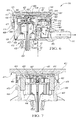
- Vent valve assembly 410 is designed to be mounted within a fuel tank 411 (shown in fragmentary cross-sectional view in FIG. 7 ) to control venting of fuel vapor from the fuel tank 411.
- the vent valve assembly 410 includes both a liquid-vapor discriminating valve (LVDV) 412 and a pressure-holding valve (PHV) 414, also referred to herein as a first valve and a second valve, respectively.
- the vent valve assembly 410 is configured for ease of assembly along a single axis E3 with a reduced number of assembly steps.
- the pressure-holding valve 414 is laterally-offset from the LVDV 412. This allows the LVDV 412 to be positioned closer to an upper wall of the fuel tank 411, resulting in the LVDV 412 closing at a higher fuel height.
- the vent valve assembly 410 includes an inner cap 413 as well as three housing components: a first housing component 420, a second housing component 422, and a third housing component 424.
- the first housing component 420 is also referred to as a lower housing component as it is lowest within the fuel tank 411 when the valve assembly 410 is mounted within the tank 411.
- the second housing component 422 is referred to herein as a middle housing component or midplate, as it is sandwiched and trapped between the upper housing component 424 and the lower housing component 420 when the vent valve assembly 410 is assembled.
- the third housing component 424 is referred to herein as an upper housing component or as an outer cap, as it is highest in the fuel tank 411 when the vent valve assembly 410 is mounted within the fuel tank 411.
- the third housing component 424 can mount directly to an inner surface 417 of a fuel tank member such as the upper wall of the fuel tank 411 or a tank attachment device similar to tank attachment device 27 of FIG. 1 .
- the third housing component 424 has a mounting portion 429 with extensions 425 forming cavities 427 in an upper surface. If the fuel tank 411 is plastic, when the fuel tank 411 is relatively hot, the upper housing component 424 can be pressed to an inner surface 417 of an upper wall of the fuel tank 411, causing material of both the upper housing component 424 and the fuel tank 411 to fuse together, with material of the fuel tank 411 filling the cavities 427 as shown in FIG. 7 , forming an integral joint. It will be appreciated in light of the disclosure that the inner cap 413, the first housing component 420, the second housing component 422, and the third housing component 424 provide ornamental features aside from the functional features described herein.
- the middle housing component 422 includes a first opening 426 above the LVDV 412 and a second opening 428 above the PHV 414, rather than below as in the embodiments of FIGS. 1 and 2 .
- the second opening 428 is both axially-displaced and laterally-displaced from the first opening 426.
- the middle housing component 422 establishes a nonlinear flow path between the lower housing component 420 and the inner cap 413 to direct vapor flow from the LVDV 412 to the PHV 414, thereby allowing the PHV 414 to be laterally-spaced from the LVDV 412 instead of directly above the LVDV 412.
- the LVDV 412 includes a float 430 that is spring-biased toward the opening 426 by a spring 432.
- An opening 434 in the lower housing component 420 allows vapor to pass through the lower housing portion 420 and through the opening 426.
- the float 430 rises to block the opening 426.
- a peel-away device 435 hinged to the float 430 at pivot 436 blocks the opening 426 when the float 430 rises.
- the float 430 rises a predetermined amount from a lowered position shown to the shutoff position in which the peel-away device 435 is against the middle housing component 422 at the opening 426.
- the axial position of the first opening 426 is closer to the inner cap 413 than the second opening 428.
- the float 430 and the peel away valve 435 of the LVDV 412 move past the axial position of the second opening 428 when the float 430 rises to the shutoff position. Because vapor is not vented, liquid level within the tank 411 can no longer rise and liquid fuel backs up within a fuel pipe to shut off a dispensing nozzle (not shown). If vapor pressure within the fuel tank 411 rises above a predetermined pressure, however, the balance of forces on the peel-away device 435 will cause it to peel away from the opening 426 sufficiently to relieve vapor pressure.
- the middle housing component 422 has a wall portion 446 that forms an island. Forward of the cross-section area shown, the middle housing component 422 slopes downward from the wall portion 446, similar to the slope shown on either end of wall portion 446 as is apparent in FIG. 10 .
- the first opening 426 is in fluid communication with the second opening 428 around all sides of the wall portion 446. This allows vapor flow from the first opening 426 to the second opening 428. When liquid level within the tank 411 falls so that the float 430 is lowered as shown in FIG. 6 , vapor also vents along the flow path of arrow A3.
- the PHV 414 includes a spring-biased valve body 440 biased to a closed position (shown) by a spring 441 to block the second opening 428 unless vapor pressure above the second opening 428 rises to a predetermined level, at which point the valve body 440 compresses the spring 441, allowing vapor that has flowed along the vapor flow path A3 from the first opening 426 to the second opening 428, as indicated by arrow B3, to continue along the vapor flow path, as indicated by arrow C3, through a vent valve assembly outlet 444 to a vapor recovery system.
- the valve body 440 is not lowered in FIG.
- a small bypass vent opening 443 in the second housing component 422 adjacent the second opening 428 allows some pressure and vacuum relief of the fuel tank 411 even if the second opening 428 is blocked by the valve body 440 by permitting vapor flow between the fuel tank 411 and outlet 444 through the bypass vent opening 443, such as when a pressure differential between the pressure at the outlet 444 and a pressure in the tank 411 is above a predetermined level.
- the middle housing component 422 has the laterally-extending wall portion 446 forming the island, as well as axially extending continuous and concentric circular ridges 452.
- a continuous circular recess 453 is formed by the ridges 452 between the ridges 452 that extend toward the inner plate 413 and the mounting portion 429 of the third housing component 424.
- the middle housing component 422 is open above the first and second openings 426, 428, and therefore requires another component to enclose a space above the openings 426, 428 to establish with the first and second housing components 420, 422 the entire nonlinear flow path from the first opening 426 to the second opening 428, directing vapor flow from the LVDV 412 to the PHV 414.
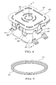
- the inner cap 413 is configured with a continuous circular flange 455 that extends toward the second housing component 422 and away from the mounting portion 429, and is configured to fit in the recess 453 between the ridges 452 when attached to the second housing component 422.
- the inner cap 413 and the second housing component 422 can both be plastic, in which case the inner cap 413 can be secured to the second housing component 422 at the ridges 452 by sonic welding.
- Other plastic joining methods can be used instead of sonic welding, such as vibration welding, laser welding, infrared welding, the use of an O-ring, a labyrinth seal, or snaps.
- a continuous sealed joint 457 is established at the recess 453.
- the inner cap 413 then cooperates with the second housing component 422 to enclose an upper extent of a vapor cavity 462 (indicated in FIG. 6 ) on the opposite side of the second housing component 422 from the valve bodies 430, 440.
- the third housing component 424 can be placed over the inner cap 413 and secured to the first housing component 420, as shown in FIG. 7 .
- snap tabs 468 extending from the third housing component 424 fit within tab retainers 470 extending from the first housing component 422, to secure the third housing component 424 to the first housing component 420, with the inner cap 413, the second housing component 422, and the valves 412, 414 sandwiched therebetween.
- the third housing component 424 when the third housing component 424 is secured directly to the inner surface 417 of the fuel tank 411, such as by heat fusion, and the cap 413 is joined to the second housing component 422, such as by sonic welding, an inner surface 463 of the mounting portion 429 of the third housing component 424 extends over but is slightly spaced from the inner cap 413.
- the third housing component 424 thus functions as an outer cap of the valve assembly 410.
- the upper housing component 424, middle housing component 422 and lower housing component 420 are configured with complementary features allowing them to be assembled to one another in one direction D3 along the single axis E3.
- the upper housing component 424 has tabs 468 that snap into retainers 470 of the lower housing component 420.
- the upper housing component 424 could have retainers 470 and the lower housing component 420 could have tabs 468.
- Other types of complementary features could be used to secure the third housing component 424 to the first housing component 422.
- the valve body 440 and spring 441 are placed on the lower housing component 420, and the float 430 and spring 432 are also placed on the lower housing component 420.
- the lower housing component 420 is moved toward the middle housing component 422.
- the lower housing component 420 also has ridges 460 that press-fit to wall portions 461 of the middle housing component 422 to form labyrinth seals 464.
- the ridges 460 are appropriately aligned with the wall portions 461 when the lower housing component 420 is moved toward the middle housing component 422.
- side walls 471 of the middle housing component 422 are supported on side walls 473 of the lower housing component 420.
- the side walls 471, 473 are also shown in FIG. 10 .
- the inner cap 413 is secured to the second housing component 422 to establish a sealed joint 457 and to define and enclose the vapor flow path A3.
- the third housing component 424 can then be snap-fit to the first housing component 420.
- the third housing component 424 is then attached to the inner surface 417 of the fuel tank 411, such as by heat fusion. With this arrangement, the inner cap 413 forms the upper boundary of the flow path A3 from the first opening 426 to the second opening 428.
Landscapes
- Engineering & Computer Science (AREA)
- General Engineering & Computer Science (AREA)
- Mechanical Engineering (AREA)
- Cooling, Air Intake And Gas Exhaust, And Fuel Tank Arrangements In Propulsion Units (AREA)
- Supplying Secondary Fuel Or The Like To Fuel, Air Or Fuel-Air Mixtures (AREA)
- Self-Closing Valves And Venting Or Aerating Valves (AREA)
- Safety Valves (AREA)
- Valve Housings (AREA)
Abstract
Description
- This application is a continuation-in-part of
U.S. Application No. 13/334,519, filed on December 22, 2011 - The present teachings generally include a vent valve assembly and a method of assembling a vent valve assembly.
- Fuel tank vent valve assemblies are used to regulate the vapor pressure within the fuel tank by allowing the venting of vapors under predetermined conditions. Some vent valve assemblies integrate more than one valve in a common housing. Assembly of vent valve assemblies having multiple valves and housing components can be complex and time-consuming.
- A vent valve assembly with a first valve and a second valve is provided with a configuration that simplifies assembly and provides a minimal height profile. The vent valve assembly includes a first housing component, a second housing component secured to the first housing component, and a third housing component. An inner cap is joined to the second housing component at a sealed joint. The third housing component secures to the first housing component such that the inner cap, the second housing component, the first valve and the second valve are surrounded by the first and third housing components. The first and the second housing components and the inner cap define a nonlinear vapor flow path that directs vapor from the first valve to the second valve.
- In one embodiment, the third housing component can be attached to a fuel tank member, such as to the inner surface of a fuel tank. For example, the third housing component can be heat fused to the fuel tank. Because the inner cap and not the third housing component defines the vapor flow path between the first and second valves, the integrity of the sealed joint of the inner cap to the second housing component is not compromised by expansion or contraction of the third housing component associated with the process of attaching the third housing component to the fuel tank.
- The first, second, and third housing components are configured to assemble together along one directional axis with the second housing component, the first valve and the second valve between the first and third housing components and with the second valve laterally-spaced from the first valve. An overall height of the vent valve assembly is thus minimized. In an embodiment in which the first valve is a liquid-vapor discriminating valve and the second valve is a pressure-holding valve, the minimal height of the vent valve assembly allows the liquid-vapor discriminating valve to be positioned higher in the fuel tank, resulting in a higher fuel shutoff height.
- A method of assembling a fuel tank vent valve assembly having a first valve and a second valve includes assembling first, second, and third housing components to one another along one directional axis, with the first valve positioned at a first opening in the second housing component, and the second valve positioned at a second opening in the second housing component. The method includes securing a cap to the second housing component so that the first housing component, the second housing component, and the cap define a vapor flow path that directs vapor from the first valve to the second valve. The method further includes securing a third housing component to the first housing component such that the inner cap, the second housing component, the first valve and the second valve are surrounded by the first and the third housing components.
- Because the housing components of the vent valve assembly are configured to be assembled along one directional axis, assembly is simplified and assembly time is reduced. Even with the second valve laterally displaced from the first valve, assembly of the valves and housing components is along only one directional axis. With previous vent valve assemblies, housing components were required to be assembled from several directions along multiple directional axes. With the present teachings, assembly fixtures that hold the components need to be positioned to move only along a single directional axis, reducing floor space necessary for the assembly process.
- The above features and advantages and other features and advantages of the present teachings are readily apparent from the following detailed description of the best modes for carrying out the present teachings when taken in connection with the accompanying drawings.
-
-
FIGURE 1 is a schematic cross-sectional illustration of a first embodiment of a vent valve assembly that has a liquid-vapor discriminating valve and a pressure-holding valve. -
FIGURE 2 is a schematic cross-sectional illustration of a second embodiment of a vent valve assembly that has a liquid-vapor discriminating valve and a pressure-holding valve. -
FIGURE 3 is a schematic illustration in exploded view of the vent valve assembly ofFigure 2 . -
FIGURE 4 is a schematic cross-sectional illustration of a third embodiment of a vent valve assembly that has a liquid-vapor discriminating valve and a pressure-holding valve. -
FIGURE 5 is a schematic cross-sectional illustration of a fourth embodiment of a vent valve assembly that has a liquid-vapor discriminating valve and a pressure-holding valve. -
FIGURE 6 is a schematic illustration in partial cross-sectional view of a fourth embodiment of a vent valve assembly that has a liquid-vapor discriminating valve and a pressure-holding valve. -
FIGURE 7 is a schematic illustration in partial cross-sectional view of the vent valve assembly ofFIG. 6 taken at lines 7-7 inFIG. 8 . -
FIGURE 8 is a schematic illustration in perspective view of the vent valve assembly ofFIG. 6 . -
FIGURE 9 is a schematic illustration in perspective view of an inner cap of the vent valve assembly ofFIG. 6 . -
FIGURE 10 is a schematic illustration in exploded perspective view of the vent valve assembly ofFIG. 6 . - Referring to the drawings, wherein like reference numbers refer to like components throughout the several views,
FIG. 1 shows avent valve assembly 10 designed to be mounted within afuel tank 11 to control venting of fuel vapor from the fuel tank. Thevent valve assembly 10 includes both a first valve, which in this embodiment is a liquid-vapor discriminating valve (LVDV) 12 and a second valve, which in this embodiment is a pressure-holding valve (PHV) 14. Thevent valve assembly 10 is configured for ease of assembly along a single directional axis E with a reduced number of assembly steps. Additionally, the pressure-holding valve 14 is laterally-offset from theLVDV 12. This allows theLVDV 12 to be positioned closer to an upper wall of thefuel tank 11 when thevent valve assembly 10 is mounted within thefuel tank 11, resulting in theLVDV 12 closing at a higher fuel height. - The
vent valve assembly 10 includes three housing components: afirst housing component 20, asecond housing component 22, and athird housing component 24. Thefirst housing component 20 is also referred to as a lower housing component as it is lowest within thefuel tank 11 when thevalve assembly 10 is mounted within thetank 11. Thethird housing component 24 is referred to herein as an upper housing component, as it is highest in thefuel tank 11 when thevent valve assembly 10 is mounted within thefuel tank 11. Thesecond housing component 22 is referred to herein as a middle housing component or midplate, as it is sandwiched and trapped between theupper housing component 24 and thelower housing component 20 when thevent valve assembly 10 is assembled. Thethird housing component 24 mounts to atank attachment device 27, which is configured to mount to thefuel tank 11. For example, thetank attachment device 27 can be a component that fits within an opening in thefuel tank 11 to support thevent valve assembly 10 to the upper wall of thefuel tank 11. Alternatively, thetank attachment device 27 can be a component that fuses to thefuel tank 11 when the material of thefuel tank 11 is relatively hot. Still further, thethird housing component 24 could be configured to mount directly to thefuel tank 11 by heat fusion, as described with respect to the embodiments ofFIGS. 2 ,4 or 5 . It will be appreciated in light of the disclosure that thefirst housing component 20, thesecond housing component 22, and thethird housing component 24 provide ornamental features aside from the functional features described herein. - The
middle housing component 22 includes afirst opening 26 above the LVDV 12 and a second opening 28 below thePHV 14. Thesecond opening 28 is thus both laterally-spaced and axially-displaced from thefirst opening 26. Themiddle housing component 22 establishes a nonlinear flow path between thelower housing component 20 and theupper housing component 24 to direct vapor flow from theLVDV 12 to thePHV 14, thereby allowing thePHV 14 to be laterally-spaced from theLVDV 12 instead of directly above theLVDV 12. - The LVDV 12 includes a
float 30 that is spring-biased toward the opening 26 by aspring 32. Anopening 34 in thelower housing portion 20 allows vapor to pass through thelower housing portion 20 and through theopening 26. When liquid fuel level in thefuel tank 11 is at a predetermined level, thefloat 30 rises to block theopening 26. A peel-away device 35 hinged to thefloat 30 atpivot 36 blocks the opening 26 when thefloat 30 rises. Thefloat 30 rises apredetermined amount 31 from the lowered position shown to a shutoff position in which the peel-away device 35 is against themiddle housing component 22 at the opening 26. Because vapor is not vented, liquid level within thetank 11 can no longer rise and liquid fuel backs up within a fuel pipe to shut off a dispensing nozzle (not shown). If vapor pressure within thefuel tank 11 rises above a predetermined pressure, however, the balance of forces on the peel-away device 35 will cause it to peel away from the opening 26 sufficiently to relieve vapor pressure. Because vapor can be vented in this manner while liquid cannot, theLVDV 12 discriminates between vapor and liquid and is referred to as a liquid-vapor discriminating valve. Vapor then passes from the fuel tank vapor space throughopening 34 andfirst opening 26 along vapor flow path indicated by arrow A. When liquid level within thetank 11 falls so that thefloat 30 is lowered as shown inFIG.1 , vapor also vents along the flow path of arrow A. - The
PHV 14 includes a weighted ball 40 positioned within aretainer 42 formed by themiddle housing component 22. Gravity causes the ball 40 to block thesecond opening 28 unless vapor pressure below theopening 28 rises to a predetermined level, at which point the ball 40 lifts, allowing vapor that has flowed along the vapor flow path from thefirst opening 26 to thesecond opening 28, as indicated by arrow B, to continue along the vapor flow path, as indicated by arrow C, through a ventvalve assembly outlet 44 to a vapor recovery system. Themiddle housing portion 22 has a laterally-extendingwall portion 46, axial-extendingwall portions first opening 26 to thesecond opening 28, directing vapor flow from theLVDV 12 to thePHV 14. - The
upper housing component 24,middle housing component 22 andlower housing component 20 are configured with complementary features allowing them to be assembled to one another in a direction D along a single axis E. That is, thevent valve assembly 10 assembles along a single axis parallel to the direction of extension of theridges upper housing component 24 hasridges 50 that press-fit toridges 52 of themiddle housing component 22 at various locations to form labyrinth seals 54. The ball 40 is placed on themiddle housing component 22 within theretainer 42, and then themiddle housing component 22 is moved toward theupper housing component 24 in direction D to secure theridges 50 to theridges 52. Theridges 50 are appropriately aligned with theridges 52 when themiddle housing component 22 is moved toward theupper housing component 20. Alternatively, theupper housing component 24 may be moved toward themiddle housing component 22. It will be appreciated in light of the disclosure that thefirst housing component 20, thesecond housing component 22, and thethird housing component 24 provide ornamental features including an overall impression aside from the functional features associated with their relative orientation described herein. - Next, the
float 30 andspring 32 are supported on thelower housing component 20, and thelower housing component 20 is moved toward themiddle housing component 22 in direction D. Alternatively, themiddle housing component 22 may be moved downward toward thelower housing component 20 along axis E in a direction opposed to direction D. Thelower housing component 20 also has aridge 60 and awall portion 62 that press-fits to wallportion 48 of themiddle housing component 22 to form alabyrinth seal 64. Theridge 60 is appropriately aligned with thewall portion 62 when thelower housing component 20 is moved toward themiddle housing component 22. When thelower housing component 20 is fit to themiddle housing component 22, snap tabs extending from theupper housing component 24 fit within tab retainers extending from thelower housing component 20, to secure theupper housing component 24 to thelower housing component 20, with themiddle housing component 22 sandwiched therebetween. Although not visible in the cross-sectional view ofFIG.1 , substantiallysimilar snap tabs 168 andtab retainers 170 are shown on thevent valve assembly 110 ofFIG. 3 . The function of snap tabs and retainers for connecting plastic components are readily understandable to a person of ordinary skill in the art. In all embodiments, thesnap tabs 168 can be on either the first housing component or the third housing component, with the retainers on the other of the first housing component and the third housing component. - Alternatively, the
vent valve assembly 10 can be assembled along axis E by first assembling themiddle housing component 22 to thelower housing component 20, and then assembling theupper housing component 24 to themiddle housing component 22. It will be appreciated in light of the disclosure that themiddle housing component 22, thelower housing component 20, and theupper housing component 24 provide ornamental features aside from the functional features described herein. -
FIG. 2 shows another embodiment of avent valve assembly 110 that functions in a substantially similar manner asvent valve assembly 10.Vent valve assembly 110 is designed to be mounted within afuel tank 111 to control venting of fuel vapor from thefuel tank 111. Thevent valve assembly 110 includes both a liquid-vapor discriminating valve (LVDV) 112 and a pressure-holding valve (PHV) 114. Thevent valve assembly 110 is configured for ease of assembly along a single axis EE with a reduced number of assembly steps. Additionally, the pressure-holdingvalve 114 is laterally-offset from theLVDV 112. This allows theLVDV 112 to be positioned closer to an upper wall of thefuel tank 111, resulting in theLVDV 112 closing at a higher fuel height. - The
vent valve assembly 110 includes three housing components: afirst housing component 120, asecond housing component 122, and athird housing component 124. Thefirst housing component 120 is also referred to as a lower housing component as it is lowest within thefuel tank 111 when thevalve assembly 110 is mounted within thetank 111. Thesecond housing component 122 is referred to herein as a middle housing component or midplate, as it is sandwiched and trapped between theupper housing component 124 and thelower housing component 120 when thevent valve assembly 110 is assembled. Thethird housing component 124 is referred to herein as an upper housing component, as it is highest in thefuel tank 111 when thevent valve assembly 110 is mounted within thefuel tank 111. Theupper housing component 124 is configured to mount directly to theinner surface 117 of the upper wall of thefuel tank 111 by heat fusion. If thefuel tank 111 is a plastic material, theupper housing component 124 can be pressed against thefuel tank 111 when thefuel tank 111 is still relatively hot after injection molding. A portion of thefuel tank material 111 will flow into an opening 113 in theupper housing component 124, creating a fusion of thetank 111 to theupper housing component 124. The material within the opening 113 serves as a rivet. Additional similar openings in theupper housing component 124 for securing theupper housing component 124 to the fuel tank are also provided but are not visible in the cross-section ofFIG. 2 . - The
middle housing component 122 includes afirst opening 126 above theLVDV 112 and asecond opening 128 below thePHV 114. Thesecond opening 128 is both axially-displaced and laterally-displaced from thefirst opening 126. Themiddle housing component 122 establishes a nonlinear flow path between thelower housing component 120 and theupper housing component 124 to direct vapor flow from theLVDV 112 to thePHV 114, thereby allowing thePHV 114 to be laterally-spaced from theLVDV 112 instead of directly above theLVDV 112. - The
LVDV 112 includes afloat 130 that is spring-biased toward theopening 126 by aspring 132. Anopening 134 in thelower housing component 120 allows vapor to pass through thelower housing portion 120 and through theopening 126. When liquid fuel level in thefuel tank 111 is at a predetermined level, thefloat 130 rises to block theopening 126, as shown. A peel-awaydevice 135 hinged to thefloat 130 atpivot 136 blocks theopening 126 when thefloat 130 rises. Thefloat 130 rises a predetermined amount from a lowered position to the shutoff position shown in which the peel-awaydevice 135 is against themiddle housing component 122 at theopening 126. Because vapor is not vented, liquid level within thetank 111 can no longer rise and liquid fuel backs up within a fuel pipe to shut off a dispensing nozzle (not shown). If vapor pressure within thefuel tank 111 rises above a predetermined pressure, however, the balance of forces on the peel-awaydevice 135 will cause it to peel away from theopening 126 sufficiently to relieve vapor pressure. Vapor then passes from the fuel tank vapor space throughopening 134 andfirst opening 126 along vapor flow path indicated by arrow AA. When liquid level within thetank 111 falls so that thefloat 130 is lowered, vapor also vents along the flow path of arrow AA. - The
PHV 114 includes aweighted disc 140 positioned within aretainer 142 formed by theupper housing component 124. Gravity causes thedisc 140 to block thesecond opening 128 unless vapor pressure below theopening 128 rises to a predetermined level, at which point thedisc 140 lifts, allowing vapor that has flowed along the vapor flow path from thefirst opening 126 to thesecond opening 128, as indicated by arrow BB, to continue along the vapor flow path, as indicated by arrow CC, through a ventvalve assembly outlet 144 to a vapor recovery system. Themiddle housing portion 122 has a laterally-extendingwall portion 146, axial-extendingwall portions wall portion 151 that define a nonlinear flow path from thefirst opening 126 to thesecond opening 128, directing vapor flow from theLVDV 112 to thePHV 114. - The
upper housing component 124,middle housing component 122 andlower housing component 120 are configured with complementary features allowing them to be assembled to one another in one direction DD along a single axis EE. That is, thevent valve assembly 110 assembles along a single axis parallel to the direction of extension ofridges upper housing component 124 hasridges 150 that press-fit toridges 152 of themiddle housing component 122 at various locations to form labyrinth seals 154. Thedisc 140 is placed on themiddle housing component 122, and then themiddle housing component 122 is moved toward theupper housing component 124 in direction DD to secure theridges 150 to theridges 152. Theridges 150 are appropriately aligned with theridges 152 when themiddle housing component 122 is moved toward theupper housing component 124. Alternatively, theupper housing component 124 may be moved toward themiddle housing component 122. - Next, the
float 130 andspring 132 are supported on thelower housing component 120, and thelower housing component 120 is moved toward themiddle housing component 122 in direction DD. Alternatively, themiddle housing component 122 may be moved downward toward thelower housing component 120 along axis EE in a direction opposed to direction DD. Thelower housing component 120 also has aridge 160 and awall portion 162 that press-fits to wallportion 148 of themiddle housing component 122 to form alabyrinth seal 164. Theridge 160 is appropriately aligned with thewall portion 148 when thelower housing component 120 is moved toward themiddle housing component 122.Ridges 160 of thelower housing component 120 also fit to themiddle housing component 122 atridges 161 to form anotherlabyrinth seal 164. When thelower housing component 120 is fit to themiddle housing component 122,snap tabs 168 extending from theupper housing component 124 fit withintab retainers 170 extending from thelower housing component 120, to secure theupper housing component 124 to thelower housing component 120, with themiddle housing component 122 sandwiched therebetween. Thesnap tabs 168 andtab retainers 170 are shown inFIG. 3. FIG. 3 shows the components of thevent valve assembly 110 aligned for assembly as described. - Alternatively, the
vent valve assembly 110 can be assembled along axis EE by first assembling themiddle housing component 122 to thelower housing component 120, and then assembling theupper housing component 124 to themiddle housing component 122. It will be appreciated in light of the disclosure that themiddle housing component 122, thelower housing component 120, and theupper housing component 124 provide ornamental features aside from the functional features described herein. -
FIG. 4 shows a third embodiment of avent valve assembly 210 that functions in a substantially similar manner asvent valve assembly 10 ofFIG. 1 .Vent valve assembly 210 is designed to be mounted within afuel tank 211 to control venting of fuel vapor from thefuel tank 211. Thevent valve assembly 210 includes both a liquid-vapor discriminating valve (LVDV) 212 and a pressure-holding valve (PHV) 214. Thevent valve assembly 210 is configured for ease of assembly along a single axis E1 with a reduced number of assembly steps. Additionally, the pressure-holdingvalve 214 is laterally-offset from theLVDV 212. This allows theLVDV 212 to be positioned closer to an upper wall of thefuel tank 211, resulting in theLVDV 212 closing at a higher fuel height. - The
vent valve assembly 210 includes three housing components: afirst housing component 220, asecond housing component 222, and athird housing component 224. Thefirst housing component 220 is also referred to as a lower housing component as it is lowest within thefuel tank 211 when thevalve assembly 210 is mounted within thetank 211. Thesecond housing component 222 is referred to herein as a middle housing component or midplate, as it is sandwiched and trapped between theupper housing component 224 and thelower housing component 220 when thevent valve assembly 210 is assembled. Thethird housing component 224 is referred to herein as an upper housing component, as it is highest in thefuel tank 211 when thevent valve assembly 210 is mounted within thefuel tank 211. Thethird housing component 224 mounts directly to thefuel tank 211. Thethird housing component 224 hasextensions 225 formingcavities 227 in an upper surface. If thefuel tank 211 is plastic, when thefuel tank 211 is relatively hot, theupper housing component 224 can be pressed to aninner surface 217 of an upper wall of thefuel tank 211, causing material of both theupper housing component 224 and thefuel tank 211 to fuse together, with material of thefuel tank 211 filling thecavities 227, forming an integral joint. It will be appreciated in light of the disclosure that thefirst housing component 220, thesecond housing component 222, and thethird housing component 224 provide ornamental features aside from the functional features described herein. - The
middle housing component 222 includes afirst opening 226 above theLVDV 212 and asecond opening 228 above thePHV 214, rather than below as in the first two embodiments. Thesecond opening 228 is both axially-displaced and laterally-displaced from thefirst opening 226. Themiddle housing component 222 establishes a nonlinear flow path between thelower housing component 220 and theupper housing component 224 to direct vapor flow from theLVDV 212 to thePHV 214, thereby allowing thePHV 214 to be laterally-spaced from theLVDV 212 instead of directly above theLVDV 212. - The
LVDV 212 includes afloat 230 that is spring-biased toward theopening 226 by aspring 232. Anopening 234 in thelower housing component 220 allows vapor to pass through thelower housing portion 220 and through theopening 226. When liquid fuel level in thefuel tank 211 is at a predetermined level, thefloat 230 rises to block theopening 226. A peel-away device 235 hinged to thefloat 230 atpivot 236 blocks theopening 226 when thefloat 230 rises. Thefloat 230 rises a predetermined amount from a lowered position shown to the shutoff position in which the peel-away device 235 is against themiddle housing component 222 at theopening 226. Because vapor is not vented, liquid level within thetank 211 can no longer rise and liquid fuel backs up within a fuel pipe to shut off a dispensing nozzle (not shown). If vapor pressure within thefuel tank 211 rises above a predetermined pressure, however, the balance of forces on the peel-away device 235 will cause it to peel away from theopening 226 sufficiently to relieve vapor pressure. Vapor then passes from the fuel tank vapor space throughopening 234 andfirst opening 226 along vapor flow path indicated by arrow A 1. Themiddle housing component 222 has awall portion 246 that forms an island. Forward of the cross-section area shown, themiddle housing component 222 slopes downward from thewall portion 246, similar to the slope shown on either end ofwall portion 246. Theopening 226 is in fluid communication with theopening 228 around all sides of thewall portion 246. This allows vapor flow from theopening 226 to theopening 228. When liquid level within thetank 211 falls so that thefloat 230 is lowered as shown, vapor also vents along the flow path of arrow A1. - The
PHV 214 includes a spring-biasedvalve body 240 biased to a closed position (not shown) by aspring 241 to block thesecond opening 228 unless vapor pressure above theopening 228 rises to a predetermined level, at which point thevalve body 240 compresses thespring 241 as shown, allowing vapor that has flowed along the vapor flow path from thefirst opening 226 to thesecond opening 228, as indicated by arrow B1, to continue along the vapor flow path, as indicated by arrow Cl, through a ventvalve assembly outlet 244 to a vapor recovery system. Aball valve 243 within thevalve body 240 allows over-vacuum relief of thefuel tank 211 by permitting vapor flow into thefuel tank 211 throughoutlet 244 when a pressure differential between the pressure at theoutlet 244 and a pressure in thetank 211 is above a predetermined level. - The
middle housing portion 222 has the laterally-extendingwall portion 246 forming the island, axial-extendingwall portions wall portion 251 that define a nonlinear flow path from thefirst opening 226 to thesecond opening 228, directing vapor flow from theLVDV 212 to thePHV 214. - The
upper housing component 224,middle housing component 222 andlower housing component 220 are configured with complementary features allowing them to be assembled to one another in one direction D1 along a single axis E1. Specifically, theupper housing component 224 hasridges 250 that press-fit toridges 252 of themiddle housing component 222 at various locations to form labyrinth seals 254 when themiddle housing component 222 is moved toward theupper housing component 224 in a direction D1 along axis E1. Thevalve body 240 andspring 241 are placed on thelower housing component 220, and thefloat 230 andspring 232 are also placed on thelower housing component 220. Thelower housing component 220 is moved toward themiddle housing component 222. Thelower housing component 220 also hasridges 260 that press-fit to wallportions 261 of themiddle housing component 222 to form labyrinth seals 264. Theridges 260 are appropriately aligned with thewall portions 261 when thelower housing component 220 is moved toward themiddle housing component 222. When thelower housing component 220 is fit to themiddle housing component 222, snap tabs extending from theupper housing component 224 fit within tab retainers extending from thelower housing component 222, to secure theupper housing component 224 to thelower housing component 220, with themiddle housing component 222 sandwiched therebetween. The snap tabs and tab retainers are substantially similar to those shown inFIG. 3 . - Alternatively, the
vent valve assembly 210 can be assembled along axis E1 but in an opposing direction to direction D1 by first assembling themiddle housing component 222 to thelower housing component 220, and then assembling theupper housing component 224 to themiddle housing component 222. -
FIG. 5 shows another embodiment of avent valve assembly 310 that functions in a substantially similar manner asvent valve assembly 10.Vent valve assembly 310 is designed to be mounted within afuel tank 311 to control venting of fuel vapor from thefuel tank 311. Thevent valve assembly 310 includes both a liquid-vapor discriminating valve (LVDV) 312 and a pressure-holding valve (PHV) 314. Thevent valve assembly 310 is configured for ease of assembly along a single axis E2 with a reduced number of assembly steps. Additionally, the pressure-holdingvalve 314 is laterally-offset from theLVDV 312. This allows theLVDV 312 to be positioned closer to an upper wall of thefuel tank 311, resulting in theLVDV 312 closing at a higher fuel height. - The
vent valve assembly 310 includes three housing components: afirst housing component 320, asecond housing component 322, and athird housing component 324. Thefirst housing component 320 is also referred to as a lower housing component as it is lowest within thefuel tank 311 when thevalve assembly 310 is mounted within thetank 311. Thesecond housing component 322 is referred to herein as a middle housing component or midplate, as it is sandwiched and trapped between theupper housing component 324 and thelower housing component 320 when thevent valve assembly 310 is assembled. Thethird housing component 324 is referred to herein as an upper housing component, as it is highest in thefuel tank 311 when thevent valve assembly 310 is mounted within thefuel tank 311. Theupper housing component 324 is configured to mount directly to theinner surface 317 of the upper wall of thefuel tank 311 by heat fusion. If thefuel tank 311 is a plastic material, theupper housing component 324 can be mounted directly to thefuel tank 311 if pressed against thefuel tank 311 when thefuel tank 311 is still relatively hot after injection molding. Thethird housing component 324 hasextensions 325 formingcavities 327 in an upper surface. If thefuel tank 311 is plastic, when thefuel tank 311 is relatively hot, theupper housing component 324 can be pressed to thefuel tank 311, causing material of both theupper housing component 324 and thefuel tank 311 to fuse together, with material of thefuel tank 311 filling thecavities 327, forming an integral joint. It will be appreciated in light of the disclosure that thefirst housing component 320, thesecond housing component 322, and thethird housing component 324 provide ornamental features aside from the functional features described herein. - The
middle housing component 322 includes afirst opening 326 above theLVDV 312 and asecond opening 328 below thePHV 314. Thesecond opening 328 is both axially-displaced and laterally-displaced from thefirst opening 326. Themiddle housing component 322 establishes a nonlinear flow path between thelower housing component 320 and theupper housing component 324 to direct vapor flow from theLVDV 312 to thePHV 314, thereby allowing thePHV 314 to be laterally-spaced from theLVDV 312 instead of directly above theLVDV 312. - The
LVDV 312 includes afloat 330 that is spring-biased toward theopening 326 by aspring 332. Anopening 334 in thelower housing component 320 allows vapor to pass through thelower housing portion 320 and through theopening 326. When liquid fuel level in thefuel tank 311 is at a predetermined level, thefloat 330 rises to block theopening 326, as shown. A peel-awaydevice 335 hinged to thefloat 330 atpivot 336 blocks theopening 326 when thefloat 330 rises. Thefloat 330 rises a predetermined amount from a lowered position to the shutoff position shown in which the peel-awaydevice 335 is against themiddle housing component 322 at theopening 326. Because vapor is not vented, liquid level within thetank 311 can no longer rise and liquid fuel backs up within a fuel pipe to shut off a dispensing nozzle (not shown). If vapor pressure within thefuel tank 311 rises above a predetermined pressure, however, the balance of forces on the peel-awaydevice 335 will cause it to peel-away from theopening 326 sufficiently to relieve vapor pressure. Vapor then passes from the fuel tank vapor space throughopening 334 andfirst opening 326 along vapor flow path indicated by arrow A2. When liquid level within thetank 311 falls so that thefloat 330 is lowered, vapor also vents along the flow path of arrow A2. Themiddle housing component 322 has awall portion 346 that forms an island. Forward of the cross-section area shown, themiddle housing component 322 slopes downward from thewall portion 346, similar to the slope shown on either end ofwall portion 346. Theopening 326 is in fluid communication with theopening 328 around all sides of thewall portion 346. This allows vapor flow from theopening 326 to theopening 328. When liquid level within thetank 311 falls so that thefloat 330 is lowered as shown, vapor also vents along the flow path of arrow A2. - The
PHV 314 includes aweighted disc 340 positioned within aretainer 342 formed by theupper housing component 324. Gravity causes thedisc 340 to block thesecond opening 328 unless vapor pressure below theopening 328 rises to a predetermined level, at which point thedisc 340 lifts, allowing vapor that has flowed along the vapor flow path from thefirst opening 326 to thesecond opening 328, as indicated by arrow B2, to continue along the vapor flow path, as indicated by arrow C2, through a ventvalve assembly outlet 344 to a vapor recovery system. Themiddle housing portion 322 has axial-extendingwall portions wall portion 351 that define a nonlinear flow path from thefirst opening 326 to thesecond opening 328, directing vapor flow from theLVDV 312 to thePHV 314. Thelower housing portion 320 has anotherinlet 341 that is in communication with a separate valve or vapor source to vent through thePHV 314. - The
upper housing component 324,middle housing component 322 andlower housing component 320 are configured with complementary features that allow them to be assembled to one another in one direction D2 along a single axis E2. That is, thevent valve assembly 310 assembles along a single axis parallel to the direction of extension ofridges upper housing component 324 hasridges 350 that press-fit toridges 352 of themiddle housing component 322 at various locations to form labyrinth seals 354. Thedisc 340 is placed on themiddle housing component 322, and then themiddle housing component 322 is moved toward theupper housing component 324 in direction D2 to secure theridges 350 to theridges 352. Theridges 350 are appropriately aligned with theridges 352 when themiddle housing component 322 is moved toward theupper housing component 324. Alternatively, theupper housing component 324 may be moved toward themiddle housing component 322. - Next, the
float 330 andspring 332 are supported on thelower housing component 320, and thelower housing component 320 is moved toward themiddle housing component 322 in direction D2. Alternatively, themiddle housing component 322 may be moved downward toward thelower housing component 320 along axis E2 in a direction opposed to direction D2. Thelower housing component 320 also hasridges 360 that press-fit toridges 361 of themiddle housing component 322 to form alabyrinth seal 364. Theridges 360 are appropriately aligned with theridges 361 when thelower housing component 320 is moved toward themiddle housing component 322. When thelower housing component 320 is fit to themiddle housing component 322, snap tabs extending from the upper housing component fit within tab retainers extending from the lower housing component, to secure theupper housing component 324 to thelower housing component 320, with themiddle housing component 322 sandwiched therebetween. The snap tabs and tab retainers are substantially similar totabs 168 andretainers 170 shown in the embodiment ofFIG. 3 . Alternatively, thevent valve assembly 310 can be assembled along axis E2 by first assembling themiddle housing component 322 to thelower housing component 320, and then assembling theupper housing component 324 to themiddle housing component 322. -
FIG. 6 shows a fifth embodiment of avent valve assembly 410 that functions in a substantially similar manner asvent valve assembly 10 ofFIG. 1 .Vent valve assembly 410 is designed to be mounted within a fuel tank 411 (shown in fragmentary cross-sectional view inFIG. 7 ) to control venting of fuel vapor from thefuel tank 411. Thevent valve assembly 410 includes both a liquid-vapor discriminating valve (LVDV) 412 and a pressure-holding valve (PHV) 414, also referred to herein as a first valve and a second valve, respectively. Thevent valve assembly 410 is configured for ease of assembly along a single axis E3 with a reduced number of assembly steps. Additionally, the pressure-holdingvalve 414 is laterally-offset from theLVDV 412. This allows theLVDV 412 to be positioned closer to an upper wall of thefuel tank 411, resulting in theLVDV 412 closing at a higher fuel height. - The
vent valve assembly 410 includes aninner cap 413 as well as three housing components: afirst housing component 420, asecond housing component 422, and athird housing component 424. Thefirst housing component 420 is also referred to as a lower housing component as it is lowest within thefuel tank 411 when thevalve assembly 410 is mounted within thetank 411. Thesecond housing component 422 is referred to herein as a middle housing component or midplate, as it is sandwiched and trapped between theupper housing component 424 and thelower housing component 420 when thevent valve assembly 410 is assembled. Thethird housing component 424 is referred to herein as an upper housing component or as an outer cap, as it is highest in thefuel tank 411 when thevent valve assembly 410 is mounted within thefuel tank 411. Thethird housing component 424 can mount directly to aninner surface 417 of a fuel tank member such as the upper wall of thefuel tank 411 or a tank attachment device similar totank attachment device 27 ofFIG. 1 . - The
third housing component 424 has a mountingportion 429 withextensions 425 formingcavities 427 in an upper surface. If thefuel tank 411 is plastic, when thefuel tank 411 is relatively hot, theupper housing component 424 can be pressed to aninner surface 417 of an upper wall of thefuel tank 411, causing material of both theupper housing component 424 and thefuel tank 411 to fuse together, with material of thefuel tank 411 filling thecavities 427 as shown inFIG. 7 , forming an integral joint. It will be appreciated in light of the disclosure that theinner cap 413, thefirst housing component 420, thesecond housing component 422, and thethird housing component 424 provide ornamental features aside from the functional features described herein. - The
middle housing component 422 includes afirst opening 426 above theLVDV 412 and asecond opening 428 above thePHV 414, rather than below as in the embodiments ofFIGS. 1 and 2 . Thesecond opening 428 is both axially-displaced and laterally-displaced from thefirst opening 426. Themiddle housing component 422 establishes a nonlinear flow path between thelower housing component 420 and theinner cap 413 to direct vapor flow from theLVDV 412 to thePHV 414, thereby allowing thePHV 414 to be laterally-spaced from theLVDV 412 instead of directly above theLVDV 412. - The
LVDV 412 includes afloat 430 that is spring-biased toward theopening 426 by aspring 432. Anopening 434 in thelower housing component 420 allows vapor to pass through thelower housing portion 420 and through theopening 426. When liquid fuel level in thefuel tank 411 is at a predetermined level, thefloat 430 rises to block theopening 426. A peel-awaydevice 435 hinged to thefloat 430 atpivot 436 blocks theopening 426 when thefloat 430 rises. Thefloat 430 rises a predetermined amount from a lowered position shown to the shutoff position in which the peel-awaydevice 435 is against themiddle housing component 422 at theopening 426. The axial position of thefirst opening 426 is closer to theinner cap 413 than thesecond opening 428. In fact, thefloat 430 and the peel awayvalve 435 of theLVDV 412 move past the axial position of thesecond opening 428 when thefloat 430 rises to the shutoff position. Because vapor is not vented, liquid level within thetank 411 can no longer rise and liquid fuel backs up within a fuel pipe to shut off a dispensing nozzle (not shown). If vapor pressure within thefuel tank 411 rises above a predetermined pressure, however, the balance of forces on the peel-awaydevice 435 will cause it to peel away from theopening 426 sufficiently to relieve vapor pressure. Vapor then passes from the fuel tank vapor space throughopening 434 andfirst opening 426 along vapor flow path indicated by arrow A3. Themiddle housing component 422 has awall portion 446 that forms an island. Forward of the cross-section area shown, themiddle housing component 422 slopes downward from thewall portion 446, similar to the slope shown on either end ofwall portion 446 as is apparent inFIG. 10 . Thefirst opening 426 is in fluid communication with thesecond opening 428 around all sides of thewall portion 446. This allows vapor flow from thefirst opening 426 to thesecond opening 428. When liquid level within thetank 411 falls so that thefloat 430 is lowered as shown inFIG. 6 , vapor also vents along the flow path of arrow A3. - The
PHV 414 includes a spring-biasedvalve body 440 biased to a closed position (shown) by aspring 441 to block thesecond opening 428 unless vapor pressure above thesecond opening 428 rises to a predetermined level, at which point thevalve body 440 compresses thespring 441, allowing vapor that has flowed along the vapor flow path A3 from thefirst opening 426 to thesecond opening 428, as indicated by arrow B3, to continue along the vapor flow path, as indicated by arrow C3, through a ventvalve assembly outlet 444 to a vapor recovery system. Although thevalve body 440 is not lowered inFIG. 6 and thesecond opening 428 is therefore blocked, vapor flow is shown for purposes of illustration flowing through thesecond opening 428 as it would if thevalve body 440 were lowered. A small bypass vent opening 443 in thesecond housing component 422 adjacent thesecond opening 428 allows some pressure and vacuum relief of thefuel tank 411 even if thesecond opening 428 is blocked by thevalve body 440 by permitting vapor flow between thefuel tank 411 andoutlet 444 through thebypass vent opening 443, such as when a pressure differential between the pressure at theoutlet 444 and a pressure in thetank 411 is above a predetermined level. - As best shown in
FIG. 10 , themiddle housing component 422 has the laterally-extendingwall portion 446 forming the island, as well as axially extending continuous and concentriccircular ridges 452. A continuouscircular recess 453 is formed by theridges 452 between theridges 452 that extend toward theinner plate 413 and the mountingportion 429 of thethird housing component 424. Themiddle housing component 422 is open above the first andsecond openings openings second housing components first opening 426 to thesecond opening 428, directing vapor flow from theLVDV 412 to thePHV 414. Theinner cap 413 is configured with a continuouscircular flange 455 that extends toward thesecond housing component 422 and away from the mountingportion 429, and is configured to fit in therecess 453 between theridges 452 when attached to thesecond housing component 422. Theinner cap 413 and thesecond housing component 422 can both be plastic, in which case theinner cap 413 can be secured to thesecond housing component 422 at theridges 452 by sonic welding. Other plastic joining methods can be used instead of sonic welding, such as vibration welding, laser welding, infrared welding, the use of an O-ring, a labyrinth seal, or snaps. With any such form of attachment, such as with the sonic welding process, a continuous sealed joint 457 is established at therecess 453. Theinner cap 413 then cooperates with thesecond housing component 422 to enclose an upper extent of a vapor cavity 462 (indicated inFIG. 6 ) on the opposite side of thesecond housing component 422 from thevalve bodies - After the
inner cap 413 is joined to thesecond housing component 422, thethird housing component 424 can be placed over theinner cap 413 and secured to thefirst housing component 420, as shown inFIG. 7 . Specifically,snap tabs 468 extending from thethird housing component 424 fit withintab retainers 470 extending from thefirst housing component 422, to secure thethird housing component 424 to thefirst housing component 420, with theinner cap 413, thesecond housing component 422, and thevalves - Referring to
FIG. 7 , it is apparent that when thethird housing component 424 is secured directly to theinner surface 417 of thefuel tank 411, such as by heat fusion, and thecap 413 is joined to thesecond housing component 422, such as by sonic welding, aninner surface 463 of the mountingportion 429 of thethird housing component 424 extends over but is slightly spaced from theinner cap 413. Thethird housing component 424 thus functions as an outer cap of thevalve assembly 410. If thesecond housing component 422 rather than theinner cap 413 were to be joined to thethird housing component 424 to enclose the flow path, a joint between thesecond housing component 422 and thethird housing component 424 would need to be sufficient to maintain a sealing relationship between thesecond housing component 422 and thethird housing component 424 even under temperature-induced stress due to dimensional changes of thethird housing component 424 caused by heat fusion of thethird housing component 424 to thetank 411. However, by providing aninner cap 413 joined to thesecond housing component 422 at a joint that is isolated from thethird housing component 424, attachment processes of thethird housing component 424 to thefuel tank 411, and any associated dimensional changes of thethird housing component 424 do not affect the joint 457. It is apparent inFIGS. 7 that anupper surface 465 of theinner cap 413 facing aninner surface 463 off the mountingportion 429 of thethird housing component 424 is spaced from theinner surface 463 such that asmall gap 467 exists between theinner cap 413 and the mountingportion 429. In other words, theinner cap 413 is not directly attached to thethird housing component 424. Stresses on thethird housing component 424 are thus largely isolated from theinner cap 413. Additionally, because thethird housing component 424 does not form or define the vapor flow path, the use of differently configured third housing components is enabled. For example, a third housing component with a differently configured mounting portion for interfacing with a differently configured fuel tank could be used, while maintaining the same configurations of the remaining components of thevent valve assembly 410, thus achieving economies of scale - The
upper housing component 424,middle housing component 422 andlower housing component 420 are configured with complementary features allowing them to be assembled to one another in one direction D3 along the single axis E3. Specifically, theupper housing component 424 hastabs 468 that snap intoretainers 470 of thelower housing component 420. Alternatively, theupper housing component 424 could haveretainers 470 and thelower housing component 420 could havetabs 468. Other types of complementary features could be used to secure thethird housing component 424 to thefirst housing component 422. - The
valve body 440 andspring 441 are placed on thelower housing component 420, and thefloat 430 andspring 432 are also placed on thelower housing component 420. Thelower housing component 420 is moved toward themiddle housing component 422. Thelower housing component 420 also hasridges 460 that press-fit to wallportions 461 of themiddle housing component 422 to form labyrinth seals 464. Theridges 460 are appropriately aligned with thewall portions 461 when thelower housing component 420 is moved toward themiddle housing component 422. Additionally,side walls 471 of themiddle housing component 422 are supported onside walls 473 of thelower housing component 420. Theside walls FIG. 10 . - Next, the
inner cap 413 is secured to thesecond housing component 422 to establish a sealed joint 457 and to define and enclose the vapor flow path A3. Thethird housing component 424 can then be snap-fit to thefirst housing component 420. Thethird housing component 424 is then attached to theinner surface 417 of thefuel tank 411, such as by heat fusion. With this arrangement, theinner cap 413 forms the upper boundary of the flow path A3 from thefirst opening 426 to thesecond opening 428. - While the best modes for carrying out the many aspects of the present teachings have been described in detail, those familiar with the art to which these teachings relate will recognize various alternative aspects for practicing the present teachings that are within the scope of the appended claims.
Claims (16)
- A vent valve assembly comprising:a first housing component;a second housing component secured to the first housing component;a third housing component;an inner cap joined to the second housing component at a sealed joint;a first valve;a second valve;wherein the third housing component secures to the first housing component such that the inner cap, the second housing component, the first valve and the second valve are surrounded by the first and third housing components; and wherein the first and the second housing components and the inner cap define a vapor flow path that directs vapor from the first valve to the second valve.
- The vent valve assembly of claim 1, wherein the second housing component has continuous ridges that form a recess; wherein the inner cap has a continuous flange fit between the ridges in the recess,
wherein preferably the third housing component has a mounting portion that extends over the inner cap without securing to the inner cap. - The vent valve assembly of claim 2, wherein the continuous ridges extend toward the mounting portion; and wherein the continuous flange extends away from the mounting portion.
- The vent valve assembly of claim 2, wherein at least a portion of a surface of the inner cap facing the mounting portion is spaced from the mounting portion.
- The vent valve assembly of claim 1, wherein the second valve is laterally-spaced from the first valve; and wherein the first, the second, and the third housing components and the inner cap are configured to assemble together along one directional axis,
wherein preferably the first valve and the second valve are supported on the first housing component between the first housing component and the second housing component. - The vent valve assembly of claim 1, wherein the second housing component defines a first opening that functions as a vapor vent of the first valve; wherein the second housing component defines a second opening that functions as a vapor vent of the second valve; and wherein vapor flows from the first opening to the second opening.
- The vent valve assembly of claim 6, wherein the first valve is configured to block the first opening in the second housing component when the first valve is lifted by a predetermined amount; and wherein the second valve is configured to prevent vapor that has passed through the first opening from passing through the second opening in the second housing component when pressure of the vapor is below a predetermined pressure.
- The vent valve assembly of claim 6, wherein the second opening is axially-displaced from the first opening so that the vapor flow path through the vent valve assembly is nonlinear.
- The vent valve assembly of claim 1, wherein the first housing component and the second housing component are configured with complementary features that interfit to form a labyrinth seal to hold the first housing component to the second housing component.
- The vent valve assembly of claim 1, wherein one of the first housing component and the third housing component has tab retainers; and wherein the other of the first housing component and the third housing component has snap tabs extending therefrom and configured to snap into and be retained by the tab retainers to attach the first housing component to the third housing component.
- The vent valve assembly of claim 1 in combination with a fuel tank member, wherein the third housing component is configured to be secured directly to an inner surface of the fuel tank member.
- A vent valve assembly for a fuel tank comprising:a housing including a first, a second, and a third housing component;a liquid-vapor discriminating valve;a pressure-holding valve;wherein the first, second, and third housing components are configured to assemble to one another in one direction, with the second housing component sandwiched between the first and third housing components and the pressure-holding valve displaced laterally from the liquid-vapor discriminating valve;wherein the liquid-vapor discriminating valve is configured to block flow that passes through the first component from passing through a first opening in the second component when a float of the liquid-vapor discriminating valve is lifted by a predetermined amount to a shutoff position;wherein the pressure-holding valve is configured to prevent vapor that has passed through the first opening from passing through a second opening in the second housing component when pressure of the vapor is below a predetermined pressure; andwherein the liquid-vapor discriminating valve moves past an axial position of the second opening when the liquid-vapor discriminating valve is lifted to the shutoff position.
- The vent valve assembly of claim 12, wherein the first housing component and the second housing component are configured with complementary features that interfit to sealingly secure the first housing component to the second housing component; and
wherein the first housing component and the third housing are configured with complementary retaining features that secure the first housing component to the third housing component independently of the second housing component. - The vent valve assembly of claim 12, further comprising:an inner cap joined to the second housing component at a sealed joint;wherein the third housing component secures to the first housing component such that the inner cap, the second housing component, the first valve and the second valve are surrounded by the first and third housing components, the third housing component thereby functioning as an outer cap; and wherein the first and the second housing components and the inner cap define a vapor flow path that redirects vapor from the first valve to the second valve
- A method of assembling a fuel tank vent valve assembly having a first valve and a second valve, comprising:assembling a first and a second housing component to one another along one directional axis so that the first valve and the second valve are laterally displaced from one another, with the first valve positioned at a first opening in the second housing component, and the second valve positioned at a second opening in the second housing component;securing a cap to the second housing component so that the first housing component, the second housing component, and the cap define a vapor flow path that directs vapor from the first valve to the second valve; andsecuring a third housing component to the first housing component such that the cap, the second housing component, the first valve and the second valve are surrounded by the first and the third housing components.
- The method of claim 15, wherein said securing the cap is by sonic welding,
and wherein the method preferably further comprises:attaching the third housing component to an inner surface of a fuel tank member,and wherein further preferably said attaching is by heat fusion.
Applications Claiming Priority (1)
| Application Number | Priority Date | Filing Date | Title |
|---|---|---|---|
| US14/179,592 US9360872B2 (en) | 2011-12-22 | 2014-02-13 | Fuel tank vent valve assembly and method of assembly |
Publications (2)
| Publication Number | Publication Date |
|---|---|
| EP2908035A1 true EP2908035A1 (en) | 2015-08-19 |
| EP2908035B1 EP2908035B1 (en) | 2016-11-16 |
Family
ID=50927968
Family Applications (1)
| Application Number | Title | Priority Date | Filing Date |
|---|---|---|---|
| EP14171867.6A Active EP2908035B1 (en) | 2014-02-13 | 2014-06-11 | Fuel tank vent valve assembly and method of assembly |
Country Status (4)
| Country | Link |
|---|---|
| EP (1) | EP2908035B1 (en) |
| JP (1) | JP2015152170A (en) |
| KR (1) | KR20150095534A (en) |
| AU (1) | AU2014203140A1 (en) |
Citations (3)
| Publication number | Priority date | Publication date | Assignee | Title |
|---|---|---|---|---|
| EP1617113A1 (en) * | 2004-07-15 | 2006-01-18 | Eaton Corporation | Fuel vapor vent valve float assembly and method of making same |
| WO2009095780A2 (en) * | 2008-02-01 | 2009-08-06 | Eaton Corporation | Multi-function control valve for fuel vapor system |
| US20100282335A1 (en) * | 2009-05-11 | 2010-11-11 | Eaton Corporation | Fuel vapor vent valve with dynamic pressure relief |
-
2014
- 2014-06-09 KR KR1020140069447A patent/KR20150095534A/en not_active Withdrawn
- 2014-06-10 AU AU2014203140A patent/AU2014203140A1/en not_active Abandoned
- 2014-06-11 EP EP14171867.6A patent/EP2908035B1/en active Active
- 2014-06-11 JP JP2014120599A patent/JP2015152170A/en active Pending
Patent Citations (3)
| Publication number | Priority date | Publication date | Assignee | Title |
|---|---|---|---|---|
| EP1617113A1 (en) * | 2004-07-15 | 2006-01-18 | Eaton Corporation | Fuel vapor vent valve float assembly and method of making same |
| WO2009095780A2 (en) * | 2008-02-01 | 2009-08-06 | Eaton Corporation | Multi-function control valve for fuel vapor system |
| US20100282335A1 (en) * | 2009-05-11 | 2010-11-11 | Eaton Corporation | Fuel vapor vent valve with dynamic pressure relief |
Also Published As
| Publication number | Publication date |
|---|---|
| AU2014203140A1 (en) | 2015-08-27 |
| KR20150095534A (en) | 2015-08-21 |
| EP2908035B1 (en) | 2016-11-16 |
| JP2015152170A (en) | 2015-08-24 |
| BR102014014066A2 (en) | 2015-10-13 |
Similar Documents
| Publication | Publication Date | Title |
|---|---|---|
| US8689816B2 (en) | Fuel tank vent valve assembly and method of assembly | |
| US9360872B2 (en) | Fuel tank vent valve assembly and method of assembly | |
| CN101365619B (en) | Sealing plug with pressure compensation chamber | |
| CN105935501B (en) | Oil-water separation filter | |
| RU2454589C2 (en) | Tube ventilation system for fuel tank | |
| CN104471297B (en) | Valve module for the case of vehicle | |
| JP4074113B2 (en) | Connector for fuel tank | |
| MX2013008783A (en) | Irrigation valve. | |
| JP2006266265A (en) | Low-contour overfill restricting device having reverse distribution performance | |
| US10279679B2 (en) | Valve device | |
| CN102712250B (en) | Vehicle fuel system and parts thereof | |
| JP2012047169A (en) | Fuel tank valve device and fuel tank ventilation device | |
| EP2720895B1 (en) | Assembly with vapor vent valve and liquid trap for static leak prevention in vapor control system | |
| CN119965453A (en) | Battery housing, traction battery, motor vehicle and method for producing a battery housing | |
| EP3141784B1 (en) | Valve device | |
| CA3181435A1 (en) | Pressure vessel with multiple lateral outflow openings | |
| US10407297B2 (en) | Fueling apparatus | |
| CN108138711B (en) | Ventilation control valve for fuel tank | |
| EP2908035B1 (en) | Fuel tank vent valve assembly and method of assembly | |
| EP1515072B1 (en) | Fuel vapor vent valve and method of attaching same to a tank | |
| US20080053546A1 (en) | Valve seal structure for reservoir of a fuel delivery module | |
| BR102014014066B1 (en) | VENT VALVE ASSEMBLY AND METHOD FOR ASSEMBLING A FUEL TANK VENT VALVE ASSEMBLY | |
| CN109780281A (en) | A kind of tank pressure adjusting and integrated overturning control valve of ventilating |
Legal Events
| Date | Code | Title | Description |
|---|---|---|---|
| PUAI | Public reference made under article 153(3) epc to a published international application that has entered the european phase |
Free format text: ORIGINAL CODE: 0009012 |
|
| AK | Designated contracting states |
Kind code of ref document: A1 Designated state(s): AL AT BE BG CH CY CZ DE DK EE ES FI FR GB GR HR HU IE IS IT LI LT LU LV MC MK MT NL NO PL PT RO RS SE SI SK SM TR |
|
| AX | Request for extension of the european patent |
Extension state: BA ME |
|
| 17P | Request for examination filed |
Effective date: 20160212 |
|
| RBV | Designated contracting states (corrected) |
Designated state(s): AL AT BE BG CH CY CZ DE DK EE ES FI FR GB GR HR HU IE IS IT LI LT LU LV MC MK MT NL NO PL PT RO RS SE SI SK SM TR |
|
| RIC1 | Information provided on ipc code assigned before grant |
Ipc: B60K 15/035 20060101ALN20160404BHEP Ipc: F16K 24/04 20060101AFI20160404BHEP |
|
| GRAP | Despatch of communication of intention to grant a patent |
Free format text: ORIGINAL CODE: EPIDOSNIGR1 |
|
| INTG | Intention to grant announced |
Effective date: 20160610 |
|
| RAP1 | Party data changed (applicant data changed or rights of an application transferred) |
Owner name: EATON CORPORATION |
|
| GRAS | Grant fee paid |
Free format text: ORIGINAL CODE: EPIDOSNIGR3 |
|
| GRAA | (expected) grant |
Free format text: ORIGINAL CODE: 0009210 |
|
| AK | Designated contracting states |
Kind code of ref document: B1 Designated state(s): AL AT BE BG CH CY CZ DE DK EE ES FI FR GB GR HR HU IE IS IT LI LT LU LV MC MK MT NL NO PL PT RO RS SE SI SK SM TR |
|
| REG | Reference to a national code |
Ref country code: GB Ref legal event code: FG4D |
|
| REG | Reference to a national code |
Ref country code: CH Ref legal event code: EP |
|
| REG | Reference to a national code |
Ref country code: IE Ref legal event code: FG4D |
|
| REG | Reference to a national code |
Ref country code: AT Ref legal event code: REF Ref document number: 846266 Country of ref document: AT Kind code of ref document: T Effective date: 20161215 |
|
| REG | Reference to a national code |
Ref country code: DE Ref legal event code: R096 Ref document number: 602014004840 Country of ref document: DE |
|
| PG25 | Lapsed in a contracting state [announced via postgrant information from national office to epo] |
Ref country code: LV Free format text: LAPSE BECAUSE OF FAILURE TO SUBMIT A TRANSLATION OF THE DESCRIPTION OR TO PAY THE FEE WITHIN THE PRESCRIBED TIME-LIMIT Effective date: 20161116 |
|
| REG | Reference to a national code |
Ref country code: NL Ref legal event code: MP Effective date: 20161116 |
|
| REG | Reference to a national code |
Ref country code: LT Ref legal event code: MG4D |
|
| REG | Reference to a national code |
Ref country code: AT Ref legal event code: MK05 Ref document number: 846266 Country of ref document: AT Kind code of ref document: T Effective date: 20161116 |
|
| PG25 | Lapsed in a contracting state [announced via postgrant information from national office to epo] |
Ref country code: SE Free format text: LAPSE BECAUSE OF FAILURE TO SUBMIT A TRANSLATION OF THE DESCRIPTION OR TO PAY THE FEE WITHIN THE PRESCRIBED TIME-LIMIT Effective date: 20161116 Ref country code: LT Free format text: LAPSE BECAUSE OF FAILURE TO SUBMIT A TRANSLATION OF THE DESCRIPTION OR TO PAY THE FEE WITHIN THE PRESCRIBED TIME-LIMIT Effective date: 20161116 Ref country code: NL Free format text: LAPSE BECAUSE OF FAILURE TO SUBMIT A TRANSLATION OF THE DESCRIPTION OR TO PAY THE FEE WITHIN THE PRESCRIBED TIME-LIMIT Effective date: 20161116 Ref country code: NO Free format text: LAPSE BECAUSE OF FAILURE TO SUBMIT A TRANSLATION OF THE DESCRIPTION OR TO PAY THE FEE WITHIN THE PRESCRIBED TIME-LIMIT Effective date: 20170216 Ref country code: GR Free format text: LAPSE BECAUSE OF FAILURE TO SUBMIT A TRANSLATION OF THE DESCRIPTION OR TO PAY THE FEE WITHIN THE PRESCRIBED TIME-LIMIT Effective date: 20170217 |
|
| REG | Reference to a national code |
Ref country code: FR Ref legal event code: PLFP Year of fee payment: 4 |
|
| PG25 | Lapsed in a contracting state [announced via postgrant information from national office to epo] |
Ref country code: PT Free format text: LAPSE BECAUSE OF FAILURE TO SUBMIT A TRANSLATION OF THE DESCRIPTION OR TO PAY THE FEE WITHIN THE PRESCRIBED TIME-LIMIT Effective date: 20170316 Ref country code: ES Free format text: LAPSE BECAUSE OF FAILURE TO SUBMIT A TRANSLATION OF THE DESCRIPTION OR TO PAY THE FEE WITHIN THE PRESCRIBED TIME-LIMIT Effective date: 20161116 Ref country code: PL Free format text: LAPSE BECAUSE OF FAILURE TO SUBMIT A TRANSLATION OF THE DESCRIPTION OR TO PAY THE FEE WITHIN THE PRESCRIBED TIME-LIMIT Effective date: 20161116 Ref country code: FI Free format text: LAPSE BECAUSE OF FAILURE TO SUBMIT A TRANSLATION OF THE DESCRIPTION OR TO PAY THE FEE WITHIN THE PRESCRIBED TIME-LIMIT Effective date: 20161116 Ref country code: HR Free format text: LAPSE BECAUSE OF FAILURE TO SUBMIT A TRANSLATION OF THE DESCRIPTION OR TO PAY THE FEE WITHIN THE PRESCRIBED TIME-LIMIT Effective date: 20161116 Ref country code: RS Free format text: LAPSE BECAUSE OF FAILURE TO SUBMIT A TRANSLATION OF THE DESCRIPTION OR TO PAY THE FEE WITHIN THE PRESCRIBED TIME-LIMIT Effective date: 20161116 Ref country code: AT Free format text: LAPSE BECAUSE OF FAILURE TO SUBMIT A TRANSLATION OF THE DESCRIPTION OR TO PAY THE FEE WITHIN THE PRESCRIBED TIME-LIMIT Effective date: 20161116 |
|
| PG25 | Lapsed in a contracting state [announced via postgrant information from national office to epo] |
Ref country code: RO Free format text: LAPSE BECAUSE OF FAILURE TO SUBMIT A TRANSLATION OF THE DESCRIPTION OR TO PAY THE FEE WITHIN THE PRESCRIBED TIME-LIMIT Effective date: 20161116 Ref country code: CZ Free format text: LAPSE BECAUSE OF FAILURE TO SUBMIT A TRANSLATION OF THE DESCRIPTION OR TO PAY THE FEE WITHIN THE PRESCRIBED TIME-LIMIT Effective date: 20161116 Ref country code: DK Free format text: LAPSE BECAUSE OF FAILURE TO SUBMIT A TRANSLATION OF THE DESCRIPTION OR TO PAY THE FEE WITHIN THE PRESCRIBED TIME-LIMIT Effective date: 20161116 Ref country code: EE Free format text: LAPSE BECAUSE OF FAILURE TO SUBMIT A TRANSLATION OF THE DESCRIPTION OR TO PAY THE FEE WITHIN THE PRESCRIBED TIME-LIMIT Effective date: 20161116 Ref country code: SK Free format text: LAPSE BECAUSE OF FAILURE TO SUBMIT A TRANSLATION OF THE DESCRIPTION OR TO PAY THE FEE WITHIN THE PRESCRIBED TIME-LIMIT Effective date: 20161116 |
|
| REG | Reference to a national code |
Ref country code: DE Ref legal event code: R097 Ref document number: 602014004840 Country of ref document: DE |
|
| PG25 | Lapsed in a contracting state [announced via postgrant information from national office to epo] |
Ref country code: BG Free format text: LAPSE BECAUSE OF FAILURE TO SUBMIT A TRANSLATION OF THE DESCRIPTION OR TO PAY THE FEE WITHIN THE PRESCRIBED TIME-LIMIT Effective date: 20170216 Ref country code: BE Free format text: LAPSE BECAUSE OF FAILURE TO SUBMIT A TRANSLATION OF THE DESCRIPTION OR TO PAY THE FEE WITHIN THE PRESCRIBED TIME-LIMIT Effective date: 20161116 Ref country code: SM Free format text: LAPSE BECAUSE OF FAILURE TO SUBMIT A TRANSLATION OF THE DESCRIPTION OR TO PAY THE FEE WITHIN THE PRESCRIBED TIME-LIMIT Effective date: 20161116 Ref country code: IT Free format text: LAPSE BECAUSE OF FAILURE TO SUBMIT A TRANSLATION OF THE DESCRIPTION OR TO PAY THE FEE WITHIN THE PRESCRIBED TIME-LIMIT Effective date: 20161116 |
|
| PLBE | No opposition filed within time limit |
Free format text: ORIGINAL CODE: 0009261 |
|
| STAA | Information on the status of an ep patent application or granted ep patent |
Free format text: STATUS: NO OPPOSITION FILED WITHIN TIME LIMIT |
|
| 26N | No opposition filed |
Effective date: 20170817 |
|
| PG25 | Lapsed in a contracting state [announced via postgrant information from national office to epo] |
Ref country code: SI Free format text: LAPSE BECAUSE OF FAILURE TO SUBMIT A TRANSLATION OF THE DESCRIPTION OR TO PAY THE FEE WITHIN THE PRESCRIBED TIME-LIMIT Effective date: 20161116 |
|
| PG25 | Lapsed in a contracting state [announced via postgrant information from national office to epo] |
Ref country code: MC Free format text: LAPSE BECAUSE OF FAILURE TO SUBMIT A TRANSLATION OF THE DESCRIPTION OR TO PAY THE FEE WITHIN THE PRESCRIBED TIME-LIMIT Effective date: 20161116 |
|
| REG | Reference to a national code |
Ref country code: CH Ref legal event code: PL |
|
| REG | Reference to a national code |
Ref country code: IE Ref legal event code: MM4A |
|
| PG25 | Lapsed in a contracting state [announced via postgrant information from national office to epo] |
Ref country code: LU Free format text: LAPSE BECAUSE OF NON-PAYMENT OF DUE FEES Effective date: 20170611 Ref country code: CH Free format text: LAPSE BECAUSE OF NON-PAYMENT OF DUE FEES Effective date: 20170630 Ref country code: IE Free format text: LAPSE BECAUSE OF NON-PAYMENT OF DUE FEES Effective date: 20170611 Ref country code: LI Free format text: LAPSE BECAUSE OF NON-PAYMENT OF DUE FEES Effective date: 20170630 |
|
| REG | Reference to a national code |
Ref country code: FR Ref legal event code: PLFP Year of fee payment: 5 |
|
| PG25 | Lapsed in a contracting state [announced via postgrant information from national office to epo] |
Ref country code: MT Free format text: LAPSE BECAUSE OF NON-PAYMENT OF DUE FEES Effective date: 20170611 |
|
| REG | Reference to a national code |
Ref country code: DE Ref legal event code: R082 Ref document number: 602014004840 Country of ref document: DE Ref country code: DE Ref legal event code: R081 Ref document number: 602014004840 Country of ref document: DE Owner name: EATON INTELLIGENT POWER LIMITED, IE Free format text: FORMER OWNER: EATON CORPORATION, CLEVELAND, OHIO, US |
|
| GBPC | Gb: european patent ceased through non-payment of renewal fee |
Effective date: 20180611 |
|
| PG25 | Lapsed in a contracting state [announced via postgrant information from national office to epo] |
Ref country code: GB Free format text: LAPSE BECAUSE OF NON-PAYMENT OF DUE FEES Effective date: 20180611 |
|
| PG25 | Lapsed in a contracting state [announced via postgrant information from national office to epo] |
Ref country code: HU Free format text: LAPSE BECAUSE OF FAILURE TO SUBMIT A TRANSLATION OF THE DESCRIPTION OR TO PAY THE FEE WITHIN THE PRESCRIBED TIME-LIMIT; INVALID AB INITIO Effective date: 20140611 |
|
| PG25 | Lapsed in a contracting state [announced via postgrant information from national office to epo] |
Ref country code: CY Free format text: LAPSE BECAUSE OF FAILURE TO SUBMIT A TRANSLATION OF THE DESCRIPTION OR TO PAY THE FEE WITHIN THE PRESCRIBED TIME-LIMIT Effective date: 20161116 |
|
| PG25 | Lapsed in a contracting state [announced via postgrant information from national office to epo] |
Ref country code: MK Free format text: LAPSE BECAUSE OF FAILURE TO SUBMIT A TRANSLATION OF THE DESCRIPTION OR TO PAY THE FEE WITHIN THE PRESCRIBED TIME-LIMIT Effective date: 20161116 |
|
| PG25 | Lapsed in a contracting state [announced via postgrant information from national office to epo] |
Ref country code: TR Free format text: LAPSE BECAUSE OF FAILURE TO SUBMIT A TRANSLATION OF THE DESCRIPTION OR TO PAY THE FEE WITHIN THE PRESCRIBED TIME-LIMIT Effective date: 20161116 |
|
| PG25 | Lapsed in a contracting state [announced via postgrant information from national office to epo] |
Ref country code: AL Free format text: LAPSE BECAUSE OF FAILURE TO SUBMIT A TRANSLATION OF THE DESCRIPTION OR TO PAY THE FEE WITHIN THE PRESCRIBED TIME-LIMIT Effective date: 20161116 Ref country code: IS Free format text: LAPSE BECAUSE OF FAILURE TO SUBMIT A TRANSLATION OF THE DESCRIPTION OR TO PAY THE FEE WITHIN THE PRESCRIBED TIME-LIMIT Effective date: 20170316 |
|
| P01 | Opt-out of the competence of the unified patent court (upc) registered |
Effective date: 20230521 |
|
| PGFP | Annual fee paid to national office [announced via postgrant information from national office to epo] |
Ref country code: DE Payment date: 20250520 Year of fee payment: 12 |
|
| PGFP | Annual fee paid to national office [announced via postgrant information from national office to epo] |
Ref country code: FR Payment date: 20250520 Year of fee payment: 12 |