EP2907999A1 - Fuel injection valve - Google Patents
Fuel injection valve Download PDFInfo
- Publication number
- EP2907999A1 EP2907999A1 EP13845731.2A EP13845731A EP2907999A1 EP 2907999 A1 EP2907999 A1 EP 2907999A1 EP 13845731 A EP13845731 A EP 13845731A EP 2907999 A1 EP2907999 A1 EP 2907999A1
- Authority
- EP
- European Patent Office
- Prior art keywords
- fuel
- swirl
- needle valve
- stabilization chamber
- valve
- Prior art date
- Legal status (The legal status is an assumption and is not a legal conclusion. Google has not performed a legal analysis and makes no representation as to the accuracy of the status listed.)
- Granted
Links
Images


Classifications
-
- F—MECHANICAL ENGINEERING; LIGHTING; HEATING; WEAPONS; BLASTING
- F02—COMBUSTION ENGINES; HOT-GAS OR COMBUSTION-PRODUCT ENGINE PLANTS
- F02M—SUPPLYING COMBUSTION ENGINES IN GENERAL WITH COMBUSTIBLE MIXTURES OR CONSTITUENTS THEREOF
- F02M61/00—Fuel-injectors not provided for in groups F02M39/00 - F02M57/00 or F02M67/00
- F02M61/04—Fuel-injectors not provided for in groups F02M39/00 - F02M57/00 or F02M67/00 having valves, e.g. having a plurality of valves in series
- F02M61/08—Fuel-injectors not provided for in groups F02M39/00 - F02M57/00 or F02M67/00 having valves, e.g. having a plurality of valves in series the valves opening in direction of fuel flow
-
- F—MECHANICAL ENGINEERING; LIGHTING; HEATING; WEAPONS; BLASTING
- F02—COMBUSTION ENGINES; HOT-GAS OR COMBUSTION-PRODUCT ENGINE PLANTS
- F02M—SUPPLYING COMBUSTION ENGINES IN GENERAL WITH COMBUSTIBLE MIXTURES OR CONSTITUENTS THEREOF
- F02M61/00—Fuel-injectors not provided for in groups F02M39/00 - F02M57/00 or F02M67/00
- F02M61/04—Fuel-injectors not provided for in groups F02M39/00 - F02M57/00 or F02M67/00 having valves, e.g. having a plurality of valves in series
- F02M61/06—Fuel-injectors not provided for in groups F02M39/00 - F02M57/00 or F02M67/00 having valves, e.g. having a plurality of valves in series the valves being furnished at seated ends with pintle or plug shaped extensions
-
- B—PERFORMING OPERATIONS; TRANSPORTING
- B05—SPRAYING OR ATOMISING IN GENERAL; APPLYING FLUENT MATERIALS TO SURFACES, IN GENERAL
- B05B—SPRAYING APPARATUS; ATOMISING APPARATUS; NOZZLES
- B05B1/00—Nozzles, spray heads or other outlets, with or without auxiliary devices such as valves, heating means
- B05B1/26—Nozzles, spray heads or other outlets, with or without auxiliary devices such as valves, heating means with means for mechanically breaking-up or deflecting the jet after discharge, e.g. with fixed deflectors; Breaking-up the discharged liquid or other fluent material by impinging jets
-
- B—PERFORMING OPERATIONS; TRANSPORTING
- B05—SPRAYING OR ATOMISING IN GENERAL; APPLYING FLUENT MATERIALS TO SURFACES, IN GENERAL
- B05B—SPRAYING APPARATUS; ATOMISING APPARATUS; NOZZLES
- B05B1/00—Nozzles, spray heads or other outlets, with or without auxiliary devices such as valves, heating means
- B05B1/26—Nozzles, spray heads or other outlets, with or without auxiliary devices such as valves, heating means with means for mechanically breaking-up or deflecting the jet after discharge, e.g. with fixed deflectors; Breaking-up the discharged liquid or other fluent material by impinging jets
- B05B1/262—Nozzles, spray heads or other outlets, with or without auxiliary devices such as valves, heating means with means for mechanically breaking-up or deflecting the jet after discharge, e.g. with fixed deflectors; Breaking-up the discharged liquid or other fluent material by impinging jets with fixed deflectors
- B05B1/265—Nozzles, spray heads or other outlets, with or without auxiliary devices such as valves, heating means with means for mechanically breaking-up or deflecting the jet after discharge, e.g. with fixed deflectors; Breaking-up the discharged liquid or other fluent material by impinging jets with fixed deflectors the liquid or other fluent material being symmetrically deflected about the axis of the nozzle
-
- B—PERFORMING OPERATIONS; TRANSPORTING
- B05—SPRAYING OR ATOMISING IN GENERAL; APPLYING FLUENT MATERIALS TO SURFACES, IN GENERAL
- B05B—SPRAYING APPARATUS; ATOMISING APPARATUS; NOZZLES
- B05B1/00—Nozzles, spray heads or other outlets, with or without auxiliary devices such as valves, heating means
- B05B1/34—Nozzles, spray heads or other outlets, with or without auxiliary devices such as valves, heating means designed to influence the nature of flow of the liquid or other fluent material, e.g. to produce swirl
- B05B1/3405—Nozzles, spray heads or other outlets, with or without auxiliary devices such as valves, heating means designed to influence the nature of flow of the liquid or other fluent material, e.g. to produce swirl to produce swirl
-
- F—MECHANICAL ENGINEERING; LIGHTING; HEATING; WEAPONS; BLASTING
- F02—COMBUSTION ENGINES; HOT-GAS OR COMBUSTION-PRODUCT ENGINE PLANTS
- F02M—SUPPLYING COMBUSTION ENGINES IN GENERAL WITH COMBUSTIBLE MIXTURES OR CONSTITUENTS THEREOF
- F02M51/00—Fuel-injection apparatus characterised by being operated electrically
- F02M51/06—Injectors peculiar thereto with means directly operating the valve needle
- F02M51/061—Injectors peculiar thereto with means directly operating the valve needle using electromagnetic operating means
-
- F—MECHANICAL ENGINEERING; LIGHTING; HEATING; WEAPONS; BLASTING
- F02—COMBUSTION ENGINES; HOT-GAS OR COMBUSTION-PRODUCT ENGINE PLANTS
- F02M—SUPPLYING COMBUSTION ENGINES IN GENERAL WITH COMBUSTIBLE MIXTURES OR CONSTITUENTS THEREOF
- F02M61/00—Fuel-injectors not provided for in groups F02M39/00 - F02M57/00 or F02M67/00
- F02M61/04—Fuel-injectors not provided for in groups F02M39/00 - F02M57/00 or F02M67/00 having valves, e.g. having a plurality of valves in series
- F02M61/10—Other injectors with elongated valve bodies, i.e. of needle-valve type
- F02M61/12—Other injectors with elongated valve bodies, i.e. of needle-valve type characterised by the provision of guiding or centring means for valve bodies
-
- F—MECHANICAL ENGINEERING; LIGHTING; HEATING; WEAPONS; BLASTING
- F02—COMBUSTION ENGINES; HOT-GAS OR COMBUSTION-PRODUCT ENGINE PLANTS
- F02M—SUPPLYING COMBUSTION ENGINES IN GENERAL WITH COMBUSTIBLE MIXTURES OR CONSTITUENTS THEREOF
- F02M61/00—Fuel-injectors not provided for in groups F02M39/00 - F02M57/00 or F02M67/00
- F02M61/16—Details not provided for in, or of interest apart from, the apparatus of groups F02M61/02 - F02M61/14
- F02M61/162—Means to impart a whirling motion to fuel upstream or near discharging orifices
- F02M61/163—Means being injection-valves with helically or spirally shaped grooves
-
- F—MECHANICAL ENGINEERING; LIGHTING; HEATING; WEAPONS; BLASTING
- F02—COMBUSTION ENGINES; HOT-GAS OR COMBUSTION-PRODUCT ENGINE PLANTS
- F02M—SUPPLYING COMBUSTION ENGINES IN GENERAL WITH COMBUSTIBLE MIXTURES OR CONSTITUENTS THEREOF
- F02M61/00—Fuel-injectors not provided for in groups F02M39/00 - F02M57/00 or F02M67/00
- F02M61/16—Details not provided for in, or of interest apart from, the apparatus of groups F02M61/02 - F02M61/14
- F02M61/18—Injection nozzles, e.g. having valve seats; Details of valve member seated ends, not otherwise provided for
- F02M61/1806—Injection nozzles, e.g. having valve seats; Details of valve member seated ends, not otherwise provided for characterised by the arrangement of discharge orifices, e.g. orientation or size
Definitions
- the present invention relates to a fuel injection valve.
- a fuel supply of the internal combustion engine adopts a cylinder injection system in which fuel is injected directly to a combustion chamber for the purpose of improving transient response, improving volume efficiency by evaporation latent heat, and carrying out greatly retarded combustion for catalyst activation at low temperatures.
- the adoption of the cylinder injection system may cause oil dilution caused when spray fuel hits a wall of the combustion chamber as the spray fuel is in a form of liquid droplets, PM (Particulate Matter), and generation of smoke.
- Patent Document 1 In order to take measures against these phenomena, a swirl flow may be given to fuel injected from a fuel injection valve.
- Patent Document 1 and Patent Document 2 have been known, for example.
- Patent Document 2 describes a fuel injection valve configured such that a swirling component is given to fuel so that fine air bubbles are taken in injected fuel, thereby achieving atomization of the injected fuel by bursting the fine air bubbles.
- an object of a fuel injection valve described in the present specification is to atomize dead fuel.
- a fuel injection valve described in the present specification includes: a needle valve including a seat portion on a tip side thereof; a nozzle body including a seat surface on which the seat portion is placed, and a swirl stabilization chamber on a downstream side of the seat surface, the nozzle body having an injection hole formed so as to have an inlet in the swirl stabilization chamber; a swirl flow generating portion having swirl grooves configured to give a swirling component to fuel to be introduced into the swirl stabilization chamber; and a fuel collision portion provided in a tip portion of the needle valve, the fuel collision portion being configured such that, in a state where the needle valve is opened, the fuel collision portion intersects with a virtual surface extended toward the injection hole from the seat surface included in the nozzle body.
- the swirling component When the fuel passing through the swirl grooves so that a swirling component is given thereto is introduced into the swirl stabilization chamber, the swirling component is also given to fuel corresponding to the dead fuel having been retained in the swirl stabilization chamber, due to a force of swirling of the fuel thus introduced.
- the fuel to which the swirling component is given is introduced into the injection hole, and generates an air column in a central portion of a swirl flow of the fuel. Subsequently, fine air bubbles are generated in a boundary between the air column and the fuel, and the fuel including the fine air bubbles is injected from the injection hole. After the fuel is injected from the injection hole, the fine air bubbles burst, thereby achieving atomization of the fuel.
- the fuel collision portion it is possible to achieve atomization of the dead fuel.
- the fuel collision portion when the needle valve is opened, the fuel collision portion may be configured to incline a flow of the fuel to be introduced into the swirl stabilization chamber, toward an inner peripheral wall of the swirl stabilization chamber. This makes it possible to retain the dead fuel in the swirl stabilization chamber.
- the fuel collision portion may include a curved portion formed on its outer peripheral wall so as to be recessed toward an axial center of the needle valve.
- the dead fuel can be guided to the vicinity of the inner peripheral wall of the swirl stabilization chamber, so that the dead fuel can be effectively retained in the swirl stabilization chamber.
- the fuel collision portion may include a spiral groove on its external wall, and a swirl direction of the spiral groove relative to the axial center of the needle valve may be the same direction as a swirl direction of the swirl grooves provided in the needle guide relative to the axial center of the needle valve.
- a swirl direction of the spiral groove relative to the axial center of the needle valve may be the same direction as a swirl direction of the swirl grooves provided in the needle guide relative to the axial center of the needle valve.
- a tapered portion may be provided between the seat portion provided in the needle valve and the fuel collision portion. This makes it possible to restrain detachment of the fuel passing through the seat portion so as to be introduced into the swirl stabilization chamber, thereby making it possible to smoothly guide the dead fuel to the fuel collision portion. As a result, the dead fuel can be retained in the swirl stabilization chamber effectively. Further, when the detachment occurs at the time when the fuel is introduced into the swirl stabilization chamber, an unstable swirl flow is caused, so that unevenness in spray is easy to occur. However, the tapered portion can restrain this.
- a bottom face of the swirl stabilization chamber may be a smooth surface perpendicular to the axial center of the needle valve, and a central axis of the injection hole may coincide with the axial center of the needle valve. This makes it possible to introduce the swirl flow into the injection hole homogeneously. As a result, it is possible to achieve cone-shaped fuel injection formed in a symmetrical manner along the central axis of the injection hole.
- a distance between the inlet of the injection hole and the bottom face of the fuel collision portion when the needle valve is closed be set to not more than a quenching distance of flames to enter from the injection hole. This makes it possible to restrain the flames from entering into the fuel injection valve. As a result, it is possible to restrain carbonization of the fuel inside the fuel injection valve.
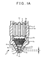
- FIG. 1(A) is an explanatory view illustrating a valve closed state of a fuel injection valve 1 of the first embodiment
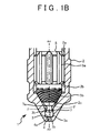
- FIG. 1(B) is an explanatory view illustrating a valve open state of the fuel injection valve 1 of the first embodiment
- FIG. 2 is an explanatory view illustrating a tip portion of the fuel injection valve 1 of the first embodiment in an enlarged manner
- FIG. 3 is a perspective view illustrating a tip portion of a needle guide 5 in the first embodiment.
- FIG. 4(A) is an explanatory view of the tip portion of the needle guide 5 when viewed from a side surface side
- FIG. 4(B) is an explanatory view of the needle guide 5 when viewed from a tip side.
- FIG. 4(A) is an explanatory view of the tip portion of the needle guide 5 when viewed from a side surface side
- FIG. 4(B) is an explanatory view of the needle guide 5 when viewed from a tip side.
- FIG. 5(A) is a perspective view illustrating a tip portion of a needle valve 6 in the first embodiment
- FIG. 5(B) is a side view illustrating the tip portion of the needle valve 6 in the first embodiment
- FIG. 6 is an explanatory view illustrating a principle of fuel atomization in the fuel injection valve 1 in the first embodiment.
- the fuel injection valve 1 of the first embodiment is provided in an internal combustion engine, and is drive-controlled by an ECU provided in the internal combustion engine.
- the ECU is a computer including a CPU (Central Processing Unit) configured to perform arithmetic processing, a ROM (Read Only Memory) in which to store a program and the like, and a RAM (Random Access Memory) or a NVRAM (Non Volatile RAM) in which to store data and the like,.
- the fuel injection valve 1 can be provided in a lower part of an inlet port provided in the internal combustion engine, or at a given position in a combustion chamber.
- the internal combustion engine in which the fuel injection valve 1 is provided is any of a gasoline engine using gasoline as fuel, a diesel engine using light oil as fuel, and a flexible fuel engine using fuel obtained by mixing gasoline with alcohol at a given ratio. Also, the internal combustion engine may be an engine using any fuel that can be injected by a fuel injection valve.
- the fuel injection valve 1 includes a nozzle body 2, a needle guide 5, and a needle valve 6 having an axial center AX.
- the nozzle body 2 is a tubular member, and includes an inner peripheral wall 2a. Further, the nozzle body 2 includes a pressure chamber 2b. A tip side of the pressure chamber 2b is provided with a seat surface 2c formed in a tapered shape. The after-mentioned seat portion 6a is placed on the seat surface 2c. Further, the nozzle body 2 includes a swirl stabilization chamber 3 on a downstream side of the seat surface 2c.
- the swirl stabilization chamber 3 is a cylindrical space having a bottom face 3a and an inner peripheral wall 3b. The bottom face 3a of the swirl stabilization chamber 3 is a smooth surface perpendicular to the axial center AX of the after-mentioned needle valve 6.
- An inlet 4a of the injection hole 4 is opened on the bottom face 3a.
- a central axis of the injection hole 4 coincides with the axial center AX of the needle valve 6.
- the fuel injection valve 1 in the first embodiment generates a strong swirl flow inside the injection hole 4 so as to generate fine air bubbles, and injects fuel including the fine air bubbles.
- the fuel flowing through the injection hole 4 forms a gas-liquid two-phase flow in which air bubbles are mixed, so that its flow speed is controlled at an extremely low sonic velocity prescribed by a void fraction.
- an injection hole diameter is set to a diameter that secures a flow rate of the fuel.
- the injection hole diameter of the injection hole 4 is set to 0.7 mm, and an injection hole area thereof is set to 0.385 mm 2 . Note that these dimensions are just examples and not limited to the above.
- the fuel injection valve 1 includes the needle guide 5 of which a tip portion is placed inside the nozzle body 2.
- the needle guide 5 is placed inside the nozzle body 2 so that an outer peripheral surface of the needle guide 5 makes contact with an inner peripheral wall 3b of the nozzle body 2 in a supported manner.
- the needle guide 5 is a tubular member, and the needle valve 6 is accommodated in an inner peripheral portion in a reciprocating manner along a direction of the axial center AX.
- the needle guide 5 includes a fuel communication path 5a on an outer peripheral wall surface on a base end side.
- a swirl groove 5b configured to give a swirling component to fuel to be introduced into the swirl stabilization chamber 3 is provided on a downstream side of the needle guide 5.
- the swirl groove 5b gives a swirling component to the fuel to be introduced into the swirl stabilization chamber 3.
- a tip portion of the needle guide provided with such a swirl groove 5b corresponds to a swirl flow generating portion.
- a groove width is 0.17 mm at the maximum.
- a depth Di of an inlet portion of the groove is 0.4 mm.
- a depth Do of an outlet portion of the groove is 0.16 mm.
- a total groove minimal area, that is, a total area of the groove at the outlet portion is 0.314 mm 2 .
- a groove flow path length is 4.5 mm.
- a calculated value of a pressure drop is 135 kPa.
- the fuel injection valve 1 includes the needle valve 6 having the seat portion 6a on a tip side. As described above, the needle valve 6 is supported by an inner side of the needle guide 5 in a reciprocating manner. The needle valve 6 performs an opening operation by a driving device operating in response to an instruction of the ECU. As illustrated in FIG. 1(A) , when the seat portion 6a is placed on the seat surface 2c, the fuel injection valve 1 enters a valve closed state. As illustrated in FIG. 1(B) , when the seat portion 6a is removed from the seat surface 2c, the fuel injection valve 1 enters a valve open state.
- the following describes dead fuel that is caused when the fuel injection valve 1 enters the valve closed state.
- fuel is retained in an upstream side relative to the seat portion 6a in a state where a set fuel pressure is maintained.
- the fuel retained at a position closer to the seat portion 6a is sequentially introduced into the swirl stabilization chamber 3.
- the needle valve 6 starts lifting, that part of the fuel which is retained in a dead fuel retention portion 8 formed in a region from the seat portion 6a to a downstream end of the swirl grooves 5b, that is, to the tip portion of the needle guide 5 is introduced into the swirl stabilization chamber 3 in a state where that part of the fuel hardly has a swirling component.
- the dead fuel is hard to be atomized due to the after-mentioned principle.
- a tip portion of the needle valve 6 is provided with the fuel collision portion 7.
- the fuel collision portion 7 is provided so that the dead fuel described above collides therewith.
- the dead fuel that has collided with the fuel collision portion 7 can be retained in the swirl stabilization chamber 3.
- the fuel collision portion 7 is provided so as to intersect with a virtual surface F extended from the seat surface 2c provided in the nozzle body 2 toward the injection hole 4, that is, toward a tip side of the nozzle body 2, in a state where the needle valve 6 is opened.
- the fuel passes between the seat surface 2c and the seat portion 6a with a width according to a distance therebetween, and is introduced into the swirl stabilization chamber 3.
- the dead fuel is also introduced into the swirl stabilization chamber 3 in the same manner.
- the virtual surface F extended from the seat surface 2c toward the injection hole 4 generally coincides with a boundary of a flow of the dead fuel. Accordingly, if the fuel collision portion 7 is provided so as to intersect with the virtual surface F, the dead fuel can collide with the fuel collision portion 7.
- the fuel collision portion 7 is provided so as to collide with the dead full even at the time when the needle valve 6 is fully lifted. Note that, in a case where the above condition is not satisfied, streams of the fuel passing through the seat portion 6a in a circumferential shape and gathering toward the axial center AX collide with each other, so that the streams of the fuel are injected from the injection hole 4 without being atomized.
- the fuel retained in the swirl stabilization chamber 3 collides with the fuel collision portion 7, so that the fuel is inclined toward the inner peripheral wall 3b of the swirl stabilization chamber 3. Then, a swirling component is given to the fuel from the fuel having the swirling component and introduced into the swirl stabilization chamber 3 subsequently to the dead fuel, and then, the fuel is introduced into the injection hole 4. That is, fuel placed in an upstream side relative to the dead fuel at the time when the fuel injection valve 1 is closed, and introduced into the swirl stabilization chamber 3 after passing through the swirl grooves 5b with a sufficient distance has a fast speed and obtains the swirling component.
- the fuel that passes through the swirl grooves 5b with a long inlet length and has the swirling component is introduced into the swirl stabilization chamber 3 along the inner peripheral wall 3b of the swirl stabilization chamber 3 due to a centrifugal force of the fuel.
- the fuel having the swirling component keeps the swirling component and is introduced into the injection hole 4 together with the fuel retained in the swirl stabilization chamber 3.
- the fuel collision portion 7 is configured to incline a flow of fuel to be introduced into the swirl stabilization chamber 3, toward the inner peripheral wall 3b of the swirl stabilization chamber 3. More specifically, as illustrated in FIGS. 5(A), 5(B) , the fuel collision portion 7 includes a curved portion 7a formed on its outer peripheral wall so as to be recessed toward the axial center AX of the needle valve 6.
- the dead fuel is guided to the vicinity of the inner peripheral wall 3b of the swirl stabilization chamber 3, so that the dead fuel is retained in the swirl stabilization chamber 3 effectively, thereby making it possible to secure a time before the fuel is introduced into the injection hole 4.
- the dead fuel guided to the vicinity of the inner peripheral wall 3b of the swirl stabilization chamber 3 is absorbed by the fuel having the swirling component at a fast speed, so that the deal fuel is easy to have the swirling component.
- a uniform fuel flow can be easily obtained.
- even in a case where the position of the injection hole is offset from the axial center AX, it is possible to restrain the fuel that is not swirling from being directly injected. As a result, it is possible to deal with a plurality of injection holes and an injection hole provided diagonally, thereby making it possible to improve design freedom.
- the bottom face 3a of the swirl stabilization chamber 3 of the fuel injection valve 1 is a smooth surface perpendicular to the axial center AX of the needle valve 6.
- the inlet 4a of the injection hole 4 is opened on the bottom face 3a, and the central axis of the injection hole 4 coincides with the axial center AX of the needle valve 6.
- This allows the fuel swirling in the swirl stabilization chamber 3 to be introduced into the injection hole 4 homogeneously.
- the following describes a state of the fuel injection by the fuel injection valve 1.
- the fuel passing through the fuel communication path 5a is once introduced into the pressure chamber 2b, and then flows into the swirl grooves 5b.
- the fuel forms a swirl flow.
- the swirl flow is introduced into the swirl stabilization chamber 3 along the seat surface 2c.
- the fuel swirling in the swirl stabilization chamber 3 is introduced into the injection hole 4.
- the fuel is introduced into the injection hole 4 having a diameter smaller than that of the swirl stabilization chamber 3, so that a whirl speed of the swirl flow accelerates and speeds up.
- a negative pressure is caused in a central part of the swirl flow, thereby generating an air column AP.
- fine air bubbles are generated, and the fine air bubbles thus generated are injected with the fuel.
- a principle of atomization of the fuel is described in detail as follows.
- a swirl flow with a fast whirl speed is formed in the fuel injection valve 1 and the swirl flow is introduced into the injection hole, a negative pressure is caused in a swirl center of such a strong swirl flow.
- air outside the fuel injection valve 1 is absorbed into the injection hole 4.
- an air column AP is generated within the injection hole 4.
- air bubbles are generated in an interface between the air column AP thus generated and the fuel.
- the air bubbles thus generated are mixed into the fuel flowing around the air column AP, so as to be injected with an air-bubble mixed flow, that is, a fuel flow that flows on an outer peripheral side as a two-phase flow.
- a shape of the injection is a hollow cone shape. Accordingly, as the injection is separated from the injection hole 4, an outside diameter of spray becomes larger, so that a liquid membrane forming the air bubble is stretched to be thinner. Then, when the liquid membrane cannot be maintained, the air bubble is divided. After that, a diameter of the fine air bubble is decreased due to a self-pressurizing effect, thereby causing collapse (crushing), so that ultrafine fuel particles are formed. Thus, atomization of the fuel is attained.
- the injection hole diameter of the injection hole 4 of the fuel injection valve 1 is set to 0.7 mm. This diameter corresponds to a distance that allows flames from the combustion chamber to enter the fuel injection valve 1.
- the fuel in the fuel injection valve 1 might be carbonized.
- poor oil-tight and aggravation of spray in the fuel injection valve 1 may be caused.
- a distance between the inlet 4a of the injection hole 4 and the bottom face 7b of the fuel collision portion 7 when the needle valve 6 is closed is set to a quenching distance or less for the flames entering from the injection hole 4. More specifically, a distance S shown in FIG. 1(A) is set to 0.4 mm or less.
- the quenching distance indicates a distance in which the flames are extinguished. When the flames are passing through a gap of a predetermined distance or less, heat of the flames is taken by a surrounding structural object, so that the flames are extinguished.
- the distance S is set on the premise that the quenching distance is 0.4 mm.
- the distance of 0.4 mm is not absolute, and other distances may be set provided that the flames are extinguished so as not to enter the fuel injection valve 1.
- a diameter of the bottom face 7b of the fuel collision portion 7 is set to be larger than the injection hole diameter.
- a fuel injection valve 11 of the second embodiment is different from the fuel injection valve 1 of the first embodiment in a shape of a needle valve, more specifically, a shape of a fuel collision portion. That is, the fuel injection valve 11 includes a needle valve 16 instead of the needle valve 6 provided in the fuel injection valve 1 of the first embodiment.
- the needle valve 16 includes a fuel collision portion 17 instead of the fuel collision portion 7. Note that the other configurations are the same as those of the first embodiment, so a constituent common in the first embodiment has the same reference sign in the figures, and a detailed description thereof is omitted.
- the fuel collision portion 17 includes a spiral groove 17a on an outer peripheral wall thereof.
- a swirl direction of the spiral groove 17a relative to an axial center AX of the needle valve 16 is the same direction as a swirl direction of swirl grooves 5b provided in a needle guide 5 relative to the axial center AX of the needle valve 16.
- the fuel collision portion 17 is provided at a position similar to that in the fuel injection valve 1 of the first embodiment. Accordingly, dead fuel introduced into a swirl stabilization chamber 3 at the beginning of opening of the fuel injection valve 11 collides with the fuel collision portion 17. The dead fuel that has collided with the fuel collision portion 17 moves along the spiral groove 17a so that the dead fuel can obtain a swirling component by itself.
- ⁇ 1 indicates an inclination of the swirl groove 5b relative to the axial center AX.
- ⁇ 2 indicates an inclination of the spiral groove 17a relative to the axial center AX.
- ⁇ 1 and ⁇ 2 are both inclined in a positive (+) direction relative to the axial center AX. That is, their swirl directions are the same. Accordingly, a swirling component given to the dead fuel by the spiral groove 17a does not obstruct a swirling component given to the dead fuel by the swirl groove 5b.
- the dead fuel can obtain a swirling component by itself by passing through the swirl groove 5b before a swirling component is given thereto by a fuel flow having the swirling component. This makes it possible to effectively swirl the fuel even under an environment of a low fuel pressure, for example, thereby making it possible to achieve atomization of the fuel.
- a fuel injection valve 21 of the third embodiment is different from the fuel injection valve 11 of the second embodiment in that the fuel injection valve 21 includes a tapered portion between a seat portion provided in a needle valve and a fuel collision portion. Further, the fuel injection valve 21 includes an injection hole 24 instead of the injection holes 4 provided in the fuel injection valve 1 of the first embodiment and in the fuel injection valve 11 of the second embodiment. Note that the other configurations are the same as those of the first embodiment, so a constituent common in the first embodiment has the same reference sign in the figures, and a detailed description thereof is omitted.
- the fuel injection valve 21 includes a needle valve 26.
- the needle valve 26 includes a tapered portion 27b between a seat portion 26a and a fuel collision portion 27.
- the tapered portion 27b By including the tapered portion 27b, it is possible to restrain detachment of fuel introduced into a swirl stabilization chamber 3. This makes it possible to smoothly guide dead fuel to the fuel collision portion 27, so that the dead fuel can be retained in the swirl stabilization chamber 3 effectively. Further, when the detachment occurs at the time when the fuel is introduced into the swirl stabilization chamber 3, an unstable swirl flow is caused, so that unevenness in spray is easy to occur.
- the tapered portion 27b can restrain this.
- the fuel collision portion 27 includes a spiral groove 27a similarly to the fuel injection valve 11 of the second embodiment, but the spiral groove 27a is common to the spiral groove 17a, so a detailed description thereof is omitted.
- An angle ⁇ 2 of the tapered portion 27b relative to an axial center AX smoothly guides the fuel to the fuel collision portion 27, so that the angle ⁇ 2 is set to be larger than an angle ⁇ 1 of a seat surface 22c relative to the axial center AX.
- ⁇ 2 is an angle of about half of ⁇ 1, it is possible to effectively restrain detachment of the fuel.
- the injection hole 24 is provided so as to be offset from the axial center AX. Since the fuel injection valve 21 of the third embodiment can obtain a stable swirl flow in the swirl stabilization chamber 23, it is possible to stably guide the swirl flow of the fuel to the injection hole 24 provided in an offset manner. Note that the first embodiment and the second embodiment can employ an injection hole provided in an offset manner.
- a frusto-conical fuel collision portion 37 may be provided in a tip side of a seat portion 36a of a needle valve 36.
- a plate-shaped fuel collision portion 47 may be provided in a tip side of a seat portion 46a of a needle valve 46.
- a spherical fuel collision portion 57 may be provided in a tip side of a seat portion 56a of a needle valve 56. The important thing is that any fuel collision portion can be employed provided that the dead fuel can be retained in the swirl stabilization chamber.
Landscapes
- Engineering & Computer Science (AREA)
- Chemical & Material Sciences (AREA)
- Combustion & Propulsion (AREA)
- Mechanical Engineering (AREA)
- General Engineering & Computer Science (AREA)
- Physics & Mathematics (AREA)
- Electromagnetism (AREA)
- Fuel-Injection Apparatus (AREA)
Abstract
Description
- The present invention relates to a fuel injection valve.
- In regard to an internal combustion engine, supercharged lean burn, a large amount of EGR, and homogeneous-charge self-ignition combustion have been actively studied in recent years for CO2 reduction and emission reduction,. According to these studies, in order to maximize effects of the CO2 reduction and the emission reduction, it is necessary to realize a stable combustion state near a combustion limit. Also, while petroleum fuel is being depleted, robustness in stable combustion with various fuels such as biofuel is required. A most important factor for realizing the stable combustion is to reduce an ignition fluctuation of a fuel-air mixture, and to realize homogeneous and stable combustion without any unevenness. This requires easier vaporization by fine fuel spray and uniform atomized particle sizes.
- Further, a fuel supply of the internal combustion engine adopts a cylinder injection system in which fuel is injected directly to a combustion chamber for the purpose of improving transient response, improving volume efficiency by evaporation latent heat, and carrying out greatly retarded combustion for catalyst activation at low temperatures. However, the adoption of the cylinder injection system may cause oil dilution caused when spray fuel hits a wall of the combustion chamber as the spray fuel is in a form of liquid droplets, PM (Particulate Matter), and generation of smoke.
- In order to take measures against these phenomena, a swirl flow may be given to fuel injected from a fuel injection valve. As the fuel injection valve configured to give a swirl flow to fuel,
Patent Document 1 andPatent Document 2 have been known, for example. Particularly,Patent Document 2 describes a fuel injection valve configured such that a swirling component is given to fuel so that fine air bubbles are taken in injected fuel, thereby achieving atomization of the injected fuel by bursting the fine air bubbles. -
- Patent Document 1: Japanese Patent Application Publication No.
11-117831 JP 11-117831 A - Patent Document 2: International Publication No. 2011/125201
- However, in the fuel injection valves described in
Patent Document 1 andPatent Document 2, fuel retained near that seat surface of a nozzle body on which a seat portion of a needle valve is placed at the time of closing the needle valve, i.e., so-called dead fuel, exists. At the time of closing the needle valve, a flow of the dead fuel is once stopped. Accordingly, such a situation is assumed that a swirling component is not given to the dead fuel at the beginning of opening of the needle valve, so that the dead fuel is introduced into an injection hole to be injected while the dead fuel keeps a form of droplets having a large particle diameter. That is, a swirling component is hard to given to the dead fuel, so that it is difficult for the dead fuel to take fine air bubbles therein. Accordingly, the atomization of the fuel by bursting of the fine air bubbles cannot be expected. Further, a flow speed of the dead fuel just after the needle valve is opened is slow, so the atomization by shearing of the air is also difficult. - In view of this, an object of a fuel injection valve described in the present specification is to atomize dead fuel.
- In order to achieve the above object, a fuel injection valve described in the present specification includes: a needle valve including a seat portion on a tip side thereof; a nozzle body including a seat surface on which the seat portion is placed, and a swirl stabilization chamber on a downstream side of the seat surface, the nozzle body having an injection hole formed so as to have an inlet in the swirl stabilization chamber; a swirl flow generating portion having swirl grooves configured to give a swirling component to fuel to be introduced into the swirl stabilization chamber; and a fuel collision portion provided in a tip portion of the needle valve, the fuel collision portion being configured such that, in a state where the needle valve is opened, the fuel collision portion intersects with a virtual surface extended toward the injection hole from the seat surface included in the nozzle body.
- When the needle valve is opened, dead fuel retained in an upstream side of the seat portion in a state where the needle valve is closed is introduced into the swirl stabilization chamber. The dead fuel has few swirling component at the beginning of the opening of the needle valve. When such dead fuel passes through the seat portion so as to be introduced into the swirl stabilization chamber, the dead fuel collides with the fuel collision portion. Hereby, it is possible to prevent such a situation that the dead fuel is retained in the swirl stabilization chamber and then introduced into the injection hole in a state where the dead fuel hardly swirls. When the fuel passing through the swirl grooves so that a swirling component is given thereto is introduced into the swirl stabilization chamber, the swirling component is also given to fuel corresponding to the dead fuel having been retained in the swirl stabilization chamber, due to a force of swirling of the fuel thus introduced. The fuel to which the swirling component is given is introduced into the injection hole, and generates an air column in a central portion of a swirl flow of the fuel. Subsequently, fine air bubbles are generated in a boundary between the air column and the fuel, and the fuel including the fine air bubbles is injected from the injection hole. After the fuel is injected from the injection hole, the fine air bubbles burst, thereby achieving atomization of the fuel. Thus, by providing the fuel collision portion, it is possible to achieve atomization of the dead fuel.
- Here, when the needle valve is opened, the fuel collision portion may be configured to incline a flow of the fuel to be introduced into the swirl stabilization chamber, toward an inner peripheral wall of the swirl stabilization chamber. This makes it possible to retain the dead fuel in the swirl stabilization chamber.
- More specifically, the fuel collision portion may include a curved portion formed on its outer peripheral wall so as to be recessed toward an axial center of the needle valve. By providing the curved portion, the dead fuel can be guided to the vicinity of the inner peripheral wall of the swirl stabilization chamber, so that the dead fuel can be effectively retained in the swirl stabilization chamber.
- The fuel collision portion may include a spiral groove on its external wall, and a swirl direction of the spiral groove relative to the axial center of the needle valve may be the same direction as a swirl direction of the swirl grooves provided in the needle guide relative to the axial center of the needle valve. By providing the spiral groove, it is possible to retain the dead fuel in the swirl stabilization chamber while giving the swirling component to the dead fuel flowing toward the fuel collision portion. Further, when the swirl direction of the spiral groove relative to the axial center of the needle valve is the same direction as the swirl direction of the swirl grooves provided in the needle guide relative to the axial center of the needle valve, it is possible to restrain a decrease in the swirling component. That is, if the swirl directions are reverse to each other, the swirling component of the fuel passing through the swirl grooves is cancelled, which weakens the force of swirling. This problem can be prevented.
- A tapered portion may be provided between the seat portion provided in the needle valve and the fuel collision portion. This makes it possible to restrain detachment of the fuel passing through the seat portion so as to be introduced into the swirl stabilization chamber, thereby making it possible to smoothly guide the dead fuel to the fuel collision portion. As a result, the dead fuel can be retained in the swirl stabilization chamber effectively. Further, when the detachment occurs at the time when the fuel is introduced into the swirl stabilization chamber, an unstable swirl flow is caused, so that unevenness in spray is easy to occur. However, the tapered portion can restrain this.
- A bottom face of the swirl stabilization chamber may be a smooth surface perpendicular to the axial center of the needle valve, and a central axis of the injection hole may coincide with the axial center of the needle valve. This makes it possible to introduce the swirl flow into the injection hole homogeneously. As a result, it is possible to achieve cone-shaped fuel injection formed in a symmetrical manner along the central axis of the injection hole.
- It is desirable that a distance between the inlet of the injection hole and the bottom face of the fuel collision portion when the needle valve is closed be set to not more than a quenching distance of flames to enter from the injection hole. This makes it possible to restrain the flames from entering into the fuel injection valve. As a result, it is possible to restrain carbonization of the fuel inside the fuel injection valve.
- According to the fuel injection valve described herein, it is possible to atomize dead fuel.
-
- [
FIG. 1 ]FIG. 1(A) is an explanatory view illustrating a valve closed state of a fuel injection valve of a first embodiment, andFIG. 1(B) is an explanatory view illustrating a valve open state of the fuel injection valve of the first embodiment. - [
FIG. 2] FIG. 2 is an explanatory view illustrating a tip portion of the fuel injection valve of the first embodiment in an enlarged manner. - [
FIG. 3] FIG. 3 is a perspective view illustrating a tip portion of a needle guide in the first embodiment. - [
FIG. 4] FIG. 4(A) is an explanatory view of the tip portion of the needle guide when viewed from a side surface side, andFIG. 4(B) is an explanatory view of the needle guide when viewed from a tip side. - [
FIG. 5] FIG. 5(A) is a perspective view illustrating a tip portion of a needle valve in the first embodiment, andFIG. 5(B) is a side view illustrating the tip portion of the needle valve in the first embodiment. - [
FIG. 6] FIG. 6 is an explanatory view illustrating a principle of fuel atomization in the fuel injection valve in the first embodiment. - [
FIG. 7] FIG. 7 is an explanatory view of a fuel injection valve in a second embodiment. - [
FIG. 8] FIG. 8 is a perspective view illustrating a tip portion of a needle valve in the second embodiment. - [
FIG. 9] FIG. 9 is an explanatory view illustrating swirl directions of a swirl groove and a spiral groove. - [
FIG. 10] FIG. 10 is an explanatory view of a fuel injection valve of a third embodiment. - [
FIG. 11] FIG. 11 is an explanatory view illustrating a tip portion of the fuel injection valve of the third embodiment in an enlarged manner. - [
FIG. 12] FIGS. 12(A), 12(B) are explanatory views illustrating a modification of a fuel collision portion. - [
FIG. 13] FIGS. 13(A), 13(B) are explanatory views illustrating other modifications of the fuel collision portion. - Embodiments of the present invention are described below in detail with reference to the drawings. Note that a dimension, a scale, and the like of each portion in the drawings may not be illustrated so as to be completely the same as an actual portion. Further, details may be omitted in some drawings.
-
FIG. 1(A) is an explanatory view illustrating a valve closed state of afuel injection valve 1 of the first embodiment, andFIG. 1(B) is an explanatory view illustrating a valve open state of thefuel injection valve 1 of the first embodiment.FIG. 2 is an explanatory view illustrating a tip portion of thefuel injection valve 1 of the first embodiment in an enlarged manner.FIG. 3 is a perspective view illustrating a tip portion of aneedle guide 5 in the first embodiment.FIG. 4(A) is an explanatory view of the tip portion of theneedle guide 5 when viewed from a side surface side, andFIG. 4(B) is an explanatory view of theneedle guide 5 when viewed from a tip side.FIG. 5(A) is a perspective view illustrating a tip portion of aneedle valve 6 in the first embodiment, andFIG. 5(B) is a side view illustrating the tip portion of theneedle valve 6 in the first embodiment.FIG. 6 is an explanatory view illustrating a principle of fuel atomization in thefuel injection valve 1 in the first embodiment. - The
fuel injection valve 1 of the first embodiment is provided in an internal combustion engine, and is drive-controlled by an ECU provided in the internal combustion engine. The ECU is a computer including a CPU (Central Processing Unit) configured to perform arithmetic processing, a ROM (Read Only Memory) in which to store a program and the like, and a RAM (Random Access Memory) or a NVRAM (Non Volatile RAM) in which to store data and the like,. Thefuel injection valve 1 can be provided in a lower part of an inlet port provided in the internal combustion engine, or at a given position in a combustion chamber. The internal combustion engine in which thefuel injection valve 1 is provided is any of a gasoline engine using gasoline as fuel, a diesel engine using light oil as fuel, and a flexible fuel engine using fuel obtained by mixing gasoline with alcohol at a given ratio. Also, the internal combustion engine may be an engine using any fuel that can be injected by a fuel injection valve. - Referring to
FIGS. 1(A) ,1(B) , thefuel injection valve 1 includes anozzle body 2, aneedle guide 5, and aneedle valve 6 having an axial center AX. - The
nozzle body 2 is a tubular member, and includes an innerperipheral wall 2a. Further, thenozzle body 2 includes apressure chamber 2b. A tip side of thepressure chamber 2b is provided with aseat surface 2c formed in a tapered shape. The after-mentionedseat portion 6a is placed on theseat surface 2c. Further, thenozzle body 2 includes aswirl stabilization chamber 3 on a downstream side of theseat surface 2c. Theswirl stabilization chamber 3 is a cylindrical space having abottom face 3a and an innerperipheral wall 3b. Thebottom face 3a of theswirl stabilization chamber 3 is a smooth surface perpendicular to the axial center AX of the after-mentionedneedle valve 6. Aninlet 4a of theinjection hole 4 is opened on thebottom face 3a. A central axis of theinjection hole 4 coincides with the axial center AX of theneedle valve 6. As will be described later, thefuel injection valve 1 in the first embodiment generates a strong swirl flow inside theinjection hole 4 so as to generate fine air bubbles, and injects fuel including the fine air bubbles. In thefuel injection valve 1 that performs the fuel injection in this manner, the fuel flowing through theinjection hole 4 forms a gas-liquid two-phase flow in which air bubbles are mixed, so that its flow speed is controlled at an extremely low sonic velocity prescribed by a void fraction. In such a state, an injection hole diameter is set to a diameter that secures a flow rate of the fuel. In the first embodiment, the injection hole diameter of theinjection hole 4 is set to 0.7 mm, and an injection hole area thereof is set to 0.385 mm2. Note that these dimensions are just examples and not limited to the above. - The
fuel injection valve 1 includes theneedle guide 5 of which a tip portion is placed inside thenozzle body 2. Theneedle guide 5 is placed inside thenozzle body 2 so that an outer peripheral surface of theneedle guide 5 makes contact with an innerperipheral wall 3b of thenozzle body 2 in a supported manner. Theneedle guide 5 is a tubular member, and theneedle valve 6 is accommodated in an inner peripheral portion in a reciprocating manner along a direction of the axial center AX. Referring toFIGS. 3 to 4(B) , theneedle guide 5 includes afuel communication path 5a on an outer peripheral wall surface on a base end side. Further, aswirl groove 5b configured to give a swirling component to fuel to be introduced into theswirl stabilization chamber 3 is provided on a downstream side of theneedle guide 5. Theswirl groove 5b gives a swirling component to the fuel to be introduced into theswirl stabilization chamber 3. A tip portion of the needle guide provided with such aswirl groove 5b corresponds to a swirl flow generating portion. - Here, while referring to
FIGS. 4(A), 4(B) , the specification of theswirl groove 5b is described. Twelvespiral grooves 5b are provided. A groove width is 0.17 mm at the maximum. A depth Di of an inlet portion of the groove is 0.4 mm. A depth Do of an outlet portion of the groove is 0.16 mm. A total groove minimal area, that is, a total area of the groove at the outlet portion is 0.314 mm2. A groove flow path length is 4.5 mm. A calculated value of a pressure drop is 135 kPa. - The
fuel injection valve 1 includes theneedle valve 6 having theseat portion 6a on a tip side. As described above, theneedle valve 6 is supported by an inner side of theneedle guide 5 in a reciprocating manner. Theneedle valve 6 performs an opening operation by a driving device operating in response to an instruction of the ECU. As illustrated inFIG. 1(A) , when theseat portion 6a is placed on theseat surface 2c, thefuel injection valve 1 enters a valve closed state. As illustrated inFIG. 1(B) , when theseat portion 6a is removed from theseat surface 2c, thefuel injection valve 1 enters a valve open state. Here, the following describes dead fuel that is caused when thefuel injection valve 1 enters the valve closed state. When thefuel injection valve 1 enters the valve closed state as illustrated inFIG. 1(A) , fuel is retained in an upstream side relative to theseat portion 6a in a state where a set fuel pressure is maintained. At the beginning of opening of thefuel injection valve 1, the fuel retained at a position closer to theseat portion 6a is sequentially introduced into theswirl stabilization chamber 3. When theneedle valve 6 starts lifting, that part of the fuel which is retained in a deadfuel retention portion 8 formed in a region from theseat portion 6a to a downstream end of theswirl grooves 5b, that is, to the tip portion of theneedle guide 5 is introduced into theswirl stabilization chamber 3 in a state where that part of the fuel hardly has a swirling component. Further, a fuel retained near the downstream end of theswirl grooves 5b cannot maintain a swirling component given thereto by passing through theswirl grooves 5b, and even after the valve is opened, the fuel cannot have a sufficient swirling component due to a short approach zone. As a result, the fuel behaves generally in the same way as the fuel retained in the deadfuel retention portion 8. As such, the fuels that are introduced into theswirl stabilization chamber 3 without any sufficient swirling component at the beginning of the opening of thefuel injection valve 1 are referred to as the dead fuel. The dead fuel is hard to be atomized due to the after-mentioned principle. - Referring now to
FIG. 2 , a tip portion of theneedle valve 6 is provided with thefuel collision portion 7. Thefuel collision portion 7 is provided so that the dead fuel described above collides therewith. The dead fuel that has collided with thefuel collision portion 7 can be retained in theswirl stabilization chamber 3. In order to retain the dead fuel in theswirl stabilization chamber 3, thefuel collision portion 7 is provided so as to intersect with a virtual surface F extended from theseat surface 2c provided in thenozzle body 2 toward theinjection hole 4, that is, toward a tip side of thenozzle body 2, in a state where theneedle valve 6 is opened. The fuel passes between theseat surface 2c and theseat portion 6a with a width according to a distance therebetween, and is introduced into theswirl stabilization chamber 3. The dead fuel is also introduced into theswirl stabilization chamber 3 in the same manner. The virtual surface F extended from theseat surface 2c toward theinjection hole 4 generally coincides with a boundary of a flow of the dead fuel. Accordingly, if thefuel collision portion 7 is provided so as to intersect with the virtual surface F, the dead fuel can collide with thefuel collision portion 7. Thefuel collision portion 7 is provided so as to collide with the dead full even at the time when theneedle valve 6 is fully lifted. Note that, in a case where the above condition is not satisfied, streams of the fuel passing through theseat portion 6a in a circumferential shape and gathering toward the axial center AX collide with each other, so that the streams of the fuel are injected from theinjection hole 4 without being atomized. - In contrast, the fuel retained in the
swirl stabilization chamber 3 collides with thefuel collision portion 7, so that the fuel is inclined toward the innerperipheral wall 3b of theswirl stabilization chamber 3. Then, a swirling component is given to the fuel from the fuel having the swirling component and introduced into theswirl stabilization chamber 3 subsequently to the dead fuel, and then, the fuel is introduced into theinjection hole 4. That is, fuel placed in an upstream side relative to the dead fuel at the time when thefuel injection valve 1 is closed, and introduced into theswirl stabilization chamber 3 after passing through theswirl grooves 5b with a sufficient distance has a fast speed and obtains the swirling component. The fuel that passes through theswirl grooves 5b with a long inlet length and has the swirling component is introduced into theswirl stabilization chamber 3 along the innerperipheral wall 3b of theswirl stabilization chamber 3 due to a centrifugal force of the fuel. The fuel having the swirling component keeps the swirling component and is introduced into theinjection hole 4 together with the fuel retained in theswirl stabilization chamber 3. - As such, the fuel having the swirling component and introduced into the
swirl stabilization chamber 3 subsequently to the dead fuel swirls along the innerperipheral wall 3b of theswirl stabilization chamber 3. Further, in order to retain the dead fuel in theswirl stabilization chamber 3, it is convenient to incline the dead fuel toward the innerperipheral wall 3b. In view of this, when theneedle valve 6 is opened, thefuel collision portion 7 is configured to incline a flow of fuel to be introduced into theswirl stabilization chamber 3, toward the innerperipheral wall 3b of theswirl stabilization chamber 3. More specifically, as illustrated inFIGS. 5(A), 5(B) , thefuel collision portion 7 includes acurved portion 7a formed on its outer peripheral wall so as to be recessed toward the axial center AX of theneedle valve 6. Hereby, the dead fuel is guided to the vicinity of the innerperipheral wall 3b of theswirl stabilization chamber 3, so that the dead fuel is retained in theswirl stabilization chamber 3 effectively, thereby making it possible to secure a time before the fuel is introduced into theinjection hole 4. Further, the dead fuel guided to the vicinity of the innerperipheral wall 3b of theswirl stabilization chamber 3 is absorbed by the fuel having the swirling component at a fast speed, so that the deal fuel is easy to have the swirling component. As a result, a uniform fuel flow can be easily obtained. Further, even in a case where the position of the injection hole is offset from the axial center AX, it is possible to restrain the fuel that is not swirling from being directly injected. As a result, it is possible to deal with a plurality of injection holes and an injection hole provided diagonally, thereby making it possible to improve design freedom. - As described above, the
bottom face 3a of theswirl stabilization chamber 3 of thefuel injection valve 1 is a smooth surface perpendicular to the axial center AX of theneedle valve 6. Theinlet 4a of theinjection hole 4 is opened on thebottom face 3a, and the central axis of theinjection hole 4 coincides with the axial center AX of theneedle valve 6. This allows the fuel swirling in theswirl stabilization chamber 3 to be introduced into theinjection hole 4 homogeneously. As a result, it is possible to achieve cone-shaped fuel injection formed in a symmetrical manner along the central axis of theinjection hole 4. - Here, the following describes a state of the fuel injection by the
fuel injection valve 1. When theneedle valve 6 is lifted up and theseat portion 6a is removed from theseat surface 2c, the fuel passing through thefuel communication path 5a is once introduced into thepressure chamber 2b, and then flows into theswirl grooves 5b. Hereby, the fuel forms a swirl flow. Then, the swirl flow is introduced into theswirl stabilization chamber 3 along theseat surface 2c. In such a procedure, the fuel swirling in theswirl stabilization chamber 3 is introduced into theinjection hole 4. At this time, the fuel is introduced into theinjection hole 4 having a diameter smaller than that of theswirl stabilization chamber 3, so that a whirl speed of the swirl flow accelerates and speeds up. As a result, as illustrated inFIG. 6 , a negative pressure is caused in a central part of the swirl flow, thereby generating an air column AP. In an interface with the air column AP, fine air bubbles are generated, and the fine air bubbles thus generated are injected with the fuel. - A principle of atomization of the fuel is described in detail as follows. When a swirl flow with a fast whirl speed is formed in the
fuel injection valve 1 and the swirl flow is introduced into the injection hole, a negative pressure is caused in a swirl center of such a strong swirl flow. When the negative pressure is caused, air outside thefuel injection valve 1 is absorbed into theinjection hole 4. Hereby, an air column AP is generated within theinjection hole 4. Thus, air bubbles are generated in an interface between the air column AP thus generated and the fuel. The air bubbles thus generated are mixed into the fuel flowing around the air column AP, so as to be injected with an air-bubble mixed flow, that is, a fuel flow that flows on an outer peripheral side as a two-phase flow. A shape of the injection is a hollow cone shape. Accordingly, as the injection is separated from theinjection hole 4, an outside diameter of spray becomes larger, so that a liquid membrane forming the air bubble is stretched to be thinner. Then, when the liquid membrane cannot be maintained, the air bubble is divided. After that, a diameter of the fine air bubble is decreased due to a self-pressurizing effect, thereby causing collapse (crushing), so that ultrafine fuel particles are formed. Thus, atomization of the fuel is attained. - This is the principle of the fuel atomization of the
fuel injection valve 1. In order to use this principle effectively, the injection hole diameter of theinjection hole 4 of thefuel injection valve 1 is set to 0.7 mm. This diameter corresponds to a distance that allows flames from the combustion chamber to enter thefuel injection valve 1. When flames enter thefuel injection valve 1 from theinjection hole 4, the fuel in thefuel injection valve 1 might be carbonized. When the fuel is carbonized and accumulated as a deposit, poor oil-tight and aggravation of spray in thefuel injection valve 1 may be caused. In view of this, in thefuel injection valve 1, a distance between theinlet 4a of theinjection hole 4 and thebottom face 7b of thefuel collision portion 7 when theneedle valve 6 is closed is set to a quenching distance or less for the flames entering from theinjection hole 4. More specifically, a distance S shown inFIG. 1(A) is set to 0.4 mm or less. The quenching distance indicates a distance in which the flames are extinguished. When the flames are passing through a gap of a predetermined distance or less, heat of the flames is taken by a surrounding structural object, so that the flames are extinguished. In view of this, in thefuel injection valve 1, the distance S is set on the premise that the quenching distance is 0.4 mm. Note that the distance of 0.4 mm is not absolute, and other distances may be set provided that the flames are extinguished so as not to enter thefuel injection valve 1. Note that, in thefuel injection valve 1, from the viewpoint of preventing the flames from entering thefuel injection valve 1, a diameter of thebottom face 7b of thefuel collision portion 7 is set to be larger than the injection hole diameter. - As described above, according to the
fuel injection valve 1 of the first embodiment, it is possible to atomize the dead fuel. - With reference to
FIGS. 7 to 9 , the following describes a second embodiment. Afuel injection valve 11 of the second embodiment is different from thefuel injection valve 1 of the first embodiment in a shape of a needle valve, more specifically, a shape of a fuel collision portion. That is, thefuel injection valve 11 includes aneedle valve 16 instead of theneedle valve 6 provided in thefuel injection valve 1 of the first embodiment. Theneedle valve 16 includes afuel collision portion 17 instead of thefuel collision portion 7. Note that the other configurations are the same as those of the first embodiment, so a constituent common in the first embodiment has the same reference sign in the figures, and a detailed description thereof is omitted. - As apparent in
FIG. 8 , thefuel collision portion 17 includes aspiral groove 17a on an outer peripheral wall thereof. A swirl direction of thespiral groove 17a relative to an axial center AX of theneedle valve 16 is the same direction as a swirl direction ofswirl grooves 5b provided in aneedle guide 5 relative to the axial center AX of theneedle valve 16. - The
fuel collision portion 17 is provided at a position similar to that in thefuel injection valve 1 of the first embodiment. Accordingly, dead fuel introduced into aswirl stabilization chamber 3 at the beginning of opening of thefuel injection valve 11 collides with thefuel collision portion 17. The dead fuel that has collided with thefuel collision portion 17 moves along thespiral groove 17a so that the dead fuel can obtain a swirling component by itself. - Here, referring to
FIG. 9 , the following describes the swirl direction of thespiral groove 17a and the swirl direction of theswirl groove 5b. InFIG. 9 , θ1 indicates an inclination of theswirl groove 5b relative to the axial center AX. Further, θ2 indicates an inclination of thespiral groove 17a relative to the axial center AX. As apparent fromFIG. 9 , θ1 and θ2 are both inclined in a positive (+) direction relative to the axial center AX. That is, their swirl directions are the same. Accordingly, a swirling component given to the dead fuel by thespiral groove 17a does not obstruct a swirling component given to the dead fuel by theswirl groove 5b. If one of theswirl groove 5b and thespiral groove 17a is inclined toward a positive (+) side to swirl inFIG. 9 and the other one of them is inclined on a negative (-) side to swirl, a whirl speed is weakened. In view of this, they are both swirled in the same direction, so that it is possible to prevent them from cancelling the whirl speed, and to advance an increase of the whirl speed of the dead fuel. Note that it is not necessary that θ1 be exactly the same as θ2, and θ1 and θ2 may be just inclined in the same direction relative to the axial center AX so that their swirl directions coincide with each other. - According to the
fuel injection valve 11 of the second embodiment, the dead fuel can obtain a swirling component by itself by passing through theswirl groove 5b before a swirling component is given thereto by a fuel flow having the swirling component. This makes it possible to effectively swirl the fuel even under an environment of a low fuel pressure, for example, thereby making it possible to achieve atomization of the fuel. - With reference to
FIGS. 10 and11 , the following describes a third embodiment. Afuel injection valve 21 of the third embodiment is different from thefuel injection valve 11 of the second embodiment in that thefuel injection valve 21 includes a tapered portion between a seat portion provided in a needle valve and a fuel collision portion. Further, thefuel injection valve 21 includes aninjection hole 24 instead of the injection holes 4 provided in thefuel injection valve 1 of the first embodiment and in thefuel injection valve 11 of the second embodiment. Note that the other configurations are the same as those of the first embodiment, so a constituent common in the first embodiment has the same reference sign in the figures, and a detailed description thereof is omitted. - The
fuel injection valve 21 includes aneedle valve 26. Theneedle valve 26 includes a taperedportion 27b between aseat portion 26a and afuel collision portion 27. By including the taperedportion 27b, it is possible to restrain detachment of fuel introduced into aswirl stabilization chamber 3. This makes it possible to smoothly guide dead fuel to thefuel collision portion 27, so that the dead fuel can be retained in theswirl stabilization chamber 3 effectively. Further, when the detachment occurs at the time when the fuel is introduced into theswirl stabilization chamber 3, an unstable swirl flow is caused, so that unevenness in spray is easy to occur. However, the taperedportion 27b can restrain this. Note that thefuel collision portion 27 includes aspiral groove 27a similarly to thefuel injection valve 11 of the second embodiment, but thespiral groove 27a is common to thespiral groove 17a, so a detailed description thereof is omitted. - An angle φ2 of the tapered
portion 27b relative to an axial center AX smoothly guides the fuel to thefuel collision portion 27, so that the angle φ2 is set to be larger than an angle φ1 of aseat surface 22c relative to the axial center AX. When φ2 is an angle of about half of φ1, it is possible to effectively restrain detachment of the fuel. - The
injection hole 24 is provided so as to be offset from the axial center AX. Since thefuel injection valve 21 of the third embodiment can obtain a stable swirl flow in theswirl stabilization chamber 23, it is possible to stably guide the swirl flow of the fuel to theinjection hole 24 provided in an offset manner. Note that the first embodiment and the second embodiment can employ an injection hole provided in an offset manner. - As described above, the shape of the fuel collision portion can be modified in various ways. For example, as illustrated in
FIGS. 12(A), 12(B) , a frusto-conicalfuel collision portion 37 may be provided in a tip side of aseat portion 36a of aneedle valve 36. Further, as illustrated inFIG. 13(A) , a plate-shapedfuel collision portion 47 may be provided in a tip side of aseat portion 46a of aneedle valve 46. Further, as illustrated inFIG. 13(B) , a sphericalfuel collision portion 57 may be provided in a tip side of aseat portion 56a of aneedle valve 56. The important thing is that any fuel collision portion can be employed provided that the dead fuel can be retained in the swirl stabilization chamber. - The above embodiments are only examples to perform the present invention. Accordingly, the present invention is not limited to these embodiments, and various modifications and alternations can be made within a gist of Claims.
-
- 1, 11, 21
- fuel injection valve
- 2, 22
- nozzle body
- 2a, 22a
- inner peripheral wall
- 2b, 22b
- pressure chamber
- 2c, 22c
- seat surface
- 3, 23
- swirl stabilization chamber
- 3a
- bottom face
- 3b
- inner peripheral wall
- 4, 24
- injection hole
- 4a
- inlet
- 5
- needle guide
- 5a
- fuel communication path
- 5b
- swirl groove
- 6, 16, 26, 36, 46, 56
- needle valve
- 6a, 16a, 26a, 36a, 46a, 56a
- seat portion
- 7, 17, 27, 37, 47, 57
- fuel collision portion
- 7a
- curved portion
- 7b
- bottom face
- 8
- dead fuel retention portion
- 17a, 27a
- spiral groove
- 27b
- tapered portion
- AP
- air column
- AX
- axial center
- F
- virtual surface
Claims (7)
- A fuel injection valve comprising:a needle valve including a seat portion on a tip side thereof;a nozzle body including a seat surface on which the seat portion is placed, and a swirl stabilization chamber on a downstream side of the seat surface, the nozzle body having an injection hole formed so as to have an inlet in the swirl stabilization chamber;a swirl flow generating portion having swirl grooves configured to give a swirling component to fuel to be introduced into the swirl stabilization chamber; anda fuel collision portion provided in a tip portion of the needle valve, the fuel collision portion being configured such that, in a state where the needle valve is opened, the fuel collision portion intersects with a virtual surface extended toward the injection hole from the seat surface included in the nozzle body.
- The fuel injection valve according to claim 1, wherein
when the needle valve is opened, the fuel collision portion is configured to incline a flow of the fuel to be introduced into the swirl stabilization chamber, toward an inner peripheral wall of the swirl stabilization chamber. - The fuel injection valve according to claim 1 or 2, wherein
the fuel collision portion includes a curved portion formed on its outer peripheral wall so as to be recessed toward an axial center of the needle valve. - The fuel injection valve according to any one of claims 1 to 3, wherein:the fuel collision portion includes a spiral groove on its external wall; anda swirl direction of the spiral groove relative to the axial center of the needle valve is the same direction as a swirl direction of the swirl grooves provided in the needle guide relative to the axial center of the needle valve.
- The fuel injection valve according to any one of claims 1 to 4, wherein
a tapered portion is provided between the seat portion provided in the needle valve and the fuel collision portion. - The fuel injection valve according to any one of claims 1 to 5, wherein:a bottom face of the swirl stabilization chamber is a smooth surface perpendicular to the axial center of the needle valve; anda central axis of the injection hole coincides with the axial center of the needle valve.
- The fuel injection valve according to any one of claims 1 to 6, wherein
a distance between the inlet of the injection hole and the bottom face of the fuel collision portion when the needle valve is closed is set to not more than a quenching distance of flames to enter from the injection hole.
Applications Claiming Priority (2)
| Application Number | Priority Date | Filing Date | Title |
|---|---|---|---|
| JP2012226891A JP5617892B2 (en) | 2012-10-12 | 2012-10-12 | Fuel injection valve |
| PCT/JP2013/076986 WO2014057866A1 (en) | 2012-10-12 | 2013-10-03 | Fuel injection valve |
Publications (3)
| Publication Number | Publication Date |
|---|---|
| EP2907999A1 true EP2907999A1 (en) | 2015-08-19 |
| EP2907999A4 EP2907999A4 (en) | 2015-09-16 |
| EP2907999B1 EP2907999B1 (en) | 2016-12-28 |
Family
ID=50477333
Family Applications (1)
| Application Number | Title | Priority Date | Filing Date |
|---|---|---|---|
| EP13845731.2A Active EP2907999B1 (en) | 2012-10-12 | 2013-10-03 | Fuel injection valve |
Country Status (7)
| Country | Link |
|---|---|
| US (1) | US9574535B2 (en) |
| EP (1) | EP2907999B1 (en) |
| JP (1) | JP5617892B2 (en) |
| KR (1) | KR101704315B1 (en) |
| CN (1) | CN104704230A (en) |
| IN (1) | IN2015DN02974A (en) |
| WO (1) | WO2014057866A1 (en) |
Cited By (1)
| Publication number | Priority date | Publication date | Assignee | Title |
|---|---|---|---|---|
| EP3287633A4 (en) * | 2015-04-21 | 2018-12-05 | Hitachi Automotive Systems, Ltd. | Fuel injection device |
Families Citing this family (4)
| Publication number | Priority date | Publication date | Assignee | Title |
|---|---|---|---|---|
| JP2017008859A (en) * | 2015-06-24 | 2017-01-12 | 株式会社日本自動車部品総合研究所 | Fuel injection nozzle |
| CA3019194A1 (en) * | 2016-03-30 | 2017-10-05 | Marine Canada Acquisition Inc. | Vehicle heater and controls therefor |
| DE102018124654B4 (en) * | 2018-10-05 | 2021-07-15 | Woco Industrietechnik Gmbh | Device for separating particles from a gas flow, particle separator and crankcase ventilation system |
| DE102019220072A1 (en) * | 2019-12-18 | 2021-06-24 | Robert Bosch Gmbh | Injector nozzle for injecting fuel under high pressure |
Family Cites Families (23)
| Publication number | Priority date | Publication date | Assignee | Title |
|---|---|---|---|---|
| US1500702A (en) * | 1923-07-02 | 1924-07-08 | Eiduck Peter | Oil injector |
| GB531796A (en) * | 1939-08-02 | 1941-01-10 | Scintilla Ltd | Fuel injector for internal combustion engines |
| US2974881A (en) * | 1955-09-30 | 1961-03-14 | Bendix Corp | Fuel injection nozzle |
| JPS57126554A (en) * | 1981-01-30 | 1982-08-06 | Hitachi Ltd | Electro magnetic fuel jet valve |
| US4899699A (en) * | 1988-03-09 | 1990-02-13 | Chinese Petroleum Company | Low pressure injection system for injecting fuel directly into cylinder of gasoline engine |
| JPH07127549A (en) * | 1993-11-01 | 1995-05-16 | Nippondenso Co Ltd | Fuel injection nozzle |
| JPH109090A (en) | 1996-06-19 | 1998-01-13 | Shin A C Ii:Kk | Fuel injection nozzle for diesel engine |
| JPH10252608A (en) * | 1997-03-11 | 1998-09-22 | Toyota Motor Corp | Compression ignition type internal combustion engine |
| JPH11117831A (en) | 1997-10-17 | 1999-04-27 | Toyota Motor Corp | Fuel injection valve for internal combustion engine |
| JP3885853B2 (en) * | 1998-10-28 | 2007-02-28 | 株式会社デンソー | Fuel injection nozzle |
| JP2000154768A (en) | 1998-11-19 | 2000-06-06 | Mitsubishi Heavy Ind Ltd | Fuel injection device for engine |
| JP2001254658A (en) * | 2000-03-08 | 2001-09-21 | Denso Corp | Fuel injection valve |
| DE10051896A1 (en) * | 2000-10-19 | 2002-05-02 | Bosch Gmbh Robert | Fuel injection valve for IC engines has valve closure body with integral guide journal acting with valve seat body aperture for axial guidance |
| JP2002130081A (en) | 2000-10-25 | 2002-05-09 | Denpa Gakuen | Fuel injection valve |
| JP2002332935A (en) * | 2001-05-08 | 2002-11-22 | Hitachi Ltd | Fuel injection valve and internal combustion engine |
| JP2010121557A (en) | 2008-11-20 | 2010-06-03 | Denso Corp | Fuel injection valve |
| JP5375155B2 (en) | 2009-02-13 | 2013-12-25 | 日産自動車株式会社 | Engine combustion chamber structure |
| US20100314470A1 (en) * | 2009-06-11 | 2010-12-16 | Stanadyne Corporation | Injector having swirl structure downstream of valve seat |
| JP2011125201A (en) | 2009-12-14 | 2011-06-23 | Hitachi Industrial Equipment Systems Co Ltd | Motor with magnetic encoder mounted thereon |
| JP2011163327A (en) * | 2010-02-15 | 2011-08-25 | Keihin Corp | Pintle type electromagnetic fuel injection valve |
| WO2011125201A1 (en) * | 2010-04-08 | 2011-10-13 | トヨタ自動車株式会社 | Fuel injection valve |
| CN103261664B (en) | 2010-12-20 | 2015-08-26 | 丰田自动车株式会社 | Fuelinjection nozzle |
| CN103392065B (en) | 2011-02-23 | 2016-04-20 | 丰田自动车株式会社 | Fuelinjection nozzle |
-
2012
- 2012-10-12 JP JP2012226891A patent/JP5617892B2/en active Active
-
2013
- 2013-10-03 WO PCT/JP2013/076986 patent/WO2014057866A1/en not_active Ceased
- 2013-10-03 EP EP13845731.2A patent/EP2907999B1/en active Active
- 2013-10-03 US US14/434,196 patent/US9574535B2/en active Active
- 2013-10-03 KR KR1020157008634A patent/KR101704315B1/en active Active
- 2013-10-03 CN CN201380053175.2A patent/CN104704230A/en active Pending
-
2015
- 2015-04-09 IN IN2974DEN2015 patent/IN2015DN02974A/en unknown
Cited By (1)
| Publication number | Priority date | Publication date | Assignee | Title |
|---|---|---|---|---|
| EP3287633A4 (en) * | 2015-04-21 | 2018-12-05 | Hitachi Automotive Systems, Ltd. | Fuel injection device |
Also Published As
| Publication number | Publication date |
|---|---|
| KR101704315B1 (en) | 2017-02-07 |
| US20150292460A1 (en) | 2015-10-15 |
| JP5617892B2 (en) | 2014-11-05 |
| WO2014057866A1 (en) | 2014-04-17 |
| KR20150046347A (en) | 2015-04-29 |
| US9574535B2 (en) | 2017-02-21 |
| CN104704230A (en) | 2015-06-10 |
| EP2907999A4 (en) | 2015-09-16 |
| JP2014077425A (en) | 2014-05-01 |
| EP2907999B1 (en) | 2016-12-28 |
| IN2015DN02974A (en) | 2015-09-18 |
Similar Documents
| Publication | Publication Date | Title |
|---|---|---|
| CN100545434C (en) | The injector of the aerodynamic system that injects the mixture into the combustion chamber of the turbine | |
| JP5115654B2 (en) | Fuel injection valve and internal combustion engine | |
| EP2907999B1 (en) | Fuel injection valve | |
| JP5678966B2 (en) | Fuel injection valve | |
| US20110068188A1 (en) | Fuel injector for permitting efficient combustion | |
| JP5494824B2 (en) | Fuel injection valve | |
| RU2645801C2 (en) | Injection system for a combustion chamber of a turbine engine, comprising an annular wall having a convergent inner cross-section | |
| JP2013249826A (en) | Fuel injection valve and fuel injection device for internal combustion engine | |
| JP2007231852A (en) | Fuel injection device | |
| JP5983535B2 (en) | Fuel injection valve | |
| EP3892847B1 (en) | Fuel injector | |
| JP2014047698A (en) | Fuel injection valve | |
| JP4302744B2 (en) | Fuel injection device | |
| JP2014156794A (en) | Fuel injection valve | |
| JP5217402B2 (en) | Fuel injection valve | |
| JPH10331739A (en) | Engine fuel injection valve and fuel injection method | |
| CN104011371A (en) | Common rail injector equipped with a spiral spray nozzle | |
| EP3287633B1 (en) | Fuel injection device | |
| JP2013217324A (en) | Fuel injection valve | |
| JP5593796B2 (en) | Fuel injection nozzle and direct injection fuel injection valve | |
| JP2012132366A (en) | Fuel injection valve | |
| JP2014047665A (en) | Fuel injection valve | |
| JP2012132332A (en) | Fuel injection valve and fuel injection device | |
| JP2012132334A (en) | Fuel injection valve | |
| JP2015010543A (en) | Cylinder head for direct-injection internal combustion engine |
Legal Events
| Date | Code | Title | Description |
|---|---|---|---|
| PUAI | Public reference made under article 153(3) epc to a published international application that has entered the european phase |
Free format text: ORIGINAL CODE: 0009012 |
|
| 17P | Request for examination filed |
Effective date: 20150408 |
|
| AK | Designated contracting states |
Kind code of ref document: A1 Designated state(s): AL AT BE BG CH CY CZ DE DK EE ES FI FR GB GR HR HU IE IS IT LI LT LU LV MC MK MT NL NO PL PT RO RS SE SI SK SM TR |
|
| AX | Request for extension of the european patent |
Extension state: BA ME |
|
| RA4 | Supplementary search report drawn up and despatched (corrected) |
Effective date: 20150817 |
|
| RIC1 | Information provided on ipc code assigned before grant |
Ipc: F02M 51/06 20060101ALI20150811BHEP Ipc: F02M 61/06 20060101ALI20150811BHEP Ipc: F02M 61/12 20060101ALI20150811BHEP Ipc: F02M 61/16 20060101ALI20150811BHEP Ipc: F02M 61/18 20060101AFI20150811BHEP |
|
| DAX | Request for extension of the european patent (deleted) | ||
| REG | Reference to a national code |
Ref country code: DE Ref legal event code: R079 Ref document number: 602013016034 Country of ref document: DE Free format text: PREVIOUS MAIN CLASS: F02M0061180000 Ipc: F02M0061080000 |
|
| RIC1 | Information provided on ipc code assigned before grant |
Ipc: F02M 61/12 20060101ALI20160526BHEP Ipc: F02M 61/08 20060101AFI20160526BHEP Ipc: F02M 61/06 20060101ALI20160526BHEP Ipc: F02M 61/16 20060101ALI20160526BHEP |
|
| GRAP | Despatch of communication of intention to grant a patent |
Free format text: ORIGINAL CODE: EPIDOSNIGR1 |
|
| INTG | Intention to grant announced |
Effective date: 20160810 |
|
| GRAS | Grant fee paid |
Free format text: ORIGINAL CODE: EPIDOSNIGR3 |
|
| GRAA | (expected) grant |
Free format text: ORIGINAL CODE: 0009210 |
|
| AK | Designated contracting states |
Kind code of ref document: B1 Designated state(s): AL AT BE BG CH CY CZ DE DK EE ES FI FR GB GR HR HU IE IS IT LI LT LU LV MC MK MT NL NO PL PT RO RS SE SI SK SM TR |
|
| REG | Reference to a national code |
Ref country code: GB Ref legal event code: FG4D |
|
| REG | Reference to a national code |
Ref country code: CH Ref legal event code: EP |
|
| REG | Reference to a national code |
Ref country code: AT Ref legal event code: REF Ref document number: 857532 Country of ref document: AT Kind code of ref document: T Effective date: 20170115 |
|
| REG | Reference to a national code |
Ref country code: IE Ref legal event code: FG4D |
|
| REG | Reference to a national code |
Ref country code: DE Ref legal event code: R096 Ref document number: 602013016034 Country of ref document: DE |
|
| PG25 | Lapsed in a contracting state [announced via postgrant information from national office to epo] |
Ref country code: LV Free format text: LAPSE BECAUSE OF FAILURE TO SUBMIT A TRANSLATION OF THE DESCRIPTION OR TO PAY THE FEE WITHIN THE PRESCRIBED TIME-LIMIT Effective date: 20161228 |
|
| REG | Reference to a national code |
Ref country code: LT Ref legal event code: MG4D |
|
| PG25 | Lapsed in a contracting state [announced via postgrant information from national office to epo] |
Ref country code: SE Free format text: LAPSE BECAUSE OF FAILURE TO SUBMIT A TRANSLATION OF THE DESCRIPTION OR TO PAY THE FEE WITHIN THE PRESCRIBED TIME-LIMIT Effective date: 20161228 Ref country code: NO Free format text: LAPSE BECAUSE OF FAILURE TO SUBMIT A TRANSLATION OF THE DESCRIPTION OR TO PAY THE FEE WITHIN THE PRESCRIBED TIME-LIMIT Effective date: 20170328 Ref country code: LT Free format text: LAPSE BECAUSE OF FAILURE TO SUBMIT A TRANSLATION OF THE DESCRIPTION OR TO PAY THE FEE WITHIN THE PRESCRIBED TIME-LIMIT Effective date: 20161228 Ref country code: GR Free format text: LAPSE BECAUSE OF FAILURE TO SUBMIT A TRANSLATION OF THE DESCRIPTION OR TO PAY THE FEE WITHIN THE PRESCRIBED TIME-LIMIT Effective date: 20170329 |
|
| REG | Reference to a national code |
Ref country code: NL Ref legal event code: MP Effective date: 20161228 |
|
| REG | Reference to a national code |
Ref country code: AT Ref legal event code: MK05 Ref document number: 857532 Country of ref document: AT Kind code of ref document: T Effective date: 20161228 |
|
| PG25 | Lapsed in a contracting state [announced via postgrant information from national office to epo] |
Ref country code: HR Free format text: LAPSE BECAUSE OF FAILURE TO SUBMIT A TRANSLATION OF THE DESCRIPTION OR TO PAY THE FEE WITHIN THE PRESCRIBED TIME-LIMIT Effective date: 20161228 Ref country code: RS Free format text: LAPSE BECAUSE OF FAILURE TO SUBMIT A TRANSLATION OF THE DESCRIPTION OR TO PAY THE FEE WITHIN THE PRESCRIBED TIME-LIMIT Effective date: 20161228 Ref country code: FI Free format text: LAPSE BECAUSE OF FAILURE TO SUBMIT A TRANSLATION OF THE DESCRIPTION OR TO PAY THE FEE WITHIN THE PRESCRIBED TIME-LIMIT Effective date: 20161228 |
|
| PG25 | Lapsed in a contracting state [announced via postgrant information from national office to epo] |
Ref country code: NL Free format text: LAPSE BECAUSE OF FAILURE TO SUBMIT A TRANSLATION OF THE DESCRIPTION OR TO PAY THE FEE WITHIN THE PRESCRIBED TIME-LIMIT Effective date: 20161228 |
|
| REG | Reference to a national code |
Ref country code: DE Ref legal event code: R084 Ref document number: 602013016034 Country of ref document: DE |
|
| PG25 | Lapsed in a contracting state [announced via postgrant information from national office to epo] |
Ref country code: SK Free format text: LAPSE BECAUSE OF FAILURE TO SUBMIT A TRANSLATION OF THE DESCRIPTION OR TO PAY THE FEE WITHIN THE PRESCRIBED TIME-LIMIT Effective date: 20161228 Ref country code: RO Free format text: LAPSE BECAUSE OF FAILURE TO SUBMIT A TRANSLATION OF THE DESCRIPTION OR TO PAY THE FEE WITHIN THE PRESCRIBED TIME-LIMIT Effective date: 20161228 Ref country code: IS Free format text: LAPSE BECAUSE OF FAILURE TO SUBMIT A TRANSLATION OF THE DESCRIPTION OR TO PAY THE FEE WITHIN THE PRESCRIBED TIME-LIMIT Effective date: 20170428 Ref country code: CZ Free format text: LAPSE BECAUSE OF FAILURE TO SUBMIT A TRANSLATION OF THE DESCRIPTION OR TO PAY THE FEE WITHIN THE PRESCRIBED TIME-LIMIT Effective date: 20161228 Ref country code: EE Free format text: LAPSE BECAUSE OF FAILURE TO SUBMIT A TRANSLATION OF THE DESCRIPTION OR TO PAY THE FEE WITHIN THE PRESCRIBED TIME-LIMIT Effective date: 20161228 |
|
| REG | Reference to a national code |
Ref country code: GB Ref legal event code: 746 Effective date: 20170725 |
|
| PG25 | Lapsed in a contracting state [announced via postgrant information from national office to epo] |
Ref country code: PT Free format text: LAPSE BECAUSE OF FAILURE TO SUBMIT A TRANSLATION OF THE DESCRIPTION OR TO PAY THE FEE WITHIN THE PRESCRIBED TIME-LIMIT Effective date: 20170428 Ref country code: BG Free format text: LAPSE BECAUSE OF FAILURE TO SUBMIT A TRANSLATION OF THE DESCRIPTION OR TO PAY THE FEE WITHIN THE PRESCRIBED TIME-LIMIT Effective date: 20170328 Ref country code: PL Free format text: LAPSE BECAUSE OF FAILURE TO SUBMIT A TRANSLATION OF THE DESCRIPTION OR TO PAY THE FEE WITHIN THE PRESCRIBED TIME-LIMIT Effective date: 20161228 Ref country code: ES Free format text: LAPSE BECAUSE OF FAILURE TO SUBMIT A TRANSLATION OF THE DESCRIPTION OR TO PAY THE FEE WITHIN THE PRESCRIBED TIME-LIMIT Effective date: 20161228 Ref country code: SM Free format text: LAPSE BECAUSE OF FAILURE TO SUBMIT A TRANSLATION OF THE DESCRIPTION OR TO PAY THE FEE WITHIN THE PRESCRIBED TIME-LIMIT Effective date: 20161228 Ref country code: AT Free format text: LAPSE BECAUSE OF FAILURE TO SUBMIT A TRANSLATION OF THE DESCRIPTION OR TO PAY THE FEE WITHIN THE PRESCRIBED TIME-LIMIT Effective date: 20161228 Ref country code: BE Free format text: LAPSE BECAUSE OF FAILURE TO SUBMIT A TRANSLATION OF THE DESCRIPTION OR TO PAY THE FEE WITHIN THE PRESCRIBED TIME-LIMIT Effective date: 20161228 |
|
| REG | Reference to a national code |
Ref country code: FR Ref legal event code: PLFP Year of fee payment: 5 |
|
| REG | Reference to a national code |
Ref country code: DE Ref legal event code: R097 Ref document number: 602013016034 Country of ref document: DE |
|
| PLBE | No opposition filed within time limit |
Free format text: ORIGINAL CODE: 0009261 |
|
| STAA | Information on the status of an ep patent application or granted ep patent |
Free format text: STATUS: NO OPPOSITION FILED WITHIN TIME LIMIT |
|
| PG25 | Lapsed in a contracting state [announced via postgrant information from national office to epo] |
Ref country code: DK Free format text: LAPSE BECAUSE OF FAILURE TO SUBMIT A TRANSLATION OF THE DESCRIPTION OR TO PAY THE FEE WITHIN THE PRESCRIBED TIME-LIMIT Effective date: 20161228 |
|
| 26N | No opposition filed |
Effective date: 20170929 |
|
| PG25 | Lapsed in a contracting state [announced via postgrant information from national office to epo] |
Ref country code: SI Free format text: LAPSE BECAUSE OF FAILURE TO SUBMIT A TRANSLATION OF THE DESCRIPTION OR TO PAY THE FEE WITHIN THE PRESCRIBED TIME-LIMIT Effective date: 20161228 |
|
| PG25 | Lapsed in a contracting state [announced via postgrant information from national office to epo] |
Ref country code: MC Free format text: LAPSE BECAUSE OF FAILURE TO SUBMIT A TRANSLATION OF THE DESCRIPTION OR TO PAY THE FEE WITHIN THE PRESCRIBED TIME-LIMIT Effective date: 20161228 |
|
| REG | Reference to a national code |
Ref country code: CH Ref legal event code: PL |
|
| REG | Reference to a national code |
Ref country code: IE Ref legal event code: MM4A |
|
| PG25 | Lapsed in a contracting state [announced via postgrant information from national office to epo] |
Ref country code: LU Free format text: LAPSE BECAUSE OF NON-PAYMENT OF DUE FEES Effective date: 20171003 Ref country code: CH Free format text: LAPSE BECAUSE OF NON-PAYMENT OF DUE FEES Effective date: 20171031 Ref country code: LI Free format text: LAPSE BECAUSE OF NON-PAYMENT OF DUE FEES Effective date: 20171031 |
|
| REG | Reference to a national code |
Ref country code: FR Ref legal event code: PLFP Year of fee payment: 6 |
|
| PG25 | Lapsed in a contracting state [announced via postgrant information from national office to epo] |
Ref country code: MT Free format text: LAPSE BECAUSE OF NON-PAYMENT OF DUE FEES Effective date: 20171003 |
|
| PG25 | Lapsed in a contracting state [announced via postgrant information from national office to epo] |
Ref country code: IE Free format text: LAPSE BECAUSE OF NON-PAYMENT OF DUE FEES Effective date: 20171003 |
|
| PG25 | Lapsed in a contracting state [announced via postgrant information from national office to epo] |
Ref country code: HU Free format text: LAPSE BECAUSE OF FAILURE TO SUBMIT A TRANSLATION OF THE DESCRIPTION OR TO PAY THE FEE WITHIN THE PRESCRIBED TIME-LIMIT; INVALID AB INITIO Effective date: 20131003 |
|
| PG25 | Lapsed in a contracting state [announced via postgrant information from national office to epo] |
Ref country code: CY Free format text: LAPSE BECAUSE OF FAILURE TO SUBMIT A TRANSLATION OF THE DESCRIPTION OR TO PAY THE FEE WITHIN THE PRESCRIBED TIME-LIMIT Effective date: 20161228 |
|
| PG25 | Lapsed in a contracting state [announced via postgrant information from national office to epo] |
Ref country code: MK Free format text: LAPSE BECAUSE OF FAILURE TO SUBMIT A TRANSLATION OF THE DESCRIPTION OR TO PAY THE FEE WITHIN THE PRESCRIBED TIME-LIMIT Effective date: 20161228 |
|
| PG25 | Lapsed in a contracting state [announced via postgrant information from national office to epo] |
Ref country code: TR Free format text: LAPSE BECAUSE OF FAILURE TO SUBMIT A TRANSLATION OF THE DESCRIPTION OR TO PAY THE FEE WITHIN THE PRESCRIBED TIME-LIMIT Effective date: 20161228 |
|
| PG25 | Lapsed in a contracting state [announced via postgrant information from national office to epo] |
Ref country code: AL Free format text: LAPSE BECAUSE OF FAILURE TO SUBMIT A TRANSLATION OF THE DESCRIPTION OR TO PAY THE FEE WITHIN THE PRESCRIBED TIME-LIMIT Effective date: 20161228 |
|
| PGFP | Annual fee paid to national office [announced via postgrant information from national office to epo] |
Ref country code: IT Payment date: 20210910 Year of fee payment: 9 Ref country code: FR Payment date: 20210913 Year of fee payment: 9 |
|
| PGFP | Annual fee paid to national office [announced via postgrant information from national office to epo] |
Ref country code: GB Payment date: 20210901 Year of fee payment: 9 |
|
| P01 | Opt-out of the competence of the unified patent court (upc) registered |
Effective date: 20230427 |
|
| GBPC | Gb: european patent ceased through non-payment of renewal fee |
Effective date: 20221003 |
|
| PG25 | Lapsed in a contracting state [announced via postgrant information from national office to epo] |
Ref country code: FR Free format text: LAPSE BECAUSE OF NON-PAYMENT OF DUE FEES Effective date: 20221031 |
|
| PG25 | Lapsed in a contracting state [announced via postgrant information from national office to epo] |
Ref country code: IT Free format text: LAPSE BECAUSE OF NON-PAYMENT OF DUE FEES Effective date: 20221003 Ref country code: GB Free format text: LAPSE BECAUSE OF NON-PAYMENT OF DUE FEES Effective date: 20221003 |
|
| PGFP | Annual fee paid to national office [announced via postgrant information from national office to epo] |
Ref country code: DE Payment date: 20250902 Year of fee payment: 13 |