EP2907979A1 - Apparatus, controller and method for controlling the cool down of an aircraft engine rotor - Google Patents
Apparatus, controller and method for controlling the cool down of an aircraft engine rotor Download PDFInfo
- Publication number
- EP2907979A1 EP2907979A1 EP14191022.4A EP14191022A EP2907979A1 EP 2907979 A1 EP2907979 A1 EP 2907979A1 EP 14191022 A EP14191022 A EP 14191022A EP 2907979 A1 EP2907979 A1 EP 2907979A1
- Authority
- EP
- European Patent Office
- Prior art keywords
- hydraulic
- hydraulic pump
- fluid
- rotor
- engine
- Prior art date
- Legal status (The legal status is an assumption and is not a legal conclusion. Google has not performed a legal analysis and makes no representation as to the accuracy of the status listed.)
- Granted
Links
Images



Classifications
-
- F—MECHANICAL ENGINEERING; LIGHTING; HEATING; WEAPONS; BLASTING
- F04—POSITIVE - DISPLACEMENT MACHINES FOR LIQUIDS; PUMPS FOR LIQUIDS OR ELASTIC FLUIDS
- F04B—POSITIVE-DISPLACEMENT MACHINES FOR LIQUIDS; PUMPS
- F04B35/00—Piston pumps specially adapted for elastic fluids and characterised by the driving means to their working members, or by combination with, or adaptation to, specific driving engines or motors, not otherwise provided for
- F04B35/01—Piston pumps specially adapted for elastic fluids and characterised by the driving means to their working members, or by combination with, or adaptation to, specific driving engines or motors, not otherwise provided for the means being mechanical
-
- F—MECHANICAL ENGINEERING; LIGHTING; HEATING; WEAPONS; BLASTING
- F01—MACHINES OR ENGINES IN GENERAL; ENGINE PLANTS IN GENERAL; STEAM ENGINES
- F01D—NON-POSITIVE DISPLACEMENT MACHINES OR ENGINES, e.g. STEAM TURBINES
- F01D21/00—Shutting-down of machines or engines, e.g. in emergency; Regulating, controlling, or safety means not otherwise provided for
-
- F—MECHANICAL ENGINEERING; LIGHTING; HEATING; WEAPONS; BLASTING
- F01—MACHINES OR ENGINES IN GENERAL; ENGINE PLANTS IN GENERAL; STEAM ENGINES
- F01D—NON-POSITIVE DISPLACEMENT MACHINES OR ENGINES, e.g. STEAM TURBINES
- F01D25/00—Component parts, details, or accessories, not provided for in, or of interest apart from, other groups
-
- F—MECHANICAL ENGINEERING; LIGHTING; HEATING; WEAPONS; BLASTING
- F01—MACHINES OR ENGINES IN GENERAL; ENGINE PLANTS IN GENERAL; STEAM ENGINES
- F01D—NON-POSITIVE DISPLACEMENT MACHINES OR ENGINES, e.g. STEAM TURBINES
- F01D25/00—Component parts, details, or accessories, not provided for in, or of interest apart from, other groups
- F01D25/18—Lubricating arrangements
- F01D25/20—Lubricating arrangements using lubrication pumps
-
- F—MECHANICAL ENGINEERING; LIGHTING; HEATING; WEAPONS; BLASTING
- F04—POSITIVE - DISPLACEMENT MACHINES FOR LIQUIDS; PUMPS FOR LIQUIDS OR ELASTIC FLUIDS
- F04B—POSITIVE-DISPLACEMENT MACHINES FOR LIQUIDS; PUMPS
- F04B17/00—Pumps characterised by combination with, or adaptation to, specific driving engines or motors
- F04B17/05—Pumps characterised by combination with, or adaptation to, specific driving engines or motors driven by internal-combustion engines
-
- F—MECHANICAL ENGINEERING; LIGHTING; HEATING; WEAPONS; BLASTING
- F04—POSITIVE - DISPLACEMENT MACHINES FOR LIQUIDS; PUMPS FOR LIQUIDS OR ELASTIC FLUIDS
- F04B—POSITIVE-DISPLACEMENT MACHINES FOR LIQUIDS; PUMPS
- F04B17/00—Pumps characterised by combination with, or adaptation to, specific driving engines or motors
- F04B17/06—Mobile combinations
-
- F—MECHANICAL ENGINEERING; LIGHTING; HEATING; WEAPONS; BLASTING
- F02—COMBUSTION ENGINES; HOT-GAS OR COMBUSTION-PRODUCT ENGINE PLANTS
- F02C—GAS-TURBINE PLANTS; AIR INTAKES FOR JET-PROPULSION PLANTS; CONTROLLING FUEL SUPPLY IN AIR-BREATHING JET-PROPULSION PLANTS
- F02C7/00—Features, components parts, details or accessories, not provided for in, or of interest apart form groups F02C1/00 - F02C6/00; Air intakes for jet-propulsion plants
- F02C7/26—Starting; Ignition
- F02C7/268—Starting drives for the rotor, acting directly on the rotor of the gas turbine to be started
- F02C7/275—Mechanical drives
-
- F—MECHANICAL ENGINEERING; LIGHTING; HEATING; WEAPONS; BLASTING
- F02—COMBUSTION ENGINES; HOT-GAS OR COMBUSTION-PRODUCT ENGINE PLANTS
- F02C—GAS-TURBINE PLANTS; AIR INTAKES FOR JET-PROPULSION PLANTS; CONTROLLING FUEL SUPPLY IN AIR-BREATHING JET-PROPULSION PLANTS
- F02C7/00—Features, components parts, details or accessories, not provided for in, or of interest apart form groups F02C1/00 - F02C6/00; Air intakes for jet-propulsion plants
- F02C7/32—Arrangement, mounting, or driving, of auxiliaries
-
- F—MECHANICAL ENGINEERING; LIGHTING; HEATING; WEAPONS; BLASTING
- F02—COMBUSTION ENGINES; HOT-GAS OR COMBUSTION-PRODUCT ENGINE PLANTS
- F02C—GAS-TURBINE PLANTS; AIR INTAKES FOR JET-PROPULSION PLANTS; CONTROLLING FUEL SUPPLY IN AIR-BREATHING JET-PROPULSION PLANTS
- F02C7/00—Features, components parts, details or accessories, not provided for in, or of interest apart form groups F02C1/00 - F02C6/00; Air intakes for jet-propulsion plants
- F02C7/36—Power transmission arrangements between the different shafts of the gas turbine plant, or between the gas-turbine plant and the power user
-
- F—MECHANICAL ENGINEERING; LIGHTING; HEATING; WEAPONS; BLASTING
- F15—FLUID-PRESSURE ACTUATORS; HYDRAULICS OR PNEUMATICS IN GENERAL
- F15B—SYSTEMS ACTING BY MEANS OF FLUIDS IN GENERAL; FLUID-PRESSURE ACTUATORS, e.g. SERVOMOTORS; DETAILS OF FLUID-PRESSURE SYSTEMS, NOT OTHERWISE PROVIDED FOR
- F15B2211/00—Circuits for servomotor systems
- F15B2211/20—Fluid pressure source, e.g. accumulator or variable axial piston pump
- F15B2211/205—Systems with pumps
- F15B2211/20507—Type of prime mover
-
- F—MECHANICAL ENGINEERING; LIGHTING; HEATING; WEAPONS; BLASTING
- F15—FLUID-PRESSURE ACTUATORS; HYDRAULICS OR PNEUMATICS IN GENERAL
- F15B—SYSTEMS ACTING BY MEANS OF FLUIDS IN GENERAL; FLUID-PRESSURE ACTUATORS, e.g. SERVOMOTORS; DETAILS OF FLUID-PRESSURE SYSTEMS, NOT OTHERWISE PROVIDED FOR
- F15B2211/00—Circuits for servomotor systems
- F15B2211/20—Fluid pressure source, e.g. accumulator or variable axial piston pump
- F15B2211/205—Systems with pumps
- F15B2211/20576—Systems with pumps with multiple pumps
-
- F—MECHANICAL ENGINEERING; LIGHTING; HEATING; WEAPONS; BLASTING
- F15—FLUID-PRESSURE ACTUATORS; HYDRAULICS OR PNEUMATICS IN GENERAL
- F15B—SYSTEMS ACTING BY MEANS OF FLUIDS IN GENERAL; FLUID-PRESSURE ACTUATORS, e.g. SERVOMOTORS; DETAILS OF FLUID-PRESSURE SYSTEMS, NOT OTHERWISE PROVIDED FOR
- F15B2211/00—Circuits for servomotor systems
- F15B2211/60—Circuit components or control therefor
- F15B2211/61—Secondary circuits
- F15B2211/613—Feeding circuits
-
- F—MECHANICAL ENGINEERING; LIGHTING; HEATING; WEAPONS; BLASTING
- F15—FLUID-PRESSURE ACTUATORS; HYDRAULICS OR PNEUMATICS IN GENERAL
- F15B—SYSTEMS ACTING BY MEANS OF FLUIDS IN GENERAL; FLUID-PRESSURE ACTUATORS, e.g. SERVOMOTORS; DETAILS OF FLUID-PRESSURE SYSTEMS, NOT OTHERWISE PROVIDED FOR
- F15B2211/00—Circuits for servomotor systems
- F15B2211/60—Circuit components or control therefor
- F15B2211/615—Filtering means
-
- F—MECHANICAL ENGINEERING; LIGHTING; HEATING; WEAPONS; BLASTING
- F15—FLUID-PRESSURE ACTUATORS; HYDRAULICS OR PNEUMATICS IN GENERAL
- F15B—SYSTEMS ACTING BY MEANS OF FLUIDS IN GENERAL; FLUID-PRESSURE ACTUATORS, e.g. SERVOMOTORS; DETAILS OF FLUID-PRESSURE SYSTEMS, NOT OTHERWISE PROVIDED FOR
- F15B2211/00—Circuits for servomotor systems
- F15B2211/60—Circuit components or control therefor
- F15B2211/66—Temperature control methods
-
- F—MECHANICAL ENGINEERING; LIGHTING; HEATING; WEAPONS; BLASTING
- F15—FLUID-PRESSURE ACTUATORS; HYDRAULICS OR PNEUMATICS IN GENERAL
- F15B—SYSTEMS ACTING BY MEANS OF FLUIDS IN GENERAL; FLUID-PRESSURE ACTUATORS, e.g. SERVOMOTORS; DETAILS OF FLUID-PRESSURE SYSTEMS, NOT OTHERWISE PROVIDED FOR
- F15B2211/00—Circuits for servomotor systems
- F15B2211/80—Other types of control related to particular problems or conditions
- F15B2211/85—Control during special operating conditions
- F15B2211/853—Control during special operating conditions during stopping
Definitions
- the temperature of an aircraft engine's main shaft (rotor) will reach an equilibrium operating temperature. In most instances, the temperature will be significantly greater than the air surrounding the engine due to the effects of air compression and combustion in the engine.
- the rotor will typically start cooling down because of the lower temperatures in the environment surrounding the engine. If the cooling of the rotor is uneven, the rotor may become unbalanced, possibly leading to damage when the engine is placed back into service.
- a hydraulic system operative to reduce rotor warpage.
- the hydraulic system includes an engine driven hydraulic pump, a filter apparatus, a hydraulic pump, and a bypass valve.
- the engine driven hydraulic pump is operative to receive a rotational force in a first direction from an engine rotor to supply hydraulic pressure to the hydraulic system in a first fluid direction.
- the filter apparatus is operative to filter hydraulic fluid received from the engine driven hydraulic pump in the first fluid direction, the filter apparatus comprising a filter check valve to allow fluid flow in the first fluid direction and prevent fluid flow in a second direction.
- the hydraulic pump is operative to provide hydraulic fluid to the engine driven hydraulic pump in the second fluid direction.
- the bypass valve is operative to bypass the filter check valve to allow hydraulic fluid flow in the second direction to cause the engine driven hydraulic pump to rotate in a second rotational direction to cause the aircraft engine to rotate.
- a control system operative to reduce rotor warpage.
- the control system includes a control circuit and a bypass valve.
- the control circuit includes a warpage controller and a sensor.
- the warpage controller is operative to receive an input relating to a parameter associated with a rotor of an aircraft engine and, in response to the input, output a control signal operative to open or close a bypass valve in a hydraulic system.
- the sensor is operative to generate the input relating to the parameter associated with a rotor of an aircraft engine.
- the bypass valve is operative to fluidically connect an electric hydraulic pump to an engine driven hydraulic pump, whereby the electric hydraulic pump provides hydraulic pressure to rotate the engine driven hydraulic pump in a second direction as a hydraulic motor, which in turn is operative to rotate the rotor of the aircraft engine
- a method for reducing aircraft engine rotor warpage includes rotating an engine driven hydraulic pump in a first direction, wherein the engine driven hydraulic pump is linked to a rotor, to provide hydraulic fluid in a first fluid direction from the engine driven hydraulic pump to a hydraulic system, receiving an input that an aircraft engine is stopped, energizing an electric hydraulic pump to provide hydraulic flow in a first direction, energizing a solenoid-operated bypass valve, in response to energizing the solenoid-operated bypass valve, routing hydraulic fluid around a filter check valve, the filter check valve configured to prevent hydraulic flow in the first direction and allow hydraulic flow in a second direction, wherein the second direction of the hydraulic flow is a normal direction of fluid flow when the aircraft engine is operating, causing an engine driven hydraulic pump to rotate in a first rotational direction due to the hydraulic flow in the first direction, wherein the first rotational direction is opposite to a second rotational direction in which the engine driven hydraulic pump rotates while the aircraft engine is operating
- the following detailed description is directed to an apparatus, system, and method for controlling the cool down of an aircraft engine rotor.
- the rotor of the aircraft engine (along with other components) begins to cool down from a relatively high operational temperature to a relatively low ambient (or off) temperature.
- the rotor and other engine components commence a heat exchange operation with outside air.
- the rate of cool down may vary depending on the heat transfer coefficient of the metal/composites forming the aircraft engine and the temperature of the air surrounding the rotor and components. In some situations, the temperature of some parts of the engine may experience different heat transfer rates depending on their location in the engine. This is illustrated by way of example in FIG. 1 .
- FIG. 1 is a perspective view illustrating a partially constructed aircraft engine 100.
- the aircraft engine 100 includes a cowling 102 and a rotor 104.
- the cowling 102 has an intake portion 106 that allows air to enter the aircraft engine 100.
- the cowling 102 also has an exhaust portion 108 that allows combusted fluids to exit the aircraft engine 100.
- the rotor 104 which rotates during normal operation, will typically have a temperature that is significantly greater than the surroundings.
- Various components (not shown) of the aircraft engine 100 are affixed to the rotor 104 during operation, including fan blades.
- the aircraft engine 100 may be stopped and allowed to cool. Because heat rises, for example from location A to location B of line AB, a temperature differential may form across the aircraft engine 100. This temperature differential may cause certain components to have different temperatures at different locations. For example, the bottom X of the rotor 104 may have a lower temperature than the top Y of the rotor 104. The temperature differential may be relatively significant if the temperature of the environment at the bottom X of the rotor 104 is significantly lower than the temperature of the top Y of the rotor 104.
- Warping of the rotor 104 may result if the temperature differential between the bottom X of the rotor 104 and the top Y of the rotor 104 is significant. Because the length of metals typically increases or decreases based on the temperature of the metal, caused by expansion and contraction, the length of the rotor 104 at the top Y may be greater than the length of the rotor 104 at the bottom X. Because the rotor 104 is typically a unitary metal or metallic alloy, the difference in lengths can cause the rotor 104 to warp or bend.
- the temperature differential between the top Y and the bottom X of the rotor 104 will begin to decrease, eventually approaching equivalent temperatures.
- the lengths of the rotor 104 at the top Y and the bottom X begin to even, thus reducing the amount of warpage.
- the warpage of the rotor 104 may cause damage to the engine.
- the rotor 104 may rotate at a relatively high speed of rotation, sometimes on the order of several thousands of rotations per minute. If the rotor 104 is not balanced, the rotation of the rotor 104 may generate vibrations in the aircraft engine 100. When the rotor 104 is warped to a particular degree, the warpage may cause the rotor 104 to be out of balance. The vibrations can shake the aircraft engine 100 significantly, leading to operational inconsistencies or operation at less than optimal conditions. Thus, when the aircraft engine 100 is stopped, it may be preferable to slowly rotate the rotor 104 during shutdown time to reduce, or eliminate, the temperature differential between the top Y and the bottom X of the rotor 104.
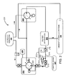
- FIG. 2 is a piping diagram of a hydraulic plant 200 according to one embodiment.
- the hydraulic plant 200 is operative to counter-rotate an engine driven hydraulic pump 202 to rotate the aircraft engine 100.
- the counter-rotation of the aircraft engine 100 may reduce the temperature differential between the top Y and the bottom X of the rotor 104.
- the hydraulic plant 200 is configured to supply hydraulic pressure through electrically powered hydraulic pump 204, through filter apparatus 206, and into engine driven hydraulic pump 202.
- the rotation of the rotor 104 of the aircraft engine 100 rotates the engine driven hydraulic pump 202 in a first direction via linkage 228, as illustrated in FIG. 3 .
- the linkage 228 links, or places in mechanical communication, the rotor 104 to the engine driven hydraulic pump 202.
- the linkage 228 includes rotor gears 300 and pump gears 302.
- the rotor gears 300 rotate, which in turn rotate the pump gears 302.
- the rotation of the pump gears 302 rotates the pumping mechanism (not shown) of the engine driven hydraulic pump 202, increasing the pressure of the hydraulic plant 200 to pump hydraulic fluid in a first fluid direction from the engine driven hydraulic pump 202 to provide hydraulic power to the aircraft.
- linkage 228, including the rotor gears 300 and the pump gears 302 are for purposes of description only.
- the presently disclosed subject matter is not limited in any manner to a linkage with the same or similar configuration as the linkage 228, as other types of gear mechanisms, number of gears, etc. may be used depending on the particular application.
- the engine driven hydraulic pump 202 rotates in a first direction to draw hydraulic fluid from a hydraulic reservoir 208 and supplies hydraulic fluid to aircraft hydraulic systems 210 in the first fluid direction.
- the aircraft hydraulic systems 210 may vary according to the particular configuration of the aircraft, but may include flight control systems, landing gear systems, and the like.
- the engine driven hydraulic pump 202 provides the hydraulic fluid through the filter apparatus 206 by way of hydraulic line 218 and out through the filter apparatus 206 to the aircraft hydraulic systems 210.
- a filter check valve 214 is situated at an inlet/outlet 216 of the filter apparatus 206.
- the check valve 214 may, in some configurations, be used to provide for a proper fluid pressurization path from the engine driven hydraulic pump 202 to the aircraft hydraulic systems 210 in the first fluid direction. In some configurations, if the check valve 214 was not present, hydraulic pressure may enter the filter apparatus 206 in the incorrect direction, possibly causing a backflow of fluid within the hydraulic plant 200, which may cause damage to some of the aircraft hydraulic systems 210.
- the electrically powered hydraulic pump 204 may be used to rotate the engine driven hydraulic pump 202 in a second direction as a hydraulic motor by providing hydraulic fluid to the engine driven hydraulic pump 202 in a second fluid direction.
- the second direction of the engine driven hydraulic pump 202 when driven by the electrically powered hydraulic pump 204, is opposite to the direction of the engine driven hydraulic pump 202 when driven by the rotor 104. Because in some configurations the gears 300 of the rotor 104 remain engaged with the gears 302 of the engine, rotating the engine driven hydraulic pump 202 will cause the rotation of the rotor 104.
- the electrically powered hydraulic pump 204 may be engaged to pressurize a hydraulic line 218, which is the outlet of the engine driven hydraulic pump 202. Pressurizing the hydraulic line 218 may unseat the engine driven hydraulic pump check valve 220, forcing the rotation of the engine driven hydraulic pump 202, and in turn, forcing the rotation of the rotor 104.
- the check valve 214 prevents the pressurization of the hydraulic line 218.
- the hydraulic plant 200 may include a solenoid-operated bypass valve 222 to bypass hydraulic fluid around the check valve 214, facilitating the pressurization of the hydraulic line 218.
- the solenoid-operated bypass valve 222 may receive a control signal 224 at valve solenoid control 226.
- a control signal may be an electrical signal that energizes the solenoid-operated bypass valve 222, thus opening the solenoid-operated bypass valve 222 as the solenoid-operated bypass valve 222 is an energize-to-open type of valve.
- the solenoid-operated bypass valve 222 when energized, is operative to fluidically connect the electrically powered hydraulic pump 204 to the engine driven hydraulic pump 202, whereby the electrically powered hydraulic pump 204 provides hydraulic pressure to rotate the engine driven hydraulic pump 202, which in turn rotates the rotor 104.
- the check valve 214 when shut, the check valve 214 fluidically disconnects the electrically powered hydraulic pump 204 from the engine driven hydraulic pump 202.
- the solenoid-operated bypass valve 222 routes hydraulic fluid around the check valve 214.
- the solenoid-operated bypass valve 222 is de-energized, the engine driven hydraulic pump 202 is fluidically disconnected from the electrically powered hydraulic pump 204, thereby stopping the rotation of the rotor 104.
- the control signal 224 may be generated using various parameters associated with a rotor of an aircraft engine. For example, one parameter may be an amount of time. The control signal 224 may be based on an amount of time determined to a time suitable to reduce the warpage of the rotor 104. When the time expires, the control signal 224 may be used to close the solenoid-operated bypass valve 222, thus preventing the pressurization of the hydraulic line 218, ceasing the rotation of the rotor 104 because of the ceased rotation of the engine driven hydraulic pump 202.
- the control signal 224 may also be generated in response to other parameters such as temperature, degree of warpage, and whether or not the aircraft engine is stopped.
- the control signal 224 may be based on an input from a control system that monitors various conditions of the aircraft engine 100 or other systems of an aircraft.
- the rotor 104 may have warpage detectors that sense the amount of warpage the rotor 104 is experiencing. Above a certain warpage level, the control signal 224 may be activated, causing the rotation of the rotor 104.
- the rotor 104 may have temperature sensors. Above a certain temperature differential across the temperature sensors, the control signal 224 may be activated, causing the rotation of the rotor 104. When the temperature differential decreases below a certain amount, the control signal 224 may be removed. It should be understood that these parameters are examples of parameters and do not constitute an exhaustive list, as other parameters may be used and are considered to be within the scope of the present disclosure.
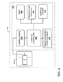
- FIG. 4 is an illustration of a control system 400 that may be used to provide the control signal 224 to rotate the engine driven hydraulic pump 202.
- the control system 400 may include a control circuit 402 and the solenoid-operated bypass valve 222.
- the control circuit 402 may include a warpage controller 404 operative to receive an input and, depending on the input, output the control signal 224 to open or close the solenoid-operated bypass valve 222.
- the inputs to the warpage controller 404 may come from various sources, including, but not limited to, a timer 406, temperature sensor(s) 408, and a warpage sensor 410.
- the timer 406 may be used to provide a time input to the warpage controller 404.
- the time may be used by the warpage controller 404 to determine a period a time in which the rotor 104 should be rotated.
- the temperature sensor(s) 408 may be an input from one or more temperature sensors located on the rotor 104 or other areas, including other components of the aircraft engine 100.
- the warpage sensor 410 may be an input reflecting an amount of warpage (or bending) the rotor 104 is experiencing.
- the control circuit 402 may also include an engine operating condition input 412.
- the engine operating condition input 412 may be a signal provided to the control circuit 402 that provides information that an aircraft engine is stopped. As used herein, "stopped mode" means that the aircraft engine is no longer producing power. In some configurations, the aircraft engine 100 is stopped when the aircraft engine 100 has completely stopped rotating. In other configurations, the aircraft engine 100 is considered stopped when the aircraft engine 100 is not producing power. These and other configurations are considered to be within the scope of the present disclosure.
- the engine operating condition input 412 may be used as an interlock to reduce the probability that the electrically power hydraulic pump 204 attempts to rotate the rotor 104 while the rotor 104 is being rotated by the aircraft engine 100 while the aircraft engine 100 is producing power.
- FIG. 5 illustrates one configuration of a routine 500 for reducing the warpage of the rotor 104 according to at least one embodiment disclosed herein. Unless otherwise indicated, more or fewer operations may be performed than shown in the figures and described herein. Additionally, unless otherwise indicated, these operations may also be performed in a different order than those described herein.
- the routine 500 commences at operation 502, where the engine operating condition input 412 is received, indicating that the aircraft engine is in stopped mode.
- the engine operating condition input 412 may be used to reduce the likelihood that the engine driven hydraulic pump 202 receives hydraulic pressure from the electrically powered hydraulic pump 204, possibly causing the engine driven hydraulic pump 202 to impart a counter-rotational force against the rotor 104.
- the routine 500 continues to operation 504, where the electrically powered hydraulic pump 204 is energized.
- the electrically powered hydraulic pump 204 When in fluidic communication with the engine driven hydraulic pump 202, the electrically powered hydraulic pump 204 provides hydraulic fluid flow (pressure) in a direction opposite to the direction normally provided by the engine driven hydraulic pump 202.
- the engine driven hydraulic pump 202 rotates in a first rotational direction caused by the mechanical linkage 228 with the rotor 104.
- the rotating action of the rotor 104 rotates the engine driven hydraulic pump 202.
- the opposite direction of the fluid flow (or pressure) causes the engine driven hydraulic pump 202 to rotate in the opposite direction.
- the rotation of the engine driven hydraulic pump 202 imparts a rotational force on the rotor 104, causing the rotor 104 to rotate.
- the routine 500 continues to operation 506, where a solenoid-operated valve is energized.
- a solenoid-operated valve is energized.
- the filter apparatus 206 can have the check valve 214 that is operative to prevent fluid flow in a direction opposite to the normal, operational direction when the aircraft engine is operating.
- the check valve 214 can prevent fluid flow from the electrically powered hydraulic pump 204 thru the filter apparatus 206 in a different direction than normally supplied by the engine driven hydraulic pump 202.
- the solenoid-operated bypass valve 222 can be energized to allow fluid flow through the filter apparatus 206.
- the increase in pressure can cause the engine driven hydraulic pump 202 to rotate.
- the pressure may be maintained at the engine driven hydraulic pump 202 to provide a "constant-on" mode of operation, whereby the engine driven hydraulic pump 202 is constantly rotated.
- the pressure provided by the electrically powered hydraulic pump 204 may be pulsed by intermittently opening and closing the solenoid-operated bypass valve 222.
- the pulsing of the pressure may be termed a "pulsed mode of operation.”
- the routine 500 continues to operation 508, where the solenoid-operated bypass valve 222 is de-energized and closed, ceasing the rotation of the engine driven hydraulic pump 202.
- a hydraulic plant operative to reduce rotor warpage
- the hydraulic system comprising an engine driven hydraulic pump operative to receive a rotational force in a first direction from an engine rotor to supply hydraulic pressure to a hydraulic system in a first fluid direction; a filter apparatus operative to filter hydraulic fluid received from the engine driven hydraulic pump in the first fluid direction, the filter apparatus comprising a filter check valve to allow fluid flow in the first fluid direction and prevent fluid flow in a second direction; a hydraulic pump operative to provide hydraulic fluid to the engine driven hydraulic pump in the second fluid direction; and a bypass valve operative to bypass the filter check valve to allow hydraulic fluid flow in the second fluid direction to cause the engine driven hydraulic pump to rotate in a second direction to cause the aircraft engine to rotate.
- bypass valve is a solenoid-operated bypass valve.
- bypass valve comprises a valve solenoid control operative to open or close the bypass valve based on a control signal.
- control signal is received from a warpage controller operative to receive at least one input to cause the opening or closing of the bypass valve.
- the hydraulic plant described herein wherein the at least one input comprises an input from a timer, a temperature sensor or a warpage sensor.
- bypass valve is opened and closed intermittently to provide for a pulsed mode of operation.
- a control system operative to reduce rotor warpage
- the control circuit comprising a control circuit comprising; a warpage controller operative to receive an input relating to a parameter associated with a rotor of an aircraft engine and, in response to the input, output a control signal operative to open or close a bypass valve in a hydraulic system, and a sensor operative to generate the input relating to the parameter associated with a rotor of an aircraft engine; and the bypass valve operative to fluidically connect an electric hydraulic pump to an engine driven hydraulic pump, whereby the electric hydraulic pump provides hydraulic pressure to rotate the engine driven hydraulic pump, which in turn is operative to rotate the rotor of the aircraft engine.
- the control system described herein wherein the input comprises a time, a temperature or a degree of warpage.
- bypass valve is a solenoid-operated bypass valve.
- bypass valve comprises a valve solenoid control operative to open or close the bypass valve based on the control signal.
- control system described herein wherein the control signal is received from a warpage controller operative to receive at least one input to cause the opening or closing of the bypass valve.
- the at least one input comprises an input from a timer, a temperature sensor or a warpage sensor.
- bypass valve is opened and closed intermittently to provide for a pulsed mode of operation.
- bypass valve remains open to provide a constant-on mode of operation.
- a method for reducing aircraft engine rotor warpage comprising rotating an engine driven hydraulic pump in a first direction, wherein the engine driven hydraulic pump is linked to a rotor, to provide hydraulic fluid in a first fluid direction from the engine driven hydraulic pump to a hydraulic system; receiving an input that the aircraft engine is stopped; energizing an electric hydraulic pump to provide hydraulic flow in a second fluid direction; energizing a solenoid-operated bypass valve; in response to energizing the solenoid-operated bypass valve, routing hydraulic fluid around a filter check valve, the filter check valve configured to prevent hydraulic flow in the second fluid direction and allow hydraulic flow in the first fluid direction, wherein the first fluid direction of the hydraulic flow is a normal direction of fluid flow when the aircraft engine is rotating; causing the engine driven hydraulic pump to rotate in a second direction due to the hydraulic flow in the second fluid direction, wherein the second direction is opposite to the first direction in which the engine driven hydraulic pump rotates while the aircraft engine is operating
- the method disclosed herein further comprising receiving an input to de-energize the solenoid.
- the input comprises a time, a temperature or a degree of warpage.
Landscapes
- Engineering & Computer Science (AREA)
- Mechanical Engineering (AREA)
- General Engineering & Computer Science (AREA)
- Chemical & Material Sciences (AREA)
- Combustion & Propulsion (AREA)
- Fluid-Pressure Circuits (AREA)
Abstract
Description
- During normal operation, the temperature of an aircraft engine's main shaft (rotor) will reach an equilibrium operating temperature. In most instances, the temperature will be significantly greater than the air surrounding the engine due to the effects of air compression and combustion in the engine. Once the engine is shut down, or stopped, the rotor will typically start cooling down because of the lower temperatures in the environment surrounding the engine. If the cooling of the rotor is uneven, the rotor may become unbalanced, possibly leading to damage when the engine is placed back into service.
- It is with respect to these and other considerations that the disclosure herein is presented.
- It should be appreciated that this Summary is provided to introduce a selection of concepts in a simplified form that are further described below in the Detailed Description. This Summary is not intended to be used to limit the scope of the claimed subject matter.
- According to one embodiment disclosed herein, a hydraulic system operative to reduce rotor warpage is provided. The hydraulic system includes an engine driven hydraulic pump, a filter apparatus, a hydraulic pump, and a bypass valve. The engine driven hydraulic pump is operative to receive a rotational force in a first direction from an engine rotor to supply hydraulic pressure to the hydraulic system in a first fluid direction. The filter apparatus is operative to filter hydraulic fluid received from the engine driven hydraulic pump in the first fluid direction, the filter apparatus comprising a filter check valve to allow fluid flow in the first fluid direction and prevent fluid flow in a second direction. The hydraulic pump is operative to provide hydraulic fluid to the engine driven hydraulic pump in the second fluid direction. The bypass valve is operative to bypass the filter check valve to allow hydraulic fluid flow in the second direction to cause the engine driven hydraulic pump to rotate in a second rotational direction to cause the aircraft engine to rotate.
- According to another embodiment disclosed herein, a control system operative to reduce rotor warpage is provided. The control system includes a control circuit and a bypass valve. The control circuit includes a warpage controller and a sensor. The warpage controller is operative to receive an input relating to a parameter associated with a rotor of an aircraft engine and, in response to the input, output a control signal operative to open or close a bypass valve in a hydraulic system. The sensor is operative to generate the input relating to the parameter associated with a rotor of an aircraft engine. The bypass valve is operative to fluidically connect an electric hydraulic pump to an engine driven hydraulic pump, whereby the electric hydraulic pump provides hydraulic pressure to rotate the engine driven hydraulic pump in a second direction as a hydraulic motor, which in turn is operative to rotate the rotor of the aircraft engine
- According to yet another embodiment disclosed herein, a method for reducing aircraft engine rotor warpage is provided. The method includes rotating an engine driven hydraulic pump in a first direction, wherein the engine driven hydraulic pump is linked to a rotor, to provide hydraulic fluid in a first fluid direction from the engine driven hydraulic pump to a hydraulic system, receiving an input that an aircraft engine is stopped, energizing an electric hydraulic pump to provide hydraulic flow in a first direction, energizing a solenoid-operated bypass valve, in response to energizing the solenoid-operated bypass valve, routing hydraulic fluid around a filter check valve, the filter check valve configured to prevent hydraulic flow in the first direction and allow hydraulic flow in a second direction, wherein the second direction of the hydraulic flow is a normal direction of fluid flow when the aircraft engine is operating, causing an engine driven hydraulic pump to rotate in a first rotational direction due to the hydraulic flow in the first direction, wherein the first rotational direction is opposite to a second rotational direction in which the engine driven hydraulic pump rotates while the aircraft engine is operating, de-energizing the solenoid-operated bypass valve, and in response to de-energizing the solenoid-operated bypass valve, fluidically disconnecting the engine driven hydraulic pump from the electric hydraulic pump, stopping the rotation of the engine driven hydraulic pump.
- The features, functions, and advantages that have been discussed can be achieved independently in various embodiments of the present disclosure or may be combined in yet other embodiments, further details of which can be seen with reference to the following description and drawings.
- The embodiments presented herein will become more fully understood from the detailed description and the accompanying drawings, wherein:
-
FIG. 1 is a perspective view illustrating a partial aircraft engine according to at least one embodiment disclosed herein. -
FIG. 2 is a piping diagram of a hydraulic plant operative to counter-rotate an engine driven pump according to at least one embodiment disclosed herein. -
FIG. 3 is front view of the gears of an engine driven pump and an engine rotor according to at least one embodiment disclosed herein. -
FIG. 4 is an illustration of a control system according to at least one embodiment disclosed herein. -
FIG. 5 illustrates one configuration of a routine for reducing the warpage of an aircraft engine rotor according to at least one embodiment disclosed herein. - The plurality of figures presented in this application illustrates variations and different aspects of the embodiments of the present disclosure. Accordingly, the detailed description on each illustration will describe the differences identified in the corresponding illustration.
- The following detailed description is directed to an apparatus, system, and method for controlling the cool down of an aircraft engine rotor. After an aircraft engine is shutdown, the rotor of the aircraft engine (along with other components) begins to cool down from a relatively high operational temperature to a relatively low ambient (or off) temperature. The rotor and other engine components commence a heat exchange operation with outside air. The rate of cool down may vary depending on the heat transfer coefficient of the metal/composites forming the aircraft engine and the temperature of the air surrounding the rotor and components. In some situations, the temperature of some parts of the engine may experience different heat transfer rates depending on their location in the engine. This is illustrated by way of example in
FIG. 1 . -
FIG. 1 is a perspective view illustrating a partially constructedaircraft engine 100. Theaircraft engine 100 includes a cowling 102 and arotor 104. Thecowling 102 has anintake portion 106 that allows air to enter theaircraft engine 100. Thecowling 102 also has anexhaust portion 108 that allows combusted fluids to exit theaircraft engine 100. - During operation, various components of the
aircraft engine 100 will increase in temperature. Therotor 104, which rotates during normal operation, will typically have a temperature that is significantly greater than the surroundings. Various components (not shown) of theaircraft engine 100 are affixed to therotor 104 during operation, including fan blades. - After operation, the
aircraft engine 100 may be stopped and allowed to cool. Because heat rises, for example from location A to location B of line AB, a temperature differential may form across theaircraft engine 100. This temperature differential may cause certain components to have different temperatures at different locations. For example, the bottom X of therotor 104 may have a lower temperature than the top Y of therotor 104. The temperature differential may be relatively significant if the temperature of the environment at the bottom X of therotor 104 is significantly lower than the temperature of the top Y of therotor 104. - Warping of the
rotor 104 may result if the temperature differential between the bottom X of therotor 104 and the top Y of therotor 104 is significant. Because the length of metals typically increases or decreases based on the temperature of the metal, caused by expansion and contraction, the length of therotor 104 at the top Y may be greater than the length of therotor 104 at the bottom X. Because therotor 104 is typically a unitary metal or metallic alloy, the difference in lengths can cause therotor 104 to warp or bend. - Over a period of time, if the
rotor 104 is allowed to cool sufficiently, the temperature differential between the top Y and the bottom X of therotor 104 will begin to decrease, eventually approaching equivalent temperatures. As the temperature differential decreases, the lengths of therotor 104 at the top Y and the bottom X begin to even, thus reducing the amount of warpage. - If the
rotor 104 is not allowed to cool for a sufficient period of time, thus suffering from a particular degree of warpage caused by the temperature differential, and theaircraft engine 100 is placed back into service, the warpage of therotor 104 may cause damage to the engine. During operation, therotor 104 may rotate at a relatively high speed of rotation, sometimes on the order of several thousands of rotations per minute. If therotor 104 is not balanced, the rotation of therotor 104 may generate vibrations in theaircraft engine 100. When therotor 104 is warped to a particular degree, the warpage may cause therotor 104 to be out of balance. The vibrations can shake theaircraft engine 100 significantly, leading to operational inconsistencies or operation at less than optimal conditions. Thus, when theaircraft engine 100 is stopped, it may be preferable to slowly rotate therotor 104 during shutdown time to reduce, or eliminate, the temperature differential between the top Y and the bottom X of therotor 104. -
FIG. 2 is a piping diagram of ahydraulic plant 200 according to one embodiment. Thehydraulic plant 200 is operative to counter-rotate an engine drivenhydraulic pump 202 to rotate theaircraft engine 100. The counter-rotation of theaircraft engine 100 may reduce the temperature differential between the top Y and the bottom X of therotor 104. In order to counter-rotate theaircraft engine 100, thehydraulic plant 200 is configured to supply hydraulic pressure through electrically poweredhydraulic pump 204, through filter apparatus 206, and into engine drivenhydraulic pump 202. - During a typical operation, the rotation of the
rotor 104 of theaircraft engine 100 rotates the engine drivenhydraulic pump 202 in a first direction vialinkage 228, as illustrated inFIG. 3 . Thelinkage 228 links, or places in mechanical communication, therotor 104 to the engine drivenhydraulic pump 202. InFIG. 3 , thelinkage 228 includes rotor gears 300 and pump gears 302. When therotor 104 rotates, the rotor gears 300 rotate, which in turn rotate the pump gears 302. The rotation of the pump gears 302 rotates the pumping mechanism (not shown) of the engine drivenhydraulic pump 202, increasing the pressure of thehydraulic plant 200 to pump hydraulic fluid in a first fluid direction from the engine drivenhydraulic pump 202 to provide hydraulic power to the aircraft. It should be understood that the illustration and accompanying description of thelinkage 228, including the rotor gears 300 and the pump gears 302, are for purposes of description only. The presently disclosed subject matter is not limited in any manner to a linkage with the same or similar configuration as thelinkage 228, as other types of gear mechanisms, number of gears, etc. may be used depending on the particular application. - Returning to
FIG. 2 , while therotor 104 of theaircraft engine 100 rotates, the engine drivenhydraulic pump 202 rotates in a first direction to draw hydraulic fluid from ahydraulic reservoir 208 and supplies hydraulic fluid to aircrafthydraulic systems 210 in the first fluid direction. The aircrafthydraulic systems 210 may vary according to the particular configuration of the aircraft, but may include flight control systems, landing gear systems, and the like. The engine drivenhydraulic pump 202 provides the hydraulic fluid through the filter apparatus 206 by way ofhydraulic line 218 and out through the filter apparatus 206 to the aircrafthydraulic systems 210. - In some configurations, to prevent backflow through the filter apparatus 206, a
filter check valve 214 is situated at an inlet/outlet 216 of the filter apparatus 206. Thecheck valve 214 may, in some configurations, be used to provide for a proper fluid pressurization path from the engine drivenhydraulic pump 202 to the aircrafthydraulic systems 210 in the first fluid direction. In some configurations, if thecheck valve 214 was not present, hydraulic pressure may enter the filter apparatus 206 in the incorrect direction, possibly causing a backflow of fluid within thehydraulic plant 200, which may cause damage to some of the aircrafthydraulic systems 210. - When the
aircraft engine 100 is stopped, therotor 104 of theaircraft engine 100 no longer provides the rotational motion to rotate the engine drivenhydraulic pump 202. In most circumstances, therotor 104 also begins to cool. To reduce the likelihood that therotor 104 experiences an undesirable degree of warpage, the electrically poweredhydraulic pump 204 may be used to rotate the engine drivenhydraulic pump 202 in a second direction as a hydraulic motor by providing hydraulic fluid to the engine drivenhydraulic pump 202 in a second fluid direction. The second direction of the engine drivenhydraulic pump 202, when driven by the electrically poweredhydraulic pump 204, is opposite to the direction of the engine drivenhydraulic pump 202 when driven by therotor 104. Because in some configurations thegears 300 of therotor 104 remain engaged with thegears 302 of the engine, rotating the engine drivenhydraulic pump 202 will cause the rotation of therotor 104. - Thus, in some configurations, after or at a proximate time to shutting down the
aircraft engine 100, the electrically poweredhydraulic pump 204 may be engaged to pressurize ahydraulic line 218, which is the outlet of the engine drivenhydraulic pump 202. Pressurizing thehydraulic line 218 may unseat the engine driven hydraulicpump check valve 220, forcing the rotation of the engine drivenhydraulic pump 202, and in turn, forcing the rotation of therotor 104. - But, in some configurations, the
check valve 214 prevents the pressurization of thehydraulic line 218. Thus, thehydraulic plant 200 may include a solenoid-operatedbypass valve 222 to bypass hydraulic fluid around thecheck valve 214, facilitating the pressurization of thehydraulic line 218. The solenoid-operatedbypass valve 222 may receive acontrol signal 224 atvalve solenoid control 226. A control signal may be an electrical signal that energizes the solenoid-operatedbypass valve 222, thus opening the solenoid-operatedbypass valve 222 as the solenoid-operatedbypass valve 222 is an energize-to-open type of valve. - Thus, in one configuration, when energized, the solenoid-operated
bypass valve 222 is operative to fluidically connect the electrically poweredhydraulic pump 204 to the engine drivenhydraulic pump 202, whereby the electrically poweredhydraulic pump 204 provides hydraulic pressure to rotate the engine drivenhydraulic pump 202, which in turn rotates therotor 104. - In another configuration, when shut, the
check valve 214 fluidically disconnects the electrically poweredhydraulic pump 204 from the engine drivenhydraulic pump 202. When fluidically connected, the solenoid-operatedbypass valve 222 routes hydraulic fluid around thecheck valve 214. When the solenoid-operatedbypass valve 222 is de-energized, the engine drivenhydraulic pump 202 is fluidically disconnected from the electrically poweredhydraulic pump 204, thereby stopping the rotation of therotor 104. - The
control signal 224 may be generated using various parameters associated with a rotor of an aircraft engine. For example, one parameter may be an amount of time. Thecontrol signal 224 may be based on an amount of time determined to a time suitable to reduce the warpage of therotor 104. When the time expires, thecontrol signal 224 may be used to close the solenoid-operatedbypass valve 222, thus preventing the pressurization of thehydraulic line 218, ceasing the rotation of therotor 104 because of the ceased rotation of the engine drivenhydraulic pump 202. - The
control signal 224 may also be generated in response to other parameters such as temperature, degree of warpage, and whether or not the aircraft engine is stopped. For example, thecontrol signal 224 may be based on an input from a control system that monitors various conditions of theaircraft engine 100 or other systems of an aircraft. Therotor 104 may have warpage detectors that sense the amount of warpage therotor 104 is experiencing. Above a certain warpage level, thecontrol signal 224 may be activated, causing the rotation of therotor 104. In another example, therotor 104 may have temperature sensors. Above a certain temperature differential across the temperature sensors, thecontrol signal 224 may be activated, causing the rotation of therotor 104. When the temperature differential decreases below a certain amount, thecontrol signal 224 may be removed. It should be understood that these parameters are examples of parameters and do not constitute an exhaustive list, as other parameters may be used and are considered to be within the scope of the present disclosure. -
FIG. 4 is an illustration of acontrol system 400 that may be used to provide thecontrol signal 224 to rotate the engine drivenhydraulic pump 202. Thecontrol system 400 may include acontrol circuit 402 and the solenoid-operatedbypass valve 222. Thecontrol circuit 402 may include awarpage controller 404 operative to receive an input and, depending on the input, output thecontrol signal 224 to open or close the solenoid-operatedbypass valve 222. The inputs to thewarpage controller 404 may come from various sources, including, but not limited to, atimer 406, temperature sensor(s) 408, and awarpage sensor 410. - The
timer 406 may be used to provide a time input to thewarpage controller 404. The time may be used by thewarpage controller 404 to determine a period a time in which therotor 104 should be rotated. The temperature sensor(s) 408 may be an input from one or more temperature sensors located on therotor 104 or other areas, including other components of theaircraft engine 100. Thewarpage sensor 410 may be an input reflecting an amount of warpage (or bending) therotor 104 is experiencing. - The
control circuit 402 may also include an engineoperating condition input 412. The engineoperating condition input 412 may be a signal provided to thecontrol circuit 402 that provides information that an aircraft engine is stopped. As used herein, "stopped mode" means that the aircraft engine is no longer producing power. In some configurations, theaircraft engine 100 is stopped when theaircraft engine 100 has completely stopped rotating. In other configurations, theaircraft engine 100 is considered stopped when theaircraft engine 100 is not producing power. These and other configurations are considered to be within the scope of the present disclosure. In some examples, the engineoperating condition input 412 may be used as an interlock to reduce the probability that the electrically powerhydraulic pump 204 attempts to rotate therotor 104 while therotor 104 is being rotated by theaircraft engine 100 while theaircraft engine 100 is producing power. -
FIG. 5 illustrates one configuration of a routine 500 for reducing the warpage of therotor 104 according to at least one embodiment disclosed herein. Unless otherwise indicated, more or fewer operations may be performed than shown in the figures and described herein. Additionally, unless otherwise indicated, these operations may also be performed in a different order than those described herein. - The routine 500 commences at
operation 502, where the engineoperating condition input 412 is received, indicating that the aircraft engine is in stopped mode. As discussed briefly above, the engineoperating condition input 412 may be used to reduce the likelihood that the engine drivenhydraulic pump 202 receives hydraulic pressure from the electrically poweredhydraulic pump 204, possibly causing the engine drivenhydraulic pump 202 to impart a counter-rotational force against therotor 104. - The routine 500 continues to
operation 504, where the electrically poweredhydraulic pump 204 is energized. When in fluidic communication with the engine drivenhydraulic pump 202, the electrically poweredhydraulic pump 204 provides hydraulic fluid flow (pressure) in a direction opposite to the direction normally provided by the engine drivenhydraulic pump 202. During operation, the engine drivenhydraulic pump 202 rotates in a first rotational direction caused by themechanical linkage 228 with therotor 104. The rotating action of therotor 104 rotates the engine drivenhydraulic pump 202. As discussed above inFIG. 1 , the opposite direction of the fluid flow (or pressure) causes the engine drivenhydraulic pump 202 to rotate in the opposite direction. Because of themechanical linkage 228 with therotor 104, the rotation of the engine drivenhydraulic pump 202 imparts a rotational force on therotor 104, causing therotor 104 to rotate. - The routine 500 continues to
operation 506, where a solenoid-operated valve is energized. In some configurations of a hydraulic system, such as the configuration illustrated inFIG. 2 , the filter apparatus 206 can have thecheck valve 214 that is operative to prevent fluid flow in a direction opposite to the normal, operational direction when the aircraft engine is operating. - The
check valve 214 can prevent fluid flow from the electrically poweredhydraulic pump 204 thru the filter apparatus 206 in a different direction than normally supplied by the engine drivenhydraulic pump 202. The solenoid-operatedbypass valve 222 can be energized to allow fluid flow through the filter apparatus 206. - Depending on the pressure provided by the electrically powered
hydraulic pump 204, the increase in pressure can cause the engine drivenhydraulic pump 202 to rotate. In some configurations, the pressure may be maintained at the engine drivenhydraulic pump 202 to provide a "constant-on" mode of operation, whereby the engine drivenhydraulic pump 202 is constantly rotated. In another configuration, the pressure provided by the electrically poweredhydraulic pump 204 may be pulsed by intermittently opening and closing the solenoid-operatedbypass valve 222. In some configurations, the pulsing of the pressure may be termed a "pulsed mode of operation." The routine 500 continues tooperation 508, where the solenoid-operatedbypass valve 222 is de-energized and closed, ceasing the rotation of the engine drivenhydraulic pump 202. - According to an aspect of the present disclosure there is provided a hydraulic plant operative to reduce rotor warpage, the hydraulic system comprising an engine driven hydraulic pump operative to receive a rotational force in a first direction from an engine rotor to supply hydraulic pressure to a hydraulic system in a first fluid direction; a filter apparatus operative to filter hydraulic fluid received from the engine driven hydraulic pump in the first fluid direction, the filter apparatus comprising a filter check valve to allow fluid flow in the first fluid direction and prevent fluid flow in a second direction; a hydraulic pump operative to provide hydraulic fluid to the engine driven hydraulic pump in the second fluid direction; and a bypass valve operative to bypass the filter check valve to allow hydraulic fluid flow in the second fluid direction to cause the engine driven hydraulic pump to rotate in a second direction to cause the aircraft engine to rotate.
- The hydraulic plant described herein wherein the bypass valve is a solenoid-operated bypass valve.
- The hydraulic plant described herein wherein the bypass valve comprises a valve solenoid control operative to open or close the bypass valve based on a control signal.
- The hydraulic plant described herein wherein the control signal is received from a warpage controller operative to receive at least one input to cause the opening or closing of the bypass valve.
- The hydraulic plant described herein wherein the at least one input comprises an input from a timer, a temperature sensor or a warpage sensor.
- The hydraulic plant described herein wherein the bypass valve is opened and closed intermittently to provide for a pulsed mode of operation.
- The hydraulic plant described herein wherein the bypass valve remains open to provide a constant-on mode of operation.
- The hydraulic plant described herein wherein the hydraulic pump is electric current-powered.
- According to a further aspect of the present disclosure there is provided a control system operative to reduce rotor warpage, the control circuit comprising a control circuit comprising; a warpage controller operative to receive an input relating to a parameter associated with a rotor of an aircraft engine and, in response to the input, output a control signal operative to open or close a bypass valve in a hydraulic system, and a sensor operative to generate the input relating to the parameter associated with a rotor of an aircraft engine; and the bypass valve operative to fluidically connect an electric hydraulic pump to an engine driven hydraulic pump, whereby the electric hydraulic pump provides hydraulic pressure to rotate the engine driven hydraulic pump, which in turn is operative to rotate the rotor of the aircraft engine.
- The control system described herein wherein the input comprises a time, a temperature or a degree of warpage.
- The control system described herein wherein the bypass valve is a solenoid-operated bypass valve.
- The control system described herein wherein the bypass valve comprises a valve solenoid control operative to open or close the bypass valve based on the control signal.
- The control system described herein wherein the control signal is received from a warpage controller operative to receive at least one input to cause the opening or closing of the bypass valve.
- The control system described herein wherein the at least one input comprises an input from a timer, a temperature sensor or a warpage sensor.
- The control system described herein wherein the bypass valve is opened and closed intermittently to provide for a pulsed mode of operation.
- The control system described herein wherein the bypass valve remains open to provide a constant-on mode of operation.
- The control system described herein wherein the electric hydraulic pump is alternating current-powered.
- According to a further aspect of the present disclosure there is provided a method for reducing aircraft engine rotor warpage, the method comprising rotating an engine driven hydraulic pump in a first direction, wherein the engine driven hydraulic pump is linked to a rotor, to provide hydraulic fluid in a first fluid direction from the engine driven hydraulic pump to a hydraulic system; receiving an input that the aircraft engine is stopped; energizing an electric hydraulic pump to provide hydraulic flow in a second fluid direction; energizing a solenoid-operated bypass valve; in response to energizing the solenoid-operated bypass valve, routing hydraulic fluid around a filter check valve, the filter check valve configured to prevent hydraulic flow in the second fluid direction and allow hydraulic flow in the first fluid direction, wherein the first fluid direction of the hydraulic flow is a normal direction of fluid flow when the aircraft engine is rotating; causing the engine driven hydraulic pump to rotate in a second direction due to the hydraulic flow in the second fluid direction, wherein the second direction is opposite to the first direction in which the engine driven hydraulic pump rotates while the aircraft engine is operating; de-energizing the solenoid-operated bypass valve; and in response to de-energizing the solenoid-operated bypass valve, fluidically disconnecting the engine driven hydraulic pump from the electric hydraulic pump, stopping the rotation of the engine driven hydraulic pump.
- The method disclosed herein further comprising receiving an input to de-energize the solenoid.
- The method disclosed herein wherein the input comprises a time, a temperature or a degree of warpage.
- The subject matter described above is provided by way of illustration only and should not be construed as limiting. Various modifications and changes may be made to the subject matter described herein without following the example embodiments and applications illustrated and described, and without departing from the true spirit and scope of the present disclosure, which is set forth in the following claims.
Claims (11)
- A hydraulic plant (200) operative to reduce rotor warpage, the hydraulic system comprising:an engine driven hydraulic pump (202) operative to receive a rotational force in a first direction from an engine rotor to supply hydraulic pressure to a hydraulic system in a first fluid direction;a filter apparatus (206) operative to filter hydraulic fluid received from the engine driven hydraulic pump (202) in the first fluid direction, the filter apparatus (206) comprising a filter check valve (214) to allow fluid flow in the first fluid direction and prevent fluid flow in a second direction;a hydraulic pump (204) operative to provide hydraulic fluid to the engine driven hydraulic pump (202) in the second fluid direction; anda bypass valve (222) operative to bypass the filter check valve (214) to allow hydraulic fluid flow in the second fluid direction to cause the engine driven hydraulic pump (202) to rotate in a second direction to cause the aircraft engine to rotate.
- The hydraulic plant of claim 1, wherein the bypass valve (222) is a solenoid-operated bypass valve.
- The hydraulic plant of claim 2, wherein the bypass valve (222) comprises a valve solenoid control (226) operative to open or close the bypass valve based on a control signal (224).
- The hydraulic plant of claim 3, wherein the control signal (224) is received from a warpage controller (404) operative to receive at least one input (406, 408, 410) to cause the opening or closing of the bypass valve (222).
- The hydraulic plant of claim 4, wherein the at least one input comprises an input from a timer (406), a temperature sensor (408) or a warpage sensor (410).
- The hydraulic plant of any of claims 1 to 5, wherein the bypass valve (222) is opened and closed intermittently to provide for a pulsed mode of operation.
- The hydraulic plant of any of claims 1 to 6, wherein the bypass valve (222) remains open to provide a constant-on mode of operation.
- The hydraulic plant of any of claims 1 to 7, wherein the hydraulic pump (204) is electric current-powered.
- A method (500) for reducing aircraft engine rotor warpage, the method comprising:rotating an engine driven hydraulic pump (202) in a first direction, wherein the engine driven hydraulic pump is linked to a rotor, to provide hydraulic fluid in a first fluid direction from the engine driven hydraulic pump to a hydraulic system;receiving (502) an input that the aircraft engine is stopped;energizing (504) an electric hydraulic pump (204) to provide hydraulic flow in a second fluid direction;energizing (506) a solenoid-operated bypass valve;in response to energizing the solenoid-operated bypass valve (222), routing hydraulic fluid around a filter check valve (214), the filter check valve (214) configured to prevent hydraulic flow in the second fluid direction and allow hydraulic flow in the first fluid direction, wherein the first fluid direction of the hydraulic flow is a normal direction of fluid flow when the aircraft engine is rotating;causing the engine driven hydraulic pump (202) to rotate in a second direction due to the hydraulic flow in the second fluid direction, wherein the second direction is opposite to the first direction in which the engine driven hydraulic pump (202) rotates while the aircraft engine is operating;de-energizing (508) the solenoid-operated bypass valve (222); andin response to de-energizing the solenoid-operated bypass valve (222), fluidically disconnecting the engine driven hydraulic pump (202) from the electric hydraulic pump (204), stopping the rotation of the engine driven hydraulic pump (202).
- The method of claim 9, further comprising receiving an input (406, 408, 410) to de-energize the solenoid.
- The method of claim 10, wherein the input comprises a time (406), a temperature (408) or a degree of warpage (410).
Applications Claiming Priority (1)
| Application Number | Priority Date | Filing Date | Title |
|---|---|---|---|
| US14/180,868 US9771932B2 (en) | 2014-02-14 | 2014-02-14 | Apparatus, controller and method for controlling the cool down of an aircraft engine rotor |
Publications (2)
| Publication Number | Publication Date |
|---|---|
| EP2907979A1 true EP2907979A1 (en) | 2015-08-19 |
| EP2907979B1 EP2907979B1 (en) | 2017-07-05 |
Family
ID=51947110
Family Applications (1)
| Application Number | Title | Priority Date | Filing Date |
|---|---|---|---|
| EP14191022.4A Active EP2907979B1 (en) | 2014-02-14 | 2014-10-30 | Apparatus, controller and method for controlling the cool down of an aircraft engine rotor |
Country Status (2)
| Country | Link |
|---|---|
| US (1) | US9771932B2 (en) |
| EP (1) | EP2907979B1 (en) |
Citations (4)
| Publication number | Priority date | Publication date | Assignee | Title |
|---|---|---|---|---|
| US2440980A (en) * | 1946-04-23 | 1948-05-04 | Gen Electric | Turbine oil system with pump priming arrangement |
| US2602583A (en) * | 1949-05-06 | 1952-07-08 | Worthington Pump & Mach Corp | Lubrication means for service pump drive on compressors |
| GB1557706A (en) * | 1977-04-13 | 1979-12-12 | British Aircraft Corp Ltd | Aircraft hydraulic systems |
| FR2953562A1 (en) * | 2009-12-07 | 2011-06-10 | Snecma | Method for cooling equipment of aircraft, involves maintaining circulation of fluid in fluid circulation circuit of fluidic type equipment of aircraft until temperature decreases to predetermined value after stopping of turbojet engine |
Family Cites Families (17)
| Publication number | Priority date | Publication date | Assignee | Title |
|---|---|---|---|---|
| US3001360A (en) * | 1959-06-08 | 1961-09-26 | New York Air Brake Co | Engine starting system |
| US4062185A (en) * | 1976-05-13 | 1977-12-13 | General Electric Company | Method and apparatus for windmill starts in gas turbine engines |
| GB9313905D0 (en) * | 1993-07-06 | 1993-08-25 | Rolls Royce Plc | Shaft power transfer in gas turbine engines |
| US5845483A (en) * | 1996-04-10 | 1998-12-08 | General Electric Company | Windmill engine starting system with fluid driven motor and pump |
| US6237322B1 (en) * | 1999-06-21 | 2001-05-29 | Pratt & Whitney Canada Corp. | Oil pump |
| US6390116B1 (en) * | 2001-07-16 | 2002-05-21 | Illinois Institute Of Technology | Large amplitude pneumatic oscillator |
| US7975465B2 (en) * | 2003-10-27 | 2011-07-12 | United Technologies Corporation | Hybrid engine accessory power system |
| GB2411437B (en) * | 2004-02-28 | 2007-10-24 | Rolls Royce Plc | Aircraft gas turbine engines |
| WO2007043924A1 (en) * | 2005-10-14 | 2007-04-19 | Volvo Construction Equipment Ab | A working machine and a method for operating a working machine |
| US9121309B2 (en) * | 2006-06-10 | 2015-09-01 | Mtu Aero Engines Gmbh | Gas turbine and method of operating a gas turbine |
| US7942079B2 (en) * | 2007-02-16 | 2011-05-17 | Hamilton Sundstrand Corporation | Multi-speed gearbox for low spool driven auxiliary component |
| US7906866B2 (en) * | 2008-04-11 | 2011-03-15 | Honeywell International Inc. | AC/AC power converter for aircraft |
| US8146370B2 (en) * | 2008-05-21 | 2012-04-03 | Honeywell International Inc. | Turbine drive system with lock-up clutch and method |
| US8125164B2 (en) * | 2008-07-18 | 2012-02-28 | The Boeing Company | Parallel motor controller architecture |
| JP5073798B2 (en) * | 2010-08-31 | 2012-11-14 | 株式会社小松製作所 | forklift |
| US8515711B2 (en) * | 2010-10-21 | 2013-08-20 | Siemens Energy, Inc. | Diagnostic system and method for monitoring operating conditions of components of a turbine machine |
| US8813881B2 (en) * | 2012-05-04 | 2014-08-26 | Ford Global Technologies, Llc | Methods and systems for a vehicle driveline power take off |
-
2014
- 2014-02-14 US US14/180,868 patent/US9771932B2/en active Active
- 2014-10-30 EP EP14191022.4A patent/EP2907979B1/en active Active
Patent Citations (4)
| Publication number | Priority date | Publication date | Assignee | Title |
|---|---|---|---|---|
| US2440980A (en) * | 1946-04-23 | 1948-05-04 | Gen Electric | Turbine oil system with pump priming arrangement |
| US2602583A (en) * | 1949-05-06 | 1952-07-08 | Worthington Pump & Mach Corp | Lubrication means for service pump drive on compressors |
| GB1557706A (en) * | 1977-04-13 | 1979-12-12 | British Aircraft Corp Ltd | Aircraft hydraulic systems |
| FR2953562A1 (en) * | 2009-12-07 | 2011-06-10 | Snecma | Method for cooling equipment of aircraft, involves maintaining circulation of fluid in fluid circulation circuit of fluidic type equipment of aircraft until temperature decreases to predetermined value after stopping of turbojet engine |
Also Published As
| Publication number | Publication date |
|---|---|
| US9771932B2 (en) | 2017-09-26 |
| US20150233363A1 (en) | 2015-08-20 |
| EP2907979B1 (en) | 2017-07-05 |
Similar Documents
| Publication | Publication Date | Title |
|---|---|---|
| CN110446859B (en) | Equipment for adjusting hydraulic machines | |
| EP1944485B1 (en) | Fuel system for a gas turbine engine and operation method therefore | |
| US10480834B2 (en) | Refrigerant cooling and lubrication system | |
| CN102317599B (en) | Aeroengines having a mechanism for cooling electrical starting devices | |
| EP3530909B1 (en) | Fuel pump systems for turbomachines | |
| CN106124219B (en) | A kind of experimental rig and verification method for verifying lubricating oil pumping function after lubricating oil interrupts | |
| KR102293067B1 (en) | A method and a system for stopping a gas turbine, and a vehicle | |
| EP2039891A2 (en) | Electric motor driven lubrication supply system of a gas turbine and method | |
| CN110185775A (en) | The passive lubricating system of gas-turbine unit gear-box is used between the wind refunding | |
| EP2944812A1 (en) | Thermal energy recovery device and control method | |
| US10677095B2 (en) | Lubrication device for a turbine engine | |
| WO2021049454A1 (en) | Vacuum pump and vacuum pump system | |
| GB2555687A (en) | Aircraft fuel pump systems | |
| EP3712406B1 (en) | Backup system for demand fuel pumping system | |
| JP2013238224A (en) | System and method for heat recovery in gas turbine engine | |
| BR112014005840B1 (en) | METHOD OF TRACKING THE VOLUMETRIC EFFICIENCY OF A HIGH PRESSURE PUMP IN A HYDRAULIC REGULATOR SYSTEM OF A TURBOMACHINE | |
| CN105074354A (en) | Inlet guide vane mechanism | |
| CA2920612A1 (en) | Environmental control system utilizing parallel ram heat exchangers with air cycle machine speed compensation | |
| CN103423173A (en) | Temperature control system for a machine and method of operation thereof | |
| JP4702385B2 (en) | Fan control device | |
| EP2907979B1 (en) | Apparatus, controller and method for controlling the cool down of an aircraft engine rotor | |
| EP1467104B1 (en) | Compressor unit with assisted cooling | |
| US12535130B2 (en) | Gearbox arrangement providing partial vacuum within a gearbox device as well as method of efficiently providing and maintaining partial vacuum and use | |
| JP2016133199A (en) | Lubricating oil supply system of pump facility | |
| KR102002066B1 (en) | Improved Pumping Unit And Method For Controlling Such a Pumping Unit |
Legal Events
| Date | Code | Title | Description |
|---|---|---|---|
| PUAI | Public reference made under article 153(3) epc to a published international application that has entered the european phase |
Free format text: ORIGINAL CODE: 0009012 |
|
| AK | Designated contracting states |
Kind code of ref document: A1 Designated state(s): AL AT BE BG CH CY CZ DE DK EE ES FI FR GB GR HR HU IE IS IT LI LT LU LV MC MK MT NL NO PL PT RO RS SE SI SK SM TR |
|
| AX | Request for extension of the european patent |
Extension state: BA ME |
|
| 17P | Request for examination filed |
Effective date: 20160203 |
|
| RBV | Designated contracting states (corrected) |
Designated state(s): AL AT BE BG CH CY CZ DE DK EE ES FI FR GB GR HR HU IE IS IT LI LT LU LV MC MK MT NL NO PL PT RO RS SE SI SK SM TR |
|
| GRAP | Despatch of communication of intention to grant a patent |
Free format text: ORIGINAL CODE: EPIDOSNIGR1 |
|
| RIC1 | Information provided on ipc code assigned before grant |
Ipc: F01D 25/20 20060101AFI20160629BHEP Ipc: F02C 7/32 20060101ALI20160629BHEP Ipc: F01D 21/00 20060101ALI20160629BHEP |
|
| INTG | Intention to grant announced |
Effective date: 20160728 |
|
| GRAJ | Information related to disapproval of communication of intention to grant by the applicant or resumption of examination proceedings by the epo deleted |
Free format text: ORIGINAL CODE: EPIDOSDIGR1 |
|
| GRAP | Despatch of communication of intention to grant a patent |
Free format text: ORIGINAL CODE: EPIDOSNIGR1 |
|
| INTC | Intention to grant announced (deleted) | ||
| INTG | Intention to grant announced |
Effective date: 20170117 |
|
| GRAS | Grant fee paid |
Free format text: ORIGINAL CODE: EPIDOSNIGR3 |
|
| GRAA | (expected) grant |
Free format text: ORIGINAL CODE: 0009210 |
|
| AK | Designated contracting states |
Kind code of ref document: B1 Designated state(s): AL AT BE BG CH CY CZ DE DK EE ES FI FR GB GR HR HU IE IS IT LI LT LU LV MC MK MT NL NO PL PT RO RS SE SI SK SM TR |
|
| REG | Reference to a national code |
Ref country code: GB Ref legal event code: FG4D |
|
| REG | Reference to a national code |
Ref country code: CH Ref legal event code: EP |
|
| REG | Reference to a national code |
Ref country code: AT Ref legal event code: REF Ref document number: 906762 Country of ref document: AT Kind code of ref document: T Effective date: 20170715 |
|
| REG | Reference to a national code |
Ref country code: IE Ref legal event code: FG4D |
|
| REG | Reference to a national code |
Ref country code: DE Ref legal event code: R096 Ref document number: 602014011442 Country of ref document: DE |
|
| REG | Reference to a national code |
Ref country code: FR Ref legal event code: PLFP Year of fee payment: 4 |
|
| REG | Reference to a national code |
Ref country code: NL Ref legal event code: MP Effective date: 20170705 |
|
| REG | Reference to a national code |
Ref country code: AT Ref legal event code: MK05 Ref document number: 906762 Country of ref document: AT Kind code of ref document: T Effective date: 20170705 |
|
| REG | Reference to a national code |
Ref country code: LT Ref legal event code: MG4D |
|
| PG25 | Lapsed in a contracting state [announced via postgrant information from national office to epo] |
Ref country code: NO Free format text: LAPSE BECAUSE OF FAILURE TO SUBMIT A TRANSLATION OF THE DESCRIPTION OR TO PAY THE FEE WITHIN THE PRESCRIBED TIME-LIMIT Effective date: 20171005 Ref country code: LT Free format text: LAPSE BECAUSE OF FAILURE TO SUBMIT A TRANSLATION OF THE DESCRIPTION OR TO PAY THE FEE WITHIN THE PRESCRIBED TIME-LIMIT Effective date: 20170705 Ref country code: NL Free format text: LAPSE BECAUSE OF FAILURE TO SUBMIT A TRANSLATION OF THE DESCRIPTION OR TO PAY THE FEE WITHIN THE PRESCRIBED TIME-LIMIT Effective date: 20170705 Ref country code: SE Free format text: LAPSE BECAUSE OF FAILURE TO SUBMIT A TRANSLATION OF THE DESCRIPTION OR TO PAY THE FEE WITHIN THE PRESCRIBED TIME-LIMIT Effective date: 20170705 Ref country code: FI Free format text: LAPSE BECAUSE OF FAILURE TO SUBMIT A TRANSLATION OF THE DESCRIPTION OR TO PAY THE FEE WITHIN THE PRESCRIBED TIME-LIMIT Effective date: 20170705 Ref country code: HR Free format text: LAPSE BECAUSE OF FAILURE TO SUBMIT A TRANSLATION OF THE DESCRIPTION OR TO PAY THE FEE WITHIN THE PRESCRIBED TIME-LIMIT Effective date: 20170705 Ref country code: AT Free format text: LAPSE BECAUSE OF FAILURE TO SUBMIT A TRANSLATION OF THE DESCRIPTION OR TO PAY THE FEE WITHIN THE PRESCRIBED TIME-LIMIT Effective date: 20170705 |
|
| PG25 | Lapsed in a contracting state [announced via postgrant information from national office to epo] |
Ref country code: GR Free format text: LAPSE BECAUSE OF FAILURE TO SUBMIT A TRANSLATION OF THE DESCRIPTION OR TO PAY THE FEE WITHIN THE PRESCRIBED TIME-LIMIT Effective date: 20171006 Ref country code: ES Free format text: LAPSE BECAUSE OF FAILURE TO SUBMIT A TRANSLATION OF THE DESCRIPTION OR TO PAY THE FEE WITHIN THE PRESCRIBED TIME-LIMIT Effective date: 20170705 Ref country code: LV Free format text: LAPSE BECAUSE OF FAILURE TO SUBMIT A TRANSLATION OF THE DESCRIPTION OR TO PAY THE FEE WITHIN THE PRESCRIBED TIME-LIMIT Effective date: 20170705 Ref country code: RS Free format text: LAPSE BECAUSE OF FAILURE TO SUBMIT A TRANSLATION OF THE DESCRIPTION OR TO PAY THE FEE WITHIN THE PRESCRIBED TIME-LIMIT Effective date: 20170705 Ref country code: BG Free format text: LAPSE BECAUSE OF FAILURE TO SUBMIT A TRANSLATION OF THE DESCRIPTION OR TO PAY THE FEE WITHIN THE PRESCRIBED TIME-LIMIT Effective date: 20171005 Ref country code: PL Free format text: LAPSE BECAUSE OF FAILURE TO SUBMIT A TRANSLATION OF THE DESCRIPTION OR TO PAY THE FEE WITHIN THE PRESCRIBED TIME-LIMIT Effective date: 20170705 Ref country code: IS Free format text: LAPSE BECAUSE OF FAILURE TO SUBMIT A TRANSLATION OF THE DESCRIPTION OR TO PAY THE FEE WITHIN THE PRESCRIBED TIME-LIMIT Effective date: 20171105 |
|
| REG | Reference to a national code |
Ref country code: DE Ref legal event code: R097 Ref document number: 602014011442 Country of ref document: DE |
|
| PG25 | Lapsed in a contracting state [announced via postgrant information from national office to epo] |
Ref country code: DK Free format text: LAPSE BECAUSE OF FAILURE TO SUBMIT A TRANSLATION OF THE DESCRIPTION OR TO PAY THE FEE WITHIN THE PRESCRIBED TIME-LIMIT Effective date: 20170705 Ref country code: RO Free format text: LAPSE BECAUSE OF FAILURE TO SUBMIT A TRANSLATION OF THE DESCRIPTION OR TO PAY THE FEE WITHIN THE PRESCRIBED TIME-LIMIT Effective date: 20170705 Ref country code: CZ Free format text: LAPSE BECAUSE OF FAILURE TO SUBMIT A TRANSLATION OF THE DESCRIPTION OR TO PAY THE FEE WITHIN THE PRESCRIBED TIME-LIMIT Effective date: 20170705 |
|
| PLBE | No opposition filed within time limit |
Free format text: ORIGINAL CODE: 0009261 |
|
| STAA | Information on the status of an ep patent application or granted ep patent |
Free format text: STATUS: NO OPPOSITION FILED WITHIN TIME LIMIT |
|
| PG25 | Lapsed in a contracting state [announced via postgrant information from national office to epo] |
Ref country code: SM Free format text: LAPSE BECAUSE OF FAILURE TO SUBMIT A TRANSLATION OF THE DESCRIPTION OR TO PAY THE FEE WITHIN THE PRESCRIBED TIME-LIMIT Effective date: 20170705 Ref country code: MC Free format text: LAPSE BECAUSE OF FAILURE TO SUBMIT A TRANSLATION OF THE DESCRIPTION OR TO PAY THE FEE WITHIN THE PRESCRIBED TIME-LIMIT Effective date: 20170705 Ref country code: EE Free format text: LAPSE BECAUSE OF FAILURE TO SUBMIT A TRANSLATION OF THE DESCRIPTION OR TO PAY THE FEE WITHIN THE PRESCRIBED TIME-LIMIT Effective date: 20170705 Ref country code: SK Free format text: LAPSE BECAUSE OF FAILURE TO SUBMIT A TRANSLATION OF THE DESCRIPTION OR TO PAY THE FEE WITHIN THE PRESCRIBED TIME-LIMIT Effective date: 20170705 |
|
| REG | Reference to a national code |
Ref country code: CH Ref legal event code: PL |
|
| 26N | No opposition filed |
Effective date: 20180406 |
|
| REG | Reference to a national code |
Ref country code: IE Ref legal event code: MM4A |
|
| PG25 | Lapsed in a contracting state [announced via postgrant information from national office to epo] |
Ref country code: CH Free format text: LAPSE BECAUSE OF NON-PAYMENT OF DUE FEES Effective date: 20171031 Ref country code: LU Free format text: LAPSE BECAUSE OF NON-PAYMENT OF DUE FEES Effective date: 20171030 Ref country code: LI Free format text: LAPSE BECAUSE OF NON-PAYMENT OF DUE FEES Effective date: 20171031 |
|
| REG | Reference to a national code |
Ref country code: BE Ref legal event code: MM Effective date: 20171031 |
|
| PG25 | Lapsed in a contracting state [announced via postgrant information from national office to epo] |
Ref country code: SI Free format text: LAPSE BECAUSE OF FAILURE TO SUBMIT A TRANSLATION OF THE DESCRIPTION OR TO PAY THE FEE WITHIN THE PRESCRIBED TIME-LIMIT Effective date: 20170705 Ref country code: BE Free format text: LAPSE BECAUSE OF NON-PAYMENT OF DUE FEES Effective date: 20171031 |
|
| PG25 | Lapsed in a contracting state [announced via postgrant information from national office to epo] |
Ref country code: MT Free format text: LAPSE BECAUSE OF NON-PAYMENT OF DUE FEES Effective date: 20171030 |
|
| REG | Reference to a national code |
Ref country code: FR Ref legal event code: PLFP Year of fee payment: 5 |
|
| PG25 | Lapsed in a contracting state [announced via postgrant information from national office to epo] |
Ref country code: IE Free format text: LAPSE BECAUSE OF NON-PAYMENT OF DUE FEES Effective date: 20171030 |
|
| PG25 | Lapsed in a contracting state [announced via postgrant information from national office to epo] |
Ref country code: HU Free format text: LAPSE BECAUSE OF FAILURE TO SUBMIT A TRANSLATION OF THE DESCRIPTION OR TO PAY THE FEE WITHIN THE PRESCRIBED TIME-LIMIT; INVALID AB INITIO Effective date: 20141030 |
|
| PG25 | Lapsed in a contracting state [announced via postgrant information from national office to epo] |
Ref country code: CY Free format text: LAPSE BECAUSE OF FAILURE TO SUBMIT A TRANSLATION OF THE DESCRIPTION OR TO PAY THE FEE WITHIN THE PRESCRIBED TIME-LIMIT Effective date: 20170705 |
|
| PG25 | Lapsed in a contracting state [announced via postgrant information from national office to epo] |
Ref country code: MK Free format text: LAPSE BECAUSE OF FAILURE TO SUBMIT A TRANSLATION OF THE DESCRIPTION OR TO PAY THE FEE WITHIN THE PRESCRIBED TIME-LIMIT Effective date: 20170705 |
|
| PG25 | Lapsed in a contracting state [announced via postgrant information from national office to epo] |
Ref country code: TR Free format text: LAPSE BECAUSE OF FAILURE TO SUBMIT A TRANSLATION OF THE DESCRIPTION OR TO PAY THE FEE WITHIN THE PRESCRIBED TIME-LIMIT Effective date: 20170705 |
|
| PG25 | Lapsed in a contracting state [announced via postgrant information from national office to epo] |
Ref country code: PT Free format text: LAPSE BECAUSE OF FAILURE TO SUBMIT A TRANSLATION OF THE DESCRIPTION OR TO PAY THE FEE WITHIN THE PRESCRIBED TIME-LIMIT Effective date: 20170705 |
|
| PG25 | Lapsed in a contracting state [announced via postgrant information from national office to epo] |
Ref country code: AL Free format text: LAPSE BECAUSE OF FAILURE TO SUBMIT A TRANSLATION OF THE DESCRIPTION OR TO PAY THE FEE WITHIN THE PRESCRIBED TIME-LIMIT Effective date: 20170705 |
|
| P01 | Opt-out of the competence of the unified patent court (upc) registered |
Effective date: 20230516 |
|
| PGFP | Annual fee paid to national office [announced via postgrant information from national office to epo] |
Ref country code: DE Payment date: 20251029 Year of fee payment: 12 |
|
| PGFP | Annual fee paid to national office [announced via postgrant information from national office to epo] |
Ref country code: GB Payment date: 20251027 Year of fee payment: 12 |
|
| PGFP | Annual fee paid to national office [announced via postgrant information from national office to epo] |
Ref country code: IT Payment date: 20251021 Year of fee payment: 12 |
|
| PGFP | Annual fee paid to national office [announced via postgrant information from national office to epo] |
Ref country code: FR Payment date: 20251027 Year of fee payment: 12 |