EP2907973A2 - Method of assembling a particle damped gas turbine engine component and corresponding structural guide vane - Google Patents
Method of assembling a particle damped gas turbine engine component and corresponding structural guide vane Download PDFInfo
- Publication number
- EP2907973A2 EP2907973A2 EP15155055.5A EP15155055A EP2907973A2 EP 2907973 A2 EP2907973 A2 EP 2907973A2 EP 15155055 A EP15155055 A EP 15155055A EP 2907973 A2 EP2907973 A2 EP 2907973A2
- Authority
- EP
- European Patent Office
- Prior art keywords
- vane
- cavity
- media
- cavities
- structural guide
- Prior art date
- Legal status (The legal status is an assumption and is not a legal conclusion. Google has not performed a legal analysis and makes no representation as to the accuracy of the status listed.)
- Granted
Links
Images



Classifications
-
- F—MECHANICAL ENGINEERING; LIGHTING; HEATING; WEAPONS; BLASTING
- F01—MACHINES OR ENGINES IN GENERAL; ENGINE PLANTS IN GENERAL; STEAM ENGINES
- F01D—NON-POSITIVE DISPLACEMENT MACHINES OR ENGINES, e.g. STEAM TURBINES
- F01D25/00—Component parts, details, or accessories, not provided for in, or of interest apart from, other groups
- F01D25/04—Antivibration arrangements
-
- B—PERFORMING OPERATIONS; TRANSPORTING
- B25—HAND TOOLS; PORTABLE POWER-DRIVEN TOOLS; MANIPULATORS
- B25B—TOOLS OR BENCH DEVICES NOT OTHERWISE PROVIDED FOR, FOR FASTENING, CONNECTING, DISENGAGING, OR HOLDING
- B25B11/00—Work holders not covered by any preceding group in the subclass, e.g. magnetic work holders, vacuum work holders
- B25B11/002—Magnetic work holders
-
- F—MECHANICAL ENGINEERING; LIGHTING; HEATING; WEAPONS; BLASTING
- F01—MACHINES OR ENGINES IN GENERAL; ENGINE PLANTS IN GENERAL; STEAM ENGINES
- F01D—NON-POSITIVE DISPLACEMENT MACHINES OR ENGINES, e.g. STEAM TURBINES
- F01D5/00—Blades; Blade-carrying members; Heating, heat-insulating, cooling or antivibration means on the blades or the members
- F01D5/12—Blades
- F01D5/14—Form or construction
- F01D5/16—Form or construction for counteracting blade vibration
-
- F—MECHANICAL ENGINEERING; LIGHTING; HEATING; WEAPONS; BLASTING
- F01—MACHINES OR ENGINES IN GENERAL; ENGINE PLANTS IN GENERAL; STEAM ENGINES
- F01D—NON-POSITIVE DISPLACEMENT MACHINES OR ENGINES, e.g. STEAM TURBINES
- F01D9/00—Stators
- F01D9/02—Nozzles; Nozzle boxes; Stator blades; Guide conduits, e.g. individual nozzles
-
- F—MECHANICAL ENGINEERING; LIGHTING; HEATING; WEAPONS; BLASTING
- F16—ENGINEERING ELEMENTS AND UNITS; GENERAL MEASURES FOR PRODUCING AND MAINTAINING EFFECTIVE FUNCTIONING OF MACHINES OR INSTALLATIONS; THERMAL INSULATION IN GENERAL
- F16F—SPRINGS; SHOCK-ABSORBERS; MEANS FOR DAMPING VIBRATION
- F16F7/00—Vibration-dampers; Shock-absorbers
- F16F7/01—Vibration-dampers; Shock-absorbers using friction between loose particles, e.g. sand
-
- B—PERFORMING OPERATIONS; TRANSPORTING
- B23—MACHINE TOOLS; METAL-WORKING NOT OTHERWISE PROVIDED FOR
- B23P—METAL-WORKING NOT OTHERWISE PROVIDED FOR; COMBINED OPERATIONS; UNIVERSAL MACHINE TOOLS
- B23P15/00—Making specific metal objects by operations not covered by a single other subclass or a group in this subclass
- B23P15/04—Making specific metal objects by operations not covered by a single other subclass or a group in this subclass turbine or like blades from several pieces
-
- F—MECHANICAL ENGINEERING; LIGHTING; HEATING; WEAPONS; BLASTING
- F05—INDEXING SCHEMES RELATING TO ENGINES OR PUMPS IN VARIOUS SUBCLASSES OF CLASSES F01-F04
- F05D—INDEXING SCHEME FOR ASPECTS RELATING TO NON-POSITIVE-DISPLACEMENT MACHINES OR ENGINES, GAS-TURBINES OR JET-PROPULSION PLANTS
- F05D2230/00—Manufacture
- F05D2230/10—Manufacture by removing material
-
- F—MECHANICAL ENGINEERING; LIGHTING; HEATING; WEAPONS; BLASTING
- F05—INDEXING SCHEMES RELATING TO ENGINES OR PUMPS IN VARIOUS SUBCLASSES OF CLASSES F01-F04
- F05D—INDEXING SCHEME FOR ASPECTS RELATING TO NON-POSITIVE-DISPLACEMENT MACHINES OR ENGINES, GAS-TURBINES OR JET-PROPULSION PLANTS
- F05D2230/00—Manufacture
- F05D2230/20—Manufacture essentially without removing material
- F05D2230/23—Manufacture essentially without removing material by permanently joining parts together
-
- F—MECHANICAL ENGINEERING; LIGHTING; HEATING; WEAPONS; BLASTING
- F05—INDEXING SCHEMES RELATING TO ENGINES OR PUMPS IN VARIOUS SUBCLASSES OF CLASSES F01-F04
- F05D—INDEXING SCHEME FOR ASPECTS RELATING TO NON-POSITIVE-DISPLACEMENT MACHINES OR ENGINES, GAS-TURBINES OR JET-PROPULSION PLANTS
- F05D2260/00—Function
- F05D2260/96—Preventing, counteracting or reducing vibration or noise
-
- F—MECHANICAL ENGINEERING; LIGHTING; HEATING; WEAPONS; BLASTING
- F05—INDEXING SCHEMES RELATING TO ENGINES OR PUMPS IN VARIOUS SUBCLASSES OF CLASSES F01-F04
- F05D—INDEXING SCHEME FOR ASPECTS RELATING TO NON-POSITIVE-DISPLACEMENT MACHINES OR ENGINES, GAS-TURBINES OR JET-PROPULSION PLANTS
- F05D2300/00—Materials; Properties thereof
- F05D2300/10—Metals, alloys or intermetallic compounds
- F05D2300/12—Light metals
- F05D2300/121—Aluminium
-
- F—MECHANICAL ENGINEERING; LIGHTING; HEATING; WEAPONS; BLASTING
- F05—INDEXING SCHEMES RELATING TO ENGINES OR PUMPS IN VARIOUS SUBCLASSES OF CLASSES F01-F04
- F05D—INDEXING SCHEME FOR ASPECTS RELATING TO NON-POSITIVE-DISPLACEMENT MACHINES OR ENGINES, GAS-TURBINES OR JET-PROPULSION PLANTS
- F05D2300/00—Materials; Properties thereof
- F05D2300/50—Intrinsic material properties or characteristics
- F05D2300/507—Magnetic properties
-
- Y—GENERAL TAGGING OF NEW TECHNOLOGICAL DEVELOPMENTS; GENERAL TAGGING OF CROSS-SECTIONAL TECHNOLOGIES SPANNING OVER SEVERAL SECTIONS OF THE IPC; TECHNICAL SUBJECTS COVERED BY FORMER USPC CROSS-REFERENCE ART COLLECTIONS [XRACs] AND DIGESTS
- Y02—TECHNOLOGIES OR APPLICATIONS FOR MITIGATION OR ADAPTATION AGAINST CLIMATE CHANGE
- Y02T—CLIMATE CHANGE MITIGATION TECHNOLOGIES RELATED TO TRANSPORTATION
- Y02T50/00—Aeronautics or air transport
- Y02T50/60—Efficient propulsion technologies, e.g. for aircraft
-
- Y—GENERAL TAGGING OF NEW TECHNOLOGICAL DEVELOPMENTS; GENERAL TAGGING OF CROSS-SECTIONAL TECHNOLOGIES SPANNING OVER SEVERAL SECTIONS OF THE IPC; TECHNICAL SUBJECTS COVERED BY FORMER USPC CROSS-REFERENCE ART COLLECTIONS [XRACs] AND DIGESTS
- Y10—TECHNICAL SUBJECTS COVERED BY FORMER USPC
- Y10T—TECHNICAL SUBJECTS COVERED BY FORMER US CLASSIFICATION
- Y10T29/00—Metal working
- Y10T29/49—Method of mechanical manufacture
- Y10T29/49229—Prime mover or fluid pump making
- Y10T29/49231—I.C. [internal combustion] engine making
Definitions
- This disclosure relates generally to structural guide vanes (SGVs) and, more particularly, to assembling SGVs having damping media.
- Gas turbine engines can use SGVs to control and guide the flow of air through the engine.
- SGVs can also support some engine components.
- SGVs are axially aft the fan of the aircraft engine.
- Other SGVs may be located in the compressor stages, the turbine stages, or other areas of the aircraft engines.
- SGVs and other airfoils can be prone to undesirable vibration during operation of the gas turbine engine.
- Particle damping has been used to suppress vibratory resonance experienced by SGVs.
- a method of assembling a particle damped gas turbine engine component according to an exemplary aspect of the present disclosure includes, among other things, holding damping media within a cavity of a gas turbine engine component using magnetic force.
- the method includes holding the damping media within the cavity of a structural guide vane.
- the method includes covering the cavity with a cover during the holding.
- the method includes bonding the cover to the cavity and removing the magnetic force.
- the method includes aligning magnetic fields to pass through the cavity and hold damping media within the cavity.
- the damping media is free to move within the cavity after the bonding.
- the damping media comprises shot peen media.
- an electromagnet selectively provides the magnetic force.
- the method includes aligning a first pole adjacent a first side wall of the cavity and an opposing, second pole of the magnet adjacent an opposing, second side wall of the cavity.
- a structural guide vane includes, among other things, a radially outer platform, a radially inner platform, a vane body located between the radially outer platform and the radially inner platform, and a vane cover.
- the vane body includes one or more cavities.
- a vibration damping material filling the cavities is in direct contact with the vane body, the vane cover, or both.
- the vibration damping material is shot peen media.
- the cavities are formed on a side wall of the vane body.
- the cavity is void of any container holding the vibration damping material.
- the vane cover is adhesively bonded within a recessed area of the vane body.
- the cavities are formed within the recessed area.
- the vane body is aluminum.
- FIG. 1 schematically illustrates a gas turbine engine 20.
- the gas turbine engine 20 is disclosed herein as a two-spool turbofan that generally incorporates a fan section 22, a compressor section 24, a combustor section 26 and a turbine section 28.
- Alternative engines might include an augmentor section (not shown) among other systems or features.
- the fan section 22 drives air along a bypass flow path B in a bypass duct defined within a nacelle 15, while the compressor section 24 drives air along a core flow path C for compression and communication into the combustor section 26 then expansion through the turbine section 28.
- the exemplary engine 20 generally includes a low speed spool 30 and a high speed spool 32 mounted for rotation about an engine central longitudinal axis A relative to an engine static structure 36 via several bearing systems 38. It should be understood that various bearing systems 38 at various locations may alternatively or additionally be provided, and the location of bearing systems 38 may be varied as appropriate to the application.
- the low speed spool 30 generally includes an inner shaft 40 that interconnects a fan 42, a first (or low) pressure compressor 44 and a first (or low) pressure turbine 46.
- the inner shaft 40 is connected to the fan 42 through a speed change mechanism, which in exemplary gas turbine engine 20 is illustrated as a geared architecture 48 to drive the fan 42 at a lower speed than the low speed spool 30.
- the high speed spool 32 includes an outer shaft 50 that interconnects a second (or high) pressure compressor 52 and a second (or high) pressure turbine 54.
- a combustor 56 is arranged in exemplary gas turbine engine 20 between the high pressure compressor 52 and the high pressure turbine 54.
- a mid-turbine frame 57 of the engine static structure 36 is arranged generally between the high pressure turbine 54 and the low pressure turbine 46.
- the mid-turbine frame 57 further supports bearing systems 38 in the turbine section 28.
- the inner shaft 40 and the outer shaft 50 are concentric and rotate via bearing systems 38 about the engine central longitudinal axis A which is collinear with their longitudinal axes.
- the core airflow is compressed by the low pressure compressor 44 then the high pressure compressor 52, mixed and burned with fuel in the combustor 56, then expanded over the high pressure turbine 54 and low pressure turbine 46.
- the mid-turbine frame 57 includes airfoils 59 which are in the core airflow path C.
- the turbines 46, 54 rotationally drive the respective low speed spool 30 and high speed spool 32 in response to the expansion.
- each of the positions of the fan section 22, compressor section 24, combustor section 26, turbine section 28, and geared architecture 48 may be varied.
- geared architecture 48 may be located aft of combustor section 26 or even aft of turbine section 28, and fan section 22 may be positioned forward or aft of the location of geared architecture 48.
- the engine 20 in one example is a high-bypass geared aircraft engine.
- the engine 20 bypass ratio is greater than about six (6), with an example embodiment being greater than about ten (10)
- the geared architecture 48 is an epicyclic gear train, such as a planetary gear system or other gear system, with a gear reduction ratio of greater than about 2.3
- the low pressure turbine 46 has a pressure ratio that is greater than about five.
- the engine 20 bypass ratio is greater than about ten (10:1)
- the fan diameter is significantly larger than that of the low pressure compressor 44
- the low pressure turbine 46 has a pressure ratio that is greater than about five 5:1.
- Low pressure turbine 46 pressure ratio is pressure measured prior to inlet of low pressure turbine 46 as related to the pressure at the outlet of the low pressure turbine 46 prior to an exhaust nozzle.
- the geared architecture 48 may be an epicycle gear train, such as a planetary gear system or other gear system, with a gear reduction ratio of greater than about 2.3:1. It should be understood, however, that the above parameters are only exemplary of one embodiment of a geared architecture engine and that the present invention is applicable to other gas turbine engines including direct drive turbofans.
- the fan section 22 of the engine 20 is designed for a particular flight condition -- typically cruise at about 0.8 Mach and about 35,000 feet.
- the flight condition of 0.8 Mach and 35,000 ft (10,668 meters), with the engine at its best fuel consumption - also known as "bucket cruise Thrust Specific Fuel Consumption ('TSFC')" - is the industry standard parameter of 1bm of fuel being burned divided by lbf of thrust the engine produces at that minimum point.
- “Low fan pressure ratio” is the pressure ratio across the fan blade alone, without a Fan Exit Guide Vane (“FEGV”) system.
- the low fan pressure ratio as disclosed herein according to one non-limiting embodiment is less than about 1.45.
- Low corrected fan tip speed is the actual fan tip speed in ft/sec divided by an industry standard temperature correction of [(Tram °R) / (518.7 °R)] 0.5 .
- the "Low corrected fan tip speed” as disclosed herein according to one non-limiting embodiment is less than about 1150 feet/second (350.5 meters/second).
- the engine 20 includes a structural guide vane (SGV) 62.
- the structural guide vanes 62 steers flow from the fan 42.
- the SGV 62 also supports components of the engine 20 near the fan 42.
- the SGV 62 is within an array of SGVs circumferentially distributed about the axis A.
- the SGV 62 includes a vane body 64 extending from a radially inner platform 68 to a radially outer platform 72.
- the radially inner platform 68 mounts to an inner hub of the engine 20.
- the radially outer platform 72 mounts to an outer fan case of the engine 20.
- the vane body 64 includes a plurality of cavities 76.
- the cavities 76 are approximately rectangular in shape. The number and location of the cavities 76 may vary depending on the application. Cavities 76 may be formed on one or both sides of the SGV 62 depending on the circumferential depth of the SGV 62 and the depth of the cavities 76. The cavities 76 could also be formed in the radially inner platform 68 or radially outer platform 72.
- the cavities 76 are formed within a recessed area 80 of the vane body 64.
- the recessed area 80 receives a vane body cover 84 when the SGV 62 is assembled. Vibration damping of the SGV 62 is provided by damping media placed within the cavity 76.
- the vane cover 84 is adhesively secured to the recessed area 80 to hold the damping media within the cavities 76. Notably, in this example, the damping media is not held within any container.
- the damping media is in direct contact with the vane body 64 and the vane body cover 84.
- Example embodiments of this disclosure hold damping media within the cavities 76 during assembly using magnet fields to reduce these difficulties.
- damping media 88 that is magnetic orients along magnetic field lines 90 when positioned near a magnet 92.
- the damping media 88 has the arcing strands 94 following, generally, the paths of the magnetic field lines 90.
- An example damping media 88 for placement within the cavities 76 is shot peen media 100 or bearing balls as shown in Figure 4 .
- Other example damping media includes sand, damping tape, ceramic particles, bearing balls, etc.
- the example shot peen media is stainless steel in this example.
- the shot peen media is cold formed and are magnetic. Shot peen media are not intrinsically ferromagnetic, but, in this example, by virtue of being subject to high amounts of cold work, sufficient grain alignment is achieved to behave like a ferromagnetic material.
- the shot peen media 100 is positioned within a magnetic field and are oriented in arcing strands.
- magnets 104 are used to hold shot peen media 100 within the cavities 76 before the vane cover 84 is secured.
- the tendency of the shot peen media 100 to align in arcing strands along magnetic field lines facilitates holding the shot peen media 100 within the cavities 76.
- magnets 104 are positioned along a surface 108 of the vane body opposite the cavities 76.
- the example magnets 104 are electromagnets that selectively induce magnetic fields 110 in response to a command from a controller C.
- the magnets 104 may be held within a fixture (not shown) that supports the vane body 64.
- the example magnets 104 are aligned such that the magnetic fields 110 that enter the cavities 76 through a side of the floor 114 of the cavity 76 extend continuously to exit the cavity 76 through another side of the floor 114. Also, the magnetic fields 110 that enter the cavity 76 through a side wall 118 of the cavity 76 extend continuously to exit the cavity 76 through the opposing side wall 122.
- the magnetic force from the magnets 104 pulls the shot peen media 100 into the cavities 76.
- the orientation of the flow fields 110 encourages the shot peen media 100 to orient themselves in strands within the cavities 76 along the magnetic fields 110.
- Alignment along the flow fields 110 helps to ensure that the shot peen media 100 do not extend out of the cavities 76 to interfere with a bond line 126 between the cover 84 and the vane body 64.
- the alignment of the magnetic fields 110 encourages strands of the shot peen media 100 that start within the cavities 76 to also stop within the cavities 76 rather than interfering with the bond line 126.
- the magnets 104 have a first pole adjacent the side wall 118 and an opposing, second pole adjacent the side wall 122.
- the cover 84 can then be adhesively secured within the recessed area 80 to the vane body 64 to hold the shot peen media 100 within the cavities 76.
- the magnets 104 are removed or demagnetized after the cover 84 is secured.
- the shot peen media 100 are then held within the cavities 76 by the cover 84.
- the shot peen media 100 directly contact the cover 84, the floor 114, the side walls 118, 122.
- the shot peen media 100 are free to move within the cavities 76 without interference from any separate container.
- Vibration damping of the SGV 62 can be influenced by the amount of shot peen media 100 within the cavities 76.
- the example method enables filling the cavities 76 with the shot peen media 100 without requiring a separate container within the cavities 76 holding the shot peen media 100. This maximizes damping area within a given area of the cavities 76. If containers were required, the container would occupy at least some of the space of the cavities 76.
- the vane body 64 and the cover 84 may be utilized to form the vane body 64 and the cover 84.
- these components are formed of the same material, such as aluminum or organic matrix composite.
- the vane body 64 and the cover 84 are formed of different materials to vary performance parameters of the SGV 62, such as weight, stiffness, or both.
- damping is described with reference to the SGV 62. Similar techniques of magnetic retention of damping media could be used in connection with other components, such as other airfoil components of the engine 20 ( Figure 1 ) like vanes.
Landscapes
- Engineering & Computer Science (AREA)
- Mechanical Engineering (AREA)
- General Engineering & Computer Science (AREA)
- Structures Of Non-Positive Displacement Pumps (AREA)
- Turbine Rotor Nozzle Sealing (AREA)
Abstract

Description
- This disclosure relates generally to structural guide vanes (SGVs) and, more particularly, to assembling SGVs having damping media.
- Gas turbine engines can use SGVs to control and guide the flow of air through the engine. SGVs can also support some engine components. In some example engines, SGVs are axially aft the fan of the aircraft engine. Other SGVs may be located in the compressor stages, the turbine stages, or other areas of the aircraft engines.
- SGVs and other airfoils can be prone to undesirable vibration during operation of the gas turbine engine. Particle damping has been used to suppress vibratory resonance experienced by SGVs.
- A method of assembling a particle damped gas turbine engine component according to an exemplary aspect of the present disclosure includes, among other things, holding damping media within a cavity of a gas turbine engine component using magnetic force.
- In an embodiment of the foregoing method, the method includes holding the damping media within the cavity of a structural guide vane.
- In a further embodiment of any of the foregoing methods, the method includes covering the cavity with a cover during the holding.
- In a further embodiment of any of the foregoing methods, the method includes bonding the cover to the cavity and removing the magnetic force.
- In a further embodiment of any of the foregoing methods, the method includes aligning magnetic fields to pass through the cavity and hold damping media within the cavity.
- In a further embodiment of any of the foregoing methods, the damping media is free to move within the cavity after the bonding.
- In a further embodiment of any of the foregoing methods, the damping media comprises shot peen media.
- In a further embodiment of any of the foregoing methods, an electromagnet selectively provides the magnetic force.
- In a further embodiment of any of the foregoing methods, the method includes aligning a first pole adjacent a first side wall of the cavity and an opposing, second pole of the magnet adjacent an opposing, second side wall of the cavity.
- A structural guide vane according to an exemplary aspect of the present disclosure includes, among other things, a radially outer platform, a radially inner platform, a vane body located between the radially outer platform and the radially inner platform, and a vane cover. The vane body includes one or more cavities. A vibration damping material filling the cavities is in direct contact with the vane body, the vane cover, or both.
- In an embodiment of the foregoing structural guide vane, the vibration damping material is shot peen media.
- In a further embodiment of any of the foregoing structural guide vanes, the cavities are formed on a side wall of the vane body.
- In a further embodiment of any of the foregoing structural guide vanes, the cavity is void of any container holding the vibration damping material.
- In a further embodiment of any of the foregoing structural guide vanes, the vane cover is adhesively bonded within a recessed area of the vane body.
- In a further embodiment of any of the foregoing structural guide vanes, the cavities are formed within the recessed area.
- In a further embodiment of any of the foregoing structural guide vanes, the vane body is aluminum.
- In a further embodiment of any of the foregoing structural guide vanes, wherein the vane cover is bonded to the vane body over the one or more cavities.
-
-
Figure 1 illustrates a schematic, cross-sectional view of an example gas turbine engine. -
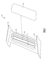
Figure 2 illustrates an exploded view of an example structural guide vane (SGV). -
Figure 3 illustrates a highly schematic view of damping media aligning along lines of a magnetic field. -
Figure 4 illustrates a shot peen media type of damping media aligning within a magnetic field. -
Figure 5 illustrates a section view of the SGV ofFigure 2 during assembly. -
Figure 6 illustrates a section view of the SGV ofFigure 2 when assembled. -
Figure 1 schematically illustrates agas turbine engine 20. Thegas turbine engine 20 is disclosed herein as a two-spool turbofan that generally incorporates afan section 22, acompressor section 24, a combustor section 26 and aturbine section 28. Alternative engines might include an augmentor section (not shown) among other systems or features. Thefan section 22 drives air along a bypass flow path B in a bypass duct defined within anacelle 15, while thecompressor section 24 drives air along a core flow path C for compression and communication into the combustor section 26 then expansion through theturbine section 28. Although depicted as a two-spool turbofan gas turbine engine in the disclosed non-limiting embodiment, it should be understood that the concepts described herein are not limited to use with two-spool turbofans as the teachings may be applied to other types of turbine engines including three-spool architectures. - The
exemplary engine 20 generally includes alow speed spool 30 and ahigh speed spool 32 mounted for rotation about an engine central longitudinal axis A relative to an enginestatic structure 36 viaseveral bearing systems 38. It should be understood thatvarious bearing systems 38 at various locations may alternatively or additionally be provided, and the location ofbearing systems 38 may be varied as appropriate to the application. - The
low speed spool 30 generally includes aninner shaft 40 that interconnects afan 42, a first (or low) pressure compressor 44 and a first (or low)pressure turbine 46. Theinner shaft 40 is connected to thefan 42 through a speed change mechanism, which in exemplarygas turbine engine 20 is illustrated as a gearedarchitecture 48 to drive thefan 42 at a lower speed than thelow speed spool 30. Thehigh speed spool 32 includes anouter shaft 50 that interconnects a second (or high)pressure compressor 52 and a second (or high)pressure turbine 54. Acombustor 56 is arranged in exemplarygas turbine engine 20 between thehigh pressure compressor 52 and thehigh pressure turbine 54. Amid-turbine frame 57 of the enginestatic structure 36 is arranged generally between thehigh pressure turbine 54 and thelow pressure turbine 46. Themid-turbine frame 57 further supports bearingsystems 38 in theturbine section 28. Theinner shaft 40 and theouter shaft 50 are concentric and rotate viabearing systems 38 about the engine central longitudinal axis A which is collinear with their longitudinal axes. - The core airflow is compressed by the low pressure compressor 44 then the
high pressure compressor 52, mixed and burned with fuel in thecombustor 56, then expanded over thehigh pressure turbine 54 andlow pressure turbine 46. Themid-turbine frame 57 includesairfoils 59 which are in the core airflow path C. Theturbines low speed spool 30 andhigh speed spool 32 in response to the expansion. It will be appreciated that each of the positions of thefan section 22,compressor section 24, combustor section 26,turbine section 28, and gearedarchitecture 48 may be varied. For example, gearedarchitecture 48 may be located aft of combustor section 26 or even aft ofturbine section 28, andfan section 22 may be positioned forward or aft of the location of gearedarchitecture 48. - The
engine 20 in one example is a high-bypass geared aircraft engine. In a further example, theengine 20 bypass ratio is greater than about six (6), with an example embodiment being greater than about ten (10), the gearedarchitecture 48 is an epicyclic gear train, such as a planetary gear system or other gear system, with a gear reduction ratio of greater than about 2.3 and thelow pressure turbine 46 has a pressure ratio that is greater than about five. In one disclosed embodiment, theengine 20 bypass ratio is greater than about ten (10:1), the fan diameter is significantly larger than that of the low pressure compressor 44, and thelow pressure turbine 46 has a pressure ratio that is greater than about five 5:1.Low pressure turbine 46 pressure ratio is pressure measured prior to inlet oflow pressure turbine 46 as related to the pressure at the outlet of thelow pressure turbine 46 prior to an exhaust nozzle. The gearedarchitecture 48 may be an epicycle gear train, such as a planetary gear system or other gear system, with a gear reduction ratio of greater than about 2.3:1. It should be understood, however, that the above parameters are only exemplary of one embodiment of a geared architecture engine and that the present invention is applicable to other gas turbine engines including direct drive turbofans. - A significant amount of thrust is provided by the bypass flow B due to the high bypass ratio. The
fan section 22 of theengine 20 is designed for a particular flight condition -- typically cruise at about 0.8 Mach and about 35,000 feet. The flight condition of 0.8 Mach and 35,000 ft (10,668 meters), with the engine at its best fuel consumption - also known as "bucket cruise Thrust Specific Fuel Consumption ('TSFC')" - is the industry standard parameter of 1bm of fuel being burned divided by lbf of thrust the engine produces at that minimum point. "Low fan pressure ratio" is the pressure ratio across the fan blade alone, without a Fan Exit Guide Vane ("FEGV") system. The low fan pressure ratio as disclosed herein according to one non-limiting embodiment is less than about 1.45. "Low corrected fan tip speed" is the actual fan tip speed in ft/sec divided by an industry standard temperature correction of [(Tram °R) / (518.7 °R)]0.5. The "Low corrected fan tip speed" as disclosed herein according to one non-limiting embodiment is less than about 1150 feet/second (350.5 meters/second). - Referring now to
Figure 2 with continuing reference toFigure 1 , at a position aft thefan 42, theengine 20 includes a structural guide vane (SGV) 62. Thestructural guide vanes 62 steers flow from thefan 42. TheSGV 62 also supports components of theengine 20 near thefan 42. TheSGV 62 is within an array of SGVs circumferentially distributed about the axis A. - The
SGV 62 includes avane body 64 extending from a radiallyinner platform 68 to a radiallyouter platform 72. In an installed position within theengine 20, the radiallyinner platform 68 mounts to an inner hub of theengine 20. The radiallyouter platform 72 mounts to an outer fan case of theengine 20. - The
vane body 64 includes a plurality ofcavities 76. In the example embodiment, thecavities 76 are approximately rectangular in shape. The number and location of thecavities 76 may vary depending on the application.Cavities 76 may be formed on one or both sides of theSGV 62 depending on the circumferential depth of theSGV 62 and the depth of thecavities 76. Thecavities 76 could also be formed in the radiallyinner platform 68 or radiallyouter platform 72. - The
cavities 76 are formed within a recessedarea 80 of thevane body 64. The recessedarea 80 receives a vane body cover 84 when theSGV 62 is assembled. Vibration damping of theSGV 62 is provided by damping media placed within thecavity 76. Thevane cover 84 is adhesively secured to the recessedarea 80 to hold the damping media within thecavities 76. Notably, in this example, the damping media is not held within any container. The damping media is in direct contact with thevane body 64 and thevane body cover 84. - Placing damping media within the
cavities 76, and then placing thecover 84 within the recessedarea 80 without disturbing the damping media, can be challenging. Example embodiments of this disclosure hold damping media within thecavities 76 during assembly using magnet fields to reduce these difficulties. - Referring to
Figure 3 , dampingmedia 88 that is magnetic orients alongmagnetic field lines 90 when positioned near amagnet 92. When oriented in this way, the dampingmedia 88 has the arcingstrands 94 following, generally, the paths of the magnetic field lines 90. - An
example damping media 88 for placement within thecavities 76 is shotpeen media 100 or bearing balls as shown inFigure 4 . Other example damping media includes sand, damping tape, ceramic particles, bearing balls, etc. - The example shot peen media is stainless steel in this example. The shot peen media is cold formed and are magnetic. Shot peen media are not intrinsically ferromagnetic, but, in this example, by virtue of being subject to high amounts of cold work, sufficient grain alignment is achieved to behave like a ferromagnetic material. The shot peen
media 100 is positioned within a magnetic field and are oriented in arcing strands. - Referring now to
Figures 5 and 6 ,magnets 104 are used to hold shotpeen media 100 within thecavities 76 before thevane cover 84 is secured. The tendency of theshot peen media 100 to align in arcing strands along magnetic field lines facilitates holding theshot peen media 100 within thecavities 76. - In this example, when the
shot peen media 100 are loaded into thecavities 76,magnets 104 are positioned along asurface 108 of the vane body opposite thecavities 76. Theexample magnets 104 are electromagnets that selectively inducemagnetic fields 110 in response to a command from a controller C. Themagnets 104 may be held within a fixture (not shown) that supports thevane body 64. - Generally, the
example magnets 104 are aligned such that themagnetic fields 110 that enter thecavities 76 through a side of thefloor 114 of thecavity 76 extend continuously to exit thecavity 76 through another side of thefloor 114. Also, themagnetic fields 110 that enter thecavity 76 through aside wall 118 of thecavity 76 extend continuously to exit thecavity 76 through the opposingside wall 122. - The magnetic force from the
magnets 104 pulls theshot peen media 100 into thecavities 76. The orientation of the flow fields 110 encourages theshot peen media 100 to orient themselves in strands within thecavities 76 along themagnetic fields 110. - Alignment along the flow fields 110 helps to ensure that the
shot peen media 100 do not extend out of thecavities 76 to interfere with abond line 126 between thecover 84 and thevane body 64. The alignment of themagnetic fields 110 encourages strands of theshot peen media 100 that start within thecavities 76 to also stop within thecavities 76 rather than interfering with thebond line 126. - To encourage the
magnetic fields 110 to align in this way, themagnets 104 have a first pole adjacent theside wall 118 and an opposing, second pole adjacent theside wall 122. - With no
shot peen media 100 interfering with thebond line 126, thecover 84 can then be adhesively secured within the recessedarea 80 to thevane body 64 to hold theshot peen media 100 within thecavities 76. Themagnets 104 are removed or demagnetized after thecover 84 is secured. The shot peenmedia 100 are then held within thecavities 76 by thecover 84. The shot peenmedia 100 directly contact thecover 84, thefloor 114, theside walls media 100 are free to move within thecavities 76 without interference from any separate container. - Vibration damping of the
SGV 62 can be influenced by the amount of shot peenmedia 100 within thecavities 76. Notably, the example method enables filling thecavities 76 with theshot peen media 100 without requiring a separate container within thecavities 76 holding theshot peen media 100. This maximizes damping area within a given area of thecavities 76. If containers were required, the container would occupy at least some of the space of thecavities 76. - In addition to the selection and placement of the damping material, which is the
shot peen media 100 in this example, various types of materials may be utilized to form thevane body 64 and thecover 84. In some examples, these components are formed of the same material, such as aluminum or organic matrix composite. In other examples, thevane body 64 and thecover 84 are formed of different materials to vary performance parameters of theSGV 62, such as weight, stiffness, or both. - The example damping is described with reference to the
SGV 62. Similar techniques of magnetic retention of damping media could be used in connection with other components, such as other airfoil components of the engine 20 (Figure 1 ) like vanes. - Although the different non-limiting embodiments are illustrated as having specific components, the embodiments of this disclosure are not limited to those particular combinations. It is possible to use some of the components or features from any of the non-limiting embodiments in combination with features or components from any of the other non-limiting embodiments.
- Although embodiments of this invention have been disclosed, a worker of ordinary skill in the art would recognize that certain modifications would come within the scope of this invention. For that reason, the following claims should be studied to determine the true scope and content of this invention.
Claims (15)
- A method of assembling a particle damped gas turbine engine component (62), comprising:holding damping media (100) within a cavity (76) of a gas turbine engine component (62) using magnetic force.
- The method of claim 1, including holding the damping media (100) within the cavity (76) of a structural guide vane (62).
- The method of claim 1 or 2, including covering the cavity (76) with a cover (84) during the holding.
- The method of claim 3, bonding the cover (84) to the cavity (76) and removing the magnetic force.
- The method of claim 4, wherein the damping media (100) is free to move within the cavity (76) after the bonding.
- The method of any preceding claim, including aligning magnetic fields to pass through the cavity (76) and hold damping media (100) within the cavity (76).
- The method of any preceding claim, wherein the damping media (100) comprises shot peen media.
- The method of any preceding claim, wherein an electromagnet selectively provides the magnetic force.
- The method of any preceding claim, including aligning a first pole adjacent a first side wall (118) of the cavity (76) and an opposing, second pole of the magnet adjacent an opposing, second side wall (122) of the cavity (76).
- A structural guide vane (62), comprising:a radially outer platform (72);a radially inner platform (68);a vane body (64) located between the radially outer platform (72) and the radially inner platform (68), wherein the vane body (64) includes one or more cavities (76);a vane cover (84); anda vibration damping material (100) filling the cavities (76) in direct contact with the vane body (64), the vane cover (84), or both.
- The structural guide vane of claim 10, wherein the vibration damping material (100) is shot peen media.
- The structural guide vane of claim 10 or 11, wherein the cavities (76) are formed on a side wall of the vane body (64).
- The structural guide vane of claim 10, 11 or 12, wherein the cavity is void of any container holding the vibration damping material.
- The structural guide vane of any of claims 10 to 13, wherein the vane cover (84) is adhesively bonded within a recessed area (80) of the vane body, wherein the cavities (76) are optionally formed within the recessed area (80), and/or wherein the vane cover (84) is bonded to the vane body (64) over the one or more cavities (76).
- The structural guide vane of any of claims 10 to 14, wherein the vane body (64) is aluminum.
Applications Claiming Priority (1)
| Application Number | Priority Date | Filing Date | Title |
|---|---|---|---|
| US201461939788P | 2014-02-14 | 2014-02-14 |
Publications (3)
| Publication Number | Publication Date |
|---|---|
| EP2907973A2 true EP2907973A2 (en) | 2015-08-19 |
| EP2907973A3 EP2907973A3 (en) | 2015-11-18 |
| EP2907973B1 EP2907973B1 (en) | 2017-12-13 |
Family
ID=52633056
Family Applications (1)
| Application Number | Title | Priority Date | Filing Date |
|---|---|---|---|
| EP15155055.5A Active EP2907973B1 (en) | 2014-02-14 | 2015-02-13 | Method of assembling a particle damped gas turbine engine component |
Country Status (2)
| Country | Link |
|---|---|
| US (1) | US9920650B2 (en) |
| EP (1) | EP2907973B1 (en) |
Cited By (3)
| Publication number | Priority date | Publication date | Assignee | Title |
|---|---|---|---|---|
| CN105136444A (en) * | 2015-09-24 | 2015-12-09 | 北京理工大学 | Particle chain shock absorber and particle chain damping measuring method |
| EP3051076A1 (en) * | 2015-01-29 | 2016-08-03 | United Technologies Corporation | Vibration damping assembly and method of damping vibration in a gas turbine engine |
| GB2551750A (en) * | 2016-06-29 | 2018-01-03 | Rolls Royce Plc | Cavity sealing |
Families Citing this family (5)
| Publication number | Priority date | Publication date | Assignee | Title |
|---|---|---|---|---|
| US10371165B2 (en) * | 2013-10-30 | 2019-08-06 | United Technologies Corporation | Fan blade composite ribs |
| US10808718B2 (en) | 2013-10-30 | 2020-10-20 | Raytheon Technologies Corporation | Fan blade composite segments |
| DE102016207874A1 (en) * | 2016-05-09 | 2017-11-09 | MTU Aero Engines AG | Impulse body module for a turbomachine |
| US11560801B1 (en) * | 2021-12-23 | 2023-01-24 | Rolls-Royce North American Technologies Inc. | Fan blade with internal magnetorheological fluid damping |
| US11746659B2 (en) | 2021-12-23 | 2023-09-05 | Rolls-Royce North American Technologies Inc. | Fan blade with internal shear-thickening fluid damping |
Family Cites Families (17)
| Publication number | Priority date | Publication date | Assignee | Title |
|---|---|---|---|---|
| US2862686A (en) | 1954-08-19 | 1958-12-02 | Thompson Prod Inc | Hollow vane with internal vibration dampener |
| US5056738A (en) | 1989-09-07 | 1991-10-15 | General Electric Company | Damper assembly for a strut in a jet propulsion engine |
| US5141400A (en) | 1991-01-25 | 1992-08-25 | General Electric Company | Wide chord fan blade |
| US5498137A (en) | 1995-02-17 | 1996-03-12 | United Technologies Corporation | Turbine engine rotor blade vibration damping device |
| US5725355A (en) | 1996-12-10 | 1998-03-10 | General Electric Company | Adhesive bonded fan blade |
| US5947688A (en) | 1997-12-22 | 1999-09-07 | General Electric Company | Frequency tuned hybrid blade |
| US6039542A (en) | 1997-12-24 | 2000-03-21 | General Electric Company | Panel damped hybrid blade |
| US6033186A (en) | 1999-04-16 | 2000-03-07 | General Electric Company | Frequency tuned hybrid blade |
| GB0100695D0 (en) | 2001-01-11 | 2001-02-21 | Rolls Royce Plc | a turbomachine blade |
| GB2400055B (en) | 2003-03-29 | 2006-01-11 | Rolls Royce Plc | A hollow component with internal damping |
| GB2403987B (en) * | 2003-07-11 | 2006-09-06 | Rolls Royce Plc | Blades |
| EP1566519A1 (en) | 2004-02-23 | 2005-08-24 | Siemens Aktiengesellschaft | High temperature resisting component for a fluidic machine and fluidic machine using this component. |
| US7980813B2 (en) | 2007-08-13 | 2011-07-19 | United Technologies Corporation | Fan outlet guide vane shroud insert repair |
| US8851844B2 (en) | 2007-10-31 | 2014-10-07 | Mitsubishi Heavy Industries, Ltd. | Stationary blade and steam turbine |
| US8177513B2 (en) | 2009-02-18 | 2012-05-15 | General Electric Company | Method and apparatus for a structural outlet guide vane |
| US20110211965A1 (en) | 2010-02-26 | 2011-09-01 | United Technologies Corporation | Hollow fan blade |
| US9957824B2 (en) * | 2013-03-15 | 2018-05-01 | United Technologies Corporation | Vibration damping for structural guide vanes |
-
2015
- 2015-02-12 US US14/620,292 patent/US9920650B2/en active Active
- 2015-02-13 EP EP15155055.5A patent/EP2907973B1/en active Active
Non-Patent Citations (1)
| Title |
|---|
| None |
Cited By (6)
| Publication number | Priority date | Publication date | Assignee | Title |
|---|---|---|---|---|
| EP3051076A1 (en) * | 2015-01-29 | 2016-08-03 | United Technologies Corporation | Vibration damping assembly and method of damping vibration in a gas turbine engine |
| US10260372B2 (en) | 2015-01-29 | 2019-04-16 | United Technologies Corporation | Vibration damping assembly and method of damping vibration in a gas turbine engine |
| CN105136444A (en) * | 2015-09-24 | 2015-12-09 | 北京理工大学 | Particle chain shock absorber and particle chain damping measuring method |
| GB2551750A (en) * | 2016-06-29 | 2018-01-03 | Rolls Royce Plc | Cavity sealing |
| GB2551750B (en) * | 2016-06-29 | 2020-03-25 | Rolls Royce Plc | Cavity sealing |
| US10612398B2 (en) | 2016-06-29 | 2020-04-07 | Rolls-Royce Plc | Cavity sealing |
Also Published As
| Publication number | Publication date |
|---|---|
| US9920650B2 (en) | 2018-03-20 |
| EP2907973A3 (en) | 2015-11-18 |
| EP2907973B1 (en) | 2017-12-13 |
| US20150233264A1 (en) | 2015-08-20 |
Similar Documents
| Publication | Publication Date | Title |
|---|---|---|
| EP2907973B1 (en) | Method of assembling a particle damped gas turbine engine component | |
| EP2971537B1 (en) | Vibration damping for structural guide vanes | |
| US10260372B2 (en) | Vibration damping assembly and method of damping vibration in a gas turbine engine | |
| EP3473807B1 (en) | Fan blade having a damping system, corresponding method of manufacturing and gas turbine engine | |
| EP3077625B1 (en) | Hollow blade having internal damper | |
| US10247003B2 (en) | Balanced rotating component for a gas powered engine | |
| EP3228831A1 (en) | Electromagnetic anti-windmilling system | |
| EP3318718B1 (en) | Fan for a gas turbine engine an corresponding method of securing fan blades to a rotor of a fan of a gas turbine engine | |
| EP2977552A1 (en) | Hollow fan blade for gas turbine engine including same | |
| US10179653B2 (en) | Pylon shape with geared turbofan for structural stiffness | |
| EP2904252B1 (en) | Static guide vane with internal hollow channels | |
| EP3591170B1 (en) | Potted stator vane with metal fillet | |
| WO2014149292A1 (en) | Titanium aluminide turbine exhaust structure | |
| EP3090128B1 (en) | Aluminum alloy airfoil with designed crystallographic texture |
Legal Events
| Date | Code | Title | Description |
|---|---|---|---|
| PUAI | Public reference made under article 153(3) epc to a published international application that has entered the european phase |
Free format text: ORIGINAL CODE: 0009012 |
|
| AK | Designated contracting states |
Kind code of ref document: A2 Designated state(s): AL AT BE BG CH CY CZ DE DK EE ES FI FR GB GR HR HU IE IS IT LI LT LU LV MC MK MT NL NO PL PT RO RS SE SI SK SM TR |
|
| AX | Request for extension of the european patent |
Extension state: BA ME |
|
| PUAL | Search report despatched |
Free format text: ORIGINAL CODE: 0009013 |
|
| AK | Designated contracting states |
Kind code of ref document: A3 Designated state(s): AL AT BE BG CH CY CZ DE DK EE ES FI FR GB GR HR HU IE IS IT LI LT LU LV MC MK MT NL NO PL PT RO RS SE SI SK SM TR |
|
| AX | Request for extension of the european patent |
Extension state: BA ME |
|
| RIC1 | Information provided on ipc code assigned before grant |
Ipc: B23P 15/04 20060101ALI20151009BHEP Ipc: F01D 5/16 20060101AFI20151009BHEP Ipc: F16F 7/01 20060101ALI20151009BHEP Ipc: B23Q 3/15 20060101ALI20151009BHEP Ipc: B25B 11/00 20060101ALI20151009BHEP |
|
| 17P | Request for examination filed |
Effective date: 20160518 |
|
| RBV | Designated contracting states (corrected) |
Designated state(s): AL AT BE BG CH CY CZ DE DK EE ES FI FR GB GR HR HU IE IS IT LI LT LU LV MC MK MT NL NO PL PT RO RS SE SI SK SM TR |
|
| RAP1 | Party data changed (applicant data changed or rights of an application transferred) |
Owner name: UNITED TECHNOLOGIES CORPORATION |
|
| GRAP | Despatch of communication of intention to grant a patent |
Free format text: ORIGINAL CODE: EPIDOSNIGR1 |
|
| STAA | Information on the status of an ep patent application or granted ep patent |
Free format text: STATUS: GRANT OF PATENT IS INTENDED |
|
| INTG | Intention to grant announced |
Effective date: 20170621 |
|
| GRAS | Grant fee paid |
Free format text: ORIGINAL CODE: EPIDOSNIGR3 |
|
| GRAA | (expected) grant |
Free format text: ORIGINAL CODE: 0009210 |
|
| STAA | Information on the status of an ep patent application or granted ep patent |
Free format text: STATUS: THE PATENT HAS BEEN GRANTED |
|
| REG | Reference to a national code |
Ref country code: GB Ref legal event code: FG4D |
|
| REG | Reference to a national code |
Ref country code: AT Ref legal event code: REF Ref document number: 954584 Country of ref document: AT Kind code of ref document: T Effective date: 20171215 Ref country code: CH Ref legal event code: EP |
|
| REG | Reference to a national code |
Ref country code: IE Ref legal event code: FG4D |
|
| REG | Reference to a national code |
Ref country code: DE Ref legal event code: R096 Ref document number: 602015006554 Country of ref document: DE |
|
| REG | Reference to a national code |
Ref country code: FR Ref legal event code: PLFP Year of fee payment: 4 |
|
| REG | Reference to a national code |
Ref country code: NL Ref legal event code: MP Effective date: 20171213 |
|
| PG25 | Lapsed in a contracting state [announced via postgrant information from national office to epo] |
Ref country code: FI Free format text: LAPSE BECAUSE OF FAILURE TO SUBMIT A TRANSLATION OF THE DESCRIPTION OR TO PAY THE FEE WITHIN THE PRESCRIBED TIME-LIMIT Effective date: 20171213 Ref country code: SE Free format text: LAPSE BECAUSE OF FAILURE TO SUBMIT A TRANSLATION OF THE DESCRIPTION OR TO PAY THE FEE WITHIN THE PRESCRIBED TIME-LIMIT Effective date: 20171213 Ref country code: NO Free format text: LAPSE BECAUSE OF FAILURE TO SUBMIT A TRANSLATION OF THE DESCRIPTION OR TO PAY THE FEE WITHIN THE PRESCRIBED TIME-LIMIT Effective date: 20180313 |
|
| REG | Reference to a national code |
Ref country code: AT Ref legal event code: MK05 Ref document number: 954584 Country of ref document: AT Kind code of ref document: T Effective date: 20171213 |
|
| PG25 | Lapsed in a contracting state [announced via postgrant information from national office to epo] |
Ref country code: HR Free format text: LAPSE BECAUSE OF FAILURE TO SUBMIT A TRANSLATION OF THE DESCRIPTION OR TO PAY THE FEE WITHIN THE PRESCRIBED TIME-LIMIT Effective date: 20171213 Ref country code: LV Free format text: LAPSE BECAUSE OF FAILURE TO SUBMIT A TRANSLATION OF THE DESCRIPTION OR TO PAY THE FEE WITHIN THE PRESCRIBED TIME-LIMIT Effective date: 20171213 Ref country code: GR Free format text: LAPSE BECAUSE OF FAILURE TO SUBMIT A TRANSLATION OF THE DESCRIPTION OR TO PAY THE FEE WITHIN THE PRESCRIBED TIME-LIMIT Effective date: 20180314 Ref country code: BG Free format text: LAPSE BECAUSE OF FAILURE TO SUBMIT A TRANSLATION OF THE DESCRIPTION OR TO PAY THE FEE WITHIN THE PRESCRIBED TIME-LIMIT Effective date: 20180313 Ref country code: RS Free format text: LAPSE BECAUSE OF FAILURE TO SUBMIT A TRANSLATION OF THE DESCRIPTION OR TO PAY THE FEE WITHIN THE PRESCRIBED TIME-LIMIT Effective date: 20171213 |
|
| PG25 | Lapsed in a contracting state [announced via postgrant information from national office to epo] |
Ref country code: NL Free format text: LAPSE BECAUSE OF FAILURE TO SUBMIT A TRANSLATION OF THE DESCRIPTION OR TO PAY THE FEE WITHIN THE PRESCRIBED TIME-LIMIT Effective date: 20171213 |
|
| PG25 | Lapsed in a contracting state [announced via postgrant information from national office to epo] |
Ref country code: CY Free format text: LAPSE BECAUSE OF FAILURE TO SUBMIT A TRANSLATION OF THE DESCRIPTION OR TO PAY THE FEE WITHIN THE PRESCRIBED TIME-LIMIT Effective date: 20171213 Ref country code: EE Free format text: LAPSE BECAUSE OF FAILURE TO SUBMIT A TRANSLATION OF THE DESCRIPTION OR TO PAY THE FEE WITHIN THE PRESCRIBED TIME-LIMIT Effective date: 20171213 Ref country code: SK Free format text: LAPSE BECAUSE OF FAILURE TO SUBMIT A TRANSLATION OF THE DESCRIPTION OR TO PAY THE FEE WITHIN THE PRESCRIBED TIME-LIMIT Effective date: 20171213 Ref country code: CZ Free format text: LAPSE BECAUSE OF FAILURE TO SUBMIT A TRANSLATION OF THE DESCRIPTION OR TO PAY THE FEE WITHIN THE PRESCRIBED TIME-LIMIT Effective date: 20171213 Ref country code: ES Free format text: LAPSE BECAUSE OF FAILURE TO SUBMIT A TRANSLATION OF THE DESCRIPTION OR TO PAY THE FEE WITHIN THE PRESCRIBED TIME-LIMIT Effective date: 20171213 |
|
| PG25 | Lapsed in a contracting state [announced via postgrant information from national office to epo] |
Ref country code: PL Free format text: LAPSE BECAUSE OF FAILURE TO SUBMIT A TRANSLATION OF THE DESCRIPTION OR TO PAY THE FEE WITHIN THE PRESCRIBED TIME-LIMIT Effective date: 20171213 Ref country code: SM Free format text: LAPSE BECAUSE OF FAILURE TO SUBMIT A TRANSLATION OF THE DESCRIPTION OR TO PAY THE FEE WITHIN THE PRESCRIBED TIME-LIMIT Effective date: 20171213 Ref country code: IT Free format text: LAPSE BECAUSE OF FAILURE TO SUBMIT A TRANSLATION OF THE DESCRIPTION OR TO PAY THE FEE WITHIN THE PRESCRIBED TIME-LIMIT Effective date: 20171213 Ref country code: AT Free format text: LAPSE BECAUSE OF FAILURE TO SUBMIT A TRANSLATION OF THE DESCRIPTION OR TO PAY THE FEE WITHIN THE PRESCRIBED TIME-LIMIT Effective date: 20171213 Ref country code: IS Free format text: LAPSE BECAUSE OF FAILURE TO SUBMIT A TRANSLATION OF THE DESCRIPTION OR TO PAY THE FEE WITHIN THE PRESCRIBED TIME-LIMIT Effective date: 20180413 Ref country code: RO Free format text: LAPSE BECAUSE OF FAILURE TO SUBMIT A TRANSLATION OF THE DESCRIPTION OR TO PAY THE FEE WITHIN THE PRESCRIBED TIME-LIMIT Effective date: 20171213 |
|
| REG | Reference to a national code |
Ref country code: CH Ref legal event code: PL Ref country code: DE Ref legal event code: R097 Ref document number: 602015006554 Country of ref document: DE |
|
| PG25 | Lapsed in a contracting state [announced via postgrant information from national office to epo] |
Ref country code: MC Free format text: LAPSE BECAUSE OF FAILURE TO SUBMIT A TRANSLATION OF THE DESCRIPTION OR TO PAY THE FEE WITHIN THE PRESCRIBED TIME-LIMIT Effective date: 20171213 |
|
| PLBE | No opposition filed within time limit |
Free format text: ORIGINAL CODE: 0009261 |
|
| STAA | Information on the status of an ep patent application or granted ep patent |
Free format text: STATUS: NO OPPOSITION FILED WITHIN TIME LIMIT |
|
| 26N | No opposition filed |
Effective date: 20180914 |
|
| REG | Reference to a national code |
Ref country code: IE Ref legal event code: MM4A |
|
| REG | Reference to a national code |
Ref country code: BE Ref legal event code: MM Effective date: 20180228 |
|
| PG25 | Lapsed in a contracting state [announced via postgrant information from national office to epo] |
Ref country code: LU Free format text: LAPSE BECAUSE OF NON-PAYMENT OF DUE FEES Effective date: 20180213 Ref country code: CH Free format text: LAPSE BECAUSE OF NON-PAYMENT OF DUE FEES Effective date: 20180228 Ref country code: LI Free format text: LAPSE BECAUSE OF NON-PAYMENT OF DUE FEES Effective date: 20180228 Ref country code: DK Free format text: LAPSE BECAUSE OF FAILURE TO SUBMIT A TRANSLATION OF THE DESCRIPTION OR TO PAY THE FEE WITHIN THE PRESCRIBED TIME-LIMIT Effective date: 20171213 |
|
| PG25 | Lapsed in a contracting state [announced via postgrant information from national office to epo] |
Ref country code: IE Free format text: LAPSE BECAUSE OF NON-PAYMENT OF DUE FEES Effective date: 20180213 |
|
| PG25 | Lapsed in a contracting state [announced via postgrant information from national office to epo] |
Ref country code: SI Free format text: LAPSE BECAUSE OF FAILURE TO SUBMIT A TRANSLATION OF THE DESCRIPTION OR TO PAY THE FEE WITHIN THE PRESCRIBED TIME-LIMIT Effective date: 20171213 Ref country code: BE Free format text: LAPSE BECAUSE OF NON-PAYMENT OF DUE FEES Effective date: 20180228 |
|
| PG25 | Lapsed in a contracting state [announced via postgrant information from national office to epo] |
Ref country code: MT Free format text: LAPSE BECAUSE OF NON-PAYMENT OF DUE FEES Effective date: 20180213 |
|
| PG25 | Lapsed in a contracting state [announced via postgrant information from national office to epo] |
Ref country code: TR Free format text: LAPSE BECAUSE OF FAILURE TO SUBMIT A TRANSLATION OF THE DESCRIPTION OR TO PAY THE FEE WITHIN THE PRESCRIBED TIME-LIMIT Effective date: 20171213 |
|
| PG25 | Lapsed in a contracting state [announced via postgrant information from national office to epo] |
Ref country code: PT Free format text: LAPSE BECAUSE OF FAILURE TO SUBMIT A TRANSLATION OF THE DESCRIPTION OR TO PAY THE FEE WITHIN THE PRESCRIBED TIME-LIMIT Effective date: 20171213 |
|
| PG25 | Lapsed in a contracting state [announced via postgrant information from national office to epo] |
Ref country code: LT Free format text: LAPSE BECAUSE OF FAILURE TO SUBMIT A TRANSLATION OF THE DESCRIPTION OR TO PAY THE FEE WITHIN THE PRESCRIBED TIME-LIMIT Effective date: 20171213 Ref country code: HU Free format text: LAPSE BECAUSE OF FAILURE TO SUBMIT A TRANSLATION OF THE DESCRIPTION OR TO PAY THE FEE WITHIN THE PRESCRIBED TIME-LIMIT; INVALID AB INITIO Effective date: 20150213 Ref country code: MK Free format text: LAPSE BECAUSE OF NON-PAYMENT OF DUE FEES Effective date: 20171213 |
|
| PG25 | Lapsed in a contracting state [announced via postgrant information from national office to epo] |
Ref country code: AL Free format text: LAPSE BECAUSE OF FAILURE TO SUBMIT A TRANSLATION OF THE DESCRIPTION OR TO PAY THE FEE WITHIN THE PRESCRIBED TIME-LIMIT Effective date: 20171213 |
|
| REG | Reference to a national code |
Ref country code: DE Ref legal event code: R081 Ref document number: 602015006554 Country of ref document: DE Owner name: RAYTHEON TECHNOLOGIES CORPORATION (N.D.GES.D.S, US Free format text: FORMER OWNER: UNITED TECHNOLOGIES CORPORATION, FARMINGTON, CONN., US Ref country code: DE Ref legal event code: R081 Ref document number: 602015006554 Country of ref document: DE Owner name: RTX CORPORATION (N.D.GES.D. STAATES DELAWARE),, US Free format text: FORMER OWNER: UNITED TECHNOLOGIES CORPORATION, FARMINGTON, CONN., US |
|
| P01 | Opt-out of the competence of the unified patent court (upc) registered |
Effective date: 20230520 |
|
| REG | Reference to a national code |
Ref country code: DE Ref legal event code: R081 Ref document number: 602015006554 Country of ref document: DE Owner name: RTX CORPORATION (N.D.GES.D. STAATES DELAWARE),, US Free format text: FORMER OWNER: RAYTHEON TECHNOLOGIES CORPORATION (N.D.GES.D.STAATES DELAWARE), ARLINGTON, VA, US |
|
| PGFP | Annual fee paid to national office [announced via postgrant information from national office to epo] |
Ref country code: GB Payment date: 20260121 Year of fee payment: 12 |
|
| PGFP | Annual fee paid to national office [announced via postgrant information from national office to epo] |
Ref country code: DE Payment date: 20260121 Year of fee payment: 12 |
|
| PGFP | Annual fee paid to national office [announced via postgrant information from national office to epo] |
Ref country code: FR Payment date: 20260121 Year of fee payment: 12 |