EP2907964A1 - Cone Cutter for Rotary Cutting Bit - Google Patents
Cone Cutter for Rotary Cutting Bit Download PDFInfo
- Publication number
- EP2907964A1 EP2907964A1 EP14154781.0A EP14154781A EP2907964A1 EP 2907964 A1 EP2907964 A1 EP 2907964A1 EP 14154781 A EP14154781 A EP 14154781A EP 2907964 A1 EP2907964 A1 EP 2907964A1
- Authority
- EP
- European Patent Office
- Prior art keywords
- cutter
- passageways
- facing surface
- buttons
- cone
- Prior art date
- Legal status (The legal status is an assumption and is not a legal conclusion. Google has not performed a legal analysis and makes no representation as to the accuracy of the status listed.)
- Withdrawn
Links
- 238000005520 cutting process Methods 0.000 claims abstract description 49
- 239000012530 fluid Substances 0.000 claims abstract description 22
- 239000011435 rock Substances 0.000 claims description 7
- 230000000712 assembly Effects 0.000 claims description 5
- 238000000429 assembly Methods 0.000 claims description 5
- 239000000428 dust Substances 0.000 description 13
- 239000002245 particle Substances 0.000 description 9
- 239000002826 coolant Substances 0.000 description 4
- 238000001816 cooling Methods 0.000 description 4
- 238000005553 drilling Methods 0.000 description 4
- 238000009825 accumulation Methods 0.000 description 3
- 239000000463 material Substances 0.000 description 3
- 230000007423 decrease Effects 0.000 description 2
- 230000002028 premature Effects 0.000 description 2
- 238000013019 agitation Methods 0.000 description 1
- 230000001010 compromised effect Effects 0.000 description 1
- 238000011109 contamination Methods 0.000 description 1
- 239000012809 cooling fluid Substances 0.000 description 1
- 230000001627 detrimental effect Effects 0.000 description 1
- 230000000694 effects Effects 0.000 description 1
- 239000012634 fragment Substances 0.000 description 1
- 238000004519 manufacturing process Methods 0.000 description 1
- 238000005192 partition Methods 0.000 description 1
- 230000037361 pathway Effects 0.000 description 1
- 230000000149 penetrating effect Effects 0.000 description 1
- 230000035515 penetration Effects 0.000 description 1
- 238000005096 rolling process Methods 0.000 description 1
- 238000003466 welding Methods 0.000 description 1
Images




Classifications
-
- E—FIXED CONSTRUCTIONS
- E21—EARTH OR ROCK DRILLING; MINING
- E21B—EARTH OR ROCK DRILLING; OBTAINING OIL, GAS, WATER, SOLUBLE OR MELTABLE MATERIALS OR A SLURRY OF MINERALS FROM WELLS
- E21B10/00—Drill bits
- E21B10/08—Roller bits
- E21B10/22—Roller bits characterised by bearing, lubrication or sealing details
- E21B10/24—Roller bits characterised by bearing, lubrication or sealing details characterised by lubricating details
-
- E—FIXED CONSTRUCTIONS
- E21—EARTH OR ROCK DRILLING; MINING
- E21B—EARTH OR ROCK DRILLING; OBTAINING OIL, GAS, WATER, SOLUBLE OR MELTABLE MATERIALS OR A SLURRY OF MINERALS FROM WELLS
- E21B10/00—Drill bits
- E21B10/08—Roller bits
- E21B10/22—Roller bits characterised by bearing, lubrication or sealing details
- E21B10/23—Roller bits characterised by bearing, lubrication or sealing details with drilling fluid supply to the bearings
Definitions
- the present invention relates to a cone cutter for mounting at a rotary cutting bit and in particular, although not exclusively, to a cone cutter having a main body and a plurality of vent passageways extending through the wall of the body to be capable of directing a flow of a fluid outwardly from an internal cavity of the cutter.
- Rotary drills have emerged as an effective tool for specific drilling operations such as the creation of blast holes and geothermal wells.
- the drill typically comprises a rotary drill bit having three journal arms that mount respective cone-shaped rolling cutters via bearing assemblies that includes rollers and balls to minimise friction during use.
- the drill bit is attached to one end of a drill string that is driven into the borehole via a rig.
- the cutting action is achieved by generating axial feed and rotational drive forces that are transmitted to the drill bit via the drill rods couple end-to-end.
- Each of the cone-shaped cutters comprise hardened cutting elements typically referred to as buttons, inserts, chisels and the like being commonly formed from a cemented carbide material.
- the cutting buttons are positioned at discreet external annular rows on the cone cutter with different buttons at different axial regions being optimised to achieve the desired cutting action as the drill string and drill bit rotate.
- a cone cutter for mounting at a rotary cutting bit, the cone cutter comprising: a generally cone-shaped main body having an annular wall extending around a longitudinal axis of the cutter, the wall defined by a radially outward facing surface and a radially inward facing surface, an internal cavity defined by the inward facing surface suitable for mounting on a bearing assembly of a rotary cutting bit; a plurality of cutting buttons mounted at the outward facing surface; characterised by: a plurality of vent passageways extending through the wall between the outward and inward facing surfaces to allow a flow of a fluid from within the cavity to exit the main body through the wall.
- the cone cutter may be further defined as comprising an apex region and a base region wherein the walls extend axially between the apex region and the base region.
- the cavity is open at the base region by way of a generally circular mouth.
- the passageways extend transverse and optionally perpendicular to the axis within the wall at an axial position between the apex region and the base region.
- the shape, configuration and size of the mouth is configured for positioning over and about an axel or spindle that supports the bearing assembly at the journal arm such that the mouth comprises a diameter being slightly greater than a diameter of the spindle.
- the cone cutter and in particular the outward facing surface may be considered to be divided into axial sections extending between the apex region and base region.
- the relative angular alignment of the outward facing surface at the different axel regions is different so as to create the cone-shaped profile.
- the cutter comprises a plurality of sections arranged axially at the outward facing surface, the sections comprising: a heel row provided towards a base of the cone having heel buttons; a drive row provided towards an apex of the cone having drive buttons; and a gauge row provided axially intermediate the heel and drive rows, the gauge row comprising gauge buttons.
- the heel row represents an 'under-cut' region of the cutter such that the outward facing surface is inclined at an opposite angle to the outward facing surface towards the dome region relative to the axis.
- the passageways emerge at the outward facing surface within the heel row.
- Directing the exhaust fluid flow through the axially rearward facing heel row of the cutter is advantageous to provide an exhaust fluid stream that projects axially rearward and radially outward from the cutter. This has the effect of transporting rearwardly and axially dust and debris particles away from the journal arm and in particular the region between the cutter and the journal.
- Such an arrangement is advantageous over conventional bit assemblies that exhaust the fluid through the cavity mouth as such arrangements can lead to dust particles being forced into the cavity.
- the axially rearward and radially outward flow path from the current passageways is effective to continuously clean the region of the journal arm immediately behind the cutter.
- air turbulence at an axially forward position of the cutter is minimise as the majority of the air stream is specifically directed axially rearward from the cutting buttons and is not deflected or reflected by the journal arm as with conventional cutting bit arrangements.
- the passageways continue through and emerge at respective heel buttons.
- the cutter comprises a plurality of specifically configured cutting buttons that have a central bore having a diameter corresponding to a diameter of each passageway so as to mate in co-alignment as a seamless continuous passageway extending through the wall and the respective cutting button.
- Exiting the passageways at cutting buttons is advantageous to protect the exit aperture of each passageway from damage caused by frictional contact with the rock and debris material within the borehole.
- the passageways may exit the wall at the region of the outward facing surface between cutting buttons. In such arrangements, the exit aperture of the passageways may be protected by suitable annular shields or guards that surround the immediate vicinity of the edge that defines the exit aperture at the outward facing surface.
- the passageways comprise an elongate length extending between the outward and inward facing surfaces that is aligned at a declined angle through the wall relative to the axis such that the passageways emerge at the inward facing surface at an axial position closer to the apex of the cone than a region where the passageways emerge at the outward facing surface.
- Such an arrangement is advantageous to avoid debris particles and dust traveling radially inward through the passageways from the dust laden environment surrounding the cone cutter.
- the transverse orientation of the passageways relative to the axis is effective to create a desired flow path of the coolant fluid within the cavity and around the bearings.
- the under-cut region of the heel row is advantageous for the exhaust apertures of the passageways as this region is effectively shielded from the dust particles by the majority of the cone main body.
- an orientation of the passageways is substantially perpendicular to the outward facing surface at the heel row.
- the transverse alignment of the passageways is advantageous to provide a smooth air flow path from within the cavity and to assist with cooling of the bearing assembly by creating a desired air flow circuit within the cavity.
- the passageways emerge at the inward facing surface at substantially the same axial position corresponding to the position of the gauge row. This relative axial position of the entry apertures of the respective passageways does not compromise the structural integrity of the cutter and is effective to optimise the air flow path and cooling of the bearing assembly.
- the outward facing surface at the heel row is inclined relative to the axis at an angle in the range 50 to 70° or 55 to 65°
- This relative inclined orientation of the heel row surface enables the heel buttons to assist the cutting action of the gauge buttons and to exhaust the coolant fluid in a desired orientation as relatively focussed streams of fluid as the cone cutter rotates.
- the cone cutter may comprise a first set of passageways emerging at the heel row and a second set of passageways emerging at the gauge row.
- the cutter may comprise a further set of passageways emerging at the drive row.
- any such further passageway may emerge at the outward facing surface within respective cutting buttons so as to protect the exit aperture of the passageways from frictional wear.
- the passageways comprise a length having a substantially uniform cross-sectional area between the inward and outward facing surfaces.
- a generally unchanging cross sectional area of the passageway is effective to provide a smooth and unrestricted exhaust of coolant fluid from within the cavity.
- the cross sectional area of each passageway decreases from the inward to the outward facing surface to reduce the likelihood of debris rock particles penetrating into the cavity and in contact with the bearings via the passageways.
- a diameter of the passageways is substantially half a diameter of a base of each of the cutting buttons. Accordingly, the integrity of the cutting buttons that comprise a central bore is not unduly compromised. Such specifically configured buttons are therefore still capable of assisting with the cutting action of adjacent 'unmodified' buttons.
- the passageways are uniformly distributed around the axis.
- the even-spacing of the passageways around the axis in a circumferential direction provides a balanced fluid flow that does not compromise the rotational stability of the cutter mounted at the bearing assembly.
- the entry and exit apertures of each of the set of passageway are positioned at the same axial location/height at the wall of the cutter. Again, such an arrangement provides a smooth exit fluid flow from the cutter and a controlled flow of fluid around the bearing assembly.
- a rotary cutting bit for cutting rock comprising: at least one journal arm; a bearing assembly mounted at the journal arm; a cutter as claimed herein mounted at the bearing assembly via the cavity so as to be capable of rotation relative to the journal arm.
- the cutting bit may comprise three arms and three respective bearing assemblies and cutters. Such an arrangement is advantageous to optimise the cutting or drill rate with respect to the rotational force imparted to the drill string from the drill rig.
- a cutting head 100 is formed as a cutting bit intended for rotatory crushing drilling of rock.
- the cutting bit 100 comprises a cutting end 101 and an axially rearward attachment end 102 configured for attachment to one end of a drill string (not shown) forming part of a drill assembly operated via a drilling machine or rig (not shown) configured to provide axial and rotational drive to the cutting bit 100 via the drill string.
- Cutting bit 100 comprises three journal arms 105 projecting axially forward from attachment end 102 and being aligned slightly radially outward such that cutting end 101 comprises a generally larger diameter than attachment end 102.
- a generally conical shaped cone cutter 103 is mounted at one end of each journal arm 105 so as to be capable of rotation relative to arm 105 and independent rotation about a separate axis relative to the general rotation of cutting bit 100 and the drill string (not shown).
- a bearing assembly indicated generally by reference 200 is provided at an end 207 of each journal arm 105.
- Bearing assembly 200 may be mounted at journal arm end 207 via a suitable spindle or axel (not shown) and comprises a first raceways 201 located at a base region of bearing assembly 200 and a second raceway 203 positioned at a tip region of assembly 200.
- a third raceway 202 is positioned between the first and second raceways 201, 203.
- a first set of roller bearings 204 is mounted at first raceway 201 and a second set of roller bearings 206 is mounted at second raceway 203.
- a plurality of ball bearings 205 are mounted at third raceway 202 so as to provide a minimum-friction bearing assembly 200 upon which is mounted cone cutter 103.
- each cone cutter 103 comprises a generally cone or dome shaped configuration having a hollow structure.
- the annular cone cutter 103 comprises an internal cavity 300 defined by a radially internal facing surface 301.
- An opposed radially outward facing surface is indicated generally by reference 302 and represents a cutting face region of cutter 103.
- cone cutter 103 may be divided into axial sections at the outer facing surface 302 and comprises a heel row 106, a gauge row 107, a drive row 108 and an inner or apex region 109.
- a plurality of sets of cutting buttons are provided at each respective axial section including in particular heel row buttons 110, gauge buttons 111 (and 112), drive buttons 113 and inner buttons 114.
- Each of the cutting buttons 104 comprises a working tip having a generally pointed configuration.
- each cutting button 104 or specific set of buttons 104 may be semi-spherical, conical, ballistic, semi-ballistic or chisel shaped.
- Each button 104 is formed from a wear resistant cemented carbide based material. Referring to figures 3 and 4 a wall 401 of the cone cutter 103 is defined generally between the inward facing surface 301 and the outward facing surface 302.
- a plurality of generally cylindrical recesses are formed within wall 401 at each axial section to extend radially inward from outward facing surface 301.
- Each recess 307 accommodates a corresponding cutting button 104 via conventional welding and/or press/shrink fitting.
- Cone cutter 103 is mounted at bearing assembly 200 via the positioning of assembly 200 within cavity 300 such that the inward facing surface 301 is orientated around bearings 204, 205, 206.
- the air is configured to penetrate and circulate between the region of bearing assembly 200 and the inward facing surface 301.
- a base region of cavity 300 is defined by an annular edge 306 formed as a mouth in the underside of cone cutter 103.
- Mouth 306 is configured for positioning in close proximity to an annular shoulder 208 provided at a base region of assembly 200 and formed at journal arm end 207.
- Each cone cutter 103 comprises a plurality of vents that extend through the cone wall 401 to exhaust the cooling air circulating around bearing assembly 200.
- a plurality of passageways 304 extend through wall 401 between inward facing surface 301 and outward facing surface 302.
- Each passageway 304 is aligned transverse to a central longitudinal axis 400 extending through cone cutter 103 with each passageway comprising an entry aperture 303 provided at inward facing surface 301 and an exit aperture 305 provided at a trough region 406 of selected recesses 307.
- passageways 304 are positioned to extend through cutter wall 401 in the axial vicinity of mouth 306. That is, each passageway entrance 303 is aligned axially approximately at the gauge row 107 whilst the passageway exit aperture 305 is positioned approximately at heel row 106.
- six passageways 304 are provided through wall 401 and accordingly six respective heel row buttons 110 are modified so as to comprise a corresponding internal bore (or passageway) 402 extending between a base end 404 and an exit or cutting end 403.
- Passageways 304 and 402 are aligned coaxially so as to provide a single passageway extending from entry aperture 303 at internal cavity 300 and exiting at an aperture 405 provided at the button exit end 403.
- a cross sectional area of passageway 304, 402 is approximately half of a cross sectional area of button 110 at base end 404.
- the air flow vent passageways 304, 402 are aligned transverse to axis 400 so as to be declined downwardly from axis 400.
- entry aperture 303 is positioned axially closer to apex region 109 relative to exit aperture 405 that is positioned at an axially similar position to mouth 306.
- a cross sectional area of passageways 304, 402 is tapered so as to decrease from entry aperture 303 at inward facing surface 301 to exit aperture 405 at the outer cutting exit end 403 of heel row button 110.
- the cross sectional area of passageways 304, 402 may be substantially uniform between apertures 303 and 405.
- cutter external surface 302 at heel row region 106 is inclined relative to axis 400 and is orientated at transverse angle b.
- b is substantially 50 to 55°.
- Passageways 304, 402 are aligned perpendicular to the orientation of outward facing surface 302 at heel row 106 and are aligned at a declined angle a relative to axis 400.
- angle a is substantially in the range 140 to 150° relative to axis 400.
- entry aperture 303 comprises a generally oval shape profile at inward facing surface 301. Each entry aperture 303 is aligned at the same axial position corresponding generally to the same axial position as gauge buttons 111.
- Positioning passageways 304, 402 to exit at the region of heel row section 106 is advantageous for a number of reasons.
- the exit airflow stream from each button exit aperture 405 is directed axially rearward and radially outward relative to axis 400. Accordingly, any dust or debris is prevented from accumulation at the region of journal arm shoulder 208 and in particular the interface region between cone cutter mouth 306 and journal arm 105.
- Such an arrangement prevents ingress of dust or particulates into cavity 300 and also eliminates accelerated frictional wear of arm 105 and cutter 103 due to the accumulation of debris at the junction between these two components 103, 105.
- additional or alternative fluid flow exit passageways 304, 402 may be provided at different axial positions through cone cutter wall 401.
- the fluid flow exit passageways 304, 402 may extend in the gauge row 107, the drive row 108 and/or the inner row 109.
- specifically modified buttons 104 would accordingly be provided in the same manner as described referring to figures 1 to 6 and with reference to the heel row buttons 110.
Landscapes
- Engineering & Computer Science (AREA)
- Life Sciences & Earth Sciences (AREA)
- Geology (AREA)
- Mining & Mineral Resources (AREA)
- Mechanical Engineering (AREA)
- Physics & Mathematics (AREA)
- Environmental & Geological Engineering (AREA)
- Fluid Mechanics (AREA)
- General Life Sciences & Earth Sciences (AREA)
- Geochemistry & Mineralogy (AREA)
- Earth Drilling (AREA)
Abstract
A cone cutter (103) for mounting at a rotary cutting bit (100) having a plurality of vent passageways (304) extending through the wall (401) between an inward (301) and an outward (302) facing surface of the cutter. The passageways allow an exhaust flow of fluid from within the cavity and are optimised to direct the exhaust fluid flow stream radially outward and axially rearward of the cone cutter.
Description
- The present invention relates to a cone cutter for mounting at a rotary cutting bit and in particular, although not exclusively, to a cone cutter having a main body and a plurality of vent passageways extending through the wall of the body to be capable of directing a flow of a fluid outwardly from an internal cavity of the cutter.
- Rotary drills have emerged as an effective tool for specific drilling operations such as the creation of blast holes and geothermal wells. The drill typically comprises a rotary drill bit having three journal arms that mount respective cone-shaped rolling cutters via bearing assemblies that includes rollers and balls to minimise friction during use.
- Typically, the drill bit is attached to one end of a drill string that is driven into the borehole via a rig. The cutting action is achieved by generating axial feed and rotational drive forces that are transmitted to the drill bit via the drill rods couple end-to-end. Each of the cone-shaped cutters comprise hardened cutting elements typically referred to as buttons, inserts, chisels and the like being commonly formed from a cemented carbide material. The cutting buttons are positioned at discreet external annular rows on the cone cutter with different buttons at different axial regions being optimised to achieve the desired cutting action as the drill string and drill bit rotate.
- So as to cool the antifriction bearings, air is typically supplied down the drill string through the journal arms and into the bearing assemblies. The air circulates around the bearings within each cavity of each cone cutter and is vented via the cavity mouth. Example rotating bits and cutters are described in
US 3,193,028 ;US 3,921,735 ;US 4,688,651 andUS 4,421,184 . - However, existing cone cutters and rotary drill bits are disadvantageous for a number of reasons. Principally, the air is vented through the mouth region of the cone cutter cavity and this introduces problems and complexity with attempting to seal or partition the cavity and hence the bearing assembly from the dust laden environment within which the cutting bit is operational. It is not uncommon for dust and particles to pass into the cavity and cause premature wear of the bearings. Additionally, exhausting through the cavity mouth and around the spindle that mounts the bearing assembly at the journal arm causes undesirable agitation of the dust particulates around the region of the cone cutter that can lead to accumulation of dust and debris at undesirable locations that may be detrimental to the drilling rate and cause premature wear of the drill bit components. Accordingly, what is required is a cone cutter and a drill bit that addresses the above problem.
- It is an objective of the present invention to provide a cone cutter for a drill bit having an exhaust pathway for a fluid supplied to a bearing assembly that mounts the cone cutter at the drill bit that is effective to avoid contamination of the bearing assembly with rock particles, dust and fines whilst optimising the flow path to achieve maximum cooling of the bearings for a given volume of cooling fluid supplied to the drill bit.
- It is a further specific objective to provide a fluid coolant exhaust at the cone cutter that is effective to dissipate cut rock fragments and dust away from the region of the journal arm and the base of the cone cutter. Accordingly, it is a further specific objective to provide an exhaust fluid flow passageway that is effective to direct the exhausted fluid axially rearward so as to entrain cut particles for axially rearward transport away from the cone cutter.
- According to a first aspect of the present invention there is provided a cone cutter for mounting at a rotary cutting bit, the cone cutter comprising: a generally cone-shaped main body having an annular wall extending around a longitudinal axis of the cutter, the wall defined by a radially outward facing surface and a radially inward facing surface, an internal cavity defined by the inward facing surface suitable for mounting on a bearing assembly of a rotary cutting bit; a plurality of cutting buttons mounted at the outward facing surface; characterised by: a plurality of vent passageways extending through the wall between the outward and inward facing surfaces to allow a flow of a fluid from within the cavity to exit the main body through the wall.
- The cone cutter may be further defined as comprising an apex region and a base region wherein the walls extend axially between the apex region and the base region. The cavity is open at the base region by way of a generally circular mouth. Preferably, the passageways extend transverse and optionally perpendicular to the axis within the wall at an axial position between the apex region and the base region. Optionally, the shape, configuration and size of the mouth is configured for positioning over and about an axel or spindle that supports the bearing assembly at the journal arm such that the mouth comprises a diameter being slightly greater than a diameter of the spindle.
- Optionally, the cone cutter and in particular the outward facing surface may be considered to be divided into axial sections extending between the apex region and base region. The relative angular alignment of the outward facing surface at the different axel regions is different so as to create the cone-shaped profile. In particular, the cutter comprises a plurality of sections arranged axially at the outward facing surface, the sections comprising: a heel row provided towards a base of the cone having heel buttons; a drive row provided towards an apex of the cone having drive buttons; and a gauge row provided axially intermediate the heel and drive rows, the gauge row comprising gauge buttons. Optionally, the heel row represents an 'under-cut' region of the cutter such that the outward facing surface is inclined at an opposite angle to the outward facing surface towards the dome region relative to the axis.
- Preferably, the passageways emerge at the outward facing surface within the heel row. Directing the exhaust fluid flow through the axially rearward facing heel row of the cutter is advantageous to provide an exhaust fluid stream that projects axially rearward and radially outward from the cutter. This has the effect of transporting rearwardly and axially dust and debris particles away from the journal arm and in particular the region between the cutter and the journal. Such an arrangement is advantageous over conventional bit assemblies that exhaust the fluid through the cavity mouth as such arrangements can lead to dust particles being forced into the cavity. The axially rearward and radially outward flow path from the current passageways is effective to continuously clean the region of the journal arm immediately behind the cutter. Additionally, due to the transverse alignment of the passageways relative to the axis, air turbulence at an axially forward position of the cutter is minimise as the majority of the air stream is specifically directed axially rearward from the cutting buttons and is not deflected or reflected by the journal arm as with conventional cutting bit arrangements.
- Preferably, the passageways continue through and emerge at respective heel buttons. Accordingly, the cutter comprises a plurality of specifically configured cutting buttons that have a central bore having a diameter corresponding to a diameter of each passageway so as to mate in co-alignment as a seamless continuous passageway extending through the wall and the respective cutting button. Exiting the passageways at cutting buttons is advantageous to protect the exit aperture of each passageway from damage caused by frictional contact with the rock and debris material within the borehole. However, according to further specific implementations, the passageways may exit the wall at the region of the outward facing surface between cutting buttons. In such arrangements, the exit aperture of the passageways may be protected by suitable annular shields or guards that surround the immediate vicinity of the edge that defines the exit aperture at the outward facing surface.
- Preferably, the passageways comprise an elongate length extending between the outward and inward facing surfaces that is aligned at a declined angle through the wall relative to the axis such that the passageways emerge at the inward facing surface at an axial position closer to the apex of the cone than a region where the passageways emerge at the outward facing surface. Such an arrangement is advantageous to avoid debris particles and dust traveling radially inward through the passageways from the dust laden environment surrounding the cone cutter. Additionally, the transverse orientation of the passageways relative to the axis is effective to create a desired flow path of the coolant fluid within the cavity and around the bearings. The under-cut region of the heel row is advantageous for the exhaust apertures of the passageways as this region is effectively shielded from the dust particles by the majority of the cone main body.
- Optionally, an orientation of the passageways is substantially perpendicular to the outward facing surface at the heel row. The transverse alignment of the passageways is advantageous to provide a smooth air flow path from within the cavity and to assist with cooling of the bearing assembly by creating a desired air flow circuit within the cavity. Preferably, the passageways emerge at the inward facing surface at substantially the same axial position corresponding to the position of the gauge row. This relative axial position of the entry apertures of the respective passageways does not compromise the structural integrity of the cutter and is effective to optimise the air flow path and cooling of the bearing assembly.
- Optionally, the outward facing surface at the heel row is inclined relative to the axis at an angle in the range 50 to 70° or 55 to 65° This relative inclined orientation of the heel row surface enables the heel buttons to assist the cutting action of the gauge buttons and to exhaust the coolant fluid in a desired orientation as relatively focussed streams of fluid as the cone cutter rotates.
- Optionally, at least some of the passageways emerge at the outward facing surface within the gauge row. Accordingly, the cone cutter may comprise a first set of passageways emerging at the heel row and a second set of passageways emerging at the gauge row. According to further specific embodiments, the cutter may comprise a further set of passageways emerging at the drive row. Optionally, any such further passageway may emerge at the outward facing surface within respective cutting buttons so as to protect the exit aperture of the passageways from frictional wear.
- Preferably, the passageways comprise a length having a substantially uniform cross-sectional area between the inward and outward facing surfaces. A generally unchanging cross sectional area of the passageway is effective to provide a smooth and unrestricted exhaust of coolant fluid from within the cavity. Such an arrangement is also convenient for manufacturing. Optionally, the cross sectional area of each passageway decreases from the inward to the outward facing surface to reduce the likelihood of debris rock particles penetrating into the cavity and in contact with the bearings via the passageways. Optionally, a diameter of the passageways is substantially half a diameter of a base of each of the cutting buttons. Accordingly, the integrity of the cutting buttons that comprise a central bore is not unduly compromised. Such specifically configured buttons are therefore still capable of assisting with the cutting action of adjacent 'unmodified' buttons.
- Preferably, the passageways are uniformly distributed around the axis. The even-spacing of the passageways around the axis in a circumferential direction provides a balanced fluid flow that does not compromise the rotational stability of the cutter mounted at the bearing assembly. Optionally, the entry and exit apertures of each of the set of passageway are positioned at the same axial location/height at the wall of the cutter. Again, such an arrangement provides a smooth exit fluid flow from the cutter and a controlled flow of fluid around the bearing assembly.
- According to a second aspect of the present invention there is provided a rotary cutting bit for cutting rock comprising: at least one journal arm; a bearing assembly mounted at the journal arm; a cutter as claimed herein mounted at the bearing assembly via the cavity so as to be capable of rotation relative to the journal arm.
- Optionally, the cutting bit may comprise three arms and three respective bearing assemblies and cutters. Such an arrangement is advantageous to optimise the cutting or drill rate with respect to the rotational force imparted to the drill string from the drill rig.
- A specific implementation of the present invention will now be described, by way of example only, and with reference to the accompanying drawings in which:
-
Figure 1 is an external perspective view of a rotary cutting bit for mounting at one of a drill string according to a specific implementation of the present invention; -
Figure 2 is a further perspective view of a cutting head end of the cutting bit offigure 1 with one of the rotary cone cutters removed for illustrative purposes; -
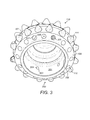
Figure 3 is an underside perspective view of one of the rotary cone cutters offigure 1 ; -
Figure 4 is a cross sectional view of the cone cutter offigure 3 ; -
Figure 5 is a further underside perspective cross sectional view of the cone cutter offigure 4 ; -
Figure 6 is a magnified cross sectional view the cone cutter offigure 4 to illustrate the relative alignment of an internal fluid flow passageway extending through the main body of the cone cutter offigure 4 according to a specific implementation of the present invention. - Referring to
figure 1 , a cuttinghead 100 is formed as a cutting bit intended for rotatory crushing drilling of rock. The cuttingbit 100 comprises a cuttingend 101 and an axiallyrearward attachment end 102 configured for attachment to one end of a drill string (not shown) forming part of a drill assembly operated via a drilling machine or rig (not shown) configured to provide axial and rotational drive to the cuttingbit 100 via the drill string. Cuttingbit 100 comprises threejournal arms 105 projecting axially forward fromattachment end 102 and being aligned slightly radially outward such that cuttingend 101 comprises a generally larger diameter thanattachment end 102. A generally conical shapedcone cutter 103 is mounted at one end of eachjournal arm 105 so as to be capable of rotation relative toarm 105 and independent rotation about a separate axis relative to the general rotation of cuttingbit 100 and the drill string (not shown). Referring tofigure 2 , a bearing assembly indicated generally byreference 200 is provided at anend 207 of eachjournal arm 105.Bearing assembly 200 may be mounted atjournal arm end 207 via a suitable spindle or axel (not shown) and comprises afirst raceways 201 located at a base region of bearingassembly 200 and asecond raceway 203 positioned at a tip region ofassembly 200. Athird raceway 202 is positioned between the first andsecond raceways roller bearings 204 is mounted atfirst raceway 201 and a second set ofroller bearings 206 is mounted atsecond raceway 203. A plurality ofball bearings 205 are mounted atthird raceway 202 so as to provide a minimum-friction bearing assembly 200 upon which is mountedcone cutter 103. - Referring to
figures 1 to 3 , eachcone cutter 103 comprises a generally cone or dome shaped configuration having a hollow structure. In particular, theannular cone cutter 103 comprises aninternal cavity 300 defined by a radially internal facingsurface 301. An opposed radially outward facing surface is indicated generally byreference 302 and represents a cutting face region ofcutter 103. In the axial direction,cone cutter 103 may be divided into axial sections at the outer facingsurface 302 and comprises aheel row 106, agauge row 107, adrive row 108 and an inner orapex region 109. A plurality of sets of cutting buttons (indicated generally by reference 104) are provided at each respective axial section including in particularheel row buttons 110, gauge buttons 111 (and 112), drivebuttons 113 andinner buttons 114. Each of the cuttingbuttons 104 comprises a working tip having a generally pointed configuration. However, as will be appreciated, eachcutting button 104 or specific set ofbuttons 104 may be semi-spherical, conical, ballistic, semi-ballistic or chisel shaped. Eachbutton 104 is formed from a wear resistant cemented carbide based material. Referring tofigures 3 and4 awall 401 of thecone cutter 103 is defined generally between the inward facingsurface 301 and the outward facingsurface 302. A plurality of generally cylindrical recesses are formed withinwall 401 at each axial section to extend radially inward from outward facingsurface 301. Eachrecess 307 accommodates acorresponding cutting button 104 via conventional welding and/or press/shrink fitting. - In order to cool the bearing
assembly 200 and in particular theroller bearings ball bearings 205, air is supplied through a conduit (not shown) within thejournal arms 105 to exit onto the region ofassembly 200 via an exit port (not shown).Cone cutter 103 is mounted at bearingassembly 200 via the positioning ofassembly 200 withincavity 300 such that the inward facingsurface 301 is orientated aroundbearings assembly 200 and the inward facingsurface 301. As illustrated infigure 3 , a base region ofcavity 300 is defined by anannular edge 306 formed as a mouth in the underside ofcone cutter 103.Mouth 306 is configured for positioning in close proximity to anannular shoulder 208 provided at a base region ofassembly 200 and formed atjournal arm end 207. Eachcone cutter 103 comprises a plurality of vents that extend through thecone wall 401 to exhaust the cooling air circulating around bearingassembly 200. In particular, a plurality ofpassageways 304 extend throughwall 401 between inward facingsurface 301 and outward facingsurface 302. Eachpassageway 304 is aligned transverse to a centrallongitudinal axis 400 extending throughcone cutter 103 with each passageway comprising anentry aperture 303 provided at inward facingsurface 301 and anexit aperture 305 provided at atrough region 406 of selected recesses 307. In particular, and according to the specific implementation of the present invention,passageways 304 are positioned to extend throughcutter wall 401 in the axial vicinity ofmouth 306. That is, eachpassageway entrance 303 is aligned axially approximately at thegauge row 107 whilst thepassageway exit aperture 305 is positioned approximately atheel row 106. According to the specific implementation, sixpassageways 304 are provided throughwall 401 and accordingly six respectiveheel row buttons 110 are modified so as to comprise a corresponding internal bore (or passageway) 402 extending between abase end 404 and an exit or cuttingend 403.Passageways entry aperture 303 atinternal cavity 300 and exiting at anaperture 405 provided at thebutton exit end 403. According to the specific implementation, a cross sectional area ofpassageway button 110 atbase end 404. - Referring to
figure 6 , the airflow vent passageways axis 400 so as to be declined downwardly fromaxis 400. As such,entry aperture 303 is positioned axially closer toapex region 109 relative to exitaperture 405 that is positioned at an axially similar position tomouth 306. Such an arrangement is advantageous to avoid penetration of particles and debris via a reverse direction throughpassageways cavity 300 that would otherwise contaminate and accelerate wear of bearingassembly 200. Additionally, and according to the specific implementation, a cross sectional area ofpassageways entry aperture 303 at inward facingsurface 301 to exitaperture 405 at the outer cuttingexit end 403 ofheel row button 110. However, according to further specific implementations, the cross sectional area ofpassageways apertures - Referring to
figure 6 , cutterexternal surface 302 atheel row region 106 is inclined relative toaxis 400 and is orientated at transverse angle b. In particular, according to the specific implementation b is substantially 50 to 55°.Passageways surface 302 atheel row 106 and are aligned at a declined angle a relative toaxis 400. According to the specific implementation, angle a is substantially in the range 140 to 150° relative toaxis 400. Accordingly,entry aperture 303 comprises a generally oval shape profile at inward facingsurface 301. Eachentry aperture 303 is aligned at the same axial position corresponding generally to the same axial position asgauge buttons 111. Positioningpassageways heel row section 106 is advantageous for a number of reasons. In particular, the exit airflow stream from eachbutton exit aperture 405 is directed axially rearward and radially outward relative toaxis 400. Accordingly, any dust or debris is prevented from accumulation at the region ofjournal arm shoulder 208 and in particular the interface region betweencone cutter mouth 306 andjournal arm 105. Such an arrangement prevents ingress of dust or particulates intocavity 300 and also eliminates accelerated frictional wear ofarm 105 andcutter 103 due to the accumulation of debris at the junction between these twocomponents - According to further specific implementations, additional or alternative fluid
flow exit passageways cone cutter wall 401. In particular, the fluidflow exit passageways gauge row 107, thedrive row 108 and/or theinner row 109. In such arrangements, specifically modifiedbuttons 104 would accordingly be provided in the same manner as described referring tofigures 1 to 6 and with reference to theheel row buttons 110.
Claims (15)
- A cone cutter (103) for mounting at a rotary cutting bit (100), the cone cutter (103) comprising:a generally cone-shaped main body having an annular wall (401) extending around a longitudinal axis (400) of the cutter (103), the wall (401) defined by a radially outward facing surface (302) and a radially inward facing surface (301), an internal cavity (300) defined by the inward facing surface (301) suitable for mounting on a bearing assembly (200) of a rotary cutting bit (100);a plurality of cutting buttons (104) mounted at the outward facing surface (302);characterised by:a plurality of vent passageways (304) extending through the wall (401) between the outward (302) and inward (301) facing surfaces to allow a flow of a fluid from within the cavity (300) to exit the main body through the wall (401).
- The cutter as claimed in claim 1 comprising a plurality of sections arranged axially at the outward facing surface (302), the sections comprising:a heel row (106) provided towards a base of the cone cutter (103) having heel buttons (110);a drive row (108) provided towards an apex (109) of the cone cutter (103) having drive buttons (113); anda gauge row (107) provided axially intermediate the heel (106) and drive (108) rows, the gauge row (107) comprising gauge buttons (111).
- The cutter as claimed in claim 2 wherein the passageways (304) emerge at the outward facing surface (302) within the heel row (106).
- The cutter as claimed in claim 3 wherein the passageways (304) continue through and emerge at respective heel buttons (110).
- The cutter as claimed in claims 3 or 4 wherein the passageways (304) comprise an elongate length extending between the outward (302) and inward (301) facing surfaces that is aligned at a declined angle through the wall (401) relative to the axis (400) such that the passageways (304) emerge at the inward facing surface (301) at an axial position closer to the apex (109) of the cone cutter (103) than a region where the passageways (304) emerge at the outward facing surface (302).
- The cutter as claimed in any one of claims 3 to 5 wherein an orientation of the passageways (304) is substantially perpendicular to the outward facing surface (302) at the heel row (106).
- The cutter as claimed in any one of claims 3 to 6 wherein the passageways (304) emerge at the inward facing surface (301) at substantially the same axial position corresponding to the position of the gauge row (107).
- The cutter as claimed in any one of claims 2 to 7 wherein the outward facing surface (302) at the heel row (106) is inclined relative to the axis (400) at an angle in the range 50 to 70°.
- The cutter as claimed in any one of claims 2 to 8 wherein at least some of the passageways (304) emerge at the outward facing surface (302) within the gauge row (107).
- The cutter as claimed in claim 9 wherein at least some of the passageways (304) continue through and emerge at respective gauge buttons (111).
- The cutter as claimed in any preceding claim wherein the passageways (304) comprise a length having a substantially uniform cross-sectional area between the inward (301) and outward (302) facing surfaces.
- The cutter as claimed in any preceding claim wherein a diameter of the passageways (304) is substantially half a diameter of a base (404) of each of the cutting buttons (104).
- The cutter as claimed in any preceding claim wherein the passageways (304) are uniformly distributed around the axis (400).
- A rotary cutting bit (100) for cutting rock comprising:at least one journal arm (105);a bearing assembly (200) mounted at the journal arm (105);a cutter (103) as claimed in any preceding claim mounted at the bearing assembly (200) via the cavity (300) so as to be capable of rotation relative to the journal arm (105).
- The bit as claimed in claim 14 comprising three journal arms (105) and three respective bearing assemblies (200) and cutters (103).
Priority Applications (2)
| Application Number | Priority Date | Filing Date | Title |
|---|---|---|---|
| EP14154781.0A EP2907964A1 (en) | 2014-02-12 | 2014-02-12 | Cone Cutter for Rotary Cutting Bit |
| PCT/EP2015/050800 WO2015121020A1 (en) | 2014-02-12 | 2015-01-16 | Cone cutter for rotary cutting bit |
Applications Claiming Priority (1)
| Application Number | Priority Date | Filing Date | Title |
|---|---|---|---|
| EP14154781.0A EP2907964A1 (en) | 2014-02-12 | 2014-02-12 | Cone Cutter for Rotary Cutting Bit |
Publications (1)
| Publication Number | Publication Date |
|---|---|
| EP2907964A1 true EP2907964A1 (en) | 2015-08-19 |
Family
ID=50072988
Family Applications (1)
| Application Number | Title | Priority Date | Filing Date |
|---|---|---|---|
| EP14154781.0A Withdrawn EP2907964A1 (en) | 2014-02-12 | 2014-02-12 | Cone Cutter for Rotary Cutting Bit |
Country Status (2)
| Country | Link |
|---|---|
| EP (1) | EP2907964A1 (en) |
| WO (1) | WO2015121020A1 (en) |
Citations (4)
| Publication number | Priority date | Publication date | Assignee | Title |
|---|---|---|---|---|
| US3193028A (en) | 1962-09-26 | 1965-07-06 | Exxon Production Research Co | Rotary drill bit |
| US3921735A (en) | 1975-02-27 | 1975-11-25 | Dresser Ind | Rotary rock bit with cone mouth air screen |
| US4421184A (en) | 1981-12-04 | 1983-12-20 | Hughes Tool Company | Rock bit with improved shirttail ventilation |
| US4688651A (en) | 1986-03-21 | 1987-08-25 | Dresser Industries, Inc. | Cone mouth debris exclusion shield |
-
2014
- 2014-02-12 EP EP14154781.0A patent/EP2907964A1/en not_active Withdrawn
-
2015
- 2015-01-16 WO PCT/EP2015/050800 patent/WO2015121020A1/en not_active Ceased
Patent Citations (4)
| Publication number | Priority date | Publication date | Assignee | Title |
|---|---|---|---|---|
| US3193028A (en) | 1962-09-26 | 1965-07-06 | Exxon Production Research Co | Rotary drill bit |
| US3921735A (en) | 1975-02-27 | 1975-11-25 | Dresser Ind | Rotary rock bit with cone mouth air screen |
| US4421184A (en) | 1981-12-04 | 1983-12-20 | Hughes Tool Company | Rock bit with improved shirttail ventilation |
| US4688651A (en) | 1986-03-21 | 1987-08-25 | Dresser Industries, Inc. | Cone mouth debris exclusion shield |
Also Published As
| Publication number | Publication date |
|---|---|
| WO2015121020A1 (en) | 2015-08-20 |
Similar Documents
| Publication | Publication Date | Title |
|---|---|---|
| CA2933136C (en) | Percussive rock drill bit with flushing grooves | |
| CA1320482C (en) | Drilling bit with improved trailing edge vent | |
| US20160090791A1 (en) | Percussive rock drill bit | |
| JP2016520008A (en) | Vacuum drilling system and method | |
| US10605006B2 (en) | Semi-sealed rotary drill tool | |
| CN107075913A (en) | The drill bit in the cutting face with depression | |
| EP0018394A1 (en) | ROLLING BODY BIT. | |
| WO2015121020A1 (en) | Cone cutter for rotary cutting bit | |
| JP4966717B2 (en) | Drilling tool | |
| US10626677B2 (en) | By-pass fluid passageway for drill tool | |
| JPH11347880A (en) | Chip removing device with air current for gun drill | |
| JP4435513B2 (en) | Cutting tools | |
| JPH08141813A (en) | Drill | |
| JP2006130616A (en) | Cutting tools | |
| US20210131187A1 (en) | Rock bit having cuttings channels for flow optimization | |
| SE432555B (en) | Method and slot cutter for making slots in concrete and similar material |
Legal Events
| Date | Code | Title | Description |
|---|---|---|---|
| PUAI | Public reference made under article 153(3) epc to a published international application that has entered the european phase |
Free format text: ORIGINAL CODE: 0009012 |
|
| 17P | Request for examination filed |
Effective date: 20140212 |
|
| AK | Designated contracting states |
Kind code of ref document: A1 Designated state(s): AL AT BE BG CH CY CZ DE DK EE ES FI FR GB GR HR HU IE IS IT LI LT LU LV MC MK MT NL NO PL PT RO RS SE SI SK SM TR |
|
| AX | Request for extension of the european patent |
Extension state: BA ME |
|
| STAA | Information on the status of an ep patent application or granted ep patent |
Free format text: STATUS: THE APPLICATION HAS BEEN WITHDRAWN |
|
| 18W | Application withdrawn |
Effective date: 20151207 |