EP2907673A1 - Bicycle hub with protective structure - Google Patents
Bicycle hub with protective structure Download PDFInfo
- Publication number
- EP2907673A1 EP2907673A1 EP15154532.4A EP15154532A EP2907673A1 EP 2907673 A1 EP2907673 A1 EP 2907673A1 EP 15154532 A EP15154532 A EP 15154532A EP 2907673 A1 EP2907673 A1 EP 2907673A1
- Authority
- EP
- European Patent Office
- Prior art keywords
- shell portion
- protective member
- top wall
- side walls
- ribs
- Prior art date
- Legal status (The legal status is an assumption and is not a legal conclusion. Google has not performed a legal analysis and makes no representation as to the accuracy of the status listed.)
- Withdrawn
Links
- 230000001681 protective effect Effects 0.000 title claims abstract description 58
- 239000000463 material Substances 0.000 claims abstract description 10
- 230000001154 acute effect Effects 0.000 claims abstract description 6
- 239000000047 product Substances 0.000 claims description 15
- 238000004519 manufacturing process Methods 0.000 claims description 9
- 238000000034 method Methods 0.000 claims description 4
- 238000000465 moulding Methods 0.000 claims description 4
- 239000012467 final product Substances 0.000 claims description 3
- 239000007787 solid Substances 0.000 claims description 3
- 238000007743 anodising Methods 0.000 claims description 2
- 230000005540 biological transmission Effects 0.000 description 4
- 239000002184 metal Substances 0.000 description 4
- 238000009434 installation Methods 0.000 description 2
- 239000000853 adhesive Substances 0.000 description 1
- 230000001070 adhesive effect Effects 0.000 description 1
- 230000000717 retained effect Effects 0.000 description 1
Images


Classifications
-
- B—PERFORMING OPERATIONS; TRANSPORTING
- B60—VEHICLES IN GENERAL
- B60B—VEHICLE WHEELS; CASTORS; AXLES FOR WHEELS OR CASTORS; INCREASING WHEEL ADHESION
- B60B27/00—Hubs
- B60B27/0015—Hubs for driven wheels
-
- B—PERFORMING OPERATIONS; TRANSPORTING
- B60—VEHICLES IN GENERAL
- B60B—VEHICLE WHEELS; CASTORS; AXLES FOR WHEELS OR CASTORS; INCREASING WHEEL ADHESION
- B60B27/00—Hubs
- B60B27/02—Hubs adapted to be rotatably arranged on axle
- B60B27/023—Hubs adapted to be rotatably arranged on axle specially adapted for bicycles
-
- B—PERFORMING OPERATIONS; TRANSPORTING
- B60—VEHICLES IN GENERAL
- B60B—VEHICLE WHEELS; CASTORS; AXLES FOR WHEELS OR CASTORS; INCREASING WHEEL ADHESION
- B60B27/00—Hubs
- B60B27/02—Hubs adapted to be rotatably arranged on axle
- B60B27/04—Hubs adapted to be rotatably arranged on axle housing driving means, e.g. sprockets
-
- B—PERFORMING OPERATIONS; TRANSPORTING
- B60—VEHICLES IN GENERAL
- B60B—VEHICLE WHEELS; CASTORS; AXLES FOR WHEELS OR CASTORS; INCREASING WHEEL ADHESION
- B60B2310/00—Manufacturing methods
- B60B2310/20—Shaping
- B60B2310/204—Shaping by moulding, e.g. injection moulding, i.e. casting of plastics material
-
- B—PERFORMING OPERATIONS; TRANSPORTING
- B60—VEHICLES IN GENERAL
- B60B—VEHICLE WHEELS; CASTORS; AXLES FOR WHEELS OR CASTORS; INCREASING WHEEL ADHESION
- B60B27/00—Hubs
- B60B27/02—Hubs adapted to be rotatably arranged on axle
- B60B27/04—Hubs adapted to be rotatably arranged on axle housing driving means, e.g. sprockets
- B60B27/047—Hubs adapted to be rotatably arranged on axle housing driving means, e.g. sprockets comprising a freewheel mechanisms
-
- B—PERFORMING OPERATIONS; TRANSPORTING
- B60—VEHICLES IN GENERAL
- B60B—VEHICLE WHEELS; CASTORS; AXLES FOR WHEELS OR CASTORS; INCREASING WHEEL ADHESION
- B60B2900/00—Purpose of invention
- B60B2900/10—Reduction of
- B60B2900/112—Costs
-
- B—PERFORMING OPERATIONS; TRANSPORTING
- B60—VEHICLES IN GENERAL
- B60B—VEHICLE WHEELS; CASTORS; AXLES FOR WHEELS OR CASTORS; INCREASING WHEEL ADHESION
- B60B2900/00—Purpose of invention
- B60B2900/20—Avoidance of
- B60B2900/212—Damage
-
- B—PERFORMING OPERATIONS; TRANSPORTING
- B60—VEHICLES IN GENERAL
- B60B—VEHICLE WHEELS; CASTORS; AXLES FOR WHEELS OR CASTORS; INCREASING WHEEL ADHESION
- B60B2900/00—Purpose of invention
- B60B2900/30—Increase in
- B60B2900/325—Reliability
-
- B—PERFORMING OPERATIONS; TRANSPORTING
- B60—VEHICLES IN GENERAL
- B60Y—INDEXING SCHEME RELATING TO ASPECTS CROSS-CUTTING VEHICLE TECHNOLOGY
- B60Y2200/00—Type of vehicle
- B60Y2200/10—Road Vehicles
- B60Y2200/13—Bicycles; Tricycles
Definitions
- the present invention relates to a bicycle hub, and more particularly to a protective structure for a bicycle hub.
- a hub cassette 7 has a plurality of ribs 71 on an outer periphery of the hub cassette 7 for engagement with a sprocket 8, as shown in FIG. 9 .
- the sprocket 8 is mounted around the hub cassette 7 and retained by the ribs 71.
- the ribs 71 may be worn easily for continuous riding since the sprocket 8 are generally harder than the ribs 71.
- each rib 71 would be worn to produce a notch 72 which causes the sprocket 8 cannot drive a bicycle hub effectively.
- a conventional bicycle hub further comprises a metal sheet 9 attached to the rib 71, as shown in FIG. 10 .
- the rib 71 has a recess 73 in a top thereof for accommodating the metal sheet 9.
- the metal sheet 9 is harder than the sprocket 8.
- the metal sheet 9 is fixed to the rib 71 by a plurality of screws 10 so as to reinforce the structure of the hub cassette 7.
- the configuration of the recess 73 will increase manufacturing cost and the screws 10 may be loosened during riding.
- a driving socket has a plurality of ribs extending axially on the outer surface thereof and at least one protection unit located between two of the ribs and has an engaging portion.
- a cover is engaged with the engaging portion and has a cover face and two sidewalls to form an engaging groove.
- the engaging portion has two transmission surfaces respectively located on two sides thereof and each transmission surface is gradually tapered toward a center of the driving socket.
- Each of the two sidewalls of the cover has an inclined surface corresponding to the respective transmission surface of the engaging portion for engagement between the engaging groove of the cover and the engaging groove.
- two sides of the engaging portion each has a positioning slot in the outer surface of the driving socket, wherein each sidewall of the cover has an extension engaged with the positioning slot to increase the contact area between the cover and the engaging portion.
- the configurations of the transmission surface and the positioning slot of the engaging portion will reduce the strength of the driving socket.
- the manufacturing processes of the engaging portion and the cover will increase manufacturing cost.
- the present invention has arisen to mitigate and/or obviate the disadvantages of the conventional bicycle hub.
- the main objective of the present invention is to provide an improved bicycle hub.
- a bicycle hub comprises a hub cassette and at least one protective member.
- the hub cassette has a driving portion and a shell portion connected to the driving portion.
- the shell portion has a plurality of ribs integrally formed on an outer periphery of the shell portion and extending axially from one end of the shell portion to the other end of the shell portion.
- the protective member is made of harder material than that of the ribs.
- the protective member is attached to at least one of the ribs of the shell portion.
- the protective member has a U-shaped cross section and defines a top wall and two side walls extending from a bottom of the top wall. The top wall and the two side walls define an engaging groove.
- an inner angle of the engaging groove between the top wall and each of the side walls is an acute angle originally.
- each of the two side walls of the protective member is flexible relative to the top wall of the protective member such that the two side walls of the protective member clamp two lateral walls of the associated rib.
- the bicycle hub further comprises another two protective members attached to the ribs of the shell portion, and the three protective members are disposed in triangular arrangement.
- Another object in accordance with the present invention is the provision of a method for manufacturing the bicycle hub above.
- the method comprises the steps of (a). cutting a solid rod into a plurality of rod pieces; (b). molding each of the rod pieces into a semi-product by a mold, wherein the semi-product has a driving portion, a shell portion, and a plurality of ribs integrally formed on an outer periphery of the shell portion; (c). removing excess material of the semi-product to form a hollow structure; (d). anodizing a surface of the semi-product to form a final product; and (e).
- the protective member made of harder material than that of the ribs and having a U-shaped cross section and defining a top wall and two side walls extending from a bottom of the top wall, the top wall and the two side walls defining an engaging groove, wherein an inner angle of the engaging groove between the top wall and each of the side walls being an acute angle originally, and the two side walls of the protective member are flexible to clamp two lateral walls of the associated rib.
- an installation of the protective member is manual, semi-automatic or fully automatic.
- another two protective members are attached to the ribs of the shell portion such that the three protective members are disposed in triangular arrangement.
- the hollow structure of the semi-product defines an assembling hole therethrough from the shell portion to the driving portion axially.
- a bicycle hub in accordance with a preferred embodiment of the present invention comprises a hub cassette 1 and at least one protective member 2.
- the hub cassette 1 has a driving portion 12, a shell portion 11 connected to the driving portion 12 and a flange 13 defined between the shell portion 11 and the driving portion 12.
- the driving portion 12 of the hub cassette has a plurality of recesses 121 around an outer periphery thereof.
- the shell portion 11 has a plurality of ribs 14 integrally formed on an outer periphery of the shell portion 11 and extending axially from one end of the shell portion 11 to the other end of the shell portion 11.
- the protective member 2 is made of harder material than that of sprockets and the hub cassette especially the ribs 14.
- the protective member 2 is attached to at least one of the ribs 14 of the shell portion 11.
- the protective member 2 has a U-shaped cross section and defines a top wall 23 and two side walls 22 extending from a bottom of the top wall 23. The top wall 23 and the two side walls 22 form an engaging groove 21.
- an inner angle of the engaging groove 21 between the top wall 23 and each of the side walls 22 is an acute angle originally, wherein each of the two side walls 22 of the protective member 2 is flexible relative to the top wall 23 of the protective member 2 such that the two side walls 22 of the protective member 2 clamp two lateral walls of the associated rib 14.
- the protective member 2 is fitted on the associated rib 14, and the inner angle between the top wall 23 and each side wall 22 is consistent with the angle of the associated rib 14 finally.
- the angle between the top wall 23 and each side wall 22 is changed to a right angle.
- the number of the protective member 2 is not limited in the present invention.
- the bicycle hub could further comprises another two protective members 2 such that the three protective members 2 are attached to the ribs 14 of the shell portion 11, and the three protective members 2 are disposed in triangular arrangement.
- the hub cassette 1 is hollow cylindrical in shape which defines an assembling hole 15 therethrough.
- the method comprises the steps of:
- step 105 at least one protective member 2 is attached to a related one of the ribs 14 of the shell portion 11.
- FIGS. 7-8 illustrate the operation of the protective member 2.
- the protective member 2 is leaned against one lateral wall of the associated rib 14 with one of the two side walls 22, and then the other side wall 22 is bent to buckle the opposite lateral wall of the associated rib 14 such that the protective member 2 clamps the associated rib 14 to retain on the hub cassette 1.
- the inner angle between the top wall 23 and each side wall 22 is consistent with the angle of the associated rib 14.
- the protective member 2 could be attached to the associated rib 14 by further adhesive.
- the installation of the protective member 2 could be manual, semi-automatic or fully automatic.
Landscapes
- Engineering & Computer Science (AREA)
- Mechanical Engineering (AREA)
- Tires In General (AREA)
Abstract
Description
- The present invention relates to a bicycle hub, and more particularly to a protective structure for a bicycle hub.
- Generally, a
hub cassette 7 has a plurality ofribs 71 on an outer periphery of thehub cassette 7 for engagement with asprocket 8, as shown inFIG. 9 . Thesprocket 8 is mounted around thehub cassette 7 and retained by theribs 71. However, theribs 71 may be worn easily for continuous riding since thesprocket 8 are generally harder than theribs 71. At the same time, eachrib 71 would be worn to produce anotch 72 which causes thesprocket 8 cannot drive a bicycle hub effectively. - In order to solve above problem, a conventional bicycle hub further comprises a
metal sheet 9 attached to therib 71, as shown inFIG. 10 . Wherein, therib 71 has arecess 73 in a top thereof for accommodating themetal sheet 9. Themetal sheet 9 is harder than thesprocket 8. Themetal sheet 9 is fixed to therib 71 by a plurality ofscrews 10 so as to reinforce the structure of thehub cassette 7. However, the configuration of therecess 73 will increase manufacturing cost and thescrews 10 may be loosened during riding. - Another type of bicycle hub is illustrated in
U.S. Pub. No. 2013/0076112 . In this bicycle hub, a driving socket has a plurality of ribs extending axially on the outer surface thereof and at least one protection unit located between two of the ribs and has an engaging portion. A cover is engaged with the engaging portion and has a cover face and two sidewalls to form an engaging groove. Specifically, the engaging portion has two transmission surfaces respectively located on two sides thereof and each transmission surface is gradually tapered toward a center of the driving socket. Each of the two sidewalls of the cover has an inclined surface corresponding to the respective transmission surface of the engaging portion for engagement between the engaging groove of the cover and the engaging groove. Furthermore, two sides of the engaging portion each has a positioning slot in the outer surface of the driving socket, wherein each sidewall of the cover has an extension engaged with the positioning slot to increase the contact area between the cover and the engaging portion. However, the configurations of the transmission surface and the positioning slot of the engaging portion will reduce the strength of the driving socket. Besides, the manufacturing processes of the engaging portion and the cover will increase manufacturing cost. - The present invention has arisen to mitigate and/or obviate the disadvantages of the conventional bicycle hub.
- The main objective of the present invention is to provide an improved bicycle hub.
- To achieve the objective, a bicycle hub comprises a hub cassette and at least one protective member. The hub cassette has a driving portion and a shell portion connected to the driving portion. The shell portion has a plurality of ribs integrally formed on an outer periphery of the shell portion and extending axially from one end of the shell portion to the other end of the shell portion. The protective member is made of harder material than that of the ribs. The protective member is attached to at least one of the ribs of the shell portion. The protective member has a U-shaped cross section and defines a top wall and two side walls extending from a bottom of the top wall. The top wall and the two side walls define an engaging groove. Specifically, an inner angle of the engaging groove between the top wall and each of the side walls is an acute angle originally. Wherein each of the two side walls of the protective member is flexible relative to the top wall of the protective member such that the two side walls of the protective member clamp two lateral walls of the associated rib.
- Preferably, the bicycle hub further comprises another two protective members attached to the ribs of the shell portion, and the three protective members are disposed in triangular arrangement.
- Another object in accordance with the present invention is the provision of a method for manufacturing the bicycle hub above.
- The method comprises the steps of (a). cutting a solid rod into a plurality of rod pieces; (b). molding each of the rod pieces into a semi-product by a mold, wherein the semi-product has a driving portion, a shell portion, and a plurality of ribs integrally formed on an outer periphery of the shell portion; (c). removing excess material of the semi-product to form a hollow structure; (d). anodizing a surface of the semi-product to form a final product; and (e). attaching at least one protective member to a related one of the ribs of the shell portion, the protective member made of harder material than that of the ribs and having a U-shaped cross section and defining a top wall and two side walls extending from a bottom of the top wall, the top wall and the two side walls defining an engaging groove, wherein an inner angle of the engaging groove between the top wall and each of the side walls being an acute angle originally, and the two side walls of the protective member are flexible to clamp two lateral walls of the associated rib.
- Preferably, in step (e), an installation of the protective member is manual, semi-automatic or fully automatic. In addition, another two protective members are attached to the ribs of the shell portion such that the three protective members are disposed in triangular arrangement. Moreover, in step (c), the hollow structure of the semi-product defines an assembling hole therethrough from the shell portion to the driving portion axially.
- Further benefits and advantages of the present invention will become apparent after a careful reading of the detailed description with appropriate reference to the accompanying drawings.
-
-
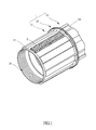
FIG. 1 is a perspective view of a bicycle hub with a protective member in accordance with a preferred embodiment of the present invention; -
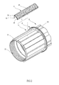
FIG. 2 is an exploded perspective view of the bicycle hub shown inFIG. 1 ; -
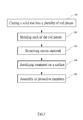
FIG. 3 is a flow chart of a manufacturing process of the bicycle hub of the present invention; -
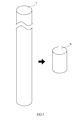
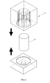
FIG. 4 illustrates a material preparing step of the bicycle hub of the present invention; -
FIG. 5 illustrates a molding step of the bicycle hub of the present invention; -
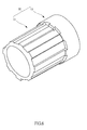
FIG. 6 is a perspective view of a semi-product from the molding step inFIG. 5 ; -
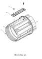
FIG. 7 illustrates at least one protective member attached to the shell portion of the present invention; -
FIG. 8 is a side view for showing the protective member attached to the shell portion of the present invention; -
FIG. 9 is prior art; and -
FIG. 10 is another prior art. - Referring to
FIGS. 1-2 , a bicycle hub in accordance with a preferred embodiment of the present invention comprises ahub cassette 1 and at least oneprotective member 2. - The
hub cassette 1 has adriving portion 12, ashell portion 11 connected to thedriving portion 12 and aflange 13 defined between theshell portion 11 and thedriving portion 12. Thedriving portion 12 of the hub cassette has a plurality ofrecesses 121 around an outer periphery thereof. Theshell portion 11 has a plurality ofribs 14 integrally formed on an outer periphery of theshell portion 11 and extending axially from one end of theshell portion 11 to the other end of theshell portion 11. Theprotective member 2 is made of harder material than that of sprockets and the hub cassette especially theribs 14. Theprotective member 2 is attached to at least one of theribs 14 of theshell portion 11. Theprotective member 2 has a U-shaped cross section and defines atop wall 23 and twoside walls 22 extending from a bottom of thetop wall 23. Thetop wall 23 and the twoside walls 22 form an engaginggroove 21. - Specifically, an inner angle of the engaging
groove 21 between thetop wall 23 and each of theside walls 22 is an acute angle originally, wherein each of the twoside walls 22 of theprotective member 2 is flexible relative to thetop wall 23 of theprotective member 2 such that the twoside walls 22 of theprotective member 2 clamp two lateral walls of the associatedrib 14. In this manner, theprotective member 2 is fitted on the associatedrib 14, and the inner angle between thetop wall 23 and eachside wall 22 is consistent with the angle of the associatedrib 14 finally. In the embodiment of the present invention, the angle between thetop wall 23 and eachside wall 22 is changed to a right angle. - Moreover, the number of the
protective member 2 is not limited in the present invention. For instance, the bicycle hub could further comprises another twoprotective members 2 such that the threeprotective members 2 are attached to theribs 14 of theshell portion 11, and the threeprotective members 2 are disposed in triangular arrangement. Furthermore, thehub cassette 1 is hollow cylindrical in shape which defines an assemblinghole 15 therethrough. - Referring to
FIGS. 3-8 , a method of manufacturing above bicycle hub is described below. The method comprises the steps of: - In
step 101, asolid rod 3 is cut into a plurality ofrod pieces 31, firstly. - In
step 102, each of therod pieces 31 is molded into a semi-product 32 by amold 5, wherein the semi-product 32 is formed with a drivingportion 12, ashell portion 11, and a plurality ofribs 14 integrally formed on an outer periphery of theshell portion 11. - In
step 103, excess material of the semi-product 32 is removed to form a hollow structure which defines an assemblinghole 15 therethrough from theshell portion 11 to the drivingportion 12 axially. - In
step 104, a surface of the semi-product 32 is anodized to form a final product. - Finally, in
step 105, at least oneprotective member 2 is attached to a related one of theribs 14 of theshell portion 11. - As mentioned previously, the two
side walls 22 of theprotective member 2 are flexible relative to thetop wall 23.FIGS. 7-8 illustrate the operation of theprotective member 2. Firstly, theprotective member 2 is leaned against one lateral wall of the associatedrib 14 with one of the twoside walls 22, and then theother side wall 22 is bent to buckle the opposite lateral wall of the associatedrib 14 such that theprotective member 2 clamps the associatedrib 14 to retain on thehub cassette 1. In this manner, the inner angle between thetop wall 23 and eachside wall 22 is consistent with the angle of the associatedrib 14. Particularly, theprotective member 2 could be attached to the associatedrib 14 by further adhesive. In addition, The installation of theprotective member 2 could be manual, semi-automatic or fully automatic.
Claims (6)
- A bicycle hub, comprising a hub cassette (1) having a driving portion (12) and a shell portion (11) connected to the driving portion (12), the shell portion (11) having a plurality of ribs (14) integrally formed on an outer periphery of the shell portion (11) and extending axially from one end of the shell portion (11) to the other end of the shell portion (11); characterized in that the bicycle hub further comprises at least one protective member (2) made of harder material than that of the ribs, the protective member (2) attached to at least one of the ribs (14) of the shell portion (11), the protective member (2) having a U-shaped cross section and defining a top wall (23) and two side walls (22) extending from a bottom of the top wall (23), the top wall (23) and the two side walls (22) defining an engaging groove (21), an inner angle of the engaging groove (21) between the top wall (23) and each of the side walls (22) being an acute angle originally; wherein each of the two side walls (22) of the protective member (2) is flexible relative to the top wall (23) of the protective member (2) such that the two side walls (22) of the protective member (2) clamp the associated rib (14).
- The bicycle hub as claimed in claim 1, further comprising another two protective members (2) attached to the ribs (14) of the shell portion (11), wherein the three protective members (2) are disposed in triangular arrangement.
- The bicycle hub as claimed in claim 1, wherein the hub cassette (1) is hollow cylindrical in shape which defines an assembling hole (15) therethrough.
- A method of manufacturing a bicycle hub, comprising the steps of:(a). cutting a solid rod into a plurality of rod pieces;(b). molding each of the rod pieces into a semi-product by a mold, wherein the semi-product has a driving portion (12), a shell portion (11), and a plurality of ribs integrally formed on an outer periphery of the shell portion (11);(c). removing excess material of the semi-product to form a hollow structure;(d). anodizing a surface of the semi-product to form a final product; characterized in that
the method further comprising the step of (e). attaching at least one protective member (2) to a related one of the ribs (14) of the shell portion (11), the protective member (2) made of harder material than that of the ribs (14) and having a U-shaped cross section and defining a top wall (23) and two side walls (22) extending from a bottom of the top wall (23), the top wall (23) and the two side walls (22) defining an engaging groove (21), wherein an inner angle of the engaging groove (21) between the top wall (23) and each of the side walls (22) being an acute angle originally, and the two side walls (22) of the protective member (2) are flexible to clamp the associated rib (14). - The method of manufacturing the bicycle hub as claimed in claim 4, wherein in step (e), another two protective members (2) are attached to the ribs (14) of the shell portion (11) such that the three protective members (2) are disposed in triangular arrangement.
- The method of manufacturing the bicycle hub as claimed in claim 4, wherein in step (c), the hollow structure of the semi-product defines an assembling hole (15) therethrough from the shell portion (11) to the driving portion (12) axially.
Applications Claiming Priority (1)
| Application Number | Priority Date | Filing Date | Title |
|---|---|---|---|
| TW103202458U TWM489096U (en) | 2014-02-12 | 2014-02-12 | Gear body structure |
Publications (1)
| Publication Number | Publication Date |
|---|---|
| EP2907673A1 true EP2907673A1 (en) | 2015-08-19 |
Family
ID=52464266
Family Applications (1)
| Application Number | Title | Priority Date | Filing Date |
|---|---|---|---|
| EP15154532.4A Withdrawn EP2907673A1 (en) | 2014-02-12 | 2015-02-10 | Bicycle hub with protective structure |
Country Status (2)
| Country | Link |
|---|---|
| EP (1) | EP2907673A1 (en) |
| TW (1) | TWM489096U (en) |
Cited By (3)
| Publication number | Priority date | Publication date | Assignee | Title |
|---|---|---|---|---|
| GB2552596A (en) * | 2016-07-28 | 2018-01-31 | Christianson Systems Inc | Cassette driver for a freewheel hub |
| US10113597B2 (en) | 2016-04-04 | 2018-10-30 | Christianson Systems, Inc. | Cassette driver for a freewheel hub |
| US10119579B2 (en) | 2016-04-04 | 2018-11-06 | Christianson Systems, Inc. | Cassette driver for a freewheel hub |
Citations (3)
| Publication number | Priority date | Publication date | Assignee | Title |
|---|---|---|---|---|
| US3191735A (en) * | 1963-02-28 | 1965-06-29 | Borg Warner | Spline liner |
| US20120139327A1 (en) * | 2010-12-02 | 2012-06-07 | Ching-Shu Chen | Bicycle Hub Assembly |
| US20130076112A1 (en) | 2011-09-28 | 2013-03-28 | Kunshan Henry Metal Technology Co., Ltd. | Protection unit for driving socket of hub |
-
2014
- 2014-02-12 TW TW103202458U patent/TWM489096U/en not_active IP Right Cessation
-
2015
- 2015-02-10 EP EP15154532.4A patent/EP2907673A1/en not_active Withdrawn
Patent Citations (3)
| Publication number | Priority date | Publication date | Assignee | Title |
|---|---|---|---|---|
| US3191735A (en) * | 1963-02-28 | 1965-06-29 | Borg Warner | Spline liner |
| US20120139327A1 (en) * | 2010-12-02 | 2012-06-07 | Ching-Shu Chen | Bicycle Hub Assembly |
| US20130076112A1 (en) | 2011-09-28 | 2013-03-28 | Kunshan Henry Metal Technology Co., Ltd. | Protection unit for driving socket of hub |
Cited By (4)
| Publication number | Priority date | Publication date | Assignee | Title |
|---|---|---|---|---|
| US10113597B2 (en) | 2016-04-04 | 2018-10-30 | Christianson Systems, Inc. | Cassette driver for a freewheel hub |
| US10119579B2 (en) | 2016-04-04 | 2018-11-06 | Christianson Systems, Inc. | Cassette driver for a freewheel hub |
| GB2552596A (en) * | 2016-07-28 | 2018-01-31 | Christianson Systems Inc | Cassette driver for a freewheel hub |
| GB2552596B (en) * | 2016-07-28 | 2021-12-01 | Christianson Systems Inc | Cassette driver for a freewheel hub |
Also Published As
| Publication number | Publication date |
|---|---|
| TWM489096U (en) | 2014-11-01 |
Similar Documents
| Publication | Publication Date | Title |
|---|---|---|
| US9415634B2 (en) | Bicycle hub with protective structure | |
| USD934153S1 (en) | Motorcycle tire | |
| USD905767S1 (en) | Refrigerator | |
| USD816598S1 (en) | Tire | |
| USD768057S1 (en) | Tire tread | |
| USD772790S1 (en) | Tire tread | |
| EP2907673A1 (en) | Bicycle hub with protective structure | |
| USD918126S1 (en) | Tire | |
| USD859291S1 (en) | Motorcycle tire | |
| USD957316S1 (en) | Tire | |
| US8801109B2 (en) | Protection unit for driving socket of hub | |
| USD796423S1 (en) | Tire tread | |
| USD878286S1 (en) | Tire | |
| USD819558S1 (en) | Tire | |
| USD776607S1 (en) | Tire tread | |
| KR20110090249A (en) | Shaver cartridges | |
| USD859292S1 (en) | Motorcycle tire | |
| USD870022S1 (en) | Motorcycle tire | |
| USD943506S1 (en) | Tire | |
| KR101826227B1 (en) | Steel grating and manufacturing method thereof | |
| EP2666731B1 (en) | Handle assembly for an airtight container | |
| US10486465B2 (en) | Reinforcement for a hub ratchet base | |
| EP3674678B1 (en) | Pressure gauge | |
| JP5483370B2 (en) | Replacement tooth sprocket | |
| US20140021004A1 (en) | Ratchet base structure for a bicycle |
Legal Events
| Date | Code | Title | Description |
|---|---|---|---|
| PUAI | Public reference made under article 153(3) epc to a published international application that has entered the european phase |
Free format text: ORIGINAL CODE: 0009012 |
|
| AK | Designated contracting states |
Kind code of ref document: A1 Designated state(s): AL AT BE BG CH CY CZ DE DK EE ES FI FR GB GR HR HU IE IS IT LI LT LU LV MC MK MT NL NO PL PT RO RS SE SI SK SM TR |
|
| AX | Request for extension of the european patent |
Extension state: BA ME |
|
| 17P | Request for examination filed |
Effective date: 20160218 |
|
| RBV | Designated contracting states (corrected) |
Designated state(s): AL AT BE BG CH CY CZ DE DK EE ES FI FR GB GR HR HU IE IS IT LI LT LU LV MC MK MT NL NO PL PT RO RS SE SI SK SM TR |
|
| STAA | Information on the status of an ep patent application or granted ep patent |
Free format text: STATUS: THE APPLICATION IS DEEMED TO BE WITHDRAWN |
|
| 18D | Application deemed to be withdrawn |
Effective date: 20170901 |