EP2905986A1 - Method and device for testing moving speed of terminal - Google Patents
Method and device for testing moving speed of terminal Download PDFInfo
- Publication number
- EP2905986A1 EP2905986A1 EP13842167.2A EP13842167A EP2905986A1 EP 2905986 A1 EP2905986 A1 EP 2905986A1 EP 13842167 A EP13842167 A EP 13842167A EP 2905986 A1 EP2905986 A1 EP 2905986A1
- Authority
- EP
- European Patent Office
- Prior art keywords
- delay path
- variations
- time
- pilot
- receiving end
- Prior art date
- Legal status (The legal status is an assumption and is not a legal conclusion. Google has not performed a legal analysis and makes no representation as to the accuracy of the status listed.)
- Granted
Links
Images

Classifications
-
- H—ELECTRICITY
- H04—ELECTRIC COMMUNICATION TECHNIQUE
- H04W—WIRELESS COMMUNICATION NETWORKS
- H04W64/00—Locating users or terminals or network equipment for network management purposes, e.g. mobility management
- H04W64/006—Locating users or terminals or network equipment for network management purposes, e.g. mobility management with additional information processing, e.g. for direction or speed determination
-
- G—PHYSICS
- G01—MEASURING; TESTING
- G01S—RADIO DIRECTION-FINDING; RADIO NAVIGATION; DETERMINING DISTANCE OR VELOCITY BY USE OF RADIO WAVES; LOCATING OR PRESENCE-DETECTING BY USE OF THE REFLECTION OR RERADIATION OF RADIO WAVES; ANALOGOUS ARRANGEMENTS USING OTHER WAVES
- G01S11/00—Systems for determining distance or velocity not using reflection or reradiation
- G01S11/02—Systems for determining distance or velocity not using reflection or reradiation using radio waves
- G01S11/06—Systems for determining distance or velocity not using reflection or reradiation using radio waves using intensity measurements
-
- H—ELECTRICITY
- H04—ELECTRIC COMMUNICATION TECHNIQUE
- H04L—TRANSMISSION OF DIGITAL INFORMATION, e.g. TELEGRAPHIC COMMUNICATION
- H04L27/00—Modulated-carrier systems
- H04L27/26—Systems using multi-frequency codes
- H04L27/2601—Multicarrier modulation systems
-
- H—ELECTRICITY
- H04—ELECTRIC COMMUNICATION TECHNIQUE
- H04W—WIRELESS COMMUNICATION NETWORKS
- H04W24/00—Supervisory, monitoring or testing arrangements
- H04W24/08—Testing, supervising or monitoring using real traffic
Definitions
- the present invention relates to the field of mobile communications and particularly to a method and device for testing the moving speed of a terminal.
- a terminal may move at a high speed so that a considerable Doppler shift will occur, and the amplitude of a signal may fade rapidly and the phase of the signal may vary rapidly particularly in a multi-path scenario, thus deteriorating the performance of the system. It is thus necessary for a receiving end to adjust adaptively algorithms related to channel estimation and signal detection dependent upon the current moving speed of the terminal, and to this end, an algorithm to measure the speed accurately is required to support such an adaptive adjustment strategy. At present there are the following algorithms to measure the speed:
- the crossing rate algorithm is very simple in principle and easy to perform and has been widely applied in real communication systems.
- the Doppler shift may result in a temporally fluctuating signal so that generally there is a deep fading of the amplitude of the signal once the terminal moves over a distance of half the wavelength.
- the number of times Le that the level fades per unit time can be counted to thereby estimate the speed.
- a general problem with the crossing rate algorithm is how to count Le accurately. There may be a large number of observable burrs of the signal in time-domain being affected by noise and the channel. The number of times that the level fades can be counted accurately only after the signal is de-noised, de-burred, etc. Moreover the accuracy in estimation of the speed may also be affected by the statistic operation for the level crossing rate.
- the signal has to be preprocessed in the algorithm nevertheless at low precision.
- the count characteristic in the correlation algorithm can only be applicable to the Rayleigh channel but not to the Rician channel, so the algorithm has to be revised by the Rician factor in the other scenarios, but the Rician factor K may not be easy to determine, thus complicating the algorithm.
- the Bessel curve is not a monotonic function, and in order to estimate the speed accurately, 2 ⁇ m ⁇ ⁇ 4 shall be guaranteed, and if there is a significant Doppler dispersion ⁇ m at a high speed, then the Doppler dispersion can be estimated only if the value of ⁇ is very small, so that the correlation algorithm may be restricted greatly at a high speed.
- the statistic operation for autocorrelation may also affect the precision of the algorithm.
- Embodiments of the invention provide a method for testing a moving speed of a terminal so as to measure the moving speed of the terminal according to pilots, and noise power.
- An embodiment of the invention provides a method for testing a moving speed of a terminal, the method including:
- An embodiment of the invention provides a device for testing a moving speed of a terminal, the device including:
- the receiving end receives a signal including a pilot sequence transmitted by the transmitting end; the receiving end determines a time-domain channel estimation value corresponding to each pilot symbol being transmitted, in the pilot sequence according to a known pilot sequence and the signal including the pilot sequence and selects a delay path according to the time-domain channel estimation values; and the receiving end determines the moving speed of the terminal according to the delay path selected in a preset length of time.
- the receiving end in the embodiments of the invention can measure the moving speed of the terminal according to the pilots and the noise power, and with this method, the calculation can be performed simply using the available received pilots, and the statistic of the delay path can be made simply, accurately and adaptively to easily get a high precision without being affected by any factor of the algorithm; with this method, only the statistic of the channel response values of the frequencies at which the pilots are located will be made to thereby lower an effort of calculation; and moreover the algorithm with a low delay can be applicable to scenarios at different delays and different speeds, and the process of testing the speed can be performed before the channel estimation is performed on the signal, and the result thereof can be applicable directly to the current channel estimation and signal detection processes.
- Embodiments of the invention provide a method for testing a moving speed of a terminal so as to measure the moving speed of the terminal according to pilot and noise power to thereby improve the precision in measurement.
- a method for testing a moving speed of a terminal includes:
- a delay path There are typically a number of transmission paths with different delays in transmission over a real space channel, and these different transmission paths are embodied as corresponding power values at different points of time in time-domain channel estimation, where a peak point with a power value above some threshold is referred to as a delay path.
- the operation S101 furthermore includes: the receiving end determines noise power when the signal including the pilot sequence is received, and a signal to noise ratio corresponding to the noise power; and the operation S102 is performed by the receiving end upon determining that the signal to noise ratio is above a first preset threshold, that is, furthermore the noise power when the signal including the pilot sequence is received and the signal to noise ratio corresponding to the noise power is required to be determined, and it is determined that the signal to noise ratio is above the first preset threshold, before the operation S102.
- the receiving end determines a frequency-domain channel estimation value corresponding to each pilot symbol being transmitted, in the pilot sequence, according to the known pilot sequence and the signal including the pilot sequence;
- the receiving end determines the time-domain channel estimation value corresponding to each pilot symbol according to the frequency-domain channel estimation value corresponding to the pilot symbol.
- the delay path is selected in the operation S102 as follows:
- the receiving end selects the delay path with the highest power for each pilot symbol
- the receiving end determines the location of the selected delay path with the highest power, and if the receiving end determines that locations of delay paths selected for pilot symbols at the same frequency-domain location are different,
- the receiving end determines one of the locations of the delay paths and determines the delay path corresponding to the location as the delay path selected for the pilot symbols at the same frequency-domain location, or selects the location of the delay path maximizing the sum of power of the delay paths corresponding to the pilots at the same frequency-domain location and determines the delay path corresponding to the location as the delay path selected for the pilot symbols at the same frequency-domain location.
- the location of the delay path refers to a point of time corresponding to the delay path in time-domain channel estimation.
- the operation S103 includes: the receiving end determines an average variation of the delay path selected in the preset length of time according to the delay path in the preset length of time; and
- the receiving end determines the moving speed of the terminal according to the average variation of the delay path.
- the receiving end determines the average of the variation of the delay path selected in the preset length of time according to the delay path in the preset length of time as follows:
- the receiving end groups together a plurality of pilot symbols at the same frequency-domain location determined in the preset length of time and calculates variations of the delay path of the pilot symbols spaced by a preset number of Orthogonal Frequency Division Multiplexing (OFDM) symbols in the respective groups;
- OFDM Orthogonal Frequency Division Multiplexing
- the receiving end determines the averages of the variations of the delay path in the respective groups respectively according to the variations of the delay path of the pilot symbols spaced by the preset number of OFDM symbols in the respective groups;
- the receiving end determines the average variation of the delay path in the preset length of time according to the averages of the variations of the delay path in the respective groups.
- the receiving end increases the preset number of spacing OFDM symbols and recalculates the average of the variation of the delay path.
- the receiving end determines the moving speed of the terminal according to the average variation of the delay path as follows:
- the receiving end determines the moving speed of the terminal according to the average variation of the delay path, and a pre-stored relationship between the average variation of the delay path and the moving speed of the terminal.
- the receiving end determines the noise power when the signal including the pilot sequence is received;
- the receiving end determines the average noise power in the preset length of time according to the noise power; and
- the receiving end determines the averages of the variations of the delay path in the respective groups respectively according to the variations of the delay path of the pilot symbols spaced by the preset number of OFDM symbols in the respective groups, the method further includes:
- the receiving end revises the average of the variation of the delay path by the average noise power in the preset length of time.
- the invention can also be applicable to a communication system in which a signal including a pilot is transmitted, e.g., a Time Division-Synchronous Code Division Multiple Access (TD-SCDMA), a Long Term Evolution (LTE), a Long Term Evolution-Advanced (LTE-A), etc. Since the data transmitted in the pilot is known, an accurate channel estimation value can be derived directly in the simple Least Square (LS) method, and since the speed is measured before channel estimation is performed on the signal, the current speed measurement result can be applied directly to the current channel estimation and signal detection processes.
- LS Least Square
- the transmitting end can be a base station, and the receiving end can be a terminal; or the transmitting end can be a terminal, and the receiving end can be a base station.
- the moving speed of the terminal can be measured particularly in the following steps:
- the receiving end obtains and stores noise power P noise of the receiving end upon reception of the signal.
- the receiving end determines power of the received signal and determines a corresponding signal to noise ratio according to the power of the received signal and the noise power. Since the precision in measurement may be degraded at a low signal to noise ratio, it can be specified for the signal to noise ratio that the precision in measurement is determined to be satisfactory when the signal to noise ratio is above a first preset threshold, and at this time measurement of the speed can be initiated; otherwise, a default or null value can be applied.
- the first and third columns of pilot symbols are the same, and the frequency-domain locations of the second and fourth columns of pilot symbols are the same, the first and third columns are grouped together, and the second and fourth columns are grouped together, and the variations of the delay path of the adjacent pilot symbols are calculated.
- a smoothing process can be further performed to remove the sub-frames for the statistic operation, with errors above a third threshold and then average the results, particularly as follows: the averages E' [( ⁇ H ') 2 ( k ) ] of the respective variations in the respective groups of ( ⁇ H ') 2 ( k ) are calculated respectively; the squares of the differences ⁇ 1 , ⁇ 2 , ⁇ 3 ;
- ⁇ n between the respective variations in each group of ( ⁇ H' ) 2 ( k ) and the average E' [( ⁇ H' ) 2 ( k ) ] are calculated; the sub-frames for the statistic operation corresponding to ⁇ m (1 ⁇ m ⁇ n ) above the third threshold are removed; and the variations corresponding to the remaining sub-frames in the respective groups of ( ⁇ H' ) 2 ( k ) are averaged again to get the averages E [( ⁇ H' ) 2 ( k ) ] of the variations of the delay path in the respective groups.
- a threshold is applied to the measurement, and if the value of the measured speed is below a second preset threshold, e.g., 30km/h, then the spacing between each group of pilots for calculation is increased, the statistic operation is performed again, and the measurement result is processed.
- a second preset threshold e.g. 30km/h
- pilot symbols at the same frequency-domain are grouped together so that the pilots in the group are spaced by 7 OFDM symbols, and if the measurement result is below the threshold, then a low-speed scenario can be determined, and at this time if pilot symbols spaced by one sub-frame are grouped together, then the pilots in the group are spaced by 14 OFDM symbols, i.e., twice the original spacing, and accordingly the measurement result obtained by referring to a lookup table or the substitution into the equation is also halved.
- pilot symbols spaced by one radio frame are grouped together, then the pilots in the group are spaced by 140 OFDM symbols, i.e., 20 times the original spacing, and accordingly the measurement result obtained by referring to a lookup table or the substitution into the equation is also reduced by a factor of 20, i.e., the real speed.
- ⁇ H can be calculated in the simulation particularly as follows:
- the value of M shall be large enough to guarantee higher precision of the created equation or table and consequentially the precision in measurement, where it can be judged whether the value of M is sufficiently large by judging whether the statistic result of ⁇ H is stable as M is further increased (the M is typically on the order of a thousand of frames or more in the LTE system); and the value of N is decided by the acceleration available to the UE and the precision required for the measurement.
- the value of N shall be set small (in the LTE system, if the highest acceleration is 2.8 km / s 2 , then a potentially introduced error in measurement is 10 km / s 2 at N of 100) so that a delay of the measurement value relative to the real value and consequentially the resulting largest error in measurement will not be too large.
- the speed can be measured using the delay path in a simple calculation procedure at a low delay, applicable to scenarios at different delays and different speeds, and the process of testing the speed can be performed before channel estimation is performed on the signal, the result thereof can be applicable directly to the current channel estimation and signal detection processes; and moreover since the result is revised in view of the noise and removing the variations of the delay path with significant mean squared errors, etc., thereby improving the precision in measurement of the speed.
- the precision of the measurement result can be guaranteed even at a low speed by increasing the spacing between the pilots while performing the calculation.
- CMMB China Mobile Multimedia Broadcasting
- noise reduction can be performed on the received signal in the frequency-domain before this operation to thereby improve the precision of data.
- ⁇ even ⁇ H ⁇ even 2 - 2 ⁇ ⁇ 2 E h 0 n 0 ⁇ E h 2 n 0
- ⁇ odd ⁇ H ⁇ odd 2 - 2 ⁇ ⁇ 2 E h 1 n 1 ⁇ E h 3 n 1 .
- a signal to noise ratio or channel delay information will not be distinguished in the table, and the number of stored tables can be determined according to the number of levels into which the measured speed is divided, e.g., M levels, where only (M-1) ⁇ H - V relationship tables need to be stored.
- the lowest measured speed can be determined directly without referring to any relationship table.
- N, M, and the levels of the speed can be selected as required for the precision in measurement.
- a device for testing a moving speed of a terminal includes:
- the device further includes a first noise determining module configured to determine noise power when the signal including the pilot sequence is received, and to determine a signal to noise ratio corresponding to the noise power according to the noise power.
- a first noise determining module configured to determine noise power when the signal including the pilot sequence is received, and to determine a signal to noise ratio corresponding to the noise power according to the noise power.
- the delay path determining module 42 is configured:
- the delay path determining module 42 includes:
- the speed determining module 43 includes:
- the delay path calculating unit 53 is configured:
- the speed calculating unit 54 is configured:
- the delay path calculating unit 53 is further configured:
- the device further includes:
- the delay path calculating unit 53 configured to determine the averages of the variations of the delay path in the respective groups respectively according to the variations of the delay path of the pilot symbols spaced by the preset number of OFDM symbols in the respective groups is configured:
- the receiving end receives a signal including a pilot sequence transmitted by the transmitting end; the receiving end determines a channel response function corresponding to the signal of each pilot sequence being transmitted, according to a pre-stored pilot sequence and the signal including the pilot sequence and determines a corresponding delay path according to the channel response function; and the receiving end determines the moving speed of the terminal according to the delay path.
- the embodiments of the invention provide a method and device for testing a moving speed of a terminal so as to measure the moving speed of the terminal according to pilots and noise power so as to improve the precision in measurement.
- the embodiments of the invention can be embodied as a method, a system or a computer program product. Therefore the invention can be embodied in the form of an all-hardware embodiment, an all-software embodiment or an embodiment of software and hardware in combination. Furthermore the invention can be embodied in the form of a computer program product embodied in one or more computer useable storage mediums (including but not limited to a disk memory, a CD-ROM, an optical memory, etc.) in which computer useable program codes are contained.
- a computer useable storage mediums including but not limited to a disk memory, a CD-ROM, an optical memory, etc.
- These computer program instructions can also be stored into a computer readable memory capable of directing the computer or the other programmable data processing device to operate in a specific manner so that the instructions stored in the computer readable memory create an article of manufacture including instruction means which perform the functions specified in the flow(s) of the flow chart and/or the block(s) of the block diagram.
- These computer program instructions can also be loaded onto the computer or the other programmable data processing device so that a series of operational steps are performed on the computer or the other programmable data processing device to create a computer implemented process so that the instructions executed on the computer or the other programmable device provide steps for performing the functions specified in the flow(s) of the flow chart and/or the block(s) of the block diagram.
Landscapes
- Engineering & Computer Science (AREA)
- Computer Networks & Wireless Communication (AREA)
- Signal Processing (AREA)
- Physics & Mathematics (AREA)
- General Physics & Mathematics (AREA)
- Radar, Positioning & Navigation (AREA)
- Remote Sensing (AREA)
- Mobile Radio Communication Systems (AREA)
Abstract
Description
- This application claims the benefit of Chinese Patent Application No.
201210365083.5 - The present invention relates to the field of mobile communications and particularly to a method and device for testing the moving speed of a terminal.
- In a communication system, a terminal may move at a high speed so that a considerable Doppler shift will occur, and the amplitude of a signal may fade rapidly and the phase of the signal may vary rapidly particularly in a multi-path scenario, thus deteriorating the performance of the system. It is thus necessary for a receiving end to adjust adaptively algorithms related to channel estimation and signal detection dependent upon the current moving speed of the terminal, and to this end, an algorithm to measure the speed accurately is required to support such an adaptive adjustment strategy. At present there are the following algorithms to measure the speed:
- The crossing rate algorithm is very simple in principle and easy to perform and has been widely applied in real communication systems. The Doppler shift may result in a temporally fluctuating signal so that generally there is a deep fading of the amplitude of the signal once the terminal moves over a distance of half the wavelength. The number of times Le that the level fades per unit time can be counted to thereby estimate the speed. With a carrier frequency fc and the velocity of light c, the speed can be estimated as v=c/fc*Le.
- The moving speed may result in the Doppler dispersion of the signal in the frequency-domain, and there is the following relationship between time-domain autocorrelation of the received signal and the Doppler dispersion over a Rayleigh channel:

Where ƒm represents the largest Doppler dispersion, τ represents a correlation time, ρx (τ) represents autocorrelation of the signal, σ 2 represents noise power, and J 0(·) represents a Bessel function of the first kind of order zero with a curve as illustrated inFig.1 . Thus a statistic of a time-domain autocorrelation value of the signal is made from the time-domain autocorrelation characteristic of the signal, and the Doppler dispersion ƒ m is estimated against a lookup table of Bessel function curves to thereby estimate the moving speed. The equation (1) has to be revised for use in view of a direction of arrival distributed non-uniformly and affected by a Rician factor K over a Rician channel. - A general problem with the crossing rate algorithm is how to count Le accurately. There may be a large number of observable burrs of the signal in time-domain being affected by noise and the channel. The number of times that the level fades can be counted accurately only after the signal is de-noised, de-burred, etc. Moreover the accuracy in estimation of the speed may also be affected by the statistic operation for the level crossing rate. The signal has to be preprocessed in the algorithm nevertheless at low precision.
- The count characteristic in the correlation algorithm can only be applicable to the Rayleigh channel but not to the Rician channel, so the algorithm has to be revised by the Rician factor in the other scenarios, but the Rician factor K may not be easy to determine, thus complicating the algorithm. Moreover the Bessel curve is not a monotonic function, and in order to estimate the speed accurately, 2πƒ m τ<4 shall be guaranteed, and if there is a significant Doppler dispersion ƒm at a high speed, then the Doppler dispersion can be estimated only if the value of τ is very small, so that the correlation algorithm may be restricted greatly at a high speed. Moreover the statistic operation for autocorrelation may also affect the precision of the algorithm.
- Furthermore with both of the methods above, generally after channel estimation is performed on respective received signals, a statistic of derived channel response values throughout the bandwidth has to be made with a considerable effort of calculation, and a current calculation result can only be applicable, at some delay in time, to next channel estimation and channel detection
- Embodiments of the invention provide a method for testing a moving speed of a terminal so as to measure the moving speed of the terminal according to pilots, and noise power.
- An embodiment of the invention provides a method for testing a moving speed of a terminal, the method including:
- receiving, by a receiving end, a signal including a pilot sequence transmitted by a transmitting end;
- determining, by the receiving end, a time-domain channel estimation value corresponding to each pilot symbol being transmitted, in the pilot sequence according to a known pilot sequence and the signal including the pilot sequence and selecting a delay path according to the time-domain channel estimation values; and
- determining, by the receiving end, the moving speed of the terminal according to the delay path selected in a preset length of time.
- An embodiment of the invention provides a device for testing a moving speed of a terminal, the device including:
- a communicating module configured to receive a signal including a pilot sequence transmitted by a transmitting end;
- a delay path determining module configured to determine a time-domain channel estimation value corresponding to each pilot symbol being transmitted, in the pilot sequence according to a known pilot sequence and the signal including the pilot sequence and to select a delay path according to the time-domain channel estimation values; and
- a speed determining module configured to determine the moving speed of the terminal according to the delay path selected in a preset length of time.
- As can be apparent from the technical solutions above, in the embodiments of the invention, the receiving end receives a signal including a pilot sequence transmitted by the transmitting end; the receiving end determines a time-domain channel estimation value corresponding to each pilot symbol being transmitted, in the pilot sequence according to a known pilot sequence and the signal including the pilot sequence and selects a delay path according to the time-domain channel estimation values; and the receiving end determines the moving speed of the terminal according to the delay path selected in a preset length of time. Thus the receiving end in the embodiments of the invention can measure the moving speed of the terminal according to the pilots and the noise power, and with this method, the calculation can be performed simply using the available received pilots, and the statistic of the delay path can be made simply, accurately and adaptively to easily get a high precision without being affected by any factor of the algorithm; with this method, only the statistic of the channel response values of the frequencies at which the pilots are located will be made to thereby lower an effort of calculation; and moreover the algorithm with a low delay can be applicable to scenarios at different delays and different speeds, and the process of testing the speed can be performed before the channel estimation is performed on the signal, and the result thereof can be applicable directly to the current channel estimation and signal detection processes.
-
-
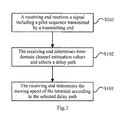
Fig.1 illustrates a schematic flow chart of a method for testing a moving speed of a terminal according to an embodiment of the invention; -
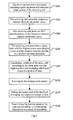
Fig.2 illustrates a schematic flow chart of a particular embodiment of a method for testing a moving speed of a terminal according to an embodiment of the invention; -
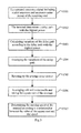
Fig.3 illustrates a schematic flow chart of another particular embodiment of a method for testing a moving speed of a terminal according to an embodiment of the invention; -
Fig.4 illustrates a schematic structural diagram of a device for testing a moving speed of a terminal according to an embodiment of the invention; and -
Fig.5 illustrates another schematic structural diagram of a device for testing a moving speed of a terminal according to an embodiment of the invention. - Embodiments of the invention provide a method for testing a moving speed of a terminal so as to measure the moving speed of the terminal according to pilot and noise power to thereby improve the precision in measurement.
- Referring to
Fig.1 , a method for testing a moving speed of a terminal according to an embodiment of the invention includes: - Operation S101: A receiving end receives a signal including a pilot sequence transmitted by a transmitting end;
- Operation S102: The receiving end determines a time-domain channel estimation value corresponding to each pilot symbol being transmitted, in the pilot sequence, according to a known pilot sequence and the signal including the pilot sequence and selects a delay path according to the time-domain channel estimation values; and
- Operation S103: The receiving end determines the moving speed of the terminal according to the delay path selected in a preset length of time.
- There are typically a number of transmission paths with different delays in transmission over a real space channel, and these different transmission paths are embodied as corresponding power values at different points of time in time-domain channel estimation, where a peak point with a power value above some threshold is referred to as a delay path.
- Preferably the operation S101 furthermore includes: the receiving end determines noise power when the signal including the pilot sequence is received, and a signal to noise ratio corresponding to the noise power; and the operation S102 is performed by the receiving end upon determining that the signal to noise ratio is above a first preset threshold, that is, furthermore the noise power when the signal including the pilot sequence is received and the signal to noise ratio corresponding to the noise power is required to be determined, and it is determined that the signal to noise ratio is above the first preset threshold, before the operation S102.
- Preferably in the operation S102, the receiving end determines a frequency-domain channel estimation value corresponding to each pilot symbol being transmitted, in the pilot sequence, according to the known pilot sequence and the signal including the pilot sequence; and
- The receiving end determines the time-domain channel estimation value corresponding to each pilot symbol according to the frequency-domain channel estimation value corresponding to the pilot symbol.
- Preferably the delay path is selected in the operation S102 as follows:
- The receiving end selects the delay path with the highest power for each pilot symbol; and
- The receiving end determines the location of the selected delay path with the highest power, and if the receiving end determines that locations of delay paths selected for pilot symbols at the same frequency-domain location are different,
- Then the receiving end determines one of the locations of the delay paths and determines the delay path corresponding to the location as the delay path selected for the pilot symbols at the same frequency-domain location, or selects the location of the delay path maximizing the sum of power of the delay paths corresponding to the pilots at the same frequency-domain location and determines the delay path corresponding to the location as the delay path selected for the pilot symbols at the same frequency-domain location.
- Where the location of the delay path refers to a point of time corresponding to the delay path in time-domain channel estimation.
- Preferably the operation S103 includes: the receiving end determines an average variation of the delay path selected in the preset length of time according to the delay path in the preset length of time; and
- The receiving end determines the moving speed of the terminal according to the average variation of the delay path.
- Preferably the receiving end determines the average of the variation of the delay path selected in the preset length of time according to the delay path in the preset length of time as follows:
- The receiving end groups together a plurality of pilot symbols at the same frequency-domain location determined in the preset length of time and calculates variations of the delay path of the pilot symbols spaced by a preset number of Orthogonal Frequency Division Multiplexing (OFDM) symbols in the respective groups;
- The receiving end determines the averages of the variations of the delay path in the respective groups respectively according to the variations of the delay path of the pilot symbols spaced by the preset number of OFDM symbols in the respective groups; and
- The receiving end determines the average variation of the delay path in the preset length of time according to the averages of the variations of the delay path in the respective groups.
- Preferably if the determined moving speed of the terminal is below a second preset threshold, then the receiving end increases the preset number of spacing OFDM symbols and recalculates the average of the variation of the delay path.
- Preferably the receiving end determines the moving speed of the terminal according to the average variation of the delay path as follows:
- The receiving end determines the moving speed of the terminal according to the average variation of the delay path, and a pre-stored relationship between the average variation of the delay path and the moving speed of the terminal.
- Preferably the receiving end determines the noise power when the signal including the pilot sequence is received;
The receiving end determines the average noise power in the preset length of time according to the noise power; and
After the receiving end determines the averages of the variations of the delay path in the respective groups respectively according to the variations of the delay path of the pilot symbols spaced by the preset number of OFDM symbols in the respective groups, the method further includes: - The receiving end revises the average of the variation of the delay path by the average noise power in the preset length of time.
- Preferably the receiving end determines the averages of the variations of the delay path in the respective groups respectively according to the variations of the delay path of the pilot symbols spaced by the preset number of OFDM symbols in the respective groups as follows:
- The receiving end calculates the averages of the variations in the respective groups according to the variations of the delay path in the respective groups;
- The receiving end calculates the squares of the differences between the variations in the respective groups and the averages;
- The receiving end removes the variations with the squares of the differences above a third preset threshold; and
- The receiving end determines the averages of the variations of the delay path in the respective groups respectively by averaging the variations of the delay path remaining after the variations with the squares of the variations above the third preset threshold in the respective groups are removed.
- The invention can also be applicable to a communication system in which a signal including a pilot is transmitted, e.g., a Time Division-Synchronous Code Division Multiple Access (TD-SCDMA), a Long Term Evolution (LTE), a Long Term Evolution-Advanced (LTE-A), etc. Since the data transmitted in the pilot is known, an accurate channel estimation value can be derived directly in the simple Least Square (LS) method, and since the speed is measured before channel estimation is performed on the signal, the current speed measurement result can be applied directly to the current channel estimation and signal detection processes. Several particular embodiments of the invention will be given below.
- In a first particular embodiment, referring to
Fig.2 , in the scenario of an LTE system or an LTE-A system, the transmitting end can be a base station, and the receiving end can be a terminal; or the transmitting end can be a terminal, and the receiving end can be a base station. The moving speed of the terminal can be measured particularly in the following steps: - Operation S201: The receiving end receives a signal including a pilot sequence transmitted by the transmitting end; and
- Also the receiving end obtains and stores noise power Pnoise of the receiving end upon reception of the signal.
- The receiving end determines power of the received signal and determines a corresponding signal to noise ratio according to the power of the received signal and the noise power. Since the precision in measurement may be degraded at a low signal to noise ratio, it can be specified for the signal to noise ratio that the precision in measurement is determined to be satisfactory when the signal to noise ratio is above a first preset threshold, and at this time measurement of the speed can be initiated; otherwise, a default or null value can be applied.
- Operation S202: A received signal r p(i) on Resource Elements (REs) where the pilot sequence is located in the same sub-frame of the signal is taken, where i represents the time-domain index of a pilot, and if the speed is measured according to pilots of the port 0 in a sub-frame of the LTE system, then i = 1,2,3,4, and a frequency-domain channel estimation value H p(i) corresponding to each pilot symbol being transmitted, in the pilot sequence is derived according to a known pilot sequence r seq(i) in the equation of H p(i) = r p(i)/r seq(i).
- Operation S203: A time-domain channel estimation value hi is derived according to the frequency-domain channel estimation value Hp (i) corresponding to each pilot symbol, estimated according to the pilots, particularly by performing Npilot Inverse Fast Fourier Transform (IFFT) on the frequency-domain channel estimation values H p(i) of the respective pilot symbols, where Npilot represents the number of pilots in the frequency-domain, in the equation of:

- Operation S204: A delay path with the highest power (simply referred to as the strongest path) is selected. That is, the strongest path is determined respectively for hi of each pilot symbol, and taking the pilots in the operation S202 as an example, the locations of selected delay paths for h 1, h2, h3 and h 4 are the value of n corresponding to


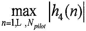

- It is judged whether a preset length of time for which pilot symbols are received expires, and if so, the flow proceeds to the following operations; otherwise, the flow exits for the current sub-frame.
- Operation S205: Variations of the delay path of adjacent pilot symbols in respective sub-frames are obtained by calculating time-domain channel variations according to the stored delay path with the highest power for time-domain channel estimation, taking the downlink LTE system as an example, as follows:
- Since the frequency-domain locations of the first and third columns of pilot symbols are the same, and the frequency-domain locations of the second and fourth columns of pilot symbols are the same, the first and third columns are grouped together, and the second and fourth columns are grouped together, and the variations of the delay path of the adjacent pilot symbols are calculated.
- (δH')2 (1) and (δH')2 (2) are calculated in the equations of:


- The respective groups of (δH')2 (k) of N sub-frames for the statistic operation, calculated in the preset length of time are averaged respectively to get the averages E[(δH')2 (k)] of the respective groups of variations of the delay path.
- In order to make the results more accurate, a smoothing process can be further performed to remove the sub-frames for the statistic operation, with errors above a third threshold and then average the results, particularly as follows: the averages E'[(δH')2 (k)] of the respective variations in the respective groups of (δH')2 (k) are calculated respectively; the squares of the differences δ 1, δ 2, δ3 ......δn between the respective variations in each group of (δH')2 (k) and the average E'[(δH')2 (k)] are calculated; the sub-frames for the statistic operation corresponding to δm(1≤m≤n) above the third threshold are removed; and the variations corresponding to the remaining sub-frames in the respective groups of (δH')2 (k) are averaged again to get the averages E[(δH')2 (k)] of the variations of the delay path in the respective groups.
- Since two columns of pilots at a small spacing are applied at a low speed, so that there is a low difference between their time-domain channel responses, thus resulting in a significant error in measurement. Preferably a threshold is applied to the measurement, and if the value of the measured speed is below a second preset threshold, e.g., 30km/h, then the spacing between each group of pilots for calculation is increased, the statistic operation is performed again, and the measurement result is processed. The following description will be presented taking the LTE downlink system as an example:
- In the original algorithm, pilot symbols at the same frequency-domain are grouped together so that the pilots in the group are spaced by 7 OFDM symbols, and if the measurement result is below the threshold, then a low-speed scenario can be determined, and at this time if pilot symbols spaced by one sub-frame are grouped together, then the pilots in the group are spaced by 14 OFDM symbols, i.e., twice the original spacing, and accordingly the measurement result obtained by referring to a lookup table or the substitution into the equation is also halved.
- Alternatively if pilot symbols spaced by one radio frame are grouped together, then the pilots in the group are spaced by 140 OFDM symbols, i.e., 20 times the original spacing, and accordingly the measurement result obtained by referring to a lookup table or the substitution into the equation is also reduced by a factor of 20, i.e., the real speed.
- Where the method in which the pilot symbols spaced by one sub-frame shall be supported a configuration in which there are two consecutive downlink sub-frames.
- Operation S206: E[(δH')2 (k)] is revised by the average noise power.
- Firstly the noise power values Pnoise at the receiving end in the N sub-frames for the statistic operation are averaged to get the average noise power σ 2, and then the average E[(δH')2 (k)] is revised by the average noise power:

- Operation S207: The obtained respective groups of Δ k are averaged to get the average variation E(Δ k ) of the delay path in the preset length of time, the square root of which is

- Operation S208: ΔH is substituted into the equation of v̂ = F(H) or the "ΔH - V" relationship table is referred to according to ΔH to thereby estimate the current moving speed of the terminal, and in order to improve the precision, a plurality of tables or equations can be stored corresponding to different delay scenarios, and then correspondingly one of the tables or the equations can be selected for the current delay measurement value.
- The relationship between ΔH and the moving speed v in different channel scenarios can be represented in the form of an equation or a table generated by simulating the statistic averages ΔH at different moving speed v, at high signal to noise ratios and in different delay scenarios while the terminal is moving at a constant speed, and creating the fitting equation of v̂ = F(ΔH), or the "ΔH - V " relationship table, in the different delay scenarios according to the statistic averages, and storing the equation or the table into the terminal for which the speed needs to be measured. ΔH can be calculated in the simulation particularly as follows:
- A statistic of the channel variations is made to get the square modulus (δH')2 of the differences in the time-domain channel estimations between the adjacent pilot symbols, where (δH')2 is calculated as in the algorithm to measure the speed; and (δH')2 of M radio frames are averaged, and since the simulation is performed in a scenario with a high signal to noise ratio (>30dB), it will not be necessary to revise the result of the average of (δH')2 by the noise power, but instead the square root thereof can be taken directly as

- With M»N, the value of M shall be large enough to guarantee higher precision of the created equation or table and consequentially the precision in measurement, where it can be judged whether the value of M is sufficiently large by judging whether the statistic result of ΔH is stable as M is further increased (the M is typically on the order of a thousand of frames or more in the LTE system); and the value of N is decided by the acceleration available to the UE and the precision required for the measurement. Typically if the acceleration of the UE is high, then the value of N shall be set small (in the LTE system, if the highest acceleration is 2.8 km/s 2 , then a potentially introduced error in measurement is 10 km/s 2 at N of 100) so that a delay of the measurement value relative to the real value and consequentially the resulting largest error in measurement will not be too large. The larger the value of N is, the higher the precision in measurement will be, while the UE is moving at a constant speed.
- The operations in the embodiment of the invention can be improved and further described as follows:
- (1) The scenario distinguished by the fitting equation of v̂ = F(ΔH) or the "ΔH - V" relationship table is decided by the type of delay distinguished by the algorithm to measure the delay, and if an algorithm to estimate the largest multi-path delay is unavailable to the receiving end, then the simulation needs to be performed by averaging the statistic results of ΔH in the respective delay scenarios and further creating a unique fitting equation of v̂ = F(ΔH) or the "ΔH - V" relationship table common to the respective scenarios.
- (2) A smoothing process can be performed on a number of results of testing the speed for higher precision in measurement.
- (3) When the base station in the LTE system measures the speed upon uplink data, if pilots of a service channel can not be obtained periodically, then it will be feasible to measure the speed using pilots of a Physical Uplink Control Channel (PUCCH) or a Sounding Reference Symbol (SRS).
- In this particular embodiment, since the speed can be measured using the delay path in a simple calculation procedure at a low delay, applicable to scenarios at different delays and different speeds, and the process of testing the speed can be performed before channel estimation is performed on the signal, the result thereof can be applicable directly to the current channel estimation and signal detection processes; and moreover since the result is revised in view of the noise and removing the variations of the delay path with significant mean squared errors, etc., thereby improving the precision in measurement of the speed. The precision of the measurement result can be guaranteed even at a low speed by increasing the spacing between the pilots while performing the calculation.
- In a second particular embodiment, when the moving speed of a terminal in a China Mobile Multimedia Broadcasting (CMMB) system is measured, referring to
Fig.3 , the moving speed of the CMMB terminal is measured using a CMMB downlink broadcast signal particularly in the following operations: - Operation S301: The terminal receives a CMMB broadcast signal including a pilot sequence, where pilot symbols of the CMMB signal are consecutive; and
Also the terminal obtains and stores noise power Pnoise of the receiving end upon reception of the signal. - Operation S302: The terminal derives frequency-domain channel estimation values according to the received pilot symbols and known pilot symbols, derives time-domain channel estimation values hi according to the frequency-domain channel estimation values, and then selects a delay path with the highest power from hi and determines the location ni of the delay path with the highest power for hi , where ni represents the value of n corresponding to

- Moreover firstly noise reduction can be performed on the received signal in the frequency-domain before this operation to thereby improve the precision of data.
- The following operations are performed after a preset length of time for which pilot symbols are received expires:
- Operation S303: The pilot symbols of the CMMB signal are consecutive, including odd pilot symbols at the same frequency-domain location and even pilot symbols at the same frequency-domain locations, so channel estimation is performed on every four symbols grouped together, which are denoted as h 0 , h 1, h 2 and h 3, and results of (δH')2 of the odd and even symbols are calculated respectively as variations of the delay path with the highest power in the equations of:

and
- Operation S304: (δH')2 of the N symbols for the statistic operation are averaged to get E((δH')2 even ) and E((δH')2 odd ).
- Operation S305: (δH')2 is revised by the average noise power.
- Firstly the noise power values Pnoise of the N symbols for the statistic operation are averaged to get the average noise power σ 2, and Δodd and Δeven are calculated as follows:

and
- Operation S306: The odd and even results are averaged to get E[Δ] = (Δeven + Δ odd ) /2, the square root of which is

- Operation S307: "ΔH - V" relationship tables are referred to according to ΔH to thereby estimate the current moving speed of the terminal.
- A signal to noise ratio or channel delay information will not be distinguished in the table, and the number of stored tables can be determined according to the number of levels into which the measured speed is divided, e.g., M levels, where only (M-1) ΔH - V relationship tables need to be stored.
- If the signal to noise ratio is below some threshold, then the lowest measured speed can be determined directly without referring to any relationship table.
- N, M, and the levels of the speed can be selected as required for the precision in measurement. For example, N=100 to 200, M=4, and the levels <30, 30 to 60, 60 to 120 and >120 of the speed can be selected.
- Referring to
Fig.4 , a device for testing a moving speed of a terminal according to an embodiment of the invention includes: - A communicating
module 41 is configured to receive a signal including a pilot sequence transmitted by a transmitting end; - A delay
path determining module 42 is configured to determine a time-domain channel estimation value corresponding to each pilot symbol being transmitted, in the pilot sequence according to a known pilot sequence and the signal including the pilot sequence and to select a delay path according to the time-domain channel estimation values; and - A
speed determining module 43 is configured to determine the moving speed of the terminal according to the delay path selected in a preset length of time. - Preferably the device further includes a first noise determining module configured to determine noise power when the signal including the pilot sequence is received, and to determine a signal to noise ratio corresponding to the noise power according to the noise power.
- The delay
path determining module 42 is configured: - To determine the time-domain channel estimation value corresponding to each pilot symbol being transmitted, in the pilot sequence according to the known pilot sequence and the signal including the pilot sequence, and to select the delay path according to the time-domain channel estimation values, when the first noise determining module determines that the signal to noise ratio is above a first preset threshold.
- Preferably referring to
Fig.5 , the delaypath determining module 42 includes: - A time-domain channel estimation
value determining unit 51 is configured to determine a frequency-domain channel estimation value corresponding to each pilot symbol being transmitted, in the pilot sequence according to the known pilot sequence and the signal including the pilot sequence, and - To determine the time-domain channel estimation value corresponding to the each pilot symbol according to the frequency-domain channel estimation value corresponding to the pilot symbol; and
- A delay path selecting unit 52 is configured to select the delay path according to the time-domain channel estimation values. Preferably the delay path selecting unit 52 is configured:
- To determine the time-domain channel estimation value corresponding to each pilot symbol being transmitted, in the pilot sequence according to the known pilot sequence and the signal including the pilot sequence, and to select the delay path with the highest power according to the time-domain channel estimation values; and
- To determine the location of the selected delay path with the highest power, and if it is determined that locations of delay paths selected for pilot symbols at the same frequency-domain location are different, to select one of the locations of the delay paths and to determine the delay path corresponding to the location as the delay path selected for the pilot symbols at the same frequency-domain location, or to select the location of the delay path maximizing the sum of power of the delay paths corresponding to the pilots at the same frequency-domain location and to determine the delay path corresponding to the location as the delay path selected for the pilot symbols at the same frequency-domain location.
- Preferably referring to
Fig.5 , thespeed determining module 43 includes: - A delay
path calculating unit 53 is configured to determine an average variation of the delay path selected in the preset length of time according to the delay path in the preset length of time; and - A speed calculating unit 54 is configured to determine the moving speed of the terminal according to the average variation of the delay path.
- Preferably the delay
path calculating unit 53 is configured: - To group together a plurality of pilot symbols at the same frequency-domain location determined in the preset length of time and to calculate variations of the delay path of the pilot symbols spaced by a preset number of OFDM symbols in the respective groups;
- To determine the averages of the variations of the delay path in the respective groups respectively according to the variations of the delay path of the pilot symbols spaced by the preset number of OFDM symbols in the respective groups; and
- To determine the average variation of the delay path in the preset length of time according to the averages of the variations of the delay path in the respective groups.
- Preferably the speed calculating unit 54 is configured:
- To determine the moving speed of the terminal according to the average variation of the delay path, and a pre-stored relationship between the average variation of the delay path and the moving speed of the terminal.
- Preferably the delay
path calculating unit 53 is further configured: - If the determined moving speed of the terminal is below a second preset threshold, to increase the preset number;
- To group together a plurality of pilot symbols at the same frequency-domain location determined in the preset length of time and to calculate variations of the delay path of the pilot symbols spaced by the increased preset number of OFDM symbols in the respective groups;
- To determine the averages of the variations of the delay path in the respective groups respectively according to the variations of the delay path of the pilot symbols spaced by the increased preset number of OFDM symbols in the respective groups; and
- To determine the average variation of the delay path in the preset length of time according to the averages of the variations of the delay path in the respective groups.
- Preferably the device further includes:
- A second noise determining module is configured to determine noise power when the signal including the pilot sequence is received, and to determine the average noise power in the preset length of time according to the noise power; and
- After the averages of the variations of the delay path in the respective groups is determined respectively according to the variations of the delay path of the pilot symbols spaced by the preset number of OFDM symbols in the respective groups, the delay
path calculating unit 53 is further configured:- To revise the averages of the variations of the delay path by the average noise power determined by the second noise determining module.
- Preferably the delay
path calculating unit 53 configured to determine the averages of the variations of the delay path in the respective groups respectively according to the variations of the delay path of the pilot symbols spaced by the preset number of OFDM symbols in the respective groups is configured: - To calculate the averages of the variations in the respective groups according to the variations of the delay path in the respective groups;
- To calculate the squares of the differences between the variations in the respective groups and the averages;
- To remove the variations with the squares of the differences above a third preset threshold; and
- To determine the averages of the variations of the delay path in the respective groups respectively by averaging the variations of the delay path remaining after the variations with the squares of the variations above the third preset threshold in the respective groups are removed.
- In summary, in the embodiments of the invention, the receiving end receives a signal including a pilot sequence transmitted by the transmitting end; the receiving end determines a channel response function corresponding to the signal of each pilot sequence being transmitted, according to a pre-stored pilot sequence and the signal including the pilot sequence and determines a corresponding delay path according to the channel response function; and the receiving end determines the moving speed of the terminal according to the delay path. The embodiments of the invention provide a method and device for testing a moving speed of a terminal so as to measure the moving speed of the terminal according to pilots and noise power so as to improve the precision in measurement.
- Those skilled in the art shall appreciate that the embodiments of the invention can be embodied as a method, a system or a computer program product. Therefore the invention can be embodied in the form of an all-hardware embodiment, an all-software embodiment or an embodiment of software and hardware in combination. Furthermore the invention can be embodied in the form of a computer program product embodied in one or more computer useable storage mediums (including but not limited to a disk memory, a CD-ROM, an optical memory, etc.) in which computer useable program codes are contained.
- The invention has been described in a flow chart and/or a block diagram of the method, the device (system) and the computer program product according to the embodiments of the invention. It shall be appreciated that respective flows and/or blocks in the flow chart and/or the block diagram and combinations of the flows and/or the blocks in the flow chart and/or the block diagram can be embodied in computer program instructions. These computer program instructions can be loaded onto a general-purpose computer, a specific-purpose computer, an embedded processor or a processor of another programmable data processing device to produce a machine so that the instructions executed on the computer or the processor of the other programmable data processing device create means for performing the functions specified in the flow(s) of the flow chart and/or the block(s) of the block diagram.
- These computer program instructions can also be stored into a computer readable memory capable of directing the computer or the other programmable data processing device to operate in a specific manner so that the instructions stored in the computer readable memory create an article of manufacture including instruction means which perform the functions specified in the flow(s) of the flow chart and/or the block(s) of the block diagram.
- These computer program instructions can also be loaded onto the computer or the other programmable data processing device so that a series of operational steps are performed on the computer or the other programmable data processing device to create a computer implemented process so that the instructions executed on the computer or the other programmable device provide steps for performing the functions specified in the flow(s) of the flow chart and/or the block(s) of the block diagram.
- Although the preferred embodiments of the invention have been described, those skilled in the art benefiting from the underlying inventive concept can make additional modifications and variations to these embodiments. Therefore the appended claims are intended to be construed as encompassing the preferred embodiments and all the modifications and variations coming into the scope of the invention.
- Evidently those skilled in the art can make various modifications and variations to the invention without departing from the spirit and scope of the invention. Thus the invention is also intended to encompass these modifications and variations thereto so long as the modifications and variations come into the scope of the claims appended to the invention and their equivalents.
Claims (20)
- A method for testing a moving speed of a terminal, wherein the method comprises:receiving, by a receiving end, a signal comprising a pilot sequence transmitted by a transmitting end;determining, by the receiving end, a time-domain channel estimation value corresponding to each pilot symbol being transmitted, in the pilot sequence according to a known pilot sequence and the signal comprising the pilot sequence and selecting a delay path according to the time-domain channel estimation values; anddetermining, by the receiving end, the moving speed of the terminal according to the delay path selected in a preset length of time.
- The method according to claim 1, wherein before determining, by the receiving end, the time-domain channel estimation value corresponding to each pilot symbol being transmitted, in the pilot sequence according to the known pilot sequence and the signal comprising the pilot sequence and selecting the delay path according to the time-domain channel estimation values, the method further comprises:determining, by the receiving end, noise power when the signal comprising the pilot sequence is received, and determining a signal to noise ratio corresponding to the noise power according to the noise power; and determining that the signal to noise ratio is above a first preset threshold.
- The method according to claim 1, wherein determining, by the receiving end, the time-domain channel estimation value corresponding to each pilot symbol being transmitted, in the pilot sequence according to the known pilot sequence and the signal comprising the pilot sequence comprises:determining, by the receiving end, a frequency-domain channel estimation value corresponding to each pilot symbol being transmitted, in the pilot sequence according to the known pilot sequence and the signal comprising the pilot sequence; anddetermining, by the receiving end, the time-domain channel estimation value corresponding to each pilot symbol according to the frequency-domain channel estimation value corresponding to the pilot symbol.
- The method according to claim 1, wherein determining, by the receiving end, the time-domain channel estimation value corresponding to each pilot symbol being transmitted, in the pilot sequence according to the known pilot sequence and the signal comprising the pilot sequence and selecting the delay path according to the time-domain channel estimation values comprises:determining, by the receiving end, the time-domain channel estimation value corresponding to each pilot symbol being transmitted, in the pilot sequence according to the known pilot sequence and the signal comprising the pilot sequence, and selecting a delay path with a highest power according to the time-domain channel estimation values; anddetermining, by the receiving end, a location of the selected delay path with the highest power, and if the receiving end determines that locations of delay paths selected for pilot symbols at the same frequency-domain location are different, then selecting one of the locations of the delay paths and determining the delay path corresponding to the location as the delay path selected for the pilot symbols at the same frequency-domain location, or selecting a location of a delay path maximizing a sum of power of delay paths corresponding to the pilots at the same frequency-domain location and determining the delay path corresponding to the location as the delay path selected for the pilot symbols at the same frequency-domain location.
- The method according to claim 1, wherein determining, by the receiving end, the moving speed of the terminal according to the delay path selected in the preset length of time comprises:determining, by the receiving end, an average variation of the delay path selected in the preset length of time according to the delay path in the preset length of time; anddetermining, by the receiving end, the moving speed of the terminal according to the average variation of the delay path.
- The method according to claim 5, wherein determining, by the receiving end, the average variation of the delay path selected in the preset length of time according to the delay path in the preset length of time comprises:grouping together, by the receiving end, a plurality of pilot symbols at the same frequency-domain location determined in the preset length of time and calculating variations of the delay path of pilot symbols spaced by a preset number of Orthogonal Frequency Division Multiplexing, OFDM, symbols in the respective groups;determining, by the receiving end, averages of the variations of the delay path in the respective groups respectively according to the variations of the delay path of the pilot symbols spaced by the preset number of OFDM symbols in the respective groups; anddetermining, by the receiving end, the average variation of the delay path in the preset length of time according to the averages of the variations of the delay path in the respective groups.
- The method according to claim 5, wherein determining, by the receiving end, the moving speed of the terminal according to the average of the variation of the delay path comprises:determining, by the receiving end, the moving speed of the terminal according to the average variation of the delay path, and a pre-stored relationship between the average variation of the delay path and the moving speed of the terminal.
- The method according to claim 6, wherein the method further comprises:determining, by the receiving end, noise power when the signal comprising the pilot sequence is received, anddetermining, by the receiving end, an average noise power in the preset length of time according to the noise power; andafter the receiving end determines the averages of the variations of the delay path in the respective groups respectively according to the variations of the delay path of the pilot symbols spaced by the preset number of OFDM symbols in the respective groups, the method further comprises:revising, by the receiving end, the averages of the variations of the delay path by the average noise power in the preset length of time.
- The method according to claim 6, wherein the method further comprises:increasing, by the receiving end, the preset number if the determined moving speed of the terminal is below a second preset threshold;grouping together, by the receiving end, a plurality of pilot symbols at the same frequency-domain location determined in the preset length of time and calculating variations of the delay path of the pilot symbols spaced by the increased preset number of OFDM symbols in the respective groups;determining, by the receiving end, the averages of the variations of the delay path in the respective groups respectively according to the variations of the delay path of the pilot symbols spaced by the increased preset number of OFDM symbols in the respective groups; anddetermining, by the receiving end, the average variation of the delay path in the preset length of time according to the averages of the variations of the delay path in the respective groups.
- The method according to claim 6, wherein determining, by the receiving end, the averages of the variations of the delay path in the respective groups respectively according to the variations of the delay path of the pilot symbols spaced by the preset number of OFDM symbols in the respective group comprises:calculating, by the receiving end, the averages of the variations in the respective groups according to the variations of the delay path in the respective groups;calculating, by the receiving end, squares of differences between the variations in the respective groups and the averages;removing, by the receiving end, a variation with a square of difference above a third preset threshold; anddetermining, by the receiving end, the averages of the variations of the delay path in the respective groups respectively by averaging the variations of the delay path remaining after the variation with the square of difference above the third preset threshold in the respective groups is removed.
- A device for testing a moving speed of a terminal, wherein the device comprises:a communicating module configured to receive a signal comprising a pilot sequence transmitted by a transmitting end;a delay path determining module configured to determine a time-domain channel estimation value corresponding to each pilot symbol being transmitted, in the pilot sequence according to a known pilot sequence and the signal comprising the pilot sequence and to select a delay path according to the time-domain channel estimation values; anda speed determining module configured to determine the moving speed of the terminal according to the delay path selected in a preset length of time.
- The device according to claim 11, wherein the device further comprises: a first noise determining module configured to determine noise power when the signal comprising the pilot sequence is received, and to determine a signal to noise ratio corresponding to the noise power according to the noise power; and
the delay path determining module is configured:to determine the time-domain channel estimation value corresponding to each pilot symbol being transmitted, in the pilot sequence according to the known pilot sequence and the signal comprising the pilot sequence, and to select the delay path according to the time-domain channel estimation values, when the first noise determining module determines that the signal to noise ratio is above a first preset threshold. - The device according to claim 11, wherein the delay path determining module comprises:a time-domain channel estimation value determining unit configured to determine a frequency-domain channel estimation value corresponding to each pilot symbol being transmitted, in the pilot sequence according to the known pilot sequence and the signal comprising the pilot sequence; and to determine the time-domain channel estimation value corresponding to each pilot symbol according to the frequency-domain channel estimation value corresponding to the pilot symbol; anda delay path selecting unit configured to select the delay path according to the time-domain channel estimation values.
- The device according to claim 11, wherein the delay path selecting unit is configured:to determine the time-domain channel estimation value corresponding to each pilot symbol being transmitted, in the pilot sequence according to the known pilot sequence and the signal comprising the pilot sequence, and to select a delay path with a highest power according to the time-domain channel estimation values; andto determine a location of the selected delay path with the highest power, and if it is determined that locations of delay paths selected for pilot symbols at the same frequency-domain location are different, to select one of the locations of the delay paths and to determine the delay path corresponding to the location as the delay path selected for the pilot symbols at the same frequency-domain location, orto select a location of a delay path maximizing the sum of power of the delay paths corresponding to the pilots at the same frequency-domain location and to determine the delay path corresponding to the location as the delay path selected for the pilot symbols at the same frequency-domain location.
- The device according to claim 11, wherein the speed determining module comprises:a delay path calculating unit configured to determine an average variation of the delay path selected in the preset length of time according to the delay path in the preset length of time; anda speed calculating unit configured to determine the moving speed of the terminal according to the average variation of the delay path.
- The device according to claim 15, wherein the delay path calculating unit is configured:to group together a plurality of pilot symbols at the same frequency-domain location determined in the preset length of time and to calculate variations of the delay path of the pilot symbols spaced by a preset number of Orthogonal Frequency Division Multiplexing, OFDM, symbols in the respective groups;to determine averages of the variations of the delay path in the respective groups respectively according to the variations of the delay path of the pilot symbols spaced by the preset number of OFDM symbols in the respective groups; andto determine the average variation of the delay path in the preset length of time according to the averages of the variations of the delay path in the respective groups.
- The device according to claim 15, wherein the speed calculating unit is configured:to determine the moving speed of the terminal according to the average variation of the delay path, and a pre-stored relationship between the average variation of the delay path and the moving speed of the terminal.
- The device according to claim 16, wherein the device further comprises:a second noise determining module configured to determine noise power when the signal comprising the pilot sequence is received, and to determine an average noise power in the preset length of time according to the noise power; andafter the averages of the variations of the delay path in the respective groups is determined respectively according to the variations of the delay path of the pilot symbols spaced by the preset number of OFDM symbols in the respective groups, the delay path calculating unit is further configured:to revise the averages of the variations of the delay path by the average noise power determined by the second noise determining module.
- The device according to claim 16, wherein the delay path calculating unit is further configured:if the determined moving speed of the terminal is below a second preset threshold, to increase the preset number;to group together a plurality of pilot symbols at the same frequency-domain location determined in the preset length of time and to calculate variations of the delay path of the pilot symbols spaced by the increased preset number of OFDM symbols in the respective groups;to determine the averages of the variations of the delay path in the respective groups respectively according to the variations of the delay path of the pilot symbols spaced by the increased preset number of OFDM symbols in the respective groups; andto determine the average variation of the delay path in the preset length of time according to the averages of the variations of the delay path in the respective groups.
- The device according to claim 16, wherein the delay path calculating unit configured to determine the averages of the variations of the delay path in the respective groups respectively according to the variations of the delay path of the pilot symbols spaced by the preset number of OFDM symbols in the respective groups is configured:to calculate the averages of the variations in the respective groups according to the variations of the delay path in the respective groups;to calculate squares of differences between the variations in the respective groups and the averages;to remove a variation with a square of difference above a third preset threshold; andto determine the averages of the variations of the delay path in the respective groups respectively by averaging the variations of the delay path remaining after the variation with the square of difference above the third preset threshold in the respective groups is removed.
Applications Claiming Priority (2)
| Application Number | Priority Date | Filing Date | Title |
|---|---|---|---|
| CN201210365083.5A CN103686830A (en) | 2012-09-26 | 2012-09-26 | Method and device for measuring movement speed of terminal |
| PCT/CN2013/078394 WO2014048150A1 (en) | 2012-09-26 | 2013-06-28 | Method and device for testing moving speed of terminal |
Publications (3)
| Publication Number | Publication Date |
|---|---|
| EP2905986A1 true EP2905986A1 (en) | 2015-08-12 |
| EP2905986A4 EP2905986A4 (en) | 2015-11-18 |
| EP2905986B1 EP2905986B1 (en) | 2017-11-08 |
Family
ID=50322817
Family Applications (1)
| Application Number | Title | Priority Date | Filing Date |
|---|---|---|---|
| EP13842167.2A Active EP2905986B1 (en) | 2012-09-26 | 2013-06-28 | Method and device for testing moving speed of terminal |
Country Status (5)
| Country | Link |
|---|---|
| US (1) | US9271259B2 (en) |
| EP (1) | EP2905986B1 (en) |
| CN (1) | CN103686830A (en) |
| TW (1) | TWI493210B (en) |
| WO (1) | WO2014048150A1 (en) |
Families Citing this family (8)
| Publication number | Priority date | Publication date | Assignee | Title |
|---|---|---|---|---|
| CN105992241B (en) * | 2015-02-27 | 2019-08-06 | 电信科学技术研究院 | A kind of estimation method and device of moving velocity of terminal |
| CN106877985B (en) * | 2015-12-11 | 2020-10-13 | 皓创科技(镇江)有限公司 | Method for processing pilot symbols and node equipment |
| CN105848198B (en) * | 2016-03-18 | 2019-07-02 | 京信通信系统(中国)有限公司 | A method and device for determining terminal speed |
| US10045346B1 (en) * | 2016-08-02 | 2018-08-07 | Sprint Spectrum L.P. | Assigning a low-GDV carrier to a high-speed UE |
| US10912046B2 (en) * | 2016-09-29 | 2021-02-02 | Sharp Kabushiki Kaisha | Terminal apparatus, base station apparatus, communication method, and integrated circuit |
| CN108574955B (en) * | 2017-03-07 | 2023-04-14 | 中兴通讯股份有限公司 | Method and device for measurement optimization in UE-triggered mobility scenarios |
| EP3573385B1 (en) * | 2017-03-09 | 2023-07-12 | Huawei Technologies Co., Ltd. | Wireless communication method, control device, node, and terminal device |
| CN114337968B (en) * | 2021-12-28 | 2023-06-06 | 湖南智领通信科技有限公司 | Active pilot frequency adjusting method and device based on real-time measurement and control data |
Family Cites Families (15)
| Publication number | Priority date | Publication date | Assignee | Title |
|---|---|---|---|---|
| CN1245843C (en) * | 2002-12-12 | 2006-03-15 | 华为技术有限公司 | Device and method for estimating speed in wireless communication system |
| DE60334904D1 (en) * | 2003-09-05 | 2010-12-23 | St Microelectronics Srl | Doppler spread method in mobile radio communication systems |
| KR101002857B1 (en) * | 2003-09-16 | 2010-12-21 | 삼성전자주식회사 | Method and device for estimating speed of mobile terminal in mobile communication system |
| JP4592358B2 (en) * | 2004-08-31 | 2010-12-01 | 株式会社エヌ・ティ・ティ・ドコモ | Mobile communication system and mobile communication method |
| CN101057468B (en) * | 2004-11-15 | 2014-06-18 | 皇家飞利浦电子股份有限公司 | Method and device for detecting high-mobility state of mobile terminal and related equipment |
| US8619884B2 (en) * | 2005-09-02 | 2013-12-31 | Qualcomm Incorporated | Communication channel estimation |
| CN101437243B (en) * | 2007-11-16 | 2010-09-29 | 大唐移动通信设备有限公司 | Method and apparatus for measuring motion velocity of mobile station |
| RU2471298C2 (en) * | 2008-03-14 | 2012-12-27 | Квэлкомм Инкорпорейтед | Methods and systems to select cyclic delays in ofdm systems with multiple antennas |
| JP4774435B2 (en) * | 2008-11-21 | 2011-09-14 | 株式会社半導体理工学研究センター | Doppler frequency estimation device, receiving device, program, and Doppler frequency estimation method |
| CN101557378B (en) * | 2009-05-18 | 2011-12-28 | 普天信息技术研究院有限公司 | Method for pilot transmitting, channel estimation and noise power estimation in OFDM system |
| US8379706B2 (en) * | 2009-07-28 | 2013-02-19 | Qualcomm Incorporated | Signal and noise power estimation |
| CN102487364B (en) * | 2010-12-02 | 2015-02-04 | 无锡物联网产业研究院 | Channel estimation method and apparatus thereof |
| CN102325101B (en) * | 2011-07-08 | 2013-12-11 | 电信科学技术研究院 | Method and device for measuring speed by using pilot frequency |
| CN102281170B (en) * | 2011-08-08 | 2014-11-05 | 电信科学技术研究院 | Speed measuring method and device based on channel estimation |
| CN104105984B (en) * | 2011-11-04 | 2017-04-12 | Zte维创通讯公司 | Method and apparatus for estimating speed of a mobile terminal |
-
2012
- 2012-09-26 CN CN201210365083.5A patent/CN103686830A/en active Pending
-
2013
- 2013-06-28 WO PCT/CN2013/078394 patent/WO2014048150A1/en not_active Ceased
- 2013-06-28 US US14/428,984 patent/US9271259B2/en active Active
- 2013-06-28 EP EP13842167.2A patent/EP2905986B1/en active Active
- 2013-09-18 TW TW102133783A patent/TWI493210B/en active
Also Published As
| Publication number | Publication date |
|---|---|
| TW201413276A (en) | 2014-04-01 |
| CN103686830A (en) | 2014-03-26 |
| WO2014048150A1 (en) | 2014-04-03 |
| US9271259B2 (en) | 2016-02-23 |
| TWI493210B (en) | 2015-07-21 |
| EP2905986B1 (en) | 2017-11-08 |
| EP2905986A4 (en) | 2015-11-18 |
| US20150223194A1 (en) | 2015-08-06 |
Similar Documents
| Publication | Publication Date | Title |
|---|---|---|
| EP2905986B1 (en) | Method and device for testing moving speed of terminal | |
| CN105391671B (en) | Method and apparatus for channel estimation and equalization | |
| EP1924040A2 (en) | Channel estimation device | |
| CN102647387B (en) | The removing method of co-channel interference and device | |
| EP3258615B1 (en) | Antenna calibration method and apparatus | |
| US8755464B2 (en) | Method and apparatus for performing channel estimation in a wireless communication system | |
| EP3993332A1 (en) | Method and apparatus for determining doppler shift | |
| US20120269084A1 (en) | Radio base station | |
| CN112714086B (en) | Frequency offset estimation method and base station | |
| US20130065581A1 (en) | Mobile telecommunication system with noise ratio estimation mechanism and method of operation thereof | |
| CN102325101A (en) | Method and device for measuring speed by using pilot frequency | |
| CN102201879A (en) | Measurement method and device for interference noise of long term evolution (LTE) system | |
| EP2924936A1 (en) | Channel estimation method and device | |
| CN102238114B (en) | Method and device for determining valid signal-to-noise ratio | |
| CN101437243A (en) | Method and apparatus for measuring motion velocity of mobile station | |
| US10686637B2 (en) | Receiving apparatus and receiving method | |
| EP2947786B1 (en) | Method and apparatus for configuring transmission mode | |
| CN102857962A (en) | Method and device for speed measurement and based on information channel estimation | |
| US9397780B2 (en) | Receiving device and receiving method, and computer program | |
| EP3565199B1 (en) | Channel estimation method and device | |
| US20110261870A1 (en) | Apparatus and method for measuring radio quality | |
| US9413563B2 (en) | Method and apparatus for channel estimation using localized SINR in wireless communication systems | |
| CN103457901B (en) | Mixed carrier method for transmitting signals based on channel-aware | |
| KR102792891B1 (en) | Techniques for Estimation of Cyclic Shift in OFDM-based Communication System | |
| CN105187353A (en) | Symbol timing synchronization method and device in OFDM system |
Legal Events
| Date | Code | Title | Description |
|---|---|---|---|
| PUAI | Public reference made under article 153(3) epc to a published international application that has entered the european phase |
Free format text: ORIGINAL CODE: 0009012 |
|
| 17P | Request for examination filed |
Effective date: 20150423 |
|
| AK | Designated contracting states |
Kind code of ref document: A1 Designated state(s): AL AT BE BG CH CY CZ DE DK EE ES FI FR GB GR HR HU IE IS IT LI LT LU LV MC MK MT NL NO PL PT RO RS SE SI SK SM TR |
|
| AX | Request for extension of the european patent |
Extension state: BA ME |
|
| RA4 | Supplementary search report drawn up and despatched (corrected) |
Effective date: 20151021 |
|
| RIC1 | Information provided on ipc code assigned before grant |
Ipc: G01S 11/06 20060101ALI20151015BHEP Ipc: H04W 24/08 20090101AFI20151015BHEP Ipc: H04W 64/00 20090101ALI20151015BHEP Ipc: H04L 27/26 20060101ALI20151015BHEP |
|
| DAX | Request for extension of the european patent (deleted) | ||
| RIC1 | Information provided on ipc code assigned before grant |
Ipc: G01S 11/06 20060101ALI20160909BHEP Ipc: H04L 27/26 20060101ALI20160909BHEP Ipc: H04W 64/00 20090101ALI20160909BHEP Ipc: H04W 24/08 20090101AFI20160909BHEP |
|
| 17Q | First examination report despatched |
Effective date: 20160921 |
|
| STAA | Information on the status of an ep patent application or granted ep patent |
Free format text: STATUS: EXAMINATION IS IN PROGRESS |
|
| GRAP | Despatch of communication of intention to grant a patent |
Free format text: ORIGINAL CODE: EPIDOSNIGR1 |
|
| STAA | Information on the status of an ep patent application or granted ep patent |
Free format text: STATUS: GRANT OF PATENT IS INTENDED |
|
| INTG | Intention to grant announced |
Effective date: 20170607 |
|
| GRAS | Grant fee paid |
Free format text: ORIGINAL CODE: EPIDOSNIGR3 |
|
| GRAA | (expected) grant |
Free format text: ORIGINAL CODE: 0009210 |
|
| STAA | Information on the status of an ep patent application or granted ep patent |
Free format text: STATUS: THE PATENT HAS BEEN GRANTED |
|
| AK | Designated contracting states |
Kind code of ref document: B1 Designated state(s): AL AT BE BG CH CY CZ DE DK EE ES FI FR GB GR HR HU IE IS IT LI LT LU LV MC MK MT NL NO PL PT RO RS SE SI SK SM TR |
|
| REG | Reference to a national code |
Ref country code: GB Ref legal event code: FG4D |
|
| REG | Reference to a national code |
Ref country code: AT Ref legal event code: REF Ref document number: 945252 Country of ref document: AT Kind code of ref document: T Effective date: 20171115 Ref country code: CH Ref legal event code: EP |
|
| REG | Reference to a national code |
Ref country code: IE Ref legal event code: FG4D |
|
| REG | Reference to a national code |
Ref country code: DE Ref legal event code: R096 Ref document number: 602013029278 Country of ref document: DE |
|
| REG | Reference to a national code |
Ref country code: NL Ref legal event code: MP Effective date: 20171108 |
|
| REG | Reference to a national code |
Ref country code: LT Ref legal event code: MG4D |
|
| REG | Reference to a national code |
Ref country code: AT Ref legal event code: MK05 Ref document number: 945252 Country of ref document: AT Kind code of ref document: T Effective date: 20171108 |
|
| PG25 | Lapsed in a contracting state [announced via postgrant information from national office to epo] |
Ref country code: ES Free format text: LAPSE BECAUSE OF FAILURE TO SUBMIT A TRANSLATION OF THE DESCRIPTION OR TO PAY THE FEE WITHIN THE PRESCRIBED TIME-LIMIT Effective date: 20171108 Ref country code: NO Free format text: LAPSE BECAUSE OF FAILURE TO SUBMIT A TRANSLATION OF THE DESCRIPTION OR TO PAY THE FEE WITHIN THE PRESCRIBED TIME-LIMIT Effective date: 20180208 Ref country code: FI Free format text: LAPSE BECAUSE OF FAILURE TO SUBMIT A TRANSLATION OF THE DESCRIPTION OR TO PAY THE FEE WITHIN THE PRESCRIBED TIME-LIMIT Effective date: 20171108 Ref country code: LT Free format text: LAPSE BECAUSE OF FAILURE TO SUBMIT A TRANSLATION OF THE DESCRIPTION OR TO PAY THE FEE WITHIN THE PRESCRIBED TIME-LIMIT Effective date: 20171108 Ref country code: NL Free format text: LAPSE BECAUSE OF FAILURE TO SUBMIT A TRANSLATION OF THE DESCRIPTION OR TO PAY THE FEE WITHIN THE PRESCRIBED TIME-LIMIT Effective date: 20171108 Ref country code: SE Free format text: LAPSE BECAUSE OF FAILURE TO SUBMIT A TRANSLATION OF THE DESCRIPTION OR TO PAY THE FEE WITHIN THE PRESCRIBED TIME-LIMIT Effective date: 20171108 |
|
| PG25 | Lapsed in a contracting state [announced via postgrant information from national office to epo] |
Ref country code: IS Free format text: LAPSE BECAUSE OF FAILURE TO SUBMIT A TRANSLATION OF THE DESCRIPTION OR TO PAY THE FEE WITHIN THE PRESCRIBED TIME-LIMIT Effective date: 20180308 Ref country code: LV Free format text: LAPSE BECAUSE OF FAILURE TO SUBMIT A TRANSLATION OF THE DESCRIPTION OR TO PAY THE FEE WITHIN THE PRESCRIBED TIME-LIMIT Effective date: 20171108 Ref country code: HR Free format text: LAPSE BECAUSE OF FAILURE TO SUBMIT A TRANSLATION OF THE DESCRIPTION OR TO PAY THE FEE WITHIN THE PRESCRIBED TIME-LIMIT Effective date: 20171108 Ref country code: GR Free format text: LAPSE BECAUSE OF FAILURE TO SUBMIT A TRANSLATION OF THE DESCRIPTION OR TO PAY THE FEE WITHIN THE PRESCRIBED TIME-LIMIT Effective date: 20180209 Ref country code: BG Free format text: LAPSE BECAUSE OF FAILURE TO SUBMIT A TRANSLATION OF THE DESCRIPTION OR TO PAY THE FEE WITHIN THE PRESCRIBED TIME-LIMIT Effective date: 20180208 Ref country code: RS Free format text: LAPSE BECAUSE OF FAILURE TO SUBMIT A TRANSLATION OF THE DESCRIPTION OR TO PAY THE FEE WITHIN THE PRESCRIBED TIME-LIMIT Effective date: 20171108 Ref country code: AT Free format text: LAPSE BECAUSE OF FAILURE TO SUBMIT A TRANSLATION OF THE DESCRIPTION OR TO PAY THE FEE WITHIN THE PRESCRIBED TIME-LIMIT Effective date: 20171108 |
|
| REG | Reference to a national code |
Ref country code: FR Ref legal event code: PLFP Year of fee payment: 6 |
|
| PG25 | Lapsed in a contracting state [announced via postgrant information from national office to epo] |
Ref country code: DK Free format text: LAPSE BECAUSE OF FAILURE TO SUBMIT A TRANSLATION OF THE DESCRIPTION OR TO PAY THE FEE WITHIN THE PRESCRIBED TIME-LIMIT Effective date: 20171108 Ref country code: CY Free format text: LAPSE BECAUSE OF FAILURE TO SUBMIT A TRANSLATION OF THE DESCRIPTION OR TO PAY THE FEE WITHIN THE PRESCRIBED TIME-LIMIT Effective date: 20171108 Ref country code: EE Free format text: LAPSE BECAUSE OF FAILURE TO SUBMIT A TRANSLATION OF THE DESCRIPTION OR TO PAY THE FEE WITHIN THE PRESCRIBED TIME-LIMIT Effective date: 20171108 Ref country code: SK Free format text: LAPSE BECAUSE OF FAILURE TO SUBMIT A TRANSLATION OF THE DESCRIPTION OR TO PAY THE FEE WITHIN THE PRESCRIBED TIME-LIMIT Effective date: 20171108 Ref country code: CZ Free format text: LAPSE BECAUSE OF FAILURE TO SUBMIT A TRANSLATION OF THE DESCRIPTION OR TO PAY THE FEE WITHIN THE PRESCRIBED TIME-LIMIT Effective date: 20171108 |
|
| REG | Reference to a national code |
Ref country code: DE Ref legal event code: R097 Ref document number: 602013029278 Country of ref document: DE |
|
| PG25 | Lapsed in a contracting state [announced via postgrant information from national office to epo] |
Ref country code: IT Free format text: LAPSE BECAUSE OF FAILURE TO SUBMIT A TRANSLATION OF THE DESCRIPTION OR TO PAY THE FEE WITHIN THE PRESCRIBED TIME-LIMIT Effective date: 20171108 Ref country code: SM Free format text: LAPSE BECAUSE OF FAILURE TO SUBMIT A TRANSLATION OF THE DESCRIPTION OR TO PAY THE FEE WITHIN THE PRESCRIBED TIME-LIMIT Effective date: 20171108 Ref country code: PL Free format text: LAPSE BECAUSE OF FAILURE TO SUBMIT A TRANSLATION OF THE DESCRIPTION OR TO PAY THE FEE WITHIN THE PRESCRIBED TIME-LIMIT Effective date: 20171108 Ref country code: RO Free format text: LAPSE BECAUSE OF FAILURE TO SUBMIT A TRANSLATION OF THE DESCRIPTION OR TO PAY THE FEE WITHIN THE PRESCRIBED TIME-LIMIT Effective date: 20171108 |
|
| PLBE | No opposition filed within time limit |
Free format text: ORIGINAL CODE: 0009261 |
|
| STAA | Information on the status of an ep patent application or granted ep patent |
Free format text: STATUS: NO OPPOSITION FILED WITHIN TIME LIMIT |
|
| 26N | No opposition filed |
Effective date: 20180809 |
|
| PG25 | Lapsed in a contracting state [announced via postgrant information from national office to epo] |
Ref country code: SI Free format text: LAPSE BECAUSE OF FAILURE TO SUBMIT A TRANSLATION OF THE DESCRIPTION OR TO PAY THE FEE WITHIN THE PRESCRIBED TIME-LIMIT Effective date: 20171108 |
|
| REG | Reference to a national code |
Ref country code: CH Ref legal event code: PL |
|
| REG | Reference to a national code |
Ref country code: BE Ref legal event code: MM Effective date: 20180630 |
|
| PG25 | Lapsed in a contracting state [announced via postgrant information from national office to epo] |
Ref country code: LU Free format text: LAPSE BECAUSE OF NON-PAYMENT OF DUE FEES Effective date: 20180628 Ref country code: MC Free format text: LAPSE BECAUSE OF FAILURE TO SUBMIT A TRANSLATION OF THE DESCRIPTION OR TO PAY THE FEE WITHIN THE PRESCRIBED TIME-LIMIT Effective date: 20171108 |
|
| REG | Reference to a national code |
Ref country code: IE Ref legal event code: MM4A |
|
| PG25 | Lapsed in a contracting state [announced via postgrant information from national office to epo] |
Ref country code: LI Free format text: LAPSE BECAUSE OF NON-PAYMENT OF DUE FEES Effective date: 20180630 Ref country code: CH Free format text: LAPSE BECAUSE OF NON-PAYMENT OF DUE FEES Effective date: 20180630 Ref country code: IE Free format text: LAPSE BECAUSE OF NON-PAYMENT OF DUE FEES Effective date: 20180628 |
|
| PG25 | Lapsed in a contracting state [announced via postgrant information from national office to epo] |
Ref country code: BE Free format text: LAPSE BECAUSE OF NON-PAYMENT OF DUE FEES Effective date: 20180630 |
|
| PG25 | Lapsed in a contracting state [announced via postgrant information from national office to epo] |
Ref country code: MT Free format text: LAPSE BECAUSE OF NON-PAYMENT OF DUE FEES Effective date: 20180628 |
|
| PG25 | Lapsed in a contracting state [announced via postgrant information from national office to epo] |
Ref country code: TR Free format text: LAPSE BECAUSE OF FAILURE TO SUBMIT A TRANSLATION OF THE DESCRIPTION OR TO PAY THE FEE WITHIN THE PRESCRIBED TIME-LIMIT Effective date: 20171108 |
|
| PG25 | Lapsed in a contracting state [announced via postgrant information from national office to epo] |
Ref country code: PT Free format text: LAPSE BECAUSE OF FAILURE TO SUBMIT A TRANSLATION OF THE DESCRIPTION OR TO PAY THE FEE WITHIN THE PRESCRIBED TIME-LIMIT Effective date: 20171108 |
|
| PG25 | Lapsed in a contracting state [announced via postgrant information from national office to epo] |
Ref country code: HU Free format text: LAPSE BECAUSE OF FAILURE TO SUBMIT A TRANSLATION OF THE DESCRIPTION OR TO PAY THE FEE WITHIN THE PRESCRIBED TIME-LIMIT; INVALID AB INITIO Effective date: 20130628 Ref country code: MK Free format text: LAPSE BECAUSE OF NON-PAYMENT OF DUE FEES Effective date: 20171108 |
|
| PG25 | Lapsed in a contracting state [announced via postgrant information from national office to epo] |
Ref country code: AL Free format text: LAPSE BECAUSE OF FAILURE TO SUBMIT A TRANSLATION OF THE DESCRIPTION OR TO PAY THE FEE WITHIN THE PRESCRIBED TIME-LIMIT Effective date: 20171108 |
|
| REG | Reference to a national code |
Ref country code: DE Ref legal event code: R081 Ref document number: 602013029278 Country of ref document: DE Owner name: DATANG MOBILE COMMUNICATIONS EQUIPMENT CO., LT, CN Free format text: FORMER OWNER: CHINA ACADEMY OF TELECOMMUNICATIONS TECHNOLOGY, BEIJING, CN |
|
| REG | Reference to a national code |
Ref country code: GB Ref legal event code: 732E Free format text: REGISTERED BETWEEN 20211007 AND 20211013 |
|
| PGFP | Annual fee paid to national office [announced via postgrant information from national office to epo] |
Ref country code: DE Payment date: 20250618 Year of fee payment: 13 |
|
| PGFP | Annual fee paid to national office [announced via postgrant information from national office to epo] |
Ref country code: GB Payment date: 20250618 Year of fee payment: 13 |
|
| PGFP | Annual fee paid to national office [announced via postgrant information from national office to epo] |
Ref country code: FR Payment date: 20250625 Year of fee payment: 13 |