EP2905959A1 - Dispositif d'affichage autostéréoscopique - Google Patents
Dispositif d'affichage autostéréoscopique Download PDFInfo
- Publication number
- EP2905959A1 EP2905959A1 EP14183376.4A EP14183376A EP2905959A1 EP 2905959 A1 EP2905959 A1 EP 2905959A1 EP 14183376 A EP14183376 A EP 14183376A EP 2905959 A1 EP2905959 A1 EP 2905959A1
- Authority
- EP
- European Patent Office
- Prior art keywords
- sub
- pixel
- display
- light output
- pixels
- Prior art date
- Legal status (The legal status is an assumption and is not a legal conclusion. Google has not performed a legal analysis and makes no representation as to the accuracy of the status listed.)
- Withdrawn
Links
Images


Classifications
-
- H—ELECTRICITY
- H04—ELECTRIC COMMUNICATION TECHNIQUE
- H04N—PICTORIAL COMMUNICATION, e.g. TELEVISION
- H04N13/00—Stereoscopic video systems; Multi-view video systems; Details thereof
- H04N13/30—Image reproducers
- H04N13/302—Image reproducers for viewing without the aid of special glasses, i.e. using autostereoscopic displays
- H04N13/317—Image reproducers for viewing without the aid of special glasses, i.e. using autostereoscopic displays using slanted parallax optics
-
- H—ELECTRICITY
- H04—ELECTRIC COMMUNICATION TECHNIQUE
- H04N—PICTORIAL COMMUNICATION, e.g. TELEVISION
- H04N13/00—Stereoscopic video systems; Multi-view video systems; Details thereof
- H04N13/30—Image reproducers
- H04N13/302—Image reproducers for viewing without the aid of special glasses, i.e. using autostereoscopic displays
- H04N13/305—Image reproducers for viewing without the aid of special glasses, i.e. using autostereoscopic displays using lenticular lenses, e.g. arrangements of cylindrical lenses
-
- H—ELECTRICITY
- H04—ELECTRIC COMMUNICATION TECHNIQUE
- H04N—PICTORIAL COMMUNICATION, e.g. TELEVISION
- H04N2213/00—Details of stereoscopic systems
- H04N2213/001—Constructional or mechanical details
Definitions
- This invention relates to an autostereoscopic display device which comprises a display panel having an array of display pixels, and an arrangement for directing different views to different physical locations.
- a sub-pixel with a single sub-area is referred to as monolithic.
- a sub-pixel may have multiple sub-areas.
- a known autostereoscopic display device comprises a two-dimensional liquid crystal display panel having a row and column array of display pixels acting as an image forming means to produce a display.
- An array of elongated lenses extending parallel to one another overlies the display pixel array and acts as a view forming means. These are known as "lenticular lenses”. Outputs from the display pixels are projected through these lenticular lenses, which function to modify the directions of the outputs.
- the lenticular lenses are provided as a sheet of lens elements, each of which comprises an elongate semi-cylindrical lens element.
- the lenticular lenses extend in the column direction of the display panel, with each lenticular lens overlying a respective group of two or more adjacent columns of display sub-pixels.
- Each lenticular lens can be associated with two columns of display sub-pixels to enable a user to observe a single stereoscopic image. Instead, each lenticular lens can be associated with a group of three or more adjacent display sub-pixels in the row direction. Corresponding columns of display sub-pixels in each group are arranged appropriately to provide a vertical slice from a respective two dimensional sub-image. As a user's head is moved from left to right a series of successive, different, stereoscopic views are observed creating, for example, a look-around impression.
- the above described autostereoscopic display device produces a display having good levels of brightness.
- one problem associated with the device is that the views projected by the lenticular sheet are separated by dark zones caused by "imaging" of the non-emitting black matrix which typically defines the display sub-pixel array. These dark zones are readily observed by a user as brightness non-uniformities in the form of dark vertical bands spaced across the display. The bands move across the display as the user moves from left to right and the pitch of the bands changes as the user moves towards or away from the display.
- each pixel is divided into 3 sub-pixels, transmitting or emitting red (R), green (G) and blue (B) light, respectively.
- Sub-pixels of equal color are typically arranged in columns. This is the structure of the most standard RGB panel, with so-called RGB-stripes.
- Each sub-pixel is surrounded by the black matrix. It is the regularity of the pixel grid (and color distribution) combined with the magnification of the lenticular lens which causes the banding problem.
- Another problem is that vertically aligned lenses result in a reduction in resolution in the horizontal direction only, while the resolution in the vertical direction is not altered.
- Another approach for reducing the amplitude of the non-uniformities is the so-called fractional view arrangement, which is described in detail in WO 2006/117707 A2 .
- Devices having a fractional view arrangement are characterised in that the pitch of the slanted lenticular lenses is not equal to an integer number times the pitch of the (smallest) display pixels (i.e. the sub-pixel pitch in a color display), and in that the pixels under successive lenticular lenses are positioned in a horizontally alternating fashion.
- the successive lenses simultaneously project different amounts of the black matrix, leading to intensity modulations which are mutually shifted in phase.
- the first harmonic of the total intensity cancels out, leaving a much less intense non-uniformity effect.
- the intensity modulation depth introduced by imaging the black matrix may be reduced significantly. Rendering of the views is, however, more complicated and therefore more computationally intensive.
- Another important aspect is a relationship between the display sub-pixel sizes and shapes and the way the 2D sub-pixels are mapped to sub-pixels of the 3D images.
- Some display panels now include multiple addressed areas per sub-pixel. These enable part of the modulation of the pixel brightness at the display panel itself, by enabling different areas of the sub-pixels to be addressed. This can for example give an increased number of different brightness levels and better control of low brightness values. This also enables increased use of black and white areas instead of mid-level greys, which can give improved LCD uniformity over oblique angles.
- an autostereoscopic display device comprising:
- Each position within a sub-pixel light output area is directly beneath a corresponding part of the elongate element.
- the relative position (in the width direction) between that position within the sub-pixel light output area and the elongate element determines the direction in which the generated light is output.
- the intensity profile is the integration over all of the light output area of the sub-pixel for each relative width position. In this way it shows the spread of light output directions resulting from the sub-pixel light output area.
- close together in the width direction is meant closer together than would be the case for sub-pixel light output areas which are not offset from the column direction.
- the invention thus relates to a display in which each sub-pixel is divided into different areas (but they are addressed with the same image data).
- the sub-pixel light output areas generate a light intensity profile across the elongate element width direction.
- This intensity profile is that different positions along the width direction of the elongate elements translate to different view directions.
- the intensity profiles are brought closer together (in terms of the width direction position) as explained above. This means that the sub-pixel light output areas are positioned so that they are mapped to closer together view output directions. This avoids spreading of the combined intensity profile of the overall sub-pixel.
- the intensity profile is preferably symmetric about a centre line, when projected from the elongate element width direction to the row direction.
- the significance of projecting the intensity profile to the row direction is that this is the way the view moves, i.e. from left to right or right to left. In this way, the transition between views is the same when a viewer moves left to right or right to left.
- each sub-pixel light output area is generally directed (i.e. the centre line of its intensity profile is directed) to the same view direction.
- each sub-pixel light output area has a centre of area, wherein the centres of area are aligned along a line parallel to the elongate elements. This is an example of how to achieve the intensity profiles aligned at the same width position of the elongate elements.
- Each pixel may comprise at least three sub-pixels having different colors, e.g. a red, green and blue sub-pixel, arranged in the row direction. In this way, the display can be based on a standard RGB pixel layout.
- Each sub-pixel light output area may have the same shape, and each may produce a light intensity profile across the width direction in the form of a rectangle, a triangle, a top hat or a raised cosine function.
- the sub-pixel light output areas may include at least two different shapes.
- Each sub-pixel light output area may be shaped individually to eliminate banding, and the slanted positioning of the areas then avoids the introduction of cross talk. Banding is avoided by making the intensity profile (when projected to the row/horizontal direction) decrease from its peak to the half intensity, and increase from zero to the half intensity, with same function. In this way, where adjacent intensity profiles overlap, the combined intensity viewed from any particular viewing angle is constant (assuming the display is providing a uniform output from all sub-pixels).
- the view forming arrangement may comprise lenticular lenses.
- the tangent of the slant angle may for example be 1/9, or 1/6, or 1/3.
- the device may comprise a switchable 2D/3D display, wherein the view forming arrangement is switchable.
- the invention is of particular interest for switchable displays as it enables a conventional or near convention configuration of the display panel for optimum operation in the 2D mode, and also allows low banding and low crosstalk operation in the 3D mode.
- the view forming arrangement may for example comprise lenticular lenses formed using a switchable liquid crystal material.
- a method for producing an autostereoscopic display output comprising:
- the invention provides an autostereoscopic display device with a particular design of display panel.
- the display has an array of display pixels arranged in orthogonal rows and columns of color sub-pixels.
- a view forming arrangement is for projecting a plurality of views towards a user in different directions, and it comprises elongate elements which extend at an acute slant angle to the column direction of the color sub-pixels.
- Each sub-pixel comprises a plurality of individually addressable sub-pixel light output areas stacked generally in the column direction.
- Each sub-pixel light output area has a corresponding output intensity profile along the width direction of an associated elongate element.
- the intensity profiles are at the same width direction position with respect to a closest portion of the associated elongate element.
- the different areas are thus projected to the same view and banding as well as cross talk can be reduced.
- Fig. 1 is a schematic perspective view of a known multi-view autostereoscopic display device 1.
- the known device 1 comprises a liquid crystal display panel 3 of the active matrix type that acts as an image forming means to produce the display.
- the device can instead use OLED pixels.
- the display panel 3 has an orthogonal array of display sub-pixels 5 arranged in rows and columns. For the sake of clarity, only a small number of display sub-pixels 5 are shown in Fig. 1 . In practice, the display panel 3 might comprise about one thousand rows and several thousand columns of display sub-pixels 5.
- the structure of the liquid crystal display panel 3 is entirely conventional.
- the panel 3 comprises a pair of spaced transparent glass substrates, between which an aligned twisted nematic or other liquid crystal material is provided.
- the substrates carry patterns of transparent indium tin oxide (ITO) electrodes on their facing surfaces.
- Polarising layers are also provided on the outer surfaces of the substrates.
- Each display sub-pixel 5 comprises opposing electrodes on the substrates, with the intervening liquid crystal material therebetween.
- the shape and layout of the display sub-pixels 5 are determined by the shape and layout of the electrodes and a black matrix arrangement provided on the front of the panel 3.
- the display sub-pixels 5 are regularly spaced from one another by gaps.
- Each display sub-pixel 5 is associated with a switching element, such as a thin film transistor (TFT) or thin film diode (TFD).
- TFT thin film transistor
- TFD thin film diode
- the display sub-pixels are operated to produce the display by providing addressing signals to the switching elements, and suitable addressing schemes will be known to those skilled in the art.
- the display panel 3 is illuminated by a light source 7 comprising, in this case, a planar backlight extending over the area of the display pixel array. Light from the light source 7 is directed through the display panel 3, with the individual display sub-pixels 5 being driven to modulate the light and produce the display.
- a light source 7 comprising, in this case, a planar backlight extending over the area of the display pixel array. Light from the light source 7 is directed through the display panel 3, with the individual display sub-pixels 5 being driven to modulate the light and produce the display.
- the display device 1 also comprises a lenticular sheet 9, arranged over the display side of the display panel 3, which performs a view forming function.
- the lenticular sheet 9 comprises a row of lenticular lenses 11 extending parallel to one another, of which only one is shown with exaggerated dimensions for the sake of clarity.
- the lenticular lenses 11 act as view forming elements to perform a view forming function.
- the lenticular lenses 11 are in the form of convex (semi-) cylindrical elements, and they act as a light output directing means to provide different images, or views, from the display panel 3 to the eyes of a user positioned in front of the display device 1.
- the autostereoscopic display device 1 shown in Fig. 1 is capable of providing several different perspective views in different directions.
- each lenticular lens 11 overlies a small group of display sub-pixels 5 in each row.
- the lenticular element 11 projects each display sub-pixel 5 of a group in a different direction, so as to form the several different views.
- the user's head moves from left to right, his/her eyes will receive different ones of the several views, in turn.
- Fig. 2 shows the principle of operation of a lenticular type imaging arrangement as described above and shows the light source 7, display panel 3 and the lenticular sheet 9.
- the arrangement provides three views each projected in different directions.
- Each sub-pixel of the display panel 3 is driven with information for one specific view.
- the above described autostereoscopic display device produces a display having good levels of brightness.
- a problem associated with the device is that the views projected by the lenticular sheet 9 are separated by dark zones caused by imaging of the non-emitting black matrix which defines the display pixel array. These dark zones are readily observed by a user as brightness non-uniformities in the form of dark vertical bands spaced across the display.
- the bands move across the display as the user moves from left to right and the pitch of the bands changes as the user moves towards or away from the display.
- the bands are particularly problematic in devices having a high proportion of their display area as black matrix, such as high resolution displays designed for mobile applications.
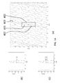
- Fig. 3A shows generalised plots of brightness intensity against viewing angle for the display device shown in Figs. 1 and 2 .
- the way these intensity profiles can be defined is explained further below with reference to Fig. 11 .
- the upper plot shows the contributions of the individual views, which contributions each have constant brightness intensity, interposed between the dark bands caused by imaging of the black matrix, which bands each have zero brightness intensity.
- the transition between views and dark bands is a step transition.
- the lower plot shows the cumulative effect of the contributions of the individual views, that is to say the brightness levels observed by the user moving across the front of the display. It can be seen from the lower plot that there is a significant modulation of the brightness intensity.
- the amplitude of the non-uniformities can be reduced by the well known technique of slanting the lenticular lenses 11 at an acute angle relative to the column direction of the display pixel array.
- the resulting brightness non-uniformities are illustrated in Fig. 3B .
- the upper plot again shows the contributions of the individual views interposed between the dark bands caused by imaging of the black matrix. It can be seen that the transition between views and dark bands is gradual, with the brightness intensity changing at a constant rate.
- the lower plot shows the cumulative effect of the contributions of the individual views, and it can be seen that the intensity modulation depth introduced by imaging the black matrix is significantly reduced. However, it remains difficult to reduce this intensity modulation depth to below 1%, at which level the non-uniformities remain perceivable and distracting for a user.
- the technique of slanting the lenticular lenses 11 may serve to reduce the perceived brightness non-uniformities caused by imaging of the black matrix, further significant reductions can advantageously be achieved by defocusing the lenticular lenses 11.
- the focal lengths of the lenticular lenses 11 are extended so that their focal points lie behind the plane of the display panel 3.
- the resulting brightness non-uniformities are illustrated in Fig. 3C .
- the transition between views and dark bands is gradual, with intensity changing at a varying rate.
- the lower plot shows the cumulative effect of the contributions of the individual views, and it can be seen that the intensity modulation depth introduced by imaging the black matrix is almost completely eliminated.
- Fig. 4 shows the native sub-pixel layout of the 2D display panel as well as, on the same scale, the sub-pixel layout in a 3D view obtained by putting a lenticular in front of the panel.
- the sub-pixel layout shown for the 3D image represents the sub-pixel pattern as seen from one viewing direction.
- the same geometric sub-pixel pattern is seen from all viewing directions, but different sets of sub-pixels of the underlying 2D display are visible.
- a blue 3D sub-pixel is an image of one or more blue sub-pixels of the native 2D display (and the same applies for green and red).
- p x p y .
- the lens pitch is thus 7.5 when expressed as a number of sub-pixel dimensions in the row direction.
- This lens pitch can be defined by a value p in the horizontal direction, in units of the horizontal sub-pixel pitch ⁇ x.
- the 3D image has a repeating pattern of sub-pixels, and the colors of a few sub-pixels (R, G and B) are shown so that all colors in the pattern can be understood.
- Each color is output as a diamond shaped grid of sub-pixels which are interleaved with each other.
- each 3D sub-pixel has contributions from three 2D sub-pixels (each 3D sub-pixel is divided into three sections). This is because a line parallel to the lenticular lens axis (such as the lines shown over the 2D display panel) cross three sub-pixels of one color, followed by three sub-pixels of the next color, followed by three sub-pixels of the last color. For different viewing angle directions, there can instead be two full sub-pixels for each 3D sub-pixel.
- the slant angle of the lenticular as well as its pitch should be chosen such that a number of requirements are fulfilled as much as possible:
- the sub-pixels of each color should be distributed in a pattern that is regular and having a resolution that is similar for the horizontal and vertical direction. As shown in Fig. 4 , the horizontal distance between neighbouring green sub-pixels (A to A' in Fig. 3 ) should be comparable to the vertical distance between neighbouring green sub-pixels (B to B'). This should hold for the other colors as well.
- the combination of a lenticular in front of a display panel is very susceptible to the occurrence of moire, which is the banding problem discussed above caused by the combination of the periodicity of the sub-pixel and black mask layout of the display panel and the periodicity of the lenticular.
- Fig. 5 shows a conventional RGB striped pixel layout. Each pixel has three sub-pixels, hence the subscript "3" in RGB_3. Pixel layouts using more than 3 primary colors are also known, and these are termed "multi-primary" pixel layouts. Several such multi-primary layouts have reached the market and are expected to become mainstream,
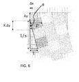
- Fig. 6 is an enlarged view of one 3D pixel from Fig. 4 . Note that the slant can be in either direction with respect to the column direction.
- the value K shown in Fig. 5 is the ratio of the height (in the column direction) of a 3D sub-pixel to the height of a 2D sub-pixel.
- the value K represents how many 2D sub-pixels contribute to each 3D sub-pixel.
- K is not necessarily an integer value
- Fig. 6 shows a value of K slightly greater than 1.
- one 2D sub-pixel should contribute to each 3D sub-pixel. Therefore the slant should to be close to the aspect ratio, as can be seen in Eq. 2.
- small values of slant are preferred.
- the preferred slant should be equal to or smaller than 1/3.
- the distribution of horizontal and vertical resolution should be approximately equal in the 3D mode.
- the pitch i.e. the width of the lenticular lenses, expressed as the number of display sub-pixels which fit into the lens width
- the pitch can be chosen close to the value of 1 / a.
- non-integer pitch values will allow a reduction in banding even further.
- integral pitch values p there are only p possible positions of the lens in relation to any sub-pixel on a row. When looking from an optimal position then some sub-pixels are fully visible while others are fully invisible. When shifting the panel with respect to the lens, or when looking at the display from a different angle, then all sub-pixels are at most partially visible. Clearly there are more and less preferred angles.
- a fractional pitch value addresses this problem my making all angles have a similar quality (hence also reducing banding).
- Display sub-pixels having different relative position with respect to an individual lenticular lens contribute to the views in different angular directions.
- Both the sub-pixel layout and lenticular lens layout has a periodicity, and the number of views (also known as the phases or cone positions) is the minimum number of subpixels which are positioned differently with respect to the periodic lenticular lens.
- the lens array is randomly positioned over the display panel, there are many different possible relative positions and consequently the spatial pattern of view numbers (also known as lens phases or cone positions) is generally irregular.
- N p ⁇ lcm den p , den z , where den( ⁇ ) is for denominator of a fraction and 1cm( ⁇ , ⁇ ) is the lowest common denominator of two arguments.
- the number of fractional views N is the number of unique relative positions of a sub-pixel under the lens. The above formula computes this number and is based on how quickly the pattern repeats in column and row direction.
- One approach is to start with an initial sub-pixel shape and compute an intensity profile by integrating along the optical axes of the lens array.
- the profile should be flat, but when the computed profile is not, the profile can be corrected by manipulating the shape or transmission characteristics of the sub-pixels. This may for example be achieved using a filter mask, for example using the techniques disclosed in WO2007/054851 .
- the sub-pixels should be shaped such that the width at half-height (w) of the intensity profile corresponds to kp / N for positive integer k, and lenticular pitch p measured along the horizontal direction.
- the first of these defines a left-right symmetry along the x axis (which defines the position with respect to the lenticular width, and therefore the view direction). This means the transition between views is the same from left to right as from right to left.
- the second defines an up-down symmetry along the intensity (f(x)) axis about the half intensity value.
- the effect of this is that the sum of two overlapping intensity profiles is always f(0).
- the intensity of one profile decreases, the intensity of an overlapping profile increases to maintain a constant combined intensity. This gives a banding free transition between views.
- suitable shapes for the intensity profile include the rectangle, triangle, flat top triangle and raised cosine functions.
- Fig. 7 shows the corresponding intensity functions with the rectangle shown in Fig. 7(a) , the triangle shown in Fig. 7(b) , the flat top triangle shown in Fig. 7(c) and the raised cosine shown in Fig. 7(d) .
- w 1
- w the width of the intensity profile at half height, as explained above.
- the y-axis plots the intensity "I" in arbitrary units ("a.u.”), normalised to a maximum value of 1.
- Fig. 10 shows that the increased width gives zero banding, but the intensity profile is twice as wide giving less view separation and more spatial resolution
- Spatial resolution relates to how many sub-pixels are visible from each view point. When the intensity profiles are broader, the sub-pixels are more often visible and hence the spatial resolution is higher.
- the first method is more useful for adapting an existing design while the second approach is appropriate for a design-from scratch approach.
- the second approach means it is possible to design a virtually zero-crosstalk 3D lenticular display by creating a rectangular sub-pixel intensity profile and ensuring a good focus (i.e. narrow point spread function).
- This approach can be used for dual-view systems (stereo) and for multi-view systems with large 3D effect. It avoids the need for a defocus function as discussed above.
- the disadvantage of the rectangular profile is that a viewer moving in respect to the display "clicks" through the views, suddenly switching perspective with each such click. It would require a lot of views to reduce the size of the clicks and generate smooth motion parallax (i.e. a look around effect) with a rectangular profile. Having a smoother profile such as a triangle or preferably a function that resembles a raised cosine gives some crosstalk but makes the experience more realistic.
- Modern TV panels have sub-pixels with multiple active areas with different gamma curves.
- the different areas can be driven independently but there is only one drive value per sub-pixel to control all of the areas.
- a light output value can be built up using progressively more areas. This means that better control of lower brightness values can be achieved, and a greater number of overall brightness levels can be defined.
- banding has to be cancelled for each set of areas separately. If not, then a display might suffer from banding in low-, medium- or high light output regions of operation.
- the invention is of particular interest for 2D/3D switchable lenticular displays based on the common RGB-striped layout, and where sub-pixels comprise multiple (two or more) sub-pixel light output areas.
- This pixel layout may be desired for the 2D mode.
- the invention provides an adaptation to improve the operation in the 3D mode without adversely affecting the desired operation in the 2D mode.
- Fig. 11(a) shows a sub-pixel 100 which is formed of two sub-pixel light output areas 101,102.
- Fig. 11(b) shows how the intensity profiles 105 and 106 of the sub-pixel light output areas 101 and 102 of the sub-pixel 100 (across the row direction 104) can be determined by integration along the lens slant direction 103.
- the intensity profiles 105,106 are based on the length of the sub-pixel light output area 101,102 at the particular position beneath the lenticular lens. This is shown in Fig. 11 . Note that for a non-uniform intensity over area, the light intensity profile will need to take into account the the different intensities at different positions of the sub-pixel light output area.
- each sub-pixel light output area 101,102 has a corresponding output intensity profile along the width direction of the associated lens (or more generally the width direction of the elongate view forming element).
- associated is meant the lens which is over that sub-pixel.
- Each intensity profile is symmetric about a centre line once projected into the row direction (which is the direction moved by the viewer). It should be understood that to form the "intensity profile along the width direction" as used herein, all light contributions in the perpendicular direction (in the elongate element long axis direction) are summed, i.e. integrated, to arrive at the light intensity for that particular width position.
- the claims and description should be understood accordingly.
- the intensity profile across the lenses is projected to the row direction to arrive at a profile which represents the way the intensity varies for a viewer moving left to right. This is the intensity profile which has left-right reflective symmetry as well as the banding free functionality.
- the percentage values show the brightness level applied to the sub-pixel light output area 101.
- 100% is the maximum brightness for the single sub-pixel light output area 101, for example corresponding to a 50% overall brightness level for the full sub-pixel.
- both sub-pixel light output areas 101,102 are used.
- the first sub-pixel light output area 101 modulates the light output
- the second sub-pixel light output area is used to modulate the light output. This gives the brightness-dependent shape and position shown in Fig. 11(d) .
- the percentage values show the brightness level applied to overall sub-pixel.
- Overall brightness level 25% is achieved by driving the sub-pixel light output area 101 to 50% (and it can be seen that the shape corresponds to that in Fig. 11(c) ).
- Overall brightness level 50% is achieved by driving the sub-pixel light output area 101 to 100% (and it can be seen that the shape corresponds to that in Fig. 11(c) ).
- both sub-pixel light output areas are used.
- the first sub-pixel light output area 101 can be driven to 50% of its full brightness (contributing the first 25% of the overall sub-pixel brightness) and the second sub-pixel light output area 102 can be driven to 100% brightness (contributing the last 50% of the overall brightness).
- the second sub-pixel light output area 102 can be driven to 100% brightness (contributing the last 50% of the overall brightness).
- full brightness both sub-pixel light output areas are fully driven.
- a problem with this is that the width-wise position centre of the intensity profile of the overall sub-pixel depends on the brightness level of the sub-pixel.
- the view directing function of the lenticular lens causes this change in position to translate to a change in the direction of the emanating beam.
- the shape and width of the intensity profile of a sub-pixel also depends on the brightness level of the sub-pixel. This corresponds to the width of the emanating beam changing.
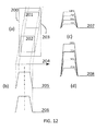
- Fig. 12 shows a first example of pixel layout for an autostereoscopic display.
- Fig. 12(a) shows the native display with multiple active areas 201,202 per sub-pixel 200. The example shown has two such areas and they are both rectangles.
- each intensity profile 205,206 is at the same width direction position with respect to a closest portion of the associated lenticular (i.e. the part of the associated lenticular lens which is over the light output area and therefore controlling the direction in which the light is displayed).
- each sub-pixel light output area 201,202 has a centre of area, and the centres of area are aligned parallel to the slant direction 203 of the lenticular lenses.
- the areas forming the sub-pixel are shifted such that the centres of their respective intensity profiles 205,206 are closer as viewed along the slant direction, and preferably aligned.
- Fig. 12(b) shows the intensity profiles 205 and 206 of the sub-pixel light output areas 201 and 202 of the sub-pixel 200, again determined by integration along the lens slant direction 203.
- Fig. 12(c) shows the combined sub-pixel output for low brightness levels where only sub-pixel light output area 201 modulates the light output
- Fig. 12(d) shows the combined sub-pixel output for higher brightness levels when both areas are used.
- the percentages in Fig. 12 represent the same drive conditions as in Fig. 11 .
- the percentages in Fig. 12(c) and Fig. 13(c) are the drive levels for a single sub-pixel light output area
- the percentages in Fig. 12(d) and Fig. 13(d) are for the overall sub-pixel output brightness.
- Fig. 12 shows full alignment of the sub-pixel light output areas within the sub-pixel in the lens slant direction, and this prevents brightness-dependent view number or crosstalk.
- Fig. 13 shows a second example of pixel layout for an autostereoscopic display.
- Fig. 13(a) shows the native display with multiple active areas 301,302 per sub-pixel 300.
- the example shown has one rectangular sub-pixel light output area 301 and one triangular sub-pixel light output area 302.
- the centre of the respective intensity profiles (as measured along the width direction) are again slanted in the same way as the lenticular slant direction 303.
- the areas forming the sub-pixel are shifted such that the centres of their respective intensity profiles 305,306 are closer as viewed along the lens width direction, and preferably aligned.
- Fig. 13(b) shows the intensity profiles 305 and 306 of the sub-pixel light output areas 301 and 302 of the sub-pixel 300 when projected to the horizontal row direction.
- Fig. 13(c) shows the combined sub-pixel output for low brightness levels where only rectangular area 301 modulates the light output, and
- Fig. 13(d) shows the combined sub-pixel output for higher brightness levels when both areas are used.
- a brightness-dependent view and crosstalk filter can be used as part of the pixel signal processing.
- the sub-pixel light output areas typically have a uniform output intensity over area. However, if the intensity varies over area, this can be taken into account when calculating the intensity profiles that will result.
- a first approach is for a zero-banding, zero-crosstalk multi-view 3D lenticular display, with discrete (clicking) views.
- the areas in the sub-pixel are aligned to the slant direction to reduce or eliminate the shift intensity profile.
- This example is essentially as shown in Fig. 12 .
- a second approach is for a zero-banding, low-crosstalk (smooth) multi-view 3D lenticular display.
- N 3 + 6m for positive integer m.
- Smoother profiles are used, such as the intensity profile of Fig. 7(d) and the parameters p, N and w are chosen to achieve an acceptable balance between spatial and angular resolution.
- Fig. 14 shows an example of this approach.
- the pixel arrangement is shown in Fig. 14(a) , with sub-pixels 400 which comprise two areas 401,402, with their centres aligned along the lenticular axis direction 403.
- Fig. 14(b) shows the intensity profile for an individual area and Fig. 14(c) shows the intensity profile for the overall sub-pixel.
- a third approach is for a high-aperture, zero-banding (smooth and bright) multi-view 3D lenticular display.
- N » p it is advantageous to have N » p, without making the design too irregular, because it allows to choose the intensity width w close to 1 to improve the sub-pixel aperture.
- the higher aperture reduces the view separation but the pitch can be enlarged to compensate.
- the pixel arrangement is shown in Fig. 15(a) , with sub-pixels 500 which comprise two sub-pixel light output areas 501,502, with their centres aligned along the lenticular axis direction 503.
- Fig. 15(b) shows the intensity profile for an individual area and
- Fig. 15(c) shows the intensity profile for the overall sub-pixel.
- Fig. 16(a) the pixel arrangement is shown in Fig. 16(a) , with sub-pixels 600 which comprise two sub-pixel light output areas 601,602, with their centres aligned along the lenticular axis direction 603.
- Fig. 16(b) shows the intensity profile for an individual sub-pixel light output area
- Fig. 16(c) shows the intensity profile for the overall sub-pixel.
- the barrier opening can be considered to be the "view forming element". Furthermore, it is the relative slant between sub-pixel columns and the lenticular (or barrier) axis which is important. Thus, lenticulars or barriers can be provided over the sub-pixel grid as described above.
- the invention is of interest for non-switchable or switchable autostereoscopic displays.
- autostereoscopic 3D displays provide excellent viewing experience for 3D video and pictures, a good 2D performance - as is required especially for viewing text - is obtainable only in displays where the autostereoscopic viewing arrangement is made switchable from the 2D to 3D mode.
- full parallax autostereoscopic 3D displays based on microlenses.
- the lenticular elements of the switchable device operate in a "pass through" mode, i.e. they act in much the same way as would a flat sheet of optically transparent material.
- the resulting display has a high resolution, equal to the native resolution of the display panel, which is suitable for the display of small text characters from short viewing distances.
- the two-dimensional display mode cannot, of course, provide a stereoscopic image.
- the lenticular elements of the switchable device provide a light output directing function.
- the resulting display is capable of providing stereoscopic images, but also suffers the inevitable resolution loss mentioned above.
- the lenticular elements of the switchable device use an electro-optic material, such as a liquid crystal material, having a refractive index that is switchable between two different values for polarized light.
- the device is then switched between the modes by applying an appropriate electrical potential to electrode layers provided above and below the lenticular elements.
- the electrical potential alters the refractive index of the lenticular elements in relation to that of an adjacent optically transparent layer.
- the adjacent optically transparent layer may be formed of the electro-optic material, with the same result that the refractive index of the lenticular elements in relation to the optically transparent layer is altered.
- the sub-pixel light output areas may be positioned along a slanted line which has a smaller slant angle than the lenticular slant.
- a reduction in width of the overall intensity profile can still be achieved and a reduction in view direction dependency on brightness levels, by bringing the view directions closer than for vertically stacked sub-pixel light output areas.
- the available space and desired pixel aperture will determine how much slant is desired in the sub-pixel light output areas.
- the invention has been defined in terms of the light intensity profiles.
- the invention may alternatively be defined in terms of the sub-pixel light output area shapes and positions.
- the invention provides (claim 14):
Priority Applications (1)
| Application Number | Priority Date | Filing Date | Title |
|---|---|---|---|
| EP14183376.4A EP2905959A1 (fr) | 2014-09-03 | 2014-09-03 | Dispositif d'affichage autostéréoscopique |
Applications Claiming Priority (1)
| Application Number | Priority Date | Filing Date | Title |
|---|---|---|---|
| EP14183376.4A EP2905959A1 (fr) | 2014-09-03 | 2014-09-03 | Dispositif d'affichage autostéréoscopique |
Publications (1)
| Publication Number | Publication Date |
|---|---|
| EP2905959A1 true EP2905959A1 (fr) | 2015-08-12 |
Family
ID=51518543
Family Applications (1)
| Application Number | Title | Priority Date | Filing Date |
|---|---|---|---|
| EP14183376.4A Withdrawn EP2905959A1 (fr) | 2014-09-03 | 2014-09-03 | Dispositif d'affichage autostéréoscopique |
Country Status (1)
| Country | Link |
|---|---|
| EP (1) | EP2905959A1 (fr) |
Citations (5)
| Publication number | Priority date | Publication date | Assignee | Title |
|---|---|---|---|---|
| US6064424A (en) | 1996-02-23 | 2000-05-16 | U.S. Philips Corporation | Autostereoscopic display apparatus |
| US6069650A (en) | 1996-11-14 | 2000-05-30 | U.S. Philips Corporation | Autostereoscopic display apparatus |
| WO2006117707A2 (fr) | 2005-04-29 | 2006-11-09 | Koninklijke Philips Electronics N.V. | Appareil d'affichage stereoscopique |
| WO2007054851A1 (fr) | 2005-11-09 | 2007-05-18 | Koninklijke Philips Electronics N.V. | Dispositif d'affichage avec un filtre d'atténuation homogénéisant |
| WO2012169466A1 (fr) * | 2011-06-10 | 2012-12-13 | シャープ株式会社 | Dispositif d'affichage |
-
2014
- 2014-09-03 EP EP14183376.4A patent/EP2905959A1/fr not_active Withdrawn
Patent Citations (5)
| Publication number | Priority date | Publication date | Assignee | Title |
|---|---|---|---|---|
| US6064424A (en) | 1996-02-23 | 2000-05-16 | U.S. Philips Corporation | Autostereoscopic display apparatus |
| US6069650A (en) | 1996-11-14 | 2000-05-30 | U.S. Philips Corporation | Autostereoscopic display apparatus |
| WO2006117707A2 (fr) | 2005-04-29 | 2006-11-09 | Koninklijke Philips Electronics N.V. | Appareil d'affichage stereoscopique |
| WO2007054851A1 (fr) | 2005-11-09 | 2007-05-18 | Koninklijke Philips Electronics N.V. | Dispositif d'affichage avec un filtre d'atténuation homogénéisant |
| WO2012169466A1 (fr) * | 2011-06-10 | 2012-12-13 | シャープ株式会社 | Dispositif d'affichage |
Similar Documents
| Publication | Publication Date | Title |
|---|---|---|
| US10298916B2 (en) | Autostereoscopic image output device | |
| US10750163B2 (en) | Autostereoscopic display device and display method | |
| TWI451162B (zh) | 自動立體影像顯示裝置 | |
| JP6099696B2 (ja) | 自動立体視表示装置 | |
| JP5899389B1 (ja) | オートステレオスコピックディスプレイ装置 | |
| KR100880819B1 (ko) | 자동입체 표시장치의 픽셀 배열 | |
| US9436014B2 (en) | Autostereoscopic display apparatus having optical magnification | |
| US20120092763A1 (en) | Autostereoscopic display apparatus and method | |
| US9313480B2 (en) | Display device in which multiple images are displayed using four neighboring pixels, display panel and electronic apparatus using same | |
| KR20120018370A (ko) | 무안경 입체식 디스플레이 디바이스 | |
| US9807375B2 (en) | Three dimensional image display device | |
| EP2380046A1 (fr) | Dispositif d'affichage autostéréoscopique | |
| KR102261218B1 (ko) | 스트라이프 백라이트와 두 렌티큘러 렌즈 배열들을 갖는 무안경 입체영상 디스플레이 장치 | |
| JP2012104375A (ja) | 表示装置およびバックライト装置 | |
| EP2905959A1 (fr) | Dispositif d'affichage autostéréoscopique | |
| WO2014173853A1 (fr) | Dispositif d'affichage autostéréoscopique à feuille lenticulaire inclinée par rapport à la colonne de sous-pixels colorés |
Legal Events
| Date | Code | Title | Description |
|---|---|---|---|
| PUAI | Public reference made under article 153(3) epc to a published international application that has entered the european phase |
Free format text: ORIGINAL CODE: 0009012 |
|
| AK | Designated contracting states |
Kind code of ref document: A1 Designated state(s): AL AT BE BG CH CY CZ DE DK EE ES FI FR GB GR HR HU IE IS IT LI LT LU LV MC MK MT NL NO PL PT RO RS SE SI SK SM TR |
|
| AX | Request for extension of the european patent |
Extension state: BA ME |
|
| STAA | Information on the status of an ep patent application or granted ep patent |
Free format text: STATUS: THE APPLICATION HAS BEEN WITHDRAWN |
|
| 18W | Application withdrawn |
Effective date: 20151117 |