EP2905858A1 - Over-voltage prevention device - Google Patents
Over-voltage prevention device Download PDFInfo
- Publication number
- EP2905858A1 EP2905858A1 EP15153940.0A EP15153940A EP2905858A1 EP 2905858 A1 EP2905858 A1 EP 2905858A1 EP 15153940 A EP15153940 A EP 15153940A EP 2905858 A1 EP2905858 A1 EP 2905858A1
- Authority
- EP
- European Patent Office
- Prior art keywords
- short
- circuit device
- over
- circuit
- voltage
- Prior art date
- Legal status (The legal status is an assumption and is not a legal conclusion. Google has not performed a legal analysis and makes no representation as to the accuracy of the status listed.)
- Granted
Links
Images



Classifications
-
- H—ELECTRICITY
- H02—GENERATION; CONVERSION OR DISTRIBUTION OF ELECTRIC POWER
- H02H—EMERGENCY PROTECTIVE CIRCUIT ARRANGEMENTS
- H02H7/00—Emergency protective circuit arrangements specially adapted for specific types of electric machines or apparatus or for sectionalised protection of cable or line systems, and effecting automatic switching in the event of an undesired change from normal working conditions
- H02H7/08—Emergency protective circuit arrangements specially adapted for specific types of electric machines or apparatus or for sectionalised protection of cable or line systems, and effecting automatic switching in the event of an undesired change from normal working conditions for dynamo-electric motors
- H02H7/09—Emergency protective circuit arrangements specially adapted for specific types of electric machines or apparatus or for sectionalised protection of cable or line systems, and effecting automatic switching in the event of an undesired change from normal working conditions for dynamo-electric motors against over-voltage; against reduction of voltage; against phase interruption
-
- H—ELECTRICITY
- H02—GENERATION; CONVERSION OR DISTRIBUTION OF ELECTRIC POWER
- H02H—EMERGENCY PROTECTIVE CIRCUIT ARRANGEMENTS
- H02H7/00—Emergency protective circuit arrangements specially adapted for specific types of electric machines or apparatus or for sectionalised protection of cable or line systems, and effecting automatic switching in the event of an undesired change from normal working conditions
- H02H7/06—Emergency protective circuit arrangements specially adapted for specific types of electric machines or apparatus or for sectionalised protection of cable or line systems, and effecting automatic switching in the event of an undesired change from normal working conditions for dynamo-electric generators; for synchronous capacitors
- H02H7/065—Emergency protective circuit arrangements specially adapted for specific types of electric machines or apparatus or for sectionalised protection of cable or line systems, and effecting automatic switching in the event of an undesired change from normal working conditions for dynamo-electric generators; for synchronous capacitors against excitation faults
-
- H—ELECTRICITY
- H02—GENERATION; CONVERSION OR DISTRIBUTION OF ELECTRIC POWER
- H02H—EMERGENCY PROTECTIVE CIRCUIT ARRANGEMENTS
- H02H7/00—Emergency protective circuit arrangements specially adapted for specific types of electric machines or apparatus or for sectionalised protection of cable or line systems, and effecting automatic switching in the event of an undesired change from normal working conditions
- H02H7/10—Emergency protective circuit arrangements specially adapted for specific types of electric machines or apparatus or for sectionalised protection of cable or line systems, and effecting automatic switching in the event of an undesired change from normal working conditions for converters; for rectifiers
-
- H—ELECTRICITY
- H02—GENERATION; CONVERSION OR DISTRIBUTION OF ELECTRIC POWER
- H02H—EMERGENCY PROTECTIVE CIRCUIT ARRANGEMENTS
- H02H9/00—Emergency protective circuit arrangements for limiting excess current or voltage without disconnection
- H02H9/04—Emergency protective circuit arrangements for limiting excess current or voltage without disconnection responsive to excess voltage
- H02H9/041—Emergency protective circuit arrangements for limiting excess current or voltage without disconnection responsive to excess voltage using a short-circuiting device
-
- H—ELECTRICITY
- H02—GENERATION; CONVERSION OR DISTRIBUTION OF ELECTRIC POWER
- H02J—ELECTRIC POWER NETWORKS; CIRCUIT ARRANGEMENTS OR SYSTEMS FOR SUPPLYING OR DISTRIBUTING ELECTRIC POWER; SYSTEMS FOR STORING ELECTRIC ENERGY
- H02J3/00—Circuit arrangements for AC mains or AC distribution networks
- H02J3/38—Arrangements for feeding a single network from two or more generators or sources in parallel; Arrangements for feeding already energised networks from additional generators or sources in parallel
- H02J3/381—Dispersed generators
-
- H—ELECTRICITY
- H02—GENERATION; CONVERSION OR DISTRIBUTION OF ELECTRIC POWER
- H02P—CONTROL OR REGULATION OF ELECTRIC MOTORS, ELECTRIC GENERATORS OR DYNAMO-ELECTRIC CONVERTERS; CONTROLLING TRANSFORMERS, REACTORS OR CHOKE COILS
- H02P29/00—Arrangements for regulating or controlling electric motors, appropriate for both AC and DC motors
- H02P29/02—Providing protection against overload without automatic interruption of supply
- H02P29/024—Detecting a fault condition, e.g. short circuit, locked rotor, open circuit or loss of load
- H02P29/0241—Detecting a fault condition, e.g. short circuit, locked rotor, open circuit or loss of load the fault being an overvoltage
-
- H—ELECTRICITY
- H02—GENERATION; CONVERSION OR DISTRIBUTION OF ELECTRIC POWER
- H02J—ELECTRIC POWER NETWORKS; CIRCUIT ARRANGEMENTS OR SYSTEMS FOR SUPPLYING OR DISTRIBUTING ELECTRIC POWER; SYSTEMS FOR STORING ELECTRIC ENERGY
- H02J2101/00—Supply or distribution of decentralised, dispersed or local electric power generation
- H02J2101/20—Dispersed power generation using renewable energy sources
- H02J2101/28—Wind energy
-
- Y—GENERAL TAGGING OF NEW TECHNOLOGICAL DEVELOPMENTS; GENERAL TAGGING OF CROSS-SECTIONAL TECHNOLOGIES SPANNING OVER SEVERAL SECTIONS OF THE IPC; TECHNICAL SUBJECTS COVERED BY FORMER USPC CROSS-REFERENCE ART COLLECTIONS [XRACs] AND DIGESTS
- Y02—TECHNOLOGIES OR APPLICATIONS FOR MITIGATION OR ADAPTATION AGAINST CLIMATE CHANGE
- Y02E—REDUCTION OF GREENHOUSE GAS [GHG] EMISSIONS, RELATED TO ENERGY GENERATION, TRANSMISSION OR DISTRIBUTION
- Y02E10/00—Energy generation through renewable energy sources
- Y02E10/70—Wind energy
- Y02E10/76—Power conversion electric or electronic aspects
Definitions
- Embodiments described herein relate generally to an over-voltage prevention device which protects a frequency converter or a secondary winding of a wound-rotor induction machine from an over-voltage.
- variable speed motor systems adopting an inductor as a power generation motor
- an accidental over-voltage or over-current may be induced to a secondary-winding side of a power generator due to a problem on the electric power system, and a power converter which supplies an excitation current having a variable frequency may be damaged as a result of the induced over-current.
- Over-current and over-voltage prevention methods applying a short-circuit device are generally used to prevent the above problems.
- the over-current and over-voltage prevention methods applying a short-circuit device of the variable speed motor systems generally utilize an over-voltage prevention device comprising a short-circuit device connected to a three-phase electric device to be protected from an over-voltage in which thyristor valves, each having thyristors connected in series, are connected by a delta connection, a flip-flop to be set by an over-voltage being applied to the three-phase electric device, an AND circuit to provide a trigger signal to the thyristor valves under an AND condition of a forward voltage signal of the thyristor valves and an output of the flip-flop, a current detector which detects a current of each thyristor valve, and a means for resetting the flip-flop under a condition where an output of the current detector is zero for a predetermined period.
- One of the solutions to this problem is to adopt a power generator system in which a secondary-winding side of a power generator is short-circuited by a first short-circuit device 7 having a small impedance, as shown in FIG. 4 .
- the first short-circuit device 7 has a circuit structure as shown in FIG. 6 .
- a power converter 10 the capacity of which is determined based on a voltage, and a current in normal operation cannot open the over-voltage prevention device, and the secondary-winding side of the power generator cannot recover from the short-circuited status, thereby failing to ensure continuous operation.
- Another solution is to adopt a power generator system in which a secondary-winding side of a power generator is resistance short-circuited by a second short-circuit device 8 having a minute impedance greater than the impedance of the first short-circuit device 7, as shown in FIG. 5 .
- the second short-circuit device 8 has a circuit structure as shown in FIG. 7 . If the resistance of the second short-circuit device 8 is sufficiently small, resistance R2 from windings of a rotor of the power generator to the short-circuit device 8 becomes sufficiently smaller than resistance R1 from a point of failure caused by a fault in the electric power system to windings of a stator of the power generator.
- a transitional DC current flowing into the second short-circuit device 8 of the secondary-winding side of the power generator i.e., the decay rate of a transitional AC current generated at the primary side of the power generator
- the current becomes zero in a breaker 11, and the breaker 11 can be opened.
- the resistance of the second short-circuit device is large, and resistance R2 becomes greater than R1, the aforementioned relation of decay rates will be inversed. In this case, the current of the primary side does not become zero, and the breaker 11 cannot block the current.
- an over-voltage prevention device which is capable of recovering from a failure in the electric power system within a short time and ensuring continuous operation with a simple structure.
- an over-voltage prevention device is provided between a secondary-winding side of a wound-rotor induction machine and a frequency converter configured to excite the secondary-winding side of the wound-rotor induction machine through a three-phase excitation power supply line.
- the over-voltage prevention device includes a first short-circuit device having a function of short-circuiting between phases of the excitation power supply line, and a second short-circuit device having a function of short-circuiting between phases of the excitation power supply line with a short-circuit impedance greater than a short-circuit impedance of the first short-circuit device.
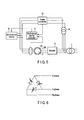
- FIG. 1 illustrates an example of a configuration of a variable speed electric system including a secondary over-voltage prevention device of a wound-rotor inductive power generator according to an embodiment of the present invention.
- the same reference numerals as in FIGS. 4 and 5 denote the same elements.
- the variable speed electric system comprises a main transformer 1, wound-rotor inductive power generator (variable speed electric device) 2, a converter (frequency converter) 3, a chopper circuit 4, an inverter 5, a transformer 6, a first short-circuit device 7, a second short-circuit device 8, a short-circuit device controller 9, a breaker 11, and a control unit 12.
- the chopper circuit 4 comprises a capacitor and an over-voltage suppression chopper (DC chopper unit).
- the converter 3, chopper circuit 4 and inverter 5 form a variable frequency power supply.
- the first short-circuit device 7, second short-circuit device 8, and short-circuit device controller 9 forms the secondary over-voltage prevention device.
- the wound-rotor inductive power generator 2 is connected to a motor such as a waterwheel, pump-turbine, or pinwheel not shown in the drawings on the rotation axis.
- the main transformer 1 performs voltage conversion between the variable speed electric system and the electric power system.
- the wound-rotor inductive power generator 2 is connected to the electric power system through the main transformer 1.
- the converter 3 supplies rectified voltage to the DC chopper unit of the chopper circuit 4.
- the chopper circuit 4 supplies a DC voltage to the inverter 5.
- the inverter 5 converts an output of the wound-rotor inductive power generator 2 and supplies an excitation power to a secondary winding of the wound-rotor inductive power generator 2.
- the transformer 6 transforms the output of the wound-rotor inductive power generator 2 so as to conform to the rated value of the converter 3.
- the first short-circuit device 7 is connected to each excitation power supply line connected to the secondary winding of the wound-rotor inductive power generator 2.
- the first short-circuit device 7 is controlled by the short-circuit device controller 9 to perform a short-circuit operation.
- the short-circuit operation is canceled by the variable frequency power supply after the fault in the electric power system is resolved.
- the current flowing through the breaker 11 becomes zero, thereby ensuring blocking a fault current by the breaker 11.
- the first short-circuit device 7 is formed using a separately-excited element such as a thyristor as shown in FIG. 6 .
- the second short-circuit device 8 is connected to each excitation power supply line connected to the secondary winding of the wound-rotor inductive power generator 2.
- the second short-circuit device 8 performs a short-circuit operation under the same condition as for the first short-circuit device 7, and is inactivated after the first short-circuit device 7 is inactivated.
- an over-current or over-voltage is prevented from occurring in the variable frequency power supply even when the first short-circuit device 7 is inactivated.
- the second short-circuit device 8 is formed by a self-excited element, a resistance, an inductance, a plurality of rectifiers, and a rectifier dedicated for commutation, as shown in FIG. 7 .
- the short-circuit device controller 9 obtains a measured value of a current in the excitation power supply line and a measured value of voltage of the DC chopper unit of the chopper circuit 4 to detect a fault current based on the measured values, or to control executing or canceling short-circuit operations of the short-circuit devices 7 and 8.
- the short-circuit device controller 9 controls the short-circuit devices 7 and 8 to perform short-circuit operation and stops the operations of the inverter 5 and the converter 3 at the same time, stops the operation of the first short-circuit device 7 at the time when the current flowing through the first short-circuit device 7 decays to zero, and then stops the operation of the second short-circuit device 8 after a short-circuit current is shunted to the second short-circuit device 8 for a predetermined period of time.
- the breaker 11 is used to block the primary power supply line of the wound-rotor inductive power generator 2 under the control of the control unit 12.
- the control unit 12 controls the entire system of the embodiment.
- the short-circuit device controller 9 detects the over-voltage through the secondary circuit at the time T1. Upon the detection of the over-voltage, the short-circuit device controller 9 activates the first short-circuit device 7 and the second short-circuit device 8 and steps the operations of the converter 3 and the inverter 5 at the same time.
- the short-circuit device controller 9 controls the inverter 5 to apply an inverse voltage to the first short-circuit device 7 at the time when a current flowing through the first short-circuit device 7 drops below a current value P (for example, a value smaller than 1.3 times the rated value of the inverter 5) which is a condition for resetting the first short-circuit device 7, and immediately after the application of the inverse current, sets the current flowing through the first short-circuit device 7 to be zero. Then, the short-circuit device controller 9 turns off the first short-circuit device 7 at the time T2 after a lapse of a predetermined time.
- a current value P for example, a value smaller than 1.3 times the rated value of the inverter 5
- the current flowing through the first short-circuit device 7 may flow into the inverter 5.
- the inverter 5 applies a reverse-phased voltage to the first short-circuit device 7 to inactivate the first short-circuit device 7 to reduce the amount of current to be commuted to the inverter 5. Accordingly, the inverter 5 restarts operation at the time T3 without the current flowing into the inverter 5 being an over-current again.
- the rated capacity of the converter 3 or the inverter 5 is determined based on the voltage set by the slip frequency during normal operation and the current during the rated operation, thereby eliminating the necessity for providing a large amount of capacity.
- the first short-circuit device 7 and the second short-circuit device 8 can be designed with a short-time rating, thereby miniaturizing the devices.
- the transitional DC current flowing through the first short-circuit device 7 is a transitional current flowing through the secondary-winding side
- the current flowing through the primary side is an AC current. Accordingly, the resistance between the rotor R2 of the wound-rotor inductive power generator 2 and the short-circuit device is greater than the resistance between the point of failure and the stator 2S of the wound-rotor inductive power generator 2, and the rate of decay of a transitional DC current at the primary side is slower than that of transitional DC at the secondary-winding side. As a result, the current flowing through the breaker 11 at the primary side is prevented from not reaching zero.
- variable speed electric system merely comprising a converter with a rated capacity determined based on the normal operation
- the first short-circuit device 7 is not reactivated after being stopped by the operation of the second short-circuit device 8, thereby ensuring continuous operation of the variable speed electric system.
- an over-voltage prevention device which is capable of recovering from a fault in the electric power system within a short time and ensuring continuous operation with a simple structure.
Landscapes
- Engineering & Computer Science (AREA)
- Power Engineering (AREA)
- Control Of Eletrric Generators (AREA)
Abstract
Description
- Embodiments described herein relate generally to an over-voltage prevention device which protects a frequency converter or a secondary winding of a wound-rotor induction machine from an over-voltage.
- Generally, in variable speed motor systems adopting an inductor as a power generation motor, an accidental over-voltage or over-current may be induced to a secondary-winding side of a power generator due to a problem on the electric power system, and a power converter which supplies an excitation current having a variable frequency may be damaged as a result of the induced over-current. Over-current and over-voltage prevention methods applying a short-circuit device are generally used to prevent the above problems.
- The over-current and over-voltage prevention methods applying a short-circuit device of the variable speed motor systems generally utilize an over-voltage prevention device comprising a short-circuit device connected to a three-phase electric device to be protected from an over-voltage in which thyristor valves, each having thyristors connected in series, are connected by a delta connection, a flip-flop to be set by an over-voltage being applied to the three-phase electric device, an AND circuit to provide a trigger signal to the thyristor valves under an AND condition of a forward voltage signal of the thyristor valves and an output of the flip-flop, a current detector which detects a current of each thyristor valve, and a means for resetting the flip-flop under a condition where an output of the current detector is zero for a predetermined period.
- In the aforementioned over-current and over-voltage prevention methods of the variable speed motor systems, when a problem occurs on the electric power system, a transitional over-voltage or over-current occurs for either grounding or inter-short-circuiting in the variable speed motor systems. In this case, an over-voltage or over-current flows into the system in comparison with the normal operation, and an over-voltage or over-current is induced to a secondary-winding side of a wound-rotor induction machine. If the secondary-winding side of the induction machine does not have a short circuit device, an over-voltage or over-current directly flows into the power converter. To avoid this, it is necessary to provide a large-capacity converter in the case of a fault in the electric power system, which rarely occurs.
- One of the solutions to this problem is to adopt a power generator system in which a secondary-winding side of a power generator is short-circuited by a first short-
circuit device 7 having a small impedance, as shown inFIG. 4 . The first short-circuit device 7 has a circuit structure as shown inFIG. 6 . With the first short-circuit device 7, in a band where a slip frequency of a motor is large, over-current flowing into the over-voltage prevention device significantly increases, and accordingly, apower converter 10, the capacity of which is determined based on a voltage, and a current in normal operation cannot open the over-voltage prevention device, and the secondary-winding side of the power generator cannot recover from the short-circuited status, thereby failing to ensure continuous operation. - Another solution is to adopt a power generator system in which a secondary-winding side of a power generator is resistance short-circuited by a second short-
circuit device 8 having a minute impedance greater than the impedance of the first short-circuit device 7, as shown inFIG. 5 . The second short-circuit device 8 has a circuit structure as shown inFIG. 7 . If the resistance of the second short-circuit device 8 is sufficiently small, resistance R2 from windings of a rotor of the power generator to the short-circuit device 8 becomes sufficiently smaller than resistance R1 from a point of failure caused by a fault in the electric power system to windings of a stator of the power generator. Accordingly, a transitional DC current flowing into the second short-circuit device 8 of the secondary-winding side of the power generator, i.e., the decay rate of a transitional AC current generated at the primary side of the power generator, becomes slower than the decay rate of the transitional DC current flowing through the primary side of the power generator. In this case, the current becomes zero in abreaker 11, and thebreaker 11 can be opened. However, if the resistance of the second short-circuit device is large, and resistance R2 becomes greater than R1, the aforementioned relation of decay rates will be inversed. In this case, the current of the primary side does not become zero, and thebreaker 11 cannot block the current. - Under the above circumstances, it is desirable to provide an over-voltage prevention device, which is capable of recovering from a failure in the electric power system within a short time and ensuring continuous operation with a simple structure.
- In general, according to one embodiment, an over-voltage prevention device is provided between a secondary-winding side of a wound-rotor induction machine and a frequency converter configured to excite the secondary-winding side of the wound-rotor induction machine through a three-phase excitation power supply line. The over-voltage prevention device includes a first short-circuit device having a function of short-circuiting between phases of the excitation power supply line, and a second short-circuit device having a function of short-circuiting between phases of the excitation power supply line with a short-circuit impedance greater than a short-circuit impedance of the first short-circuit device.
- The invention can be more fully understood from the following detailed description when taken in conjunction with the accompanying drawings, in which:
-
FIG. 1 illustrates an example of a configuration of a variable speed electric system including a secondary over-voltage prevention device of a wound-rotor inductive power generator according to an embodiment; -
FIG. 2 is a timing chart that shows a driving signal of a first short-circuit device or the like according to the embodiment; -
FIG. 3 is a timing chart that shows a driving signal of a second short-circuit device or the like according to the embodiment; -
FIG. 4 illustrates an example of a configuration of the variable speed electric system in which only the first short-circuit device is provided; -
FIG. 5 illustrates an example of a configuration of the variable speed electric system in which only the second short-circuit device is provided; -
FIG. 6 illustrates a circuit structure of the first short-circuit device; and -
FIG. 7 illustrates a circuit structure of the second short-circuit device. - Hereinafter, embodiments will be described with reference to
FIG. 1 to FIG. 3 . -
FIG. 1 illustrates an example of a configuration of a variable speed electric system including a secondary over-voltage prevention device of a wound-rotor inductive power generator according to an embodiment of the present invention. InFIG. 1 , the same reference numerals as inFIGS. 4 and5 denote the same elements. - As shown in
FIG. 1 , the variable speed electric system comprises a main transformer 1, wound-rotor inductive power generator (variable speed electric device) 2, a converter (frequency converter) 3, a chopper circuit 4, aninverter 5, atransformer 6, a first short-circuit device 7, a second short-circuit device 8, a short-circuit device controller 9, abreaker 11, and acontrol unit 12. The chopper circuit 4 comprises a capacitor and an over-voltage suppression chopper (DC chopper unit). Theconverter 3, chopper circuit 4 and inverter 5 form a variable frequency power supply. The first short-circuit device 7, second short-circuit device 8, and short-circuit device controller 9 forms the secondary over-voltage prevention device. - The wound-rotor
inductive power generator 2 is connected to a motor such as a waterwheel, pump-turbine, or pinwheel not shown in the drawings on the rotation axis. - The main transformer 1 performs voltage conversion between the variable speed electric system and the electric power system.
- The wound-rotor
inductive power generator 2 is connected to the electric power system through the main transformer 1. - The
converter 3 supplies rectified voltage to the DC chopper unit of the chopper circuit 4. - The chopper circuit 4 supplies a DC voltage to the
inverter 5. - The
inverter 5 converts an output of the wound-rotorinductive power generator 2 and supplies an excitation power to a secondary winding of the wound-rotorinductive power generator 2. - The
transformer 6 transforms the output of the wound-rotorinductive power generator 2 so as to conform to the rated value of theconverter 3. - The first short-
circuit device 7 is connected to each excitation power supply line connected to the secondary winding of the wound-rotorinductive power generator 2. During a fault in the electric power system, when a current flowing through the excitation power supply line is greater than a set value, and a voltage of the DC chopper unit of the chopper circuit 4 is greater than a set value, the first short-circuit device 7 is controlled by the short-circuit device controller 9 to perform a short-circuit operation. The short-circuit operation is canceled by the variable frequency power supply after the fault in the electric power system is resolved. As a result of the operation of the first short-circuit device 7, the current flowing through thebreaker 11 becomes zero, thereby ensuring blocking a fault current by thebreaker 11. The first short-circuit device 7 is formed using a separately-excited element such as a thyristor as shown inFIG. 6 . - The second short-
circuit device 8 is connected to each excitation power supply line connected to the secondary winding of the wound-rotorinductive power generator 2. The second short-circuit device 8 performs a short-circuit operation under the same condition as for the first short-circuit device 7, and is inactivated after the first short-circuit device 7 is inactivated. As a result of the operation of the second short-circuit device 8, an over-current or over-voltage is prevented from occurring in the variable frequency power supply even when the first short-circuit device 7 is inactivated. The second short-circuit device 8 is formed by a self-excited element, a resistance, an inductance, a plurality of rectifiers, and a rectifier dedicated for commutation, as shown inFIG. 7 . - The short-
circuit device controller 9 obtains a measured value of a current in the excitation power supply line and a measured value of voltage of the DC chopper unit of the chopper circuit 4 to detect a fault current based on the measured values, or to control executing or canceling short-circuit operations of the short-circuit devices circuit device controller 9 controls the short-circuit devices inverter 5 and theconverter 3 at the same time, stops the operation of the first short-circuit device 7 at the time when the current flowing through the first short-circuit device 7 decays to zero, and then stops the operation of the second short-circuit device 8 after a short-circuit current is shunted to the second short-circuit device 8 for a predetermined period of time. - The
breaker 11 is used to block the primary power supply line of the wound-rotorinductive power generator 2 under the control of thecontrol unit 12. - The
control unit 12 controls the entire system of the embodiment. - Next, the operation of the secondary over-voltage prevention device at the time of a fault in the electric power system is explained with reference to the timing charts of
FIGS. 2 and3 . - For instance, if a voltage affected to a
stator 2S of the wound-rotorinductive power generator 2 greatly changes due to a three-phase ground fault occurring in the electric power system, an over-voltage is induced to arotor 2R. The short-circuit device controller 9 detects the over-voltage through the secondary circuit at the time T1. Upon the detection of the over-voltage, the short-circuit device controller 9 activates the first short-circuit device 7 and the second short-circuit device 8 and steps the operations of theconverter 3 and theinverter 5 at the same time. - When the fault is eliminated, and the over-voltage is decayed, a current flowing through the first short-
circuit device 7 will gradually decay, as shown inFIG. 2 . In this example, the short-circuit device controller 9 controls theinverter 5 to apply an inverse voltage to the first short-circuit device 7 at the time when a current flowing through the first short-circuit device 7 drops below a current value P (for example, a value smaller than 1.3 times the rated value of the inverter 5) which is a condition for resetting the first short-circuit device 7, and immediately after the application of the inverse current, sets the current flowing through the first short-circuit device 7 to be zero. Then, the short-circuit device controller 9 turns off the first short-circuit device 7 at the time T2 after a lapse of a predetermined time. - In this case, the current flowing through the first short-
circuit device 7 may flow into theinverter 5. However, since the second short-circuit device 8 is activated at that time, as shown inFIG. 3 , theinverter 5 applies a reverse-phased voltage to the first short-circuit device 7 to inactivate the first short-circuit device 7 to reduce the amount of current to be commuted to theinverter 5. Accordingly, theinverter 5 restarts operation at the time T3 without the current flowing into theinverter 5 being an over-current again. - According to the embodiment, since the first short-
circuit device 7 and the second short-circuit device 8 can sustain an over-voltage and over-current occurring at the time of a fault in the electric power system, the rated capacity of theconverter 3 or theinverter 5 is determined based on the voltage set by the slip frequency during normal operation and the current during the rated operation, thereby eliminating the necessity for providing a large amount of capacity. In addition, the first short-circuit device 7 and the second short-circuit device 8 can be designed with a short-time rating, thereby miniaturizing the devices. - In the embodiment, since the transitional DC current flowing through the first short-
circuit device 7 is a transitional current flowing through the secondary-winding side, the current flowing through the primary side is an AC current. Accordingly, the resistance between the rotor R2 of the wound-rotorinductive power generator 2 and the short-circuit device is greater than the resistance between the point of failure and thestator 2S of the wound-rotorinductive power generator 2, and the rate of decay of a transitional DC current at the primary side is slower than that of transitional DC at the secondary-winding side. As a result, the current flowing through thebreaker 11 at the primary side is prevented from not reaching zero. - Furthermore, with the aforementioned variable speed electric system merely comprising a converter with a rated capacity determined based on the normal operation, the first short-
circuit device 7 is not reactivated after being stopped by the operation of the second short-circuit device 8, thereby ensuring continuous operation of the variable speed electric system. - As stated above, according to the aforementioned embodiments, it is possible to provide an over-voltage prevention device, which is capable of recovering from a fault in the electric power system within a short time and ensuring continuous operation with a simple structure.
- While certain embodiments have been described, these embodiments have been presented by way of example only, and are not intended to limit the scope of the inventions. Indeed, the novel embodiments described herein may be embodied in a variety of other forms; furthermore, various omissions, substitutions and changes in the form of the embodiments described herein may be made without departing from the spirit of the inventions. The accompanying claims and their equivalents are intended to cover such forms or modifications as would fall within the scope and spirit of the inventions.
Claims (4)
- An over-voltage prevention device (7 to 9) provided between a secondary-winding side of a wound-rotor induction machine (2) and a frequency converter (3) configured to excite the secondary-winding side of the wound-rotor induction machine (2) through a three-phase excitation power supply line, the over-voltage prevention device (7 to 9) characterized by comprising:a first short-circuit device (7) having a function of short-circuiting between phases of the excitation power supply line; anda second short-circuit device (8) having a function of short-circuiting between phases of the excitation power supply line with a short-circuit impedance greater than a short-circuit impedance of the first short-circuit device (7).
- The over-voltage prevention device (7 to 9) according to claim 1, characterized in that:the first short-circuit device (7) comprises a separately-excited element; andthe second short-circuit device (8) comprises a self-excited element, a resistance, and an inductance.
- The over-voltage prevention device (7 to 9) according to claim 1, characterized by further comprising a control unit (9) configured to activate the first short-circuit device (7) at a time of a fault in an electric power system, and to inactivate the first short-circuit device (7) by a variable frequency power supply after the fault is eliminated.
- The over-voltage prevention device (7 to 9) according to claim 3, characterized in that the control unit (9) is further configured to activate the second short-circuit device (8) at a time of a system fault, and to inactivate the second short-circuit device (8) after releasing the first short-circuit device (7).
Applications Claiming Priority (1)
| Application Number | Priority Date | Filing Date | Title |
|---|---|---|---|
| JP2014022376A JP6158109B2 (en) | 2014-02-07 | 2014-02-07 | Overvoltage protection device |
Publications (2)
| Publication Number | Publication Date |
|---|---|
| EP2905858A1 true EP2905858A1 (en) | 2015-08-12 |
| EP2905858B1 EP2905858B1 (en) | 2017-03-22 |
Family
ID=52444217
Family Applications (1)
| Application Number | Title | Priority Date | Filing Date |
|---|---|---|---|
| EP15153940.0A Active EP2905858B1 (en) | 2014-02-07 | 2015-02-05 | Over-voltage prevention device |
Country Status (4)
| Country | Link |
|---|---|
| US (1) | US9478972B2 (en) |
| EP (1) | EP2905858B1 (en) |
| JP (1) | JP6158109B2 (en) |
| CN (1) | CN104836206B (en) |
Cited By (2)
| Publication number | Priority date | Publication date | Assignee | Title |
|---|---|---|---|---|
| EP3379717A3 (en) * | 2017-03-24 | 2018-12-19 | Kabushiki Kaisha Toshiba | Variable-speed pumped storage power system and variable-speed pumped storage power method |
| EP3499704A4 (en) * | 2016-08-09 | 2020-04-29 | Hitachi Automotive Systems, Ltd. | INDUCED VOLTAGE SUPPRESSION DEVICE, MOTOR SYSTEM, AND POWER CONVERSION SYSTEM |
Families Citing this family (4)
| Publication number | Priority date | Publication date | Assignee | Title |
|---|---|---|---|---|
| JP6640635B2 (en) * | 2016-03-28 | 2020-02-05 | 株式会社東芝 | Overvoltage protection device for variable speed pumped storage power generation system |
| JP6346393B1 (en) * | 2016-11-25 | 2018-06-20 | 株式会社東芝 | Overvoltage protection device for variable speed power generation system |
| CN107299880B (en) * | 2017-08-01 | 2019-03-26 | 长沙学院 | A kind of permanent magnet direct-drive wind power generation plant |
| EP3888210A1 (en) * | 2018-11-30 | 2021-10-06 | Innovative Power Solutions, LLC | Electrical system redundant overvoltage protection |
Citations (4)
| Publication number | Priority date | Publication date | Assignee | Title |
|---|---|---|---|---|
| JPH0767393A (en) * | 1993-08-24 | 1995-03-10 | Tokyo Electric Power Co Inc:The | Overvoltage protection device for variable speed pumped storage generation system |
| EP1499009A1 (en) * | 2003-07-15 | 2005-01-19 | Gamesa Eolica, S.A. (Sociedad Unipersonal) | Control and protection of a doubly-fed induction generator system |
| US20080304188A1 (en) * | 2007-06-05 | 2008-12-11 | Hitachi, Ltd. | Wind Power Generation System and Control Method Thereof |
| WO2010045964A1 (en) * | 2008-10-20 | 2010-04-29 | Woodward Seg Gmbh & Co. Kg | Protection system of a doubly-fed induction machine |
Family Cites Families (8)
| Publication number | Priority date | Publication date | Assignee | Title |
|---|---|---|---|---|
| JPS53149613A (en) * | 1977-06-01 | 1978-12-27 | Hitachi Ltd | Protective device of over voltage in semiconductor device |
| JP2703566B2 (en) * | 1988-08-30 | 1998-01-26 | 株式会社日立製作所 | AC excitation synchronous machine controller |
| JP2695958B2 (en) * | 1990-03-02 | 1998-01-14 | 東京電力株式会社 | Secondary overvoltage protection device for wound induction machines |
| JP2695959B2 (en) * | 1990-03-05 | 1998-01-14 | 東京電力株式会社 | Control device for winding induction machine |
| JPH0654444A (en) | 1992-07-24 | 1994-02-25 | Toshiba Corp | Overvoltage protection device |
| JPH08317694A (en) * | 1995-05-19 | 1996-11-29 | Tokyo Electric Power Co Inc:The | Overvoltage protection device |
| EP2280166A1 (en) * | 2008-03-28 | 2011-02-02 | Ingeteam Energy, S.A. | Wind turbine operation method and system |
| CN102112737B (en) * | 2009-02-20 | 2013-07-17 | 三菱重工业株式会社 | Wind driven generator and method of controlling same |
-
2014
- 2014-02-07 JP JP2014022376A patent/JP6158109B2/en active Active
-
2015
- 2015-01-20 CN CN201510028699.7A patent/CN104836206B/en active Active
- 2015-02-05 EP EP15153940.0A patent/EP2905858B1/en active Active
- 2015-02-06 US US14/615,897 patent/US9478972B2/en active Active
Patent Citations (4)
| Publication number | Priority date | Publication date | Assignee | Title |
|---|---|---|---|---|
| JPH0767393A (en) * | 1993-08-24 | 1995-03-10 | Tokyo Electric Power Co Inc:The | Overvoltage protection device for variable speed pumped storage generation system |
| EP1499009A1 (en) * | 2003-07-15 | 2005-01-19 | Gamesa Eolica, S.A. (Sociedad Unipersonal) | Control and protection of a doubly-fed induction generator system |
| US20080304188A1 (en) * | 2007-06-05 | 2008-12-11 | Hitachi, Ltd. | Wind Power Generation System and Control Method Thereof |
| WO2010045964A1 (en) * | 2008-10-20 | 2010-04-29 | Woodward Seg Gmbh & Co. Kg | Protection system of a doubly-fed induction machine |
Cited By (2)
| Publication number | Priority date | Publication date | Assignee | Title |
|---|---|---|---|---|
| EP3499704A4 (en) * | 2016-08-09 | 2020-04-29 | Hitachi Automotive Systems, Ltd. | INDUCED VOLTAGE SUPPRESSION DEVICE, MOTOR SYSTEM, AND POWER CONVERSION SYSTEM |
| EP3379717A3 (en) * | 2017-03-24 | 2018-12-19 | Kabushiki Kaisha Toshiba | Variable-speed pumped storage power system and variable-speed pumped storage power method |
Also Published As
| Publication number | Publication date |
|---|---|
| JP6158109B2 (en) | 2017-07-05 |
| US9478972B2 (en) | 2016-10-25 |
| CN104836206A (en) | 2015-08-12 |
| US20150229120A1 (en) | 2015-08-13 |
| CN104836206B (en) | 2018-05-08 |
| JP2015149860A (en) | 2015-08-20 |
| EP2905858B1 (en) | 2017-03-22 |
Similar Documents
| Publication | Publication Date | Title |
|---|---|---|
| US9478972B2 (en) | Over-voltage prevention device | |
| JP6071912B2 (en) | Overvoltage protection device and current adjustment circuit | |
| US9140744B2 (en) | Doubly-fed induction generator system and the self-test method for the active crowbar circuit thereof | |
| US9680388B2 (en) | System and method for starting a variable frequency drive with reduced arc flash risk | |
| US20160268797A1 (en) | Variable frequency drive circuit with overvoltage protection | |
| CN110718898A (en) | Robust inverter topology | |
| JP2020080610A (en) | Motor drive system | |
| US9203341B2 (en) | Switch arrangement | |
| CN108631264A (en) | Variable-ratio water pumping electric generating system and variable-ratio draw water electricity-generating method | |
| CN107240912B (en) | Overvoltage Protection Device for Variable Speed Pumping Power Generation System | |
| JP5729597B2 (en) | Electric tool | |
| US9979279B2 (en) | DC-DC converter input voltage high-energy transient clamping topology | |
| JP2020065437A (en) | Overvoltage prevention apparatus for adjustable speed pumped storage power generation system | |
| JP6044854B2 (en) | Electric tool | |
| JPH0662600A (en) | Secondary excitation device | |
| JP6431777B2 (en) | Power converter | |
| CN100394684C (en) | Structure and method for protecting a converter device | |
| JPS603680Y2 (en) | Protection circuit for exciter for alternator | |
| JP6310790B2 (en) | AC voltage converter | |
| JPH07131928A (en) | AC excitation synchronous machine protection device, protection method, and AC excitation control device | |
| JP6585344B2 (en) | Exciter for synchronous machine and excitation stop method | |
| JP2014230334A (en) | Semiconductor electric power conversion system and rapid discharging method for dc intermediate capacitor | |
| JPH05168290A (en) | SELVIUS device | |
| JP2007151288A (en) | AC motor drive system | |
| JP2016096704A (en) | Excitation device for synchronous machine, power storage device, and excitation method for synchronous machine |
Legal Events
| Date | Code | Title | Description |
|---|---|---|---|
| PUAI | Public reference made under article 153(3) epc to a published international application that has entered the european phase |
Free format text: ORIGINAL CODE: 0009012 |
|
| 17P | Request for examination filed |
Effective date: 20150205 |
|
| AK | Designated contracting states |
Kind code of ref document: A1 Designated state(s): AL AT BE BG CH CY CZ DE DK EE ES FI FR GB GR HR HU IE IS IT LI LT LU LV MC MK MT NL NO PL PT RO RS SE SI SK SM TR |
|
| AX | Request for extension of the european patent |
Extension state: BA ME |
|
| GRAP | Despatch of communication of intention to grant a patent |
Free format text: ORIGINAL CODE: EPIDOSNIGR1 |
|
| RIC1 | Information provided on ipc code assigned before grant |
Ipc: H02P 9/00 20060101ALI20160927BHEP Ipc: H02H 7/09 20060101ALI20160927BHEP Ipc: H02H 9/04 20060101ALI20160927BHEP Ipc: H02H 7/06 20060101AFI20160927BHEP Ipc: H02P 29/024 20160101ALI20160927BHEP Ipc: H02H 7/10 20060101ALI20160927BHEP Ipc: H02P 9/10 20060101ALI20160927BHEP Ipc: H02J 3/38 20060101ALI20160927BHEP |
|
| INTG | Intention to grant announced |
Effective date: 20161019 |
|
| RAP1 | Party data changed (applicant data changed or rights of an application transferred) |
Owner name: KABUSHIKI KAISHA TOSHIBA |
|
| STAA | Information on the status of an ep patent application or granted ep patent |
Free format text: STATUS: GRANT OF PATENT IS INTENDED |
|
| GRAS | Grant fee paid |
Free format text: ORIGINAL CODE: EPIDOSNIGR3 |
|
| GRAA | (expected) grant |
Free format text: ORIGINAL CODE: 0009210 |
|
| STAA | Information on the status of an ep patent application or granted ep patent |
Free format text: STATUS: THE PATENT HAS BEEN GRANTED |
|
| AK | Designated contracting states |
Kind code of ref document: B1 Designated state(s): AL AT BE BG CH CY CZ DE DK EE ES FI FR GB GR HR HU IE IS IT LI LT LU LV MC MK MT NL NO PL PT RO RS SE SI SK SM TR |
|
| REG | Reference to a national code |
Ref country code: GB Ref legal event code: FG4D |
|
| REG | Reference to a national code |
Ref country code: CH Ref legal event code: EP Ref country code: CH Ref legal event code: NV Representative=s name: E. BLUM AND CO. AG PATENT- UND MARKENANWAELTE , CH |
|
| REG | Reference to a national code |
Ref country code: AT Ref legal event code: REF Ref document number: 878618 Country of ref document: AT Kind code of ref document: T Effective date: 20170415 |
|
| REG | Reference to a national code |
Ref country code: IE Ref legal event code: FG4D |
|
| REG | Reference to a national code |
Ref country code: DE Ref legal event code: R096 Ref document number: 602015001861 Country of ref document: DE |
|
| REG | Reference to a national code |
Ref country code: NL Ref legal event code: MP Effective date: 20170322 |
|
| PG25 | Lapsed in a contracting state [announced via postgrant information from national office to epo] |
Ref country code: GR Free format text: LAPSE BECAUSE OF FAILURE TO SUBMIT A TRANSLATION OF THE DESCRIPTION OR TO PAY THE FEE WITHIN THE PRESCRIBED TIME-LIMIT Effective date: 20170623 Ref country code: FI Free format text: LAPSE BECAUSE OF FAILURE TO SUBMIT A TRANSLATION OF THE DESCRIPTION OR TO PAY THE FEE WITHIN THE PRESCRIBED TIME-LIMIT Effective date: 20170322 Ref country code: NO Free format text: LAPSE BECAUSE OF FAILURE TO SUBMIT A TRANSLATION OF THE DESCRIPTION OR TO PAY THE FEE WITHIN THE PRESCRIBED TIME-LIMIT Effective date: 20170622 Ref country code: LT Free format text: LAPSE BECAUSE OF FAILURE TO SUBMIT A TRANSLATION OF THE DESCRIPTION OR TO PAY THE FEE WITHIN THE PRESCRIBED TIME-LIMIT Effective date: 20170322 Ref country code: HR Free format text: LAPSE BECAUSE OF FAILURE TO SUBMIT A TRANSLATION OF THE DESCRIPTION OR TO PAY THE FEE WITHIN THE PRESCRIBED TIME-LIMIT Effective date: 20170322 |
|
| REG | Reference to a national code |
Ref country code: LT Ref legal event code: MG4D |
|
| REG | Reference to a national code |
Ref country code: AT Ref legal event code: MK05 Ref document number: 878618 Country of ref document: AT Kind code of ref document: T Effective date: 20170322 |
|
| PG25 | Lapsed in a contracting state [announced via postgrant information from national office to epo] |
Ref country code: RS Free format text: LAPSE BECAUSE OF FAILURE TO SUBMIT A TRANSLATION OF THE DESCRIPTION OR TO PAY THE FEE WITHIN THE PRESCRIBED TIME-LIMIT Effective date: 20170322 Ref country code: BG Free format text: LAPSE BECAUSE OF FAILURE TO SUBMIT A TRANSLATION OF THE DESCRIPTION OR TO PAY THE FEE WITHIN THE PRESCRIBED TIME-LIMIT Effective date: 20170622 Ref country code: LV Free format text: LAPSE BECAUSE OF FAILURE TO SUBMIT A TRANSLATION OF THE DESCRIPTION OR TO PAY THE FEE WITHIN THE PRESCRIBED TIME-LIMIT Effective date: 20170322 Ref country code: SE Free format text: LAPSE BECAUSE OF FAILURE TO SUBMIT A TRANSLATION OF THE DESCRIPTION OR TO PAY THE FEE WITHIN THE PRESCRIBED TIME-LIMIT Effective date: 20170322 |
|
| PG25 | Lapsed in a contracting state [announced via postgrant information from national office to epo] |
Ref country code: NL Free format text: LAPSE BECAUSE OF FAILURE TO SUBMIT A TRANSLATION OF THE DESCRIPTION OR TO PAY THE FEE WITHIN THE PRESCRIBED TIME-LIMIT Effective date: 20170322 |
|
| PG25 | Lapsed in a contracting state [announced via postgrant information from national office to epo] |
Ref country code: EE Free format text: LAPSE BECAUSE OF FAILURE TO SUBMIT A TRANSLATION OF THE DESCRIPTION OR TO PAY THE FEE WITHIN THE PRESCRIBED TIME-LIMIT Effective date: 20170322 Ref country code: ES Free format text: LAPSE BECAUSE OF FAILURE TO SUBMIT A TRANSLATION OF THE DESCRIPTION OR TO PAY THE FEE WITHIN THE PRESCRIBED TIME-LIMIT Effective date: 20170322 Ref country code: CZ Free format text: LAPSE BECAUSE OF FAILURE TO SUBMIT A TRANSLATION OF THE DESCRIPTION OR TO PAY THE FEE WITHIN THE PRESCRIBED TIME-LIMIT Effective date: 20170322 Ref country code: AT Free format text: LAPSE BECAUSE OF FAILURE TO SUBMIT A TRANSLATION OF THE DESCRIPTION OR TO PAY THE FEE WITHIN THE PRESCRIBED TIME-LIMIT Effective date: 20170322 Ref country code: RO Free format text: LAPSE BECAUSE OF FAILURE TO SUBMIT A TRANSLATION OF THE DESCRIPTION OR TO PAY THE FEE WITHIN THE PRESCRIBED TIME-LIMIT Effective date: 20170322 Ref country code: SK Free format text: LAPSE BECAUSE OF FAILURE TO SUBMIT A TRANSLATION OF THE DESCRIPTION OR TO PAY THE FEE WITHIN THE PRESCRIBED TIME-LIMIT Effective date: 20170322 |
|
| PG25 | Lapsed in a contracting state [announced via postgrant information from national office to epo] |
Ref country code: PL Free format text: LAPSE BECAUSE OF FAILURE TO SUBMIT A TRANSLATION OF THE DESCRIPTION OR TO PAY THE FEE WITHIN THE PRESCRIBED TIME-LIMIT Effective date: 20170322 Ref country code: IS Free format text: LAPSE BECAUSE OF FAILURE TO SUBMIT A TRANSLATION OF THE DESCRIPTION OR TO PAY THE FEE WITHIN THE PRESCRIBED TIME-LIMIT Effective date: 20170722 Ref country code: SM Free format text: LAPSE BECAUSE OF FAILURE TO SUBMIT A TRANSLATION OF THE DESCRIPTION OR TO PAY THE FEE WITHIN THE PRESCRIBED TIME-LIMIT Effective date: 20170322 Ref country code: PT Free format text: LAPSE BECAUSE OF FAILURE TO SUBMIT A TRANSLATION OF THE DESCRIPTION OR TO PAY THE FEE WITHIN THE PRESCRIBED TIME-LIMIT Effective date: 20170724 |
|
| REG | Reference to a national code |
Ref country code: DE Ref legal event code: R097 Ref document number: 602015001861 Country of ref document: DE |
|
| PLBE | No opposition filed within time limit |
Free format text: ORIGINAL CODE: 0009261 |
|
| STAA | Information on the status of an ep patent application or granted ep patent |
Free format text: STATUS: NO OPPOSITION FILED WITHIN TIME LIMIT |
|
| PG25 | Lapsed in a contracting state [announced via postgrant information from national office to epo] |
Ref country code: DK Free format text: LAPSE BECAUSE OF FAILURE TO SUBMIT A TRANSLATION OF THE DESCRIPTION OR TO PAY THE FEE WITHIN THE PRESCRIBED TIME-LIMIT Effective date: 20170322 |
|
| 26N | No opposition filed |
Effective date: 20180102 |
|
| PG25 | Lapsed in a contracting state [announced via postgrant information from national office to epo] |
Ref country code: SI Free format text: LAPSE BECAUSE OF FAILURE TO SUBMIT A TRANSLATION OF THE DESCRIPTION OR TO PAY THE FEE WITHIN THE PRESCRIBED TIME-LIMIT Effective date: 20170322 Ref country code: IT Free format text: LAPSE BECAUSE OF FAILURE TO SUBMIT A TRANSLATION OF THE DESCRIPTION OR TO PAY THE FEE WITHIN THE PRESCRIBED TIME-LIMIT Effective date: 20170322 |
|
| PG25 | Lapsed in a contracting state [announced via postgrant information from national office to epo] |
Ref country code: MC Free format text: LAPSE BECAUSE OF FAILURE TO SUBMIT A TRANSLATION OF THE DESCRIPTION OR TO PAY THE FEE WITHIN THE PRESCRIBED TIME-LIMIT Effective date: 20170322 |
|
| REG | Reference to a national code |
Ref country code: IE Ref legal event code: MM4A |
|
| REG | Reference to a national code |
Ref country code: BE Ref legal event code: MM Effective date: 20180228 |
|
| PG25 | Lapsed in a contracting state [announced via postgrant information from national office to epo] |
Ref country code: LU Free format text: LAPSE BECAUSE OF NON-PAYMENT OF DUE FEES Effective date: 20180205 |
|
| REG | Reference to a national code |
Ref country code: FR Ref legal event code: ST Effective date: 20181031 |
|
| PG25 | Lapsed in a contracting state [announced via postgrant information from national office to epo] |
Ref country code: IE Free format text: LAPSE BECAUSE OF NON-PAYMENT OF DUE FEES Effective date: 20180205 |
|
| PG25 | Lapsed in a contracting state [announced via postgrant information from national office to epo] |
Ref country code: FR Free format text: LAPSE BECAUSE OF NON-PAYMENT OF DUE FEES Effective date: 20180228 Ref country code: BE Free format text: LAPSE BECAUSE OF NON-PAYMENT OF DUE FEES Effective date: 20180228 |
|
| GBPC | Gb: european patent ceased through non-payment of renewal fee |
Effective date: 20190205 |
|
| PG25 | Lapsed in a contracting state [announced via postgrant information from national office to epo] |
Ref country code: GB Free format text: LAPSE BECAUSE OF NON-PAYMENT OF DUE FEES Effective date: 20190205 Ref country code: MT Free format text: LAPSE BECAUSE OF NON-PAYMENT OF DUE FEES Effective date: 20180205 |
|
| PG25 | Lapsed in a contracting state [announced via postgrant information from national office to epo] |
Ref country code: TR Free format text: LAPSE BECAUSE OF FAILURE TO SUBMIT A TRANSLATION OF THE DESCRIPTION OR TO PAY THE FEE WITHIN THE PRESCRIBED TIME-LIMIT Effective date: 20170322 |
|
| PG25 | Lapsed in a contracting state [announced via postgrant information from national office to epo] |
Ref country code: CY Free format text: LAPSE BECAUSE OF FAILURE TO SUBMIT A TRANSLATION OF THE DESCRIPTION OR TO PAY THE FEE WITHIN THE PRESCRIBED TIME-LIMIT Effective date: 20170322 Ref country code: HU Free format text: LAPSE BECAUSE OF FAILURE TO SUBMIT A TRANSLATION OF THE DESCRIPTION OR TO PAY THE FEE WITHIN THE PRESCRIBED TIME-LIMIT; INVALID AB INITIO Effective date: 20150205 Ref country code: MK Free format text: LAPSE BECAUSE OF NON-PAYMENT OF DUE FEES Effective date: 20170322 |
|
| PG25 | Lapsed in a contracting state [announced via postgrant information from national office to epo] |
Ref country code: AL Free format text: LAPSE BECAUSE OF FAILURE TO SUBMIT A TRANSLATION OF THE DESCRIPTION OR TO PAY THE FEE WITHIN THE PRESCRIBED TIME-LIMIT Effective date: 20170322 |
|
| REG | Reference to a national code |
Ref country code: CH Ref legal event code: U11 Free format text: ST27 STATUS EVENT CODE: U-0-0-U10-U11 (AS PROVIDED BY THE NATIONAL OFFICE) Effective date: 20260301 |
|
| PGFP | Annual fee paid to national office [announced via postgrant information from national office to epo] |
Ref country code: DE Payment date: 20251210 Year of fee payment: 12 |
|
| PGFP | Annual fee paid to national office [announced via postgrant information from national office to epo] |
Ref country code: CH Payment date: 20260301 Year of fee payment: 12 |