EP2905847A1 - Assembly - Google Patents
Assembly Download PDFInfo
- Publication number
- EP2905847A1 EP2905847A1 EP13843879.1A EP13843879A EP2905847A1 EP 2905847 A1 EP2905847 A1 EP 2905847A1 EP 13843879 A EP13843879 A EP 13843879A EP 2905847 A1 EP2905847 A1 EP 2905847A1
- Authority
- EP
- European Patent Office
- Prior art keywords
- receptacle
- contact
- housing
- battery
- connector
- Prior art date
- Legal status (The legal status is an assumption and is not a legal conclusion. Google has not performed a legal analysis and makes no representation as to the accuracy of the status listed.)
- Granted
Links
Images









Classifications
-
- H—ELECTRICITY
- H01—ELECTRIC ELEMENTS
- H01R—ELECTRICALLY-CONDUCTIVE CONNECTIONS; STRUCTURAL ASSOCIATIONS OF A PLURALITY OF MUTUALLY-INSULATED ELECTRICAL CONNECTING ELEMENTS; COUPLING DEVICES; CURRENT COLLECTORS
- H01R11/00—Individual connecting elements providing two or more spaced connecting locations for conductive members which are, or may be, thereby interconnected, e.g. end pieces for wires or cables supported by the wire or cable and having means for facilitating electrical connection to some other wire, terminal, or conductive member, blocks of binding posts
- H01R11/11—End pieces or tapping pieces for wires, supported by the wire and for facilitating electrical connection to some other wire, terminal or conductive member
- H01R11/28—End pieces consisting of a ferrule or sleeve
- H01R11/281—End pieces consisting of a ferrule or sleeve for connections to batteries
- H01R11/287—Intermediate parts between battery post and cable end piece
-
- H—ELECTRICITY
- H01—ELECTRIC ELEMENTS
- H01R—ELECTRICALLY-CONDUCTIVE CONNECTIONS; STRUCTURAL ASSOCIATIONS OF A PLURALITY OF MUTUALLY-INSULATED ELECTRICAL CONNECTING ELEMENTS; COUPLING DEVICES; CURRENT COLLECTORS
- H01R13/00—Details of coupling devices of the kinds covered by groups H01R12/70 or H01R24/00 - H01R33/00
- H01R13/73—Means for mounting coupling parts to apparatus or structures, e.g. to a wall
-
- H—ELECTRICITY
- H01—ELECTRIC ELEMENTS
- H01M—PROCESSES OR MEANS, e.g. BATTERIES, FOR THE DIRECT CONVERSION OF CHEMICAL ENERGY INTO ELECTRICAL ENERGY
- H01M50/00—Constructional details or processes of manufacture of the non-active parts of electrochemical cells other than fuel cells, e.g. hybrid cells
- H01M50/50—Current conducting connections for cells or batteries
-
- H—ELECTRICITY
- H01—ELECTRIC ELEMENTS
- H01M—PROCESSES OR MEANS, e.g. BATTERIES, FOR THE DIRECT CONVERSION OF CHEMICAL ENERGY INTO ELECTRICAL ENERGY
- H01M50/00—Constructional details or processes of manufacture of the non-active parts of electrochemical cells other than fuel cells, e.g. hybrid cells
- H01M50/50—Current conducting connections for cells or batteries
- H01M50/502—Interconnectors for connecting terminals of adjacent batteries; Interconnectors for connecting cells outside a battery casing
- H01M50/505—Interconnectors for connecting terminals of adjacent batteries; Interconnectors for connecting cells outside a battery casing comprising a single busbar
-
- H—ELECTRICITY
- H01—ELECTRIC ELEMENTS
- H01M—PROCESSES OR MEANS, e.g. BATTERIES, FOR THE DIRECT CONVERSION OF CHEMICAL ENERGY INTO ELECTRICAL ENERGY
- H01M50/00—Constructional details or processes of manufacture of the non-active parts of electrochemical cells other than fuel cells, e.g. hybrid cells
- H01M50/50—Current conducting connections for cells or batteries
- H01M50/502—Interconnectors for connecting terminals of adjacent batteries; Interconnectors for connecting cells outside a battery casing
- H01M50/514—Methods for interconnecting adjacent batteries or cells
- H01M50/517—Methods for interconnecting adjacent batteries or cells by fixing means, e.g. screws, rivets or bolts
-
- H—ELECTRICITY
- H01—ELECTRIC ELEMENTS
- H01M—PROCESSES OR MEANS, e.g. BATTERIES, FOR THE DIRECT CONVERSION OF CHEMICAL ENERGY INTO ELECTRICAL ENERGY
- H01M50/00—Constructional details or processes of manufacture of the non-active parts of electrochemical cells other than fuel cells, e.g. hybrid cells
- H01M50/50—Current conducting connections for cells or batteries
- H01M50/543—Terminals
- H01M50/547—Terminals characterised by the disposition of the terminals on the cells
- H01M50/55—Terminals characterised by the disposition of the terminals on the cells on the same side of the cell
-
- H—ELECTRICITY
- H01—ELECTRIC ELEMENTS
- H01M—PROCESSES OR MEANS, e.g. BATTERIES, FOR THE DIRECT CONVERSION OF CHEMICAL ENERGY INTO ELECTRICAL ENERGY
- H01M50/00—Constructional details or processes of manufacture of the non-active parts of electrochemical cells other than fuel cells, e.g. hybrid cells
- H01M50/50—Current conducting connections for cells or batteries
- H01M50/543—Terminals
- H01M50/552—Terminals characterised by their shape
- H01M50/553—Terminals adapted for prismatic, pouch or rectangular cells
-
- H—ELECTRICITY
- H01—ELECTRIC ELEMENTS
- H01R—ELECTRICALLY-CONDUCTIVE CONNECTIONS; STRUCTURAL ASSOCIATIONS OF A PLURALITY OF MUTUALLY-INSULATED ELECTRICAL CONNECTING ELEMENTS; COUPLING DEVICES; CURRENT COLLECTORS
- H01R4/00—Electrically-conductive connections between two or more conductive members in direct contact, i.e. touching one another; Means for effecting or maintaining such contact; Electrically-conductive connections having two or more spaced connecting locations for conductors and using contact members penetrating insulation
- H01R4/28—Clamped connections, spring connections
- H01R4/30—Clamped connections, spring connections utilising a screw or nut clamping member
- H01R4/34—Conductive members located under head of screw
-
- Y—GENERAL TAGGING OF NEW TECHNOLOGICAL DEVELOPMENTS; GENERAL TAGGING OF CROSS-SECTIONAL TECHNOLOGIES SPANNING OVER SEVERAL SECTIONS OF THE IPC; TECHNICAL SUBJECTS COVERED BY FORMER USPC CROSS-REFERENCE ART COLLECTIONS [XRACs] AND DIGESTS
- Y02—TECHNOLOGIES OR APPLICATIONS FOR MITIGATION OR ADAPTATION AGAINST CLIMATE CHANGE
- Y02E—REDUCTION OF GREENHOUSE GAS [GHG] EMISSIONS, RELATED TO ENERGY GENERATION, TRANSMISSION OR DISTRIBUTION
- Y02E60/00—Enabling technologies; Technologies with a potential or indirect contribution to GHG emissions mitigation
- Y02E60/10—Energy storage using batteries
Definitions
- the present invention relates to an assembly.
- Patent Literature 1 discloses a battery terminal connection connector 104 for connecting electric wires 100 to a battery post 103 of a battery terminal 102 of a battery 101.
- the battery terminal connection connector 104 includes a female connector housing 106 with a branch terminal 105 accommodated therein, and a male connector housing 108 for accommodating a connection terminal 107 connected to an end of the electric wires 100.
- an attachment hole 109 through which the battery post 103 can be inserted is formed in the branch terminal 105.
- the battery post 103 is inserted through the attachment hole 109 of the branch terminal 105 of the female connector housing 106 and then a nut 110 is screwed on the battery post 103.
- Patent Literature 1 Japanese Unexamined Patent Application Publication No. 2001-256956
- Patent Literature 1 there is a risk that when the nut 110 is screwed on the battery post 103, the female connector housing 106 could rotate with respect to the battery 101.
- An object of the invention of the present application is to provide a technique for preventing an electric connector from rotating relative to an object to be connected when the electric connector is screwed on the object to be connected.
- the present invention provides an assembly including: an electric connector including a contact with a bolt hole for bolting formed therein, and a housing attached to the contact; and an object to be connected having a first surface on which the contact of the electric connector is attached by the bolting, and a second surface roughly perpendicular to the first surface, in which the housing of the electric connector is formed so as to extend in an elongated shape along a tangent direction of an imaginary circle centered on a central axis of the bolt hole of the contact of the electric connector as viewed in a central axis direction of the bolt hole, and is capable of coming into contact with the second surface of the object to be connected at the time of the bolting.
- the housing of the electric connector is capable of being disposed relative to the object to be connected so that a lengthwise direction of the housing of the electric connector is roughly in parallel with the second surface of the object to be connected at the time of the bolting as viewed in the central axis direction.
- the housing of the electric connector is capable of being disposed relative to the object to be connected so that a lengthwise direction of the housing of the electric connector is roughly in parallel with the first surface of the object to be connected at the time of the bolting as viewed in a direction perpendicular to the second surface of the object to be connected.
- the contact of the electric connector includes a first contact section in which the bolt hole is formed, and a second contact section connected to the first contact section, the second contact section extending along the lengthwise direction of the housing of the electric connector.
- a lengthwise direction of the first contact section is roughly perpendicular to that of the second contact section.
- the contact of the electric connector is formed in a roughly L-shape.
- the housing of the electric connector accommodates the second contact section.
- the first and second contact sections connect to each other in a halfway part in the lengthwise direction of the housing of the electric connector.
- a thickness direction of the first contact section is roughly in parallel with that of the second contact section.
- a locking part for maintaining a connected state with a counterpart housing of a counterpart connector is formed.
- the object to be connected is a battery.
- the invention of the present application provides an advantageous effect that since the housing of the electric connector is effectively caught on the second surface of the object to be connected at the time of the bolting, rotation of the electric connector with respect to the object to be connected is prevented.
- FIG. 1 A first exemplary embodiment according to the present invention is explained hereinafter with reference to Figs. 1 to 24 .
- a battery unit 1 (assembled unit) includes a battery assembly 2 (assembly) and a connecting cable 3.
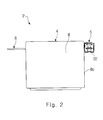
- Fig. 2 is a front view of the battery assembly 2
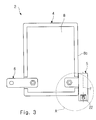
- Fig. 3 is a plan view of the battery assembly 2
- Fig. 4 is a side view of the battery assembly 2.
- the battery assembly 2 includes a battery 4 (object to be connected), a receptacle connector 5 (electric connector), a bus bar 6, and a plurality of nuts 7.
- the battery 4 includes a battery main body 8, a stacking rib 9, and a pair of battery terminal units 10.
- the battery main body 8 is formed in a roughly rectangular parallelepiped shape having an upper surface 8a (first surface), a front surface 8b, a right side surface 8c (second surface), a left side surface 8d, and a rear surface 8e. Therefore, the upper surface 8a is roughly perpendicular to the right side surface 8c.
- the stacking rib 9 is formed so as to protrude upward from the peripheral edge of the upper surface 8a and surround the upper surface 8a.
- the stacking rib 9 includes a front rib 9b corresponding to the front surface 8b, a right side rib 9c corresponding to the right side surface 8c, a left side rib 9d corresponding to the left side surface 8d, and a rear rib 9e corresponding to the rear surface 8e.
- the pair of battery terminal units 10 are formed on the upper surface 8a.
- Each battery terminal unit 10 is disposed in one of two corner parts 8f, which are two of four corner parts 8f of the upper surface 8a located near the front surface 8b.
- Each battery terminal unit 10 includes a battery terminal 11 and a battery post 12.
- each battery post 12 is formed in a male screw shape and disposed so as to protrude upward from the respective battery terminal 11.
- a battery terminal unit access slit 13 is formed so that a user can look in at the battery terminal unit 10 as he/she looks at the battery 4 in a direction perpendicular to the right side surface 8c.
- another battery terminal unit access slit 13 is formed in the left side rib 9d of the stacking rib 9.
- the right side surface 8c of the battery main body 8 extends upward beyond the upper surface 8a.
- the left side surface 8d of the battery main body 8 extends upward beyond the upper surface 8a.
- the connecting cable 3 includes a connecting cable main body 14 and a plug connector 15 (counterpart connector) attached to an end of the connecting cable main body 14.
- the connecting cable main body 14 includes a center conductor 14a and a cover material 14b covering the center conductor 14a.
- the plug connector 15 includes a plug contact 15a (counterpart contact) attached to the center conductor 14a, and a plug housing 15b that accommodates and holds the plug contact 15a.
- a lance 16 that is supported at both ends thereof is formed in the plug housing 15b.
- the lance 16 includes a locking claw 17.
- the receptacle connector 5 includes a receptacle contact 20 (contact) that is capable of coming into contact with the plug contact 15a of the plug connector 15 (see Fig. 7 ), and a receptacle housing 22 (housing) with a contact insertion hole 21 formed therein into which the receptacle contact 20 is inserted.
- a receptacle contact 20 contact
- a receptacle housing 22 housing
- the receptacle housing 22 is formed in an elongated shape in this exemplary embodiment.
- the receptacle contact 20 is formed in a roughly L-shape. That is, the receptacle contact 20 includes a bolting section 24 (first contact section) with a bolt hole 23 for bolting formed therein, and an accommodated section 25 (second contact section) that connects with the bolting section 24 and extends along a lengthwise direction of the receptacle housing 22.
- a lengthwise direction of the bolting section 24 is roughly perpendicular to that of the accommodated section 25.
- a direction in which the receptacle contact 20 is inserted into the contact insertion hole 21 of the receptacle housing 22 is indicated by an inserting direction D in this exemplary embodiment.
- a “lengthwise direction”, a “central axis direction” and a “crosswise direction” are defined here.
- the lengthwise direction means the lengthwise direction of the receptacle housing 22.
- the lengthwise direction includes the inserting direction D shown in Fig. 12 and a counter-inserting direction that is a direction opposite to the inserting direction D.
- the central axis direction means a central axis direction of the bolt hole 23.
- the central axis direction includes an upward direction and a downward direction.
- the crosswise direction is perpendicular to both the lengthwise direction and the central axis direction.
- the crosswise direction includes a bolting section protruding direction, which is a direction from the accommodated section 25 toward the bolting section 24, and a bolting section counter-protruding direction, which is a direction from the bolting section 24 toward the accommodated section 25.
- Figs. 16 and 17 show cross sections of the receptacle housing 22 in a simplified manner.
- the receptacle housing 22 has a roughly elongated rectangular parallelepiped external appearance.
- the receptacle housing 22 includes a housing main body 26 and a mating section 27.
- the housing main body 26 adjoins the counter-inserting direction side of the mating section 27.
- the mating section 27 adjoins the inserting direction side of the housing main body 26.
- the receptacle housing 22 is formed in a roughly tubular shape.
- the housing main body 26 includes a top plate 30, a bottom plate 31, a left side plate 32, a right press-fit holding part 33, a left press-fit holding part 34, and a lance 35.
- the top plate 30 and the bottom plate 31 are opposed to each other in the central axis direction.
- the top plate 30 is located above the bottom plate 31, and the bottom plate 31 is located below the top plate 30.
- a gap g is formed between the top plate 30 and the bottom plate 31.
- the gap g is slightly larger than the thickness of the receptacle contact 20 (see also Fig. 12 ).
- the top plate 30 has a lower surface 30a.
- the lower surface 30a is a surface that faces the bottom plate 31.
- the lance 35 is formed on the lower surface 30a.
- the lance 35 is formed to prevent the receptacle contact 20 from being removed.
- the lance 35 is formed so as to extend from the lower surface 30a of the top plate 30 in the inserting direction D in a cantilever shape.
- a lance claw 35a is formed at the free end of the lance 35.
- the bottom plate 31 has an upper surface 31a.
- the upper surface 31a is a surface that faces the top plate 30.
- An interference part insertion groove 36 is formed on the upper surface 31a.
- the interference part insertion groove 36 is formed on the counter-inserting direction side of the upper surface 31a.
- the upper side and the counter-inserting direction side of the interference part insertion groove 36 are opened.
- the interference part insertion groove 36 is formed in such a manner that its width in the crosswise direction gradually decreases in the inserting direction D.
- the bottom plate 31 has a right inner wall surface 36a (inner wall surface, restricting part) and a left inner wall surface 36b (inner wall surface, restricting part).
- the right inner wall surface 36a is an inner wall surface that defines the bolting section protruding direction side of the interference part insertion groove 36.
- the left inner wall surface 36b is an inner wall surface that defines the bolting section counter-protruding direction side of the interference part insertion groove 36.
- the right inner wall surface 36a and the left inner wall surface 36b are opposed to each other. Therefore, the gap between the right inner wall surface 36a and left inner wall surface 36b gradually decreases in the inserting direction D.
- the left side plate 32, the right press-fit holding part 33, and the left press-fit holding part 34 are all formed between the top plate 30 and the bottom plate 31.
- the left side plate 32 and the left press-fit holding part 34 define the bolting section counter-protruding direction side of the gap g.
- the left side plate 32 adjoins the counter-inserting direction side of the left press-fit holding part 34.
- the left press-fit holding part 34 adjoins the inserting direction D side of the left side plate 32.
- the right press-fit holding part 33 defines the bolting section protruding direction side of the gap g.
- the right press-fit holding part 33 and the left press-fit holding part 34 are opposed to each other in the crosswise direction.
- the right press-fit holding part 33 has a right press-fit holding surface 33a and a right contact insertion restricting surface 33b.
- the right press-fit holding surface 33a is a surface that faces the left press-fit holding part 34.
- the right contact insertion restricting surface 33b is a surface that faces in the counter-inserting direction.
- the left press-fit holding part 34 has a left press-fit holding surface 34a and a left contact insertion restricting surface 34b.
- the left press-fit holding surface 34a is a surface that faces the right press-fit holding part 33.
- the left contact insertion restricting surface 34b is a surface that faces in the counter-inserting direction.
- the contact insertion hole 21 is formed by the lower surface 30a of the top plate 30, the upper surface 31a of the bottom plate 31, the right press-fit holding surface 33a of the right press-fit holding part 33, and the left press-fit holding surface 34a of the left press-fit holding part 34.
- the lance claw 35a of the lance 35 is located inside the contact insertion hole 21.
- a lightening 37 may be formed as appropriate.
- the mating section 27 is formed so as to protrude from the housing main body 26 in the inserting direction D in a roughly rectangular-tube shape. As shown in Fig. 16 , the mating section 27 provides a mating space S in which the plug connector 15 is received. On a mating top plate 27a of the mating section 27, a lance locking surface 27b (locking part) on which a locking claw 17 of the lance 16 of the plug housing 15b of the plug connector 15 shown in Fig. 17 is caught is formed.
- the receptacle contact 20 is formed by a metal plate M having a somewhat large thickness.
- the receptacle contact 20 includes the bolting section 24 and the accommodated section 25.
- the receptacle contact 20 includes an interference part 44 in addition to the bolting section 24 and the accommodated section 25.
- the accommodated section 25 includes a held part 40, a tip part 41, and a base end part 42.
- the bolting section 24 is roughly in parallel with the accommodated section 25 in the thickness direction.
- the thickness direction of each of the bolting section 24 and the accommodated section 25 is in parallel with the central axis direction.
- the thickness direction of the interference part 44 is perpendicular to that of the base end part 42 and the like.
- the thickness direction of the interference part 44 is in parallel with the lengthwise direction.
- the base end part 42, the held part 40, and the tip part 41 are arranged in this listed order in the inserting direction D.
- the held part 40 is a part that is accommodated in the contact insertion hole 21 of the housing main body 26 of the receptacle housing 22 shown in Fig. 17 and held by the housing main body 26 of the receptacle housing 22.
- the held part 40 includes a right bulging part 40a bulging in the bolting section protruding direction and a left bulging part 40b bulging in the bolting section counter-protruding direction.
- the right bulging part 40a and the left bulging part 40b are formed near the tip part 41.
- the width in the crosswise direction of the contact insertion hole 21 between the right press-fit holding surface 33a of the right press-fit holding part 33 and the left press-fit holding surface 34a of the left press-fit holding part 34 shown in Fig. 17 is adjusted so as to be slightly smaller than the width in the crosswise direction of the held part 40 including the right bulging part 40a and the left bulging part 40b shown in Fig. 19 .
- the tip part 41 is a part that protrudes from the held part 40 in the inserting direction D and is capable of coming into contact with the plug contact 15a of the plug connector 15 (see Fig. 7 ).
- the base end part 42 is a part that protrudes from the held part 40 in the counter-inserting direction.
- the base end part 42 has a right shoulder surface 42a and a left shoulder surface 42b.
- the right shoulder surface 42a is located on the bolting section protruding direction side relative to the held part 40 and faces in the inserting direction D.
- the left shoulder surface 42b is located on the bolting section counter-protruding direction side relative to the held part 40 and faces in the inserting direction D.
- the bolting section 24 is a part that protrudes from the base end part 42 in the bolting section protruding direction. A bolt hole 23 for bolting is formed in the bolting section 24.
- the interference part 44 is a part that protrudes from the base end part 42.
- the interference part 44 protrudes in an obliquely downward direction with respect to the base end part 42.
- the interference part 44 protrudes from the base end part 42 in such a manner that the thickness direction of the interference part 44 is roughly perpendicular to that of the base end part 42. That is, the interference part 44 is formed so as to protrude downward from the base end part 42.
- the interference part 44 is disposed on the side opposite to the held part 40 across the base end part 42.
- the thickness direction of the interference part 44 is in parallel with the lengthwise direction.
- the interference part 44 has a right end surface 44a and a left end surface 44b.
- the right end surface 44a is an end surface that faces in the bolting section protruding direction.
- the left end surface 44b is an end surface that faces in the bolting section counter-protruding direction.
- a lance locking hole 45 is formed in the receptacle contact 20.
- the receptacle contact 20 has a lance locking surface 45a that defines the inserting direction D side of the lance locking hole 45.
- the lance locking surface 45a is located at roughly the center of the held part 40 in the lengthwise direction. In other words, the lance locking surface 45a, on which the lance claw 35a of the lance 35 is caught, is formed in the held part 40 of the receptacle contact 20.
- the receptacle contact 20 is firmly inserted into the gap g of the receptacle housing 22.
- the right shoulder surface 42a and the left shoulder surface 42b of the base end part 42 of the receptacle contact 20 shown in Fig. 19 are brought into contact with the right contact insertion restricting surface 33b of the right press-fit holding part 33 and the left contact insertion restricting surface 34b of the left press-fit holding part 34, respectively, of the receptacle housing 22 shown in Fig. 17 , thus preventing the receptacle contact 20 from being inserted in the gap g of the receptacle housing 22 any further.
- the held part 40 of the receptacle contact 20 is press-fitted into the contact insertion hole 21 of the receptacle housing 22, so that the held part 40 is held by the receptacle housing 22.
- the held part 40 is caught in the receptacle housing 22 in the crosswise direction and, consequently, is held by the receptacle housing 22.
- the held part 40 of the receptacle contact 20 is press-fitted into the contact insertion hole 21 of the receptacle housing 22, the held part 40 of the receptacle contact 20 is restrained in the receptacle housing 22 in the lengthwise direction and in the crosswise direction.
- the interference part 44 of the receptacle contact 20 is press-fitted into the interference part insertion groove 36 of the receptacle housing 22. More specifically, the right end surface 44a of the interference part 44 of the receptacle contact 20 shown in Fig. 19 bites into the right inner wall surface 36a of the housing main body 26 of the receptacle housing 22 shown in Fig. 17 . Similarly, the left end surface 44b of the interference part 44 of the receptacle contact 20 shown in Fig. 19 bites into the left inner wall surface 36b of the housing main body 26 of the receptacle housing 22 shown in Fig. 17 .
- the interference part 44 of the receptacle contact 20 is press-fitted into the interference part insertion groove 36 of the receptacle housing 22, the interference part 44 of the receptacle contact 20 is restrained in the receptacle housing 22 in the lengthwise direction and in the crosswise direction.
- the receptacle contact 20 is locked by the lance 35 of the housing main body 26 of the receptacle housing 22. More specifically, the lance claw 35a of the lance 35 of the housing main body 26 of the receptacle housing 22 shown in Fig. 16 has penetrated into the lance locking hole 45 of the receptacle contact 20 shown in Fig. 19 . As a result, the lance claw 35a of the lance 35 of the housing main body 26 of the receptacle housing 22 shown in Fig. 16 faces the lance locking surface 45a of the lance locking hole 45 of the receptacle contact 20 shown in Fig. 19 .
- the tip part 41 of the receptacle contact 20 is located inside the mating space S of the mating section 27 of the receptacle housing 22 as shown in Fig. 21 .
- the bolting section 24 of the receptacle contact 20 is located on the bolting section protruding direction side relative to the receptacle housing 22.
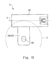
- the lengthwise direction F of the receptacle housing 22 coincides with the tangent direction of an imaginary circle C centered on the bolt hole 23 as viewed in the central axis direction as shown in Fig. 10 .
- the bolt hole 23 is deviated from an imaginary extension of the lengthwise direction F of the receptacle housing 22 as viewed in the central axis direction. That is, an aspect shown in Fig. 25 in which the bolt hole 23 is located on the imaginary extension of the lengthwise direction F of the receptacle housing 22 is excluded from the scope of this exemplary embodiment.
- the battery post 12 of the battery terminal unit 10 of the battery 4 is inserted into the bolt hole 23 of the receptacle contact 20 of the receptacle connector 5 and then the nut 7 is screwed on the battery post 12.
- the connecting cable 3 can be lead (or wired) from the front side of the battery 4.
- the receptacle housing 22 of the receptacle connector 5 faces the right side surface 8c of the battery main body 8 of the battery 4. Specifically, the receptacle housing 22 of the receptacle connector 5 is capable of coming into contact with the right side surface 8c of the battery main body 8 of the battery 4. Further, as shown in Fig. 3 , in the bolting process, the lengthwise direction F of the receptacle housing 22 of the receptacle connector 5 is roughly in parallel with the right side surface 8c of the battery main body 8 of the battery 4 as viewed in the central axis direction. Further, as shown in Fig.
- the lengthwise direction F of the receptacle housing 22 of the receptacle connector 5 is roughly in parallel with the upper surface 8a of the battery main body 8 of the battery 4 as viewed in the direction perpendicular to the right side surface 8c of the battery main body 8 of the battery 4.
- the plug connector 15 is inserted into the mating space S of the mating section 27 of the receptacle housing 22 of the receptacle connector 5.
- the locking claw 17 of the lance 16 of the plug housing 15b of the plug connector 15 is caught on the lance locking surface 27b of the mating section 27 of the receptacle housing 22 of the receptacle connector 5.
- the plug connector 15 is locked in the receptacle connector 5.
- the plug contact 15a of the plug connector 15 comes into contact with the tip part 41 of the receptacle contact 20 of the receptacle connector 5.
- the center conductor 14a of the connecting cable main body 14 of the connecting cable 3 is connected to the battery post 12 of the battery terminal unit 10 of the battery 4.
- the state in which "the receptacle housing 22 of the receptacle connector 5 is caught on the right side surface 8c of the battery main body 8 of the battery 4" means a state in which "the rotation of the receptacle housing 22 of the receptacle connector 5 is prevented halfway through the rotation by the right side surface 8c of the battery main body 8 of the battery 4 and hence cannot be advanced any further".
- the aforementioned torque T1 is received by the right press-fit holding surface 33a of the right press-fit holding part 33 of the housing main body 26 of the receptacle housing 22 and the left inner wall surface 36b of the housing main body 26 of the receptacle housing 22.
- the right bulging part 40a of the held part 40 of the receptacle contact 20 is immediately received by the right press-fit holding surface 33a of the right press-fit holding part 33 of the housing main body 26 of the receptacle housing 22.
- the interference part 44 of the receptacle contact 20 is received by the left inner wall surface 36b of the housing main body 26 of the receptacle housing 22. That is, as the interference part 44 of the receptacle contact 20 tries to move relative to the receptacle housing 22 in the bolting section counter-protruding direction, the interference part 44 is received by the left inner wall surface 36b of the housing main body 26 of the receptacle housing 22. Therefore, even when the torque T1 occurs, the clockwise rotation of the receptacle contact 20 with respect to the receptacle housing 22 is reliably prevented.
- the aforementioned counter-clockwise torque T2 is received by the left press-fit holding surface 34a of the left press-fit holding part 34 of the housing main body 26 of the receptacle housing 22 and the right inner wall surface 36a of the housing main body 26 of the receptacle housing 22.
- the left bulging part 40b of the held part 40 of the receptacle contact 20 is immediately received by the left press-fit holding surface 34a of the left press-fit holding part 34 of the housing main body 26 of the receptacle housing 22.
- the interference part 44 of the receptacle contact 20 is received by the right inner wall surface 36a of the housing main body 26 of the receptacle housing 22. That is, as the interference part 44 of the receptacle contact 20 tries to move relative to the receptacle housing 22 in the bolting section protruding direction, the interference part 44 is received by the right inner wall surface 36a of the housing main body 26 of the receptacle housing 22. Therefore, even when the torque T2 occurs, the counter-clockwise rotation of the receptacle contact 20 with respect to the receptacle housing 22 is reliably prevented.
- the receptacle connector 5 includes a displacement restricting mechanism E that prevents the base end part 42 of the receptacle contact 20 from moving relative to the receptacle housing 22 in the bolting section protruding direction or the bolting section counter-protruding direction.
- the displacement restricting mechanism E is formed by the interference part 44 and at least one of the right inner wall surface 36a and the left inner wall surface 36b.
- the first exemplary embodiment according to the present invention which is explained above, includes the following features.
- examples of the configuration for making the receptacle housing 22 hold the held part 40 include a configuration in which the held part 40 is press-fitted into the contact insertion hole 21 and a configuration using the lance 35.
- both configurations are used together.
- only the former configuration or the latter configuration may be employed instead.
- a plurality of protrusions 22b are formed on the side surface 22a on the bolting section protruding direction side of the receptacle housing 22 of the receptacle connector 5, these protrusions 22b can be omitted.
- the plurality of protrusions 22b are a part of the receptacle housing 22 of the receptacle connector 5.
- a second exemplary embodiment according to the present invention is explained hereinafter with reference to Fig. 26 .
- the following explanations are given with a particular emphasis on the differences between this exemplary embodiment and the above-described first exemplary embodiment, and duplicated explanations are omitted as appropriate.
- components of the second exemplary embodiment which are the same as or correspond to those of the first exemplary embodiment are assigned the same symbols as those assigned to the components of the first exemplary embodiment.
- the accommodated section 25 of the receptacle contact 20 includes a rear end part 60 in addition to the held part 40, the tip part 41, and the base end part 42.
- the rear end part 60 is a part that protrudes from the base end part 42 in the counter-inserting direction.
- a third exemplary embodiment according to the present invention is explained hereinafter with reference to Fig. 27 .
- the following explanations are given with a particular emphasis on the differences between this exemplary embodiment and the above-described first exemplary embodiment, and duplicated explanations are omitted as appropriate.
- components of the second exemplary embodiment which are the same as or correspond to those of the first exemplary embodiment are assigned the same symbols as those assigned to the components of the first exemplary embodiment.
- the bolting section 24 of the receptacle contact 20 is roughly perpendicular to the accommodated section 25.
- the thickness direction of the bolting section 24 of the receptacle contact 20 is roughly perpendicular to that of the accommodated section 25 of the receptacle contact 20.
- the thickness direction of the bolting section 24 of the receptacle contact 20 is roughly in parallel with the central axis direction.
- the thickness direction of the accommodated section 25 of the receptacle contact 20 is roughly in parallel with the crosswise direction.
- stacking rib 9 can be omitted in the above-described first to third exemplary embodiments.
Landscapes
- Chemical & Material Sciences (AREA)
- Chemical Kinetics & Catalysis (AREA)
- Electrochemistry (AREA)
- General Chemical & Material Sciences (AREA)
- Connection Of Batteries Or Terminals (AREA)
- Details Of Connecting Devices For Male And Female Coupling (AREA)
- Connections By Means Of Piercing Elements, Nuts, Or Screws (AREA)
Abstract
Description
- The present invention relates to an assembly.
- As this type of technique, as shown in
Fig. 28 of this application,Patent Literature 1 discloses a batteryterminal connection connector 104 for connectingelectric wires 100 to abattery post 103 of abattery terminal 102 of abattery 101. The batteryterminal connection connector 104 includes afemale connector housing 106 with abranch terminal 105 accommodated therein, and amale connector housing 108 for accommodating aconnection terminal 107 connected to an end of theelectric wires 100. In thebranch terminal 105, anattachment hole 109 through which thebattery post 103 can be inserted is formed. With this configuration, in order to attach thefemale connector housing 106 to thebattery terminal 102 of thebattery 101, thebattery post 103 is inserted through theattachment hole 109 of thebranch terminal 105 of thefemale connector housing 106 and then anut 110 is screwed on thebattery post 103. - Patent Literature 1: Japanese Unexamined Patent Application Publication No.
2001-256956 - However, in the above-described configuration of
Patent Literature 1, there is a risk that when thenut 110 is screwed on thebattery post 103, thefemale connector housing 106 could rotate with respect to thebattery 101. - An object of the invention of the present application is to provide a technique for preventing an electric connector from rotating relative to an object to be connected when the electric connector is screwed on the object to be connected.
- According to an aspect, the present invention provides an assembly including: an electric connector including a contact with a bolt hole for bolting formed therein, and a housing attached to the contact; and an object to be connected having a first surface on which the contact of the electric connector is attached by the bolting, and a second surface roughly perpendicular to the first surface, in which the housing of the electric connector is formed so as to extend in an elongated shape along a tangent direction of an imaginary circle centered on a central axis of the bolt hole of the contact of the electric connector as viewed in a central axis direction of the bolt hole, and is capable of coming into contact with the second surface of the object to be connected at the time of the bolting.
- The housing of the electric connector is capable of being disposed relative to the object to be connected so that a lengthwise direction of the housing of the electric connector is roughly in parallel with the second surface of the object to be connected at the time of the bolting as viewed in the central axis direction.
- The housing of the electric connector is capable of being disposed relative to the object to be connected so that a lengthwise direction of the housing of the electric connector is roughly in parallel with the first surface of the object to be connected at the time of the bolting as viewed in a direction perpendicular to the second surface of the object to be connected.
- The contact of the electric connector includes a first contact section in which the bolt hole is formed, and a second contact section connected to the first contact section, the second contact section extending along the lengthwise direction of the housing of the electric connector.
- A lengthwise direction of the first contact section is roughly perpendicular to that of the second contact section.
- The contact of the electric connector is formed in a roughly L-shape.
- The housing of the electric connector accommodates the second contact section.
- The first and second contact sections connect to each other in a halfway part in the lengthwise direction of the housing of the electric connector.
- A thickness direction of the first contact section is roughly in parallel with that of the second contact section.
- In the housing of the electric connector, a locking part for maintaining a connected state with a counterpart housing of a counterpart connector is formed.
- The object to be connected is a battery.
- The invention of the present application provides an advantageous effect that since the housing of the electric connector is effectively caught on the second surface of the object to be connected at the time of the bolting, rotation of the electric connector with respect to the object to be connected is prevented.
-
-
Fig. 1 is a perspective view of a battery unit (first exemplary embodiment); -
Fig. 2 is a front view of a battery assembly (first exemplary embodiment); -
Fig. 3 is a plan view of the battery assembly (first exemplary embodiment); -
Fig. 4 is a side view of the battery assembly (first exemplary embodiment); -
Fig. 5 is an exploded perspective view of the battery assembly (first exemplary embodiment); -
Fig. 6 is a perspective view of a battery (first exemplary embodiment); -
Fig. 7 is a perspective view of a part of a connecting cable (first exemplary embodiment); -
Fig. 8 is a perspective view of a receptacle connector (first exemplary embodiment); -
Fig. 9 is a perspective view of the receptacle connector as viewed from a different angle (first exemplary embodiment); -
Fig. 10 is a plan view of the receptacle connector (first exemplary embodiment); -
Fig. 11 is a partly-cut-out perspective view of the receptacle connector (first exemplary embodiment); -
Fig. 12 is an exploded perspective view of the receptacle connector (first exemplary embodiment); -
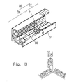
Fig. 13 is a partly-cut-out perspective view of a receptacle housing (first exemplary embodiment); -
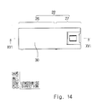
Fig. 14 is a plan view of the receptacle housing (first exemplary embodiment); -
Fig. 15 is a side view of the receptacle housing (first exemplary embodiment); -
Fig. 16 is a cross section taken along a line XVI-XVI ofFig. 14 (first exemplary embodiment); -
Fig. 17 is a cross section taken along a line XVII-XVII ofFig. 15 (first exemplary embodiment); -
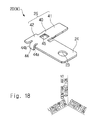
Fig. 18 is a perspective view of a receptacle contact (first exemplary embodiment); -
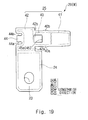
Fig. 19 is a plan view of the receptacle contact (first exemplary embodiment); -
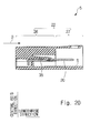
Fig. 20 is a cross section (corresponding toFig. 16 ) showing a state where the receptacle contact is attached to the receptacle housing (first exemplary embodiment); -
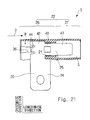
Fig. 21 is a cross section (corresponding toFig. 17 ) showing a state where the receptacle contact is attached to the receptacle housing (first exemplary embodiment); -
Fig. 22 is an enlarged view of a part A ofFig. 3 (first exemplary embodiment); -
Fig. 23 is a cross section (corresponding toFig. 21 ) of the receptacle connector and is for explaining workings of the receptacle connector (first exemplary embodiment); -
Fig. 24 is a cross section (corresponding toFig. 21 ) of the receptacle connector and is for explaining workings of the receptacle connector (first exemplary embodiment); -
Fig. 25 is a plan view of a battery assembly (comparative example); -
Fig. 26 is a perspective view of a receptacle contact (second exemplary embodiment); -
Fig. 27 is a perspective view of a receptacle contact (third exemplary embodiment); and -
Fig. 28 is a figure corresponding toFig. 1 ofPatent Literature 1. - A first exemplary embodiment according to the present invention is explained hereinafter with reference to
Figs. 1 to 24 . - As shown in
Fig. 1 , a battery unit 1 (assembled unit) includes a battery assembly 2 (assembly) and a connectingcable 3.Fig. 2 is a front view of thebattery assembly 2,Fig. 3 is a plan view of thebattery assembly 2, andFig. 4 is a side view of thebattery assembly 2. - As shown in
Fig. 5 , thebattery assembly 2 includes a battery 4 (object to be connected), a receptacle connector 5 (electric connector), abus bar 6, and a plurality ofnuts 7. - As shown in
Fig. 6 , thebattery 4 includes a batterymain body 8, astacking rib 9, and a pair ofbattery terminal units 10. The batterymain body 8 is formed in a roughly rectangular parallelepiped shape having anupper surface 8a (first surface), afront surface 8b, aright side surface 8c (second surface), aleft side surface 8d, and arear surface 8e. Therefore, theupper surface 8a is roughly perpendicular to theright side surface 8c. The stackingrib 9 is formed so as to protrude upward from the peripheral edge of theupper surface 8a and surround theupper surface 8a. The stackingrib 9 includes afront rib 9b corresponding to thefront surface 8b, aright side rib 9c corresponding to theright side surface 8c, a left side rib 9d corresponding to theleft side surface 8d, and arear rib 9e corresponding to therear surface 8e. The pair ofbattery terminal units 10 are formed on theupper surface 8a. Eachbattery terminal unit 10 is disposed in one of twocorner parts 8f, which are two of fourcorner parts 8f of theupper surface 8a located near thefront surface 8b. Eachbattery terminal unit 10 includes abattery terminal 11 and abattery post 12. In this exemplary embodiment, eachbattery post 12 is formed in a male screw shape and disposed so as to protrude upward from therespective battery terminal 11. In theright side rib 9c of the stackingrib 9, a battery terminal unit access slit 13 is formed so that a user can look in at thebattery terminal unit 10 as he/she looks at thebattery 4 in a direction perpendicular to theright side surface 8c. Similarly, another battery terminal unit access slit 13 is formed in the left side rib 9d of the stackingrib 9. Further, owing to the presence of theright side rib 9c, theright side surface 8c of the batterymain body 8 extends upward beyond theupper surface 8a. Similarly, owing to the presence of the left side rib 9d, theleft side surface 8d of the batterymain body 8 extends upward beyond theupper surface 8a. - As shown in
Fig. 7 , the connectingcable 3 includes a connecting cablemain body 14 and a plug connector 15 (counterpart connector) attached to an end of the connecting cablemain body 14. The connecting cablemain body 14 includes acenter conductor 14a and acover material 14b covering thecenter conductor 14a. Theplug connector 15 includes aplug contact 15a (counterpart contact) attached to thecenter conductor 14a, and aplug housing 15b that accommodates and holds theplug contact 15a. Alance 16 that is supported at both ends thereof is formed in theplug housing 15b. Thelance 16 includes a lockingclaw 17. - Next, the
receptacle connector 5 is explained with reference toFigs. 8 to 21 . - As shown in
Figs. 8 to 21 , thereceptacle connector 5 includes a receptacle contact 20 (contact) that is capable of coming into contact with theplug contact 15a of the plug connector 15 (seeFig. 7 ), and a receptacle housing 22 (housing) with acontact insertion hole 21 formed therein into which thereceptacle contact 20 is inserted. By inserting thereceptacle contact 20 into thecontact insertion hole 21, thereceptacle contact 20 is held by thereceptacle housing 22. - As shown in
Figs. 8 to 12 , thereceptacle housing 22 is formed in an elongated shape in this exemplary embodiment. Further, as shown inFig. 12 , thereceptacle contact 20 is formed in a roughly L-shape. That is, thereceptacle contact 20 includes a bolting section 24 (first contact section) with abolt hole 23 for bolting formed therein, and an accommodated section 25 (second contact section) that connects with thebolting section 24 and extends along a lengthwise direction of thereceptacle housing 22. A lengthwise direction of thebolting section 24 is roughly perpendicular to that of the accommodatedsection 25. As shown inFig. 12 , a direction in which thereceptacle contact 20 is inserted into thecontact insertion hole 21 of thereceptacle housing 22 is indicated by an inserting direction D in this exemplary embodiment. - A "lengthwise direction", a "central axis direction" and a "crosswise direction" are defined here. In principle, the lengthwise direction means the lengthwise direction of the
receptacle housing 22. The lengthwise direction includes the inserting direction D shown inFig. 12 and a counter-inserting direction that is a direction opposite to the inserting direction D. The central axis direction means a central axis direction of thebolt hole 23. The central axis direction includes an upward direction and a downward direction. The crosswise direction is perpendicular to both the lengthwise direction and the central axis direction. The crosswise direction includes a bolting section protruding direction, which is a direction from the accommodatedsection 25 toward thebolting section 24, and a bolting section counter-protruding direction, which is a direction from thebolting section 24 toward the accommodatedsection 25. - The
receptacle housing 22 of thereceptacle connector 5 is explained hereinafter with reference toFigs. 13 to 17 . Further, for the sake of convenience,Figs. 16 and17 show cross sections of thereceptacle housing 22 in a simplified manner. - As shown in
Figs. 13 to 15 , thereceptacle housing 22 has a roughly elongated rectangular parallelepiped external appearance. Thereceptacle housing 22 includes a housingmain body 26 and amating section 27. The housingmain body 26 adjoins the counter-inserting direction side of themating section 27. Themating section 27 adjoins the inserting direction side of the housingmain body 26. Thereceptacle housing 22 is formed in a roughly tubular shape. - As shown in
Figs. 16 and17 , the housingmain body 26 includes atop plate 30, abottom plate 31, aleft side plate 32, a right press-fit holding part 33, a left press-fit holding part 34, and alance 35. - The
top plate 30 and thebottom plate 31 are opposed to each other in the central axis direction. Thetop plate 30 is located above thebottom plate 31, and thebottom plate 31 is located below thetop plate 30. A gap g is formed between thetop plate 30 and thebottom plate 31. The gap g is slightly larger than the thickness of the receptacle contact 20 (see alsoFig. 12 ). - The
top plate 30 has alower surface 30a. Thelower surface 30a is a surface that faces thebottom plate 31. Thelance 35 is formed on thelower surface 30a. Thelance 35 is formed to prevent thereceptacle contact 20 from being removed. Thelance 35 is formed so as to extend from thelower surface 30a of thetop plate 30 in the inserting direction D in a cantilever shape. Alance claw 35a is formed at the free end of thelance 35. - The
bottom plate 31 has anupper surface 31a. Theupper surface 31a is a surface that faces thetop plate 30. An interferencepart insertion groove 36 is formed on theupper surface 31a. The interferencepart insertion groove 36 is formed on the counter-inserting direction side of theupper surface 31a. The upper side and the counter-inserting direction side of the interferencepart insertion groove 36 are opened. As shown inFig. 17 , the interferencepart insertion groove 36 is formed in such a manner that its width in the crosswise direction gradually decreases in the inserting direction D. Thebottom plate 31 has a rightinner wall surface 36a (inner wall surface, restricting part) and a leftinner wall surface 36b (inner wall surface, restricting part). The rightinner wall surface 36a is an inner wall surface that defines the bolting section protruding direction side of the interferencepart insertion groove 36. The leftinner wall surface 36b is an inner wall surface that defines the bolting section counter-protruding direction side of the interferencepart insertion groove 36. The rightinner wall surface 36a and the leftinner wall surface 36b are opposed to each other. Therefore, the gap between the rightinner wall surface 36a and leftinner wall surface 36b gradually decreases in the inserting direction D. - The
left side plate 32, the right press-fit holding part 33, and the left press-fit holding part 34 are all formed between thetop plate 30 and thebottom plate 31. - The
left side plate 32 and the left press-fit holding part 34 define the bolting section counter-protruding direction side of the gap g. Theleft side plate 32 adjoins the counter-inserting direction side of the left press-fit holding part 34. The left press-fit holding part 34 adjoins the inserting direction D side of theleft side plate 32. The right press-fit holding part 33 defines the bolting section protruding direction side of the gap g. The right press-fit holding part 33 and the left press-fit holding part 34 are opposed to each other in the crosswise direction. - The right press-
fit holding part 33 has a right press-fit holding surface 33a and a right contactinsertion restricting surface 33b. The right press-fit holding surface 33a is a surface that faces the left press-fit holding part 34. The right contactinsertion restricting surface 33b is a surface that faces in the counter-inserting direction. - The left press-
fit holding part 34 has a left press-fit holding surface 34a and a left contactinsertion restricting surface 34b. The left press-fit holding surface 34a is a surface that faces the right press-fit holding part 33. The left contactinsertion restricting surface 34b is a surface that faces in the counter-inserting direction. - In this exemplary embodiment, as indicated by broken lines in
Figs. 16 and17 , thecontact insertion hole 21 is formed by thelower surface 30a of thetop plate 30, theupper surface 31a of thebottom plate 31, the right press-fit holding surface 33a of the right press-fit holding part 33, and the left press-fit holding surface 34a of the left press-fit holding part 34. - As shown in
Fig. 16 , thelance claw 35a of thelance 35 is located inside thecontact insertion hole 21. - Further, as shown in
Figs. 16 and17 , a lightening 37 may be formed as appropriate. - The
mating section 27 is formed so as to protrude from the housingmain body 26 in the inserting direction D in a roughly rectangular-tube shape. As shown inFig. 16 , themating section 27 provides a mating space S in which theplug connector 15 is received. On a matingtop plate 27a of themating section 27, alance locking surface 27b (locking part) on which a lockingclaw 17 of thelance 16 of theplug housing 15b of theplug connector 15 shown inFig. 17 is caught is formed. - As shown in
Figs. 18 and19 , thereceptacle contact 20 is formed by a metal plate M having a somewhat large thickness. As described previously, thereceptacle contact 20 includes thebolting section 24 and the accommodatedsection 25. Specifically, thereceptacle contact 20 includes aninterference part 44 in addition to thebolting section 24 and the accommodatedsection 25. The accommodatedsection 25 includes a heldpart 40, atip part 41, and abase end part 42. Thebolting section 24 is roughly in parallel with the accommodatedsection 25 in the thickness direction. The thickness direction of each of thebolting section 24 and the accommodatedsection 25 is in parallel with the central axis direction. Further, the thickness direction of theinterference part 44 is perpendicular to that of thebase end part 42 and the like. The thickness direction of theinterference part 44 is in parallel with the lengthwise direction. Thebase end part 42, the heldpart 40, and thetip part 41 are arranged in this listed order in the inserting direction D. - The held
part 40 is a part that is accommodated in thecontact insertion hole 21 of the housingmain body 26 of thereceptacle housing 22 shown inFig. 17 and held by the housingmain body 26 of thereceptacle housing 22. As shown inFig. 19 , the heldpart 40 includes a right bulgingpart 40a bulging in the bolting section protruding direction and a left bulgingpart 40b bulging in the bolting section counter-protruding direction. The right bulgingpart 40a and the left bulgingpart 40b are formed near thetip part 41. Note that the width in the crosswise direction of thecontact insertion hole 21 between the right press-fit holding surface 33a of the right press-fit holding part 33 and the left press-fit holding surface 34a of the left press-fit holding part 34 shown inFig. 17 is adjusted so as to be slightly smaller than the width in the crosswise direction of the heldpart 40 including the right bulgingpart 40a and the left bulgingpart 40b shown inFig. 19 . - The
tip part 41 is a part that protrudes from the heldpart 40 in the inserting direction D and is capable of coming into contact with theplug contact 15a of the plug connector 15 (seeFig. 7 ). - The
base end part 42 is a part that protrudes from the heldpart 40 in the counter-inserting direction. Thebase end part 42 has a right shoulder surface 42a and aleft shoulder surface 42b. The right shoulder surface 42a is located on the bolting section protruding direction side relative to the heldpart 40 and faces in the inserting direction D. Theleft shoulder surface 42b is located on the bolting section counter-protruding direction side relative to the heldpart 40 and faces in the inserting direction D. - The
bolting section 24 is a part that protrudes from thebase end part 42 in the bolting section protruding direction. Abolt hole 23 for bolting is formed in thebolting section 24. - As shown in
Fig. 18 , theinterference part 44 is a part that protrudes from thebase end part 42. Theinterference part 44 protrudes in an obliquely downward direction with respect to thebase end part 42. In this exemplary embodiment, theinterference part 44 protrudes from thebase end part 42 in such a manner that the thickness direction of theinterference part 44 is roughly perpendicular to that of thebase end part 42. That is, theinterference part 44 is formed so as to protrude downward from thebase end part 42. Theinterference part 44 is disposed on the side opposite to the heldpart 40 across thebase end part 42. The thickness direction of theinterference part 44 is in parallel with the lengthwise direction. Theinterference part 44 has aright end surface 44a and aleft end surface 44b. Theright end surface 44a is an end surface that faces in the bolting section protruding direction. Theleft end surface 44b is an end surface that faces in the bolting section counter-protruding direction. - Further, a
lance locking hole 45 is formed in thereceptacle contact 20. Thereceptacle contact 20 has alance locking surface 45a that defines the inserting direction D side of thelance locking hole 45. Thelance locking surface 45a is located at roughly the center of the heldpart 40 in the lengthwise direction. In other words, thelance locking surface 45a, on which thelance claw 35a of thelance 35 is caught, is formed in the heldpart 40 of thereceptacle contact 20. - Next, a method for assembling the
receptacle connector 5 is explained with reference toFigs. 20 and21 . - In order to assemble the
receptacle connector 5, as shown inFig. 21 , thereceptacle contact 20 is firmly inserted into the gap g of thereceptacle housing 22. - As a result, the right shoulder surface 42a and the
left shoulder surface 42b of thebase end part 42 of thereceptacle contact 20 shown inFig. 19 are brought into contact with the right contactinsertion restricting surface 33b of the right press-fit holding part 33 and the left contactinsertion restricting surface 34b of the left press-fit holding part 34, respectively, of thereceptacle housing 22 shown inFig. 17 , thus preventing thereceptacle contact 20 from being inserted in the gap g of thereceptacle housing 22 any further. - In the state shown in
Fig. 21 , the heldpart 40 of thereceptacle contact 20 is press-fitted into thecontact insertion hole 21 of thereceptacle housing 22, so that the heldpart 40 is held by thereceptacle housing 22. Specifically, by press-fitting the heldpart 40 of thereceptacle contact 20 into thecontact insertion hole 21, the heldpart 40 is caught in thereceptacle housing 22 in the crosswise direction and, consequently, is held by thereceptacle housing 22. More specifically, in the state shown inFig. 21 , theright bulging part 40a of the heldpart 40 of thereceptacle contact 20 shown inFig. 19 bites into the right press-fit holding surface 33a of the right press-fit holding part 33 of the housingmain body 26 of thereceptacle housing 22 shown inFig. 17 . Similarly, theleft bulging part 40b of the heldpart 40 of thereceptacle contact 20 shown inFig. 19 bites into the left press-fit holding surface 34a of the left press-fit holding part 34 of the housingmain body 26 of thereceptacle housing 22 shown inFig. 17 . In this manner, as the heldpart 40 of thereceptacle contact 20 is press-fitted into thecontact insertion hole 21 of thereceptacle housing 22, the heldpart 40 of thereceptacle contact 20 is restrained in thereceptacle housing 22 in the lengthwise direction and in the crosswise direction. - Further, in the state shown in
Fig. 21 , theinterference part 44 of thereceptacle contact 20 is press-fitted into the interferencepart insertion groove 36 of thereceptacle housing 22. More specifically, theright end surface 44a of theinterference part 44 of thereceptacle contact 20 shown inFig. 19 bites into the rightinner wall surface 36a of the housingmain body 26 of thereceptacle housing 22 shown inFig. 17 . Similarly, theleft end surface 44b of theinterference part 44 of thereceptacle contact 20 shown inFig. 19 bites into the leftinner wall surface 36b of the housingmain body 26 of thereceptacle housing 22 shown inFig. 17 . In this manner, as theinterference part 44 of thereceptacle contact 20 is press-fitted into the interferencepart insertion groove 36 of thereceptacle housing 22, theinterference part 44 of thereceptacle contact 20 is restrained in thereceptacle housing 22 in the lengthwise direction and in the crosswise direction. - Further, in the state shown in
Fig. 20 , thereceptacle contact 20 is locked by thelance 35 of the housingmain body 26 of thereceptacle housing 22. More specifically, thelance claw 35a of thelance 35 of the housingmain body 26 of thereceptacle housing 22 shown inFig. 16 has penetrated into thelance locking hole 45 of thereceptacle contact 20 shown inFig. 19 . As a result, thelance claw 35a of thelance 35 of the housingmain body 26 of thereceptacle housing 22 shown inFig. 16 faces thelance locking surface 45a of thelance locking hole 45 of thereceptacle contact 20 shown inFig. 19 . In this manner, since thelance claw 35a of thelance 35 of the housingmain body 26 of thereceptacle housing 22 is caught on thelance locking surface 45a of thelance locking hole 45 of thereceptacle contact 20, the heldpart 40 of thereceptacle contact 20 is held by thereceptacle housing 22. This prevents the problem that thereceptacle housing 22 could be pulled out in the inserting direction D from thereceptacle contact 20 fixed to thebattery 4 when, for example, the connectingcable 3 is accidentally pulled. - Further, in the state shown in
Fig. 20 , thetip part 41 of thereceptacle contact 20 is located inside the mating space S of themating section 27 of thereceptacle housing 22 as shown inFig. 21 . Thebolting section 24 of thereceptacle contact 20 is located on the bolting section protruding direction side relative to thereceptacle housing 22. - Further, in the state shown in
Fig. 20 , the lengthwise direction F of thereceptacle housing 22 coincides with the tangent direction of an imaginary circle C centered on thebolt hole 23 as viewed in the central axis direction as shown inFig. 10 . In other words, thebolt hole 23 is deviated from an imaginary extension of the lengthwise direction F of thereceptacle housing 22 as viewed in the central axis direction. That is, an aspect shown inFig. 25 in which thebolt hole 23 is located on the imaginary extension of the lengthwise direction F of thereceptacle housing 22 is excluded from the scope of this exemplary embodiment. - Next, usage of the
receptacle connector 5 and its workings are explained with reference toFigs. 1 to 5 andFigs. 22 to 24 . - To attach the
receptacle connector 5 to thebattery terminal unit 10 of thebattery 4 shown inFig. 6 , as shown inFig. 5 , thebattery post 12 of thebattery terminal unit 10 of thebattery 4 is inserted into thebolt hole 23 of thereceptacle contact 20 of thereceptacle connector 5 and then thenut 7 is screwed on thebattery post 12. In this way, the connectingcable 3 can be lead (or wired) from the front side of thebattery 4. - In this bolting process, in this exemplary embodiment, as shown in
Figs. 2 and3 , thereceptacle housing 22 of thereceptacle connector 5 faces theright side surface 8c of the batterymain body 8 of thebattery 4. Specifically, thereceptacle housing 22 of thereceptacle connector 5 is capable of coming into contact with theright side surface 8c of the batterymain body 8 of thebattery 4. Further, as shown inFig. 3 , in the bolting process, the lengthwise direction F of thereceptacle housing 22 of thereceptacle connector 5 is roughly in parallel with theright side surface 8c of the batterymain body 8 of thebattery 4 as viewed in the central axis direction. Further, as shown inFig. 4 , in the bolting process, the lengthwise direction F of thereceptacle housing 22 of thereceptacle connector 5 is roughly in parallel with theupper surface 8a of the batterymain body 8 of thebattery 4 as viewed in the direction perpendicular to theright side surface 8c of the batterymain body 8 of thebattery 4. - Further, to mate the
plug connector 15 shown inFig. 7 with thereceptacle connector 5 shown inFig. 21 , theplug connector 15 is inserted into the mating space S of themating section 27 of thereceptacle housing 22 of thereceptacle connector 5. As a result, the lockingclaw 17 of thelance 16 of theplug housing 15b of theplug connector 15 is caught on thelance locking surface 27b of themating section 27 of thereceptacle housing 22 of thereceptacle connector 5. By this action, theplug connector 15 is locked in thereceptacle connector 5. By mating theplug connector 15 with thereceptacle connector 5 as described above, theplug contact 15a of theplug connector 15 comes into contact with thetip part 41 of thereceptacle contact 20 of thereceptacle connector 5. As a result, thecenter conductor 14a of the connecting cablemain body 14 of the connectingcable 3 is connected to thebattery post 12 of thebattery terminal unit 10 of thebattery 4. - Note that as shown in
Fig. 22 , when thenut 7 is screwed on thebattery post 12 of thebattery terminal unit 10 of thebattery 4, a clockwise torque T1 occurs in thereceptacle contact 20 of thereceptacle connector 5. Therefore, thereceptacle connector 5 tries to rotate in the clockwise direction. However, since thereceptacle housing 22 of thereceptacle connector 5 is caught on theright side surface 8c of the batterymain body 8 of thebattery 4, the clockwise rotation of thereceptacle connector 5 is restricted. Note that the state in which "thereceptacle housing 22 of thereceptacle connector 5 is caught on theright side surface 8c of the batterymain body 8 of thebattery 4" means a state in which "the rotation of thereceptacle housing 22 of thereceptacle connector 5 is prevented halfway through the rotation by theright side surface 8c of the batterymain body 8 of thebattery 4 and hence cannot be advanced any further". - Further, inside the
receptacle connector 5, as shown inFig. 23 , the aforementioned torque T1 is received by the right press-fit holding surface 33a of the right press-fit holding part 33 of the housingmain body 26 of thereceptacle housing 22 and the leftinner wall surface 36b of the housingmain body 26 of thereceptacle housing 22. Specifically, when the torque T1 occurs, theright bulging part 40a of the heldpart 40 of thereceptacle contact 20 is immediately received by the right press-fit holding surface 33a of the right press-fit holding part 33 of the housingmain body 26 of thereceptacle housing 22. At the same time, theinterference part 44 of thereceptacle contact 20 is received by the leftinner wall surface 36b of the housingmain body 26 of thereceptacle housing 22. That is, as theinterference part 44 of thereceptacle contact 20 tries to move relative to thereceptacle housing 22 in the bolting section counter-protruding direction, theinterference part 44 is received by the leftinner wall surface 36b of the housingmain body 26 of thereceptacle housing 22. Therefore, even when the torque T1 occurs, the clockwise rotation of thereceptacle contact 20 with respect to thereceptacle housing 22 is reliably prevented. - On the other hand, when the
nut 7 is loosened, a counter-clockwise torque occurs in thereceptacle contact 20 of thereceptacle connector 5. Therefore, thereceptacle connector 5 tries to rotate in the counter-clockwise direction. However, since thereceptacle housing 22 of thereceptacle connector 5 is caught on theright side surface 8c of the batterymain body 8 of thebattery 4, the counter-clockwise rotation of thereceptacle connector 5 is restricted. - Further, inside the
receptacle connector 5, as shown inFig. 24 , the aforementioned counter-clockwise torque T2 is received by the left press-fit holding surface 34a of the left press-fit holding part 34 of the housingmain body 26 of thereceptacle housing 22 and the rightinner wall surface 36a of the housingmain body 26 of thereceptacle housing 22. Specifically, when the torque T2 occurs, theleft bulging part 40b of the heldpart 40 of thereceptacle contact 20 is immediately received by the left press-fit holding surface 34a of the left press-fit holding part 34 of the housingmain body 26 of thereceptacle housing 22. At the same time, theinterference part 44 of thereceptacle contact 20 is received by the rightinner wall surface 36a of the housingmain body 26 of thereceptacle housing 22. That is, as theinterference part 44 of thereceptacle contact 20 tries to move relative to thereceptacle housing 22 in the bolting section protruding direction, theinterference part 44 is received by the rightinner wall surface 36a of the housingmain body 26 of thereceptacle housing 22. Therefore, even when the torque T2 occurs, the counter-clockwise rotation of thereceptacle contact 20 with respect to thereceptacle housing 22 is reliably prevented. - In this exemplary embodiment, as shown in
Figs. 23 and24 , thereceptacle connector 5 includes a displacement restricting mechanism E that prevents thebase end part 42 of thereceptacle contact 20 from moving relative to thereceptacle housing 22 in the bolting section protruding direction or the bolting section counter-protruding direction. Further, the displacement restricting mechanism E is formed by theinterference part 44 and at least one of the rightinner wall surface 36a and the leftinner wall surface 36b. - The first exemplary embodiment according to the present invention, which is explained above, includes the following features.
- (1) A battery assembly 2 (assembly) includes: a receptacle connector 5 (electric connector) including a receptacle contact 20 (contact) with a
bolt hole 23 for bolting formed therein, and areceptacle housing 22 attached to thereceptacle contact 20; and a battery 4 (object to be connected) having anupper surface 8a (first surface) on which thereceptacle contact 20 of thereceptacle connector 5 is attached by the bolting, and aright side surface 8c (second surface) roughly perpendicular to theupper surface 8a. Thereceptacle housing 22 of thereceptacle connector 5 is formed so as to extend in an elongated shape along the tangent direction of an imaginary circle C centered on the central axis of thebolt hole 23 of thereceptacle contact 20 of thereceptacle connector 5 as viewed in the central axis direction of thebolt hole 23. Theside surface 22a on the bolting section protruding direction side of thereceptacle housing 22 of thereceptacle connector 5 is capable of coming into contact with theright side surface 8c of thebattery 4 at the time of the bolting. The above-described configuration provides an advantageous effect that since thereceptacle housing 22 of thereceptacle connector 5 is effectively caught on theright side surface 8c of thebattery 4 at the time of the bolting, the rotation of thereceptacle connector 5 with respect to thebattery 4 is prevented. - (2) Further, as shown in
Fig. 3 , thereceptacle housing 22 of thereceptacle connector 5 is capable of being disposed relative to thebattery 4 so that the lengthwise direction F of thereceptacle housing 22 of thereceptacle connector 5 is roughly in parallel with theright side surface 8c of thebattery 4 at the time of the bolting as viewed in the central axis direction. The above-described configuration provides an advantageous effect that since thereceptacle housing 22 of thereceptacle connector 5 is caught on theright side surface 8c of thebattery 4 more effectively at the time of the bolting, the rotation of thereceptacle connector 5 with respect to thebattery 4 is more reliably prevented. - (3) Further, as shown in
Fig. 4 , thereceptacle housing 22 of thereceptacle connector 5 is capable of being disposed relative to thebattery 4 so that the lengthwise direction F of thereceptacle housing 22 of thereceptacle connector 5 is roughly in parallel with theupper surface 8a of thebattery 4 at the time of the bolting as viewed in the direction perpendicular to theright side surface 8c. The above-described configuration provides an advantageous effect that since thereceptacle housing 22 of thereceptacle connector 5 is caught on theright side surface 8c of thebattery 4 more effectively at the time of the bolting, the rotation of thereceptacle connector 5 with respect to thebattery 4 is more reliably prevented. - (4) Further, as shown in
Fig. 19 , thereceptacle contact 20 of thereceptacle connector 5 includes a bolting section 24 (first contact section) in which thebolt hole 23 is formed, and an accommodated section 25 (second contact section) that connects with thebolting section 24 and extends along the lengthwise direction F of thereceptacle housing 22 of thereceptacle connector 5. - (5) Further, the
bolting section 24 is roughly perpendicular to the accommodatedsection 25. Specifically, the lengthwise direction of thebolting section 24 is roughly perpendicular to that of the accommodatedsection 25. - (6) Further, the
receptacle contact 20 of thereceptacle connector 5 is formed in a roughly L-shape. - (7) Further, as shown in
Fig. 21 , thereceptacle housing 22 of thereceptacle connector 5 accommodates the accommodatedsection 25. - (8) Further, the
bolting section 24 and the accommodatedsection 25 connect to each other in a halfway part in the lengthwise direction F of thereceptacle housing 22 of thereceptacle connector 5. - (9) Further, the thickness direction of the
bolting section 24 is roughly in parallel with that of the accommodatedsection 25. - (10) Further, as shown in
Fig. 16 , alance locking surface 27b (locking part) for maintaining the connected state with aplug housing 15b (counterpart housing) of a plug connector 15 (counterpart connector) is formed in thereceptacle housing 22 of thereceptacle connector 5. - (11) Examples of the object to be connected include a
battery 4. - Note that examples of the configuration for making the
receptacle housing 22 hold the heldpart 40 include a configuration in which the heldpart 40 is press-fitted into thecontact insertion hole 21 and a configuration using thelance 35. In the above-described first exemplary embodiment, both configurations are used together. However, only the former configuration or the latter configuration may be employed instead. - Further, although, as shown in
Fig. 8 , a plurality ofprotrusions 22b are formed on theside surface 22a on the bolting section protruding direction side of thereceptacle housing 22 of thereceptacle connector 5, theseprotrusions 22b can be omitted. The plurality ofprotrusions 22b are a part of thereceptacle housing 22 of thereceptacle connector 5. - Next, a second exemplary embodiment according to the present invention is explained hereinafter with reference to
Fig. 26 . The following explanations are given with a particular emphasis on the differences between this exemplary embodiment and the above-described first exemplary embodiment, and duplicated explanations are omitted as appropriate. Further, in principle, components of the second exemplary embodiment which are the same as or correspond to those of the first exemplary embodiment are assigned the same symbols as those assigned to the components of the first exemplary embodiment. - In this exemplary embodiment, the accommodated
section 25 of thereceptacle contact 20 includes arear end part 60 in addition to the heldpart 40, thetip part 41, and thebase end part 42. Therear end part 60 is a part that protrudes from thebase end part 42 in the counter-inserting direction. - Next, a third exemplary embodiment according to the present invention is explained hereinafter with reference to
Fig. 27 . The following explanations are given with a particular emphasis on the differences between this exemplary embodiment and the above-described first exemplary embodiment, and duplicated explanations are omitted as appropriate. Further, in principle, components of the second exemplary embodiment which are the same as or correspond to those of the first exemplary embodiment are assigned the same symbols as those assigned to the components of the first exemplary embodiment. - In this exemplary embodiment, the
bolting section 24 of thereceptacle contact 20 is roughly perpendicular to the accommodatedsection 25. Specifically, the thickness direction of thebolting section 24 of thereceptacle contact 20 is roughly perpendicular to that of the accommodatedsection 25 of thereceptacle contact 20. The thickness direction of thebolting section 24 of thereceptacle contact 20 is roughly in parallel with the central axis direction. The thickness direction of the accommodatedsection 25 of thereceptacle contact 20 is roughly in parallel with the crosswise direction. - Note that the stacking
rib 9 can be omitted in the above-described first to third exemplary embodiments. - This application is based upon and claims the benefit of priority from Japanese patent application No.
2012-220109, filed on October 2, 2012 -
- 1
- BATTERY UNIT
- 2
- BATTERY ASSEMBLY (ASSEMBLY)
- 3
- CONNECTING CABLE
- 4
- BATTERY (OBJECT TO BE CONNECTED)
- 5
- RECEPTACLE CONNECTOR (ELECTRIC CONNECTOR)
- 6
- BUS BAR
- 7
- NUT
- 8
- BATTERY MAIN BODY
- 8a
- UPPER SURFACE (FIRST SURFACE)
- 8b
- FRONT SURFACE
- 8c
- RIGHT SIDE SURFACE (SECOND SURFACE)
- 8d
- LEFT SIDE SURFACE
- 8e
- REAR SURFACE
- 8f
- CORNER PART
- 9
- STACKING RIB
- 9b
- FRONT RIB
- 9c
- RIGHT SIDE RIB
- 9d
- LEFT SIDE RIB
- 9e
- REAR RIB
- 10
- BATTERY TERMINAL UNIT
- 11
- BATTERY TERMINAL
- 12
- BATTERY POST
- 13
- BATTERY TERMINAL UNIT ACCESS SLIT
- 14
- CONNECTING CABLE MAIN BODY
- 14a
- CENTER CONDUCTOR
- 14b
- COVER MATERIAL
- 15
- PLUG CONNECTOR (COUNTERPART CONNECTOR)
- 15a
- PLUG CONTACT
- 15b
- PLUG HOUSING (COUNTERPART HOUSING)
- 16
- LANCE
- 17
- LOCKING CLAW
- 20
- RECEPTACLE CONTACT (CONTACT)
- 21
- CONTACT INSERTION HOLE
- 22
- RECEPTACLE HOUSING
- 22a
- SIDE SURFACE
- 22b
- PROTRUSION
- 23
- BOLT HOLE
- 24
- BOLTING SECTION (FIRST CONTACT SECTION)
- 25
- ACCOMMODATED SECTION (SECOND CONTACT SECTION)
- 26
- HOUSING MAIN BODY
- 27
- MATING SECTION
- 27a
- MATING TOP PLATE
- 27b
- LANCE LOCKING SURFACE (LOCKING PART)
- 30
- TOP PLATE
- 30a
- LOWER SURFACE
- 31
- BOTTOM PLATE
- 31a
- UPPER SURFACE
- 32
- LEFT SIDE PLATE
- 33
- RIGHT PRESS-FIT HOLDING PART
- 33a
- RIGHT PRESS-FIT HOLDING SURFACE
- 33b
- RIGHT CONTACT INSERTION RESTRICTING SURFACE
- 34
- LEFT PRESS-FIT HOLDING PART
- 34a
- LEFT PRESS-FIT HOLDING SURFACE
- 34b
- LEFT CONTACT INSERTION RESTRICTING SURFACE
- 35
- LANCE
- 35a
- LANCE CLAW
- 36
- INTERFERENCE PART INSERTION GROOVE
- 36a
- RIGHT INNER WALL SURFACE
- 36b
- LEFT INNER WALL SURFACE
- 37
- LIGHTENING
- 40
- HELD PART
- 40a
- RIGHT BULGING PART
- 40b
- LEFT BULGING PART
- 41
- TIP PART
- 42
- BASE END PART
- 42a
- RIGHT SHOULDER SURFACE
- 42b
- LEFT SHOULDER SURFACE
- 44
- INTERFERENCE PART
- 44a
- RIGHT END SURFACE
- 44b
- LEFT END SURFACE
- 45
- LANCE LOCKING HOLE
- 45a
- LANCE LOCKING SURFACE
- 60
- REAR END PART
- g
- GAP
- D
- INSERTING DIRECTION
- F
- LENGTHWISE DIRECTION
- M
- METAL PLATE
- S
- MATING SPACE
- T1
- TORQUE
- T2
- TORQUE
- E
- DISPLACEMENT RESTRICTING MECHANISM
Claims (11)
- An assembly comprising:an electric connector comprising a contact with a bolt hole for bolting formed therein, and a housing attached to the contact; andan object to be connected having a first surface on which the contact of the electric connector is attached by the bolting, and a second surface roughly perpendicular to the first surface, whereinthe housing of the electric connector is formed so as to extend in an elongated shape along a tangent direction of an imaginary circle centered on a central axis of the bolt hole of the contact of the electric connector as viewed in a central axis direction of the bolt hole, and is capable of coming into contact with the second surface of the object to be connected at the time of the bolting.
- The assembly according to Claim 1, wherein the housing of the electric connector is capable of being disposed relative to the object to be connected so that a lengthwise direction of the housing of the electric connector is roughly in parallel with the second surface of the object to be connected at the time of the bolting as viewed in the central axis direction.
- The assembly according to Claim 1 or 2, wherein the housing of the electric connector is capable of being disposed relative to the object to be connected so that a lengthwise direction of the housing of the electric connector is roughly in parallel with the first surface of the object to be connected at the time of the bolting as viewed in a direction perpendicular to the second surface of the object to be connected.
- The assembly according to any one of Claims 1 to 3, wherein the contact of the electric connector comprises a first contact section in which the bolt hole is formed, and a second contact section connected to the first contact section, the second contact section extending along the lengthwise direction of the housing of the electric connector.
- The assembly according to Claim 4, wherein a lengthwise direction of the first contact section is roughly perpendicular to that of the second contact section.
- The assembly according to Claim 5, wherein the contact of the electric connector is formed in a roughly L-shape.
- The assembly according to Claim 6, wherein the housing of the electric connector accommodates the second contact section.
- The assembly according to Claim 7, wherein the first and second contact sections connect to each other in a halfway part in the lengthwise direction of the housing of the electric connector.
- The assembly according to any one of Claims 4 to 8, wherein a thickness direction of the first contact section is roughly in parallel with that of the second contact section.
- The assembly according to any one of Claims 1 to 9, wherein in the housing of the electric connector, a locking part for maintaining a connected state with a counterpart housing of a counterpart connector is formed.
- The assembly according to any one of Claims 1 to 10, wherein the object to be connected is a battery.
Applications Claiming Priority (2)
| Application Number | Priority Date | Filing Date | Title |
|---|---|---|---|
| JP2012220109A JP5480947B2 (en) | 2012-10-02 | 2012-10-02 | Assembly |
| PCT/JP2013/003855 WO2014054203A1 (en) | 2012-10-02 | 2013-06-20 | Assembly |
Publications (3)
| Publication Number | Publication Date |
|---|---|
| EP2905847A1 true EP2905847A1 (en) | 2015-08-12 |
| EP2905847A4 EP2905847A4 (en) | 2016-03-30 |
| EP2905847B1 EP2905847B1 (en) | 2018-08-08 |
Family
ID=50434554
Family Applications (1)
| Application Number | Title | Priority Date | Filing Date |
|---|---|---|---|
| EP13843879.1A Active EP2905847B1 (en) | 2012-10-02 | 2013-06-20 | Assembly |
Country Status (5)
| Country | Link |
|---|---|
| US (1) | US9437942B2 (en) |
| EP (1) | EP2905847B1 (en) |
| JP (1) | JP5480947B2 (en) |
| CN (1) | CN104685731B (en) |
| WO (1) | WO2014054203A1 (en) |
Cited By (1)
| Publication number | Priority date | Publication date | Assignee | Title |
|---|---|---|---|---|
| EP3109926A1 (en) * | 2015-06-22 | 2016-12-28 | Samsung SDI Co., Ltd. | Rechargeable battery and rechargeable battery module |
Families Citing this family (10)
| Publication number | Priority date | Publication date | Assignee | Title |
|---|---|---|---|---|
| JP5352723B1 (en) * | 2012-09-05 | 2013-11-27 | 日本航空電子工業株式会社 | Electrical connector |
| JP6135246B2 (en) * | 2013-03-29 | 2017-05-31 | 株式会社Gsユアサ | Power storage device |
| TWM533365U (en) * | 2016-08-25 | 2016-12-01 | Formosa Electronic Ind Inc | Plug-in connection structure of stacked energy-storage battery module |
| CN110419125A (en) * | 2017-03-10 | 2019-11-05 | 远景Aesc能源元器件有限公司 | Battery pack manufacturing method and battery pack |
| US10720619B2 (en) * | 2017-10-16 | 2020-07-21 | Ford Global Technologies, Llc | Array frame mounting inserts for securing battery assemblies |
| JP7140725B2 (en) * | 2019-07-31 | 2022-09-21 | 本田技研工業株式会社 | power supply |
| US12476395B2 (en) * | 2022-05-01 | 2025-11-18 | Cytherean Mandelbrot LLC | Jump starting systems with electrical jumper plugs |
| KR20240060271A (en) * | 2022-10-28 | 2024-05-08 | 주식회사 엘지에너지솔루션 | Secondary battery having improved terminal structure |
| JP7849329B2 (en) * | 2023-05-08 | 2026-04-21 | 矢崎総業株式会社 | Device equipped with a battery terminal cover |
| JP2025019718A (en) * | 2023-07-28 | 2025-02-07 | 日本航空電子工業株式会社 | Angled Connector |
Family Cites Families (22)
| Publication number | Priority date | Publication date | Assignee | Title |
|---|---|---|---|---|
| JP3286474B2 (en) * | 1994-09-29 | 2002-05-27 | 三洋電機株式会社 | Electric equipment with built-in battery |
| US5645448A (en) | 1995-10-16 | 1997-07-08 | Yazaki Corporation | Battery connecting module with fuse mounting |
| US5897392A (en) * | 1997-03-26 | 1999-04-27 | Yazaki Corporation | Wire retaining clip |
| US6001506A (en) * | 1997-07-30 | 1999-12-14 | Concorde Battery Corporation | Terminal post assembly for lead acid batteries |
| JP3526240B2 (en) * | 1999-05-20 | 2004-05-10 | 矢崎総業株式会社 | Terminal connection structure of electrical junction box |
| JP3622897B2 (en) * | 2000-03-14 | 2005-02-23 | 矢崎総業株式会社 | Battery terminal connector |
| JP3673456B2 (en) * | 2000-08-21 | 2005-07-20 | アルプス電気株式会社 | Battery holder |
| US20030039882A1 (en) * | 2001-01-26 | 2003-02-27 | Wruck William J. | Reverse polarity termination adaptor |
| US6695628B2 (en) * | 2002-05-17 | 2004-02-24 | Hon Hai Precision Ind. Co., Ltd. | Battery connector |
| JP3704130B2 (en) * | 2003-03-28 | 2005-10-05 | 京セラ株式会社 | Battery and battery manufacturing method |
| EP1469564B1 (en) * | 2003-04-17 | 2012-12-05 | Autoliv Development AB | Pyrotechnical battery terminal |
| TWM256620U (en) * | 2004-02-10 | 2005-02-01 | Hon Hai Prec Ind Co Ltd | Battery connector |
| US20060003627A1 (en) * | 2004-07-01 | 2006-01-05 | Erik Freitag | Fused battery terminal connector |
| CN2819483Y (en) * | 2005-04-15 | 2006-09-20 | 金达时发展有限公司 | Combinable connecting frame for thin-plate lithium battery |
| US8147280B2 (en) | 2007-06-04 | 2012-04-03 | Lear Corporation | Battery post connector |
| US7663466B1 (en) * | 2007-09-21 | 2010-02-16 | Yazaki North America, Inc. | Corner-mounted battery fuse |
| JP5487405B2 (en) * | 2008-10-24 | 2014-05-07 | 日本圧着端子製造株式会社 | connector |
| JP5813302B2 (en) * | 2009-09-07 | 2015-11-17 | 矢崎総業株式会社 | Bus bar module and power supply device including the bus bar module |
| US7794263B1 (en) * | 2009-09-30 | 2010-09-14 | Apple Inc. | Connector receptacle housings having reduced-wear finger contacts and reduced seam visibility |
| US20110293987A1 (en) * | 2010-05-25 | 2011-12-01 | Steven Tartaglia | Battery terminal connection system |
| KR101199179B1 (en) * | 2010-06-09 | 2012-11-07 | 삼성에스디아이 주식회사 | Connecting structure of battery stack |
| US9440601B2 (en) * | 2013-09-06 | 2016-09-13 | Johnson Controls Technology Company | System for providing voltage measurements of battery cells to a PCB within a battery module |
-
2012
- 2012-10-02 JP JP2012220109A patent/JP5480947B2/en active Active
-
2013
- 2013-06-20 CN CN201380049431.0A patent/CN104685731B/en active Active
- 2013-06-20 WO PCT/JP2013/003855 patent/WO2014054203A1/en not_active Ceased
- 2013-06-20 EP EP13843879.1A patent/EP2905847B1/en active Active
- 2013-06-20 US US14/432,393 patent/US9437942B2/en active Active
Cited By (1)
| Publication number | Priority date | Publication date | Assignee | Title |
|---|---|---|---|---|
| EP3109926A1 (en) * | 2015-06-22 | 2016-12-28 | Samsung SDI Co., Ltd. | Rechargeable battery and rechargeable battery module |
Also Published As
| Publication number | Publication date |
|---|---|
| CN104685731B (en) | 2017-07-14 |
| JP5480947B2 (en) | 2014-04-23 |
| US9437942B2 (en) | 2016-09-06 |
| EP2905847A4 (en) | 2016-03-30 |
| CN104685731A (en) | 2015-06-03 |
| US20150280336A1 (en) | 2015-10-01 |
| EP2905847B1 (en) | 2018-08-08 |
| JP2014072167A (en) | 2014-04-21 |
| WO2014054203A1 (en) | 2014-04-10 |
Similar Documents
| Publication | Publication Date | Title |
|---|---|---|
| EP2905847B1 (en) | Assembly | |
| US7059892B1 (en) | Electrical connector and backshell | |
| JP5534350B2 (en) | Connector device | |
| US8267722B2 (en) | Cable connector assembly having improved grounding member | |
| EP0649191A1 (en) | Shielded connector with hermaphroditic shell | |
| US8512069B2 (en) | Flat plug electrical connector | |
| US8562376B2 (en) | Cable connector assembly having a capacitor connected with one connector and a metallic shell | |
| CN102332645A (en) | Ground connection and wiring harness | |
| RU2722920C1 (en) | Wire-to-wire connector with a jumper | |
| CN107210565A (en) | Shielded connector | |
| SG181191A1 (en) | A gasket for an emi connector | |
| EP2161791A2 (en) | Cable connector | |
| US9368919B2 (en) | Plug connector comprising a protective conductor bridge | |
| JP5341532B2 (en) | A pair of erroneous mating prevention keys and an electrical connector using the keys | |
| US10505309B2 (en) | Electrical device having a seal assembly | |
| US6089916A (en) | Cable assembly connector | |
| US20190229461A1 (en) | Power connector with terminal | |
| US9362649B2 (en) | Electric connector | |
| CN101237093A (en) | Electric connector | |
| JP5303348B2 (en) | Lock structure and electrical connector using the lock structure | |
| JP2010257725A (en) | connector | |
| US8851922B2 (en) | Electrical connector device and connector used in the electrical connector device | |
| JP2011181199A (en) | Mating structure and electrical connector using the same | |
| US11557855B2 (en) | Low profile angled connector | |
| JP3060508U (en) | Right angle connector |
Legal Events
| Date | Code | Title | Description |
|---|---|---|---|
| PUAI | Public reference made under article 153(3) epc to a published international application that has entered the european phase |
Free format text: ORIGINAL CODE: 0009012 |
|
| 17P | Request for examination filed |
Effective date: 20150327 |
|
| AK | Designated contracting states |
Kind code of ref document: A1 Designated state(s): AL AT BE BG CH CY CZ DE DK EE ES FI FR GB GR HR HU IE IS IT LI LT LU LV MC MK MT NL NO PL PT RO RS SE SI SK SM TR |
|
| AX | Request for extension of the european patent |
Extension state: BA ME |
|
| DAX | Request for extension of the european patent (deleted) | ||
| RA4 | Supplementary search report drawn up and despatched (corrected) |
Effective date: 20160302 |
|
| RIC1 | Information provided on ipc code assigned before grant |
Ipc: H01R 13/73 20060101AFI20160225BHEP Ipc: H01R 4/34 20060101ALI20160225BHEP Ipc: H01M 2/30 20060101ALI20160225BHEP Ipc: H01R 11/28 20060101ALI20160225BHEP Ipc: H01M 2/34 20060101ALI20160225BHEP Ipc: H01M 2/20 20060101ALI20160225BHEP |
|
| STAA | Information on the status of an ep patent application or granted ep patent |
Free format text: STATUS: EXAMINATION IS IN PROGRESS |
|
| 17Q | First examination report despatched |
Effective date: 20161214 |
|
| GRAP | Despatch of communication of intention to grant a patent |
Free format text: ORIGINAL CODE: EPIDOSNIGR1 |
|
| STAA | Information on the status of an ep patent application or granted ep patent |
Free format text: STATUS: GRANT OF PATENT IS INTENDED |
|
| INTG | Intention to grant announced |
Effective date: 20171121 |
|
| GRAJ | Information related to disapproval of communication of intention to grant by the applicant or resumption of examination proceedings by the epo deleted |
Free format text: ORIGINAL CODE: EPIDOSDIGR1 |
|
| STAA | Information on the status of an ep patent application or granted ep patent |
Free format text: STATUS: EXAMINATION IS IN PROGRESS |
|
| GRAP | Despatch of communication of intention to grant a patent |
Free format text: ORIGINAL CODE: EPIDOSNIGR1 |
|
| STAA | Information on the status of an ep patent application or granted ep patent |
Free format text: STATUS: GRANT OF PATENT IS INTENDED |
|
| INTC | Intention to grant announced (deleted) | ||
| INTG | Intention to grant announced |
Effective date: 20180228 |
|
| GRAS | Grant fee paid |
Free format text: ORIGINAL CODE: EPIDOSNIGR3 |
|
| GRAA | (expected) grant |
Free format text: ORIGINAL CODE: 0009210 |
|
| STAA | Information on the status of an ep patent application or granted ep patent |
Free format text: STATUS: THE PATENT HAS BEEN GRANTED |
|
| AK | Designated contracting states |
Kind code of ref document: B1 Designated state(s): AL AT BE BG CH CY CZ DE DK EE ES FI FR GB GR HR HU IE IS IT LI LT LU LV MC MK MT NL NO PL PT RO RS SE SI SK SM TR |
|
| REG | Reference to a national code |
Ref country code: GB Ref legal event code: FG4D |
|
| REG | Reference to a national code |
Ref country code: CH Ref legal event code: EP Ref country code: AT Ref legal event code: REF Ref document number: 1028071 Country of ref document: AT Kind code of ref document: T Effective date: 20180815 |
|
| REG | Reference to a national code |
Ref country code: IE Ref legal event code: FG4D |
|
| REG | Reference to a national code |
Ref country code: DE Ref legal event code: R096 Ref document number: 602013041817 Country of ref document: DE |
|
| REG | Reference to a national code |
Ref country code: NL Ref legal event code: MP Effective date: 20180808 |
|
| REG | Reference to a national code |
Ref country code: LT Ref legal event code: MG4D |
|
| REG | Reference to a national code |
Ref country code: AT Ref legal event code: MK05 Ref document number: 1028071 Country of ref document: AT Kind code of ref document: T Effective date: 20180808 |
|
| PG25 | Lapsed in a contracting state [announced via postgrant information from national office to epo] |
Ref country code: FI Free format text: LAPSE BECAUSE OF FAILURE TO SUBMIT A TRANSLATION OF THE DESCRIPTION OR TO PAY THE FEE WITHIN THE PRESCRIBED TIME-LIMIT Effective date: 20180808 Ref country code: PL Free format text: LAPSE BECAUSE OF FAILURE TO SUBMIT A TRANSLATION OF THE DESCRIPTION OR TO PAY THE FEE WITHIN THE PRESCRIBED TIME-LIMIT Effective date: 20180808 Ref country code: RS Free format text: LAPSE BECAUSE OF FAILURE TO SUBMIT A TRANSLATION OF THE DESCRIPTION OR TO PAY THE FEE WITHIN THE PRESCRIBED TIME-LIMIT Effective date: 20180808 Ref country code: NL Free format text: LAPSE BECAUSE OF FAILURE TO SUBMIT A TRANSLATION OF THE DESCRIPTION OR TO PAY THE FEE WITHIN THE PRESCRIBED TIME-LIMIT Effective date: 20180808 Ref country code: IS Free format text: LAPSE BECAUSE OF FAILURE TO SUBMIT A TRANSLATION OF THE DESCRIPTION OR TO PAY THE FEE WITHIN THE PRESCRIBED TIME-LIMIT Effective date: 20181208 Ref country code: SE Free format text: LAPSE BECAUSE OF FAILURE TO SUBMIT A TRANSLATION OF THE DESCRIPTION OR TO PAY THE FEE WITHIN THE PRESCRIBED TIME-LIMIT Effective date: 20180808 Ref country code: BG Free format text: LAPSE BECAUSE OF FAILURE TO SUBMIT A TRANSLATION OF THE DESCRIPTION OR TO PAY THE FEE WITHIN THE PRESCRIBED TIME-LIMIT Effective date: 20181108 Ref country code: LT Free format text: LAPSE BECAUSE OF FAILURE TO SUBMIT A TRANSLATION OF THE DESCRIPTION OR TO PAY THE FEE WITHIN THE PRESCRIBED TIME-LIMIT Effective date: 20180808 Ref country code: NO Free format text: LAPSE BECAUSE OF FAILURE TO SUBMIT A TRANSLATION OF THE DESCRIPTION OR TO PAY THE FEE WITHIN THE PRESCRIBED TIME-LIMIT Effective date: 20181108 Ref country code: GR Free format text: LAPSE BECAUSE OF FAILURE TO SUBMIT A TRANSLATION OF THE DESCRIPTION OR TO PAY THE FEE WITHIN THE PRESCRIBED TIME-LIMIT Effective date: 20181109 Ref country code: AT Free format text: LAPSE BECAUSE OF FAILURE TO SUBMIT A TRANSLATION OF THE DESCRIPTION OR TO PAY THE FEE WITHIN THE PRESCRIBED TIME-LIMIT Effective date: 20180808 |
|
| PG25 | Lapsed in a contracting state [announced via postgrant information from national office to epo] |
Ref country code: HR Free format text: LAPSE BECAUSE OF FAILURE TO SUBMIT A TRANSLATION OF THE DESCRIPTION OR TO PAY THE FEE WITHIN THE PRESCRIBED TIME-LIMIT Effective date: 20180808 Ref country code: LV Free format text: LAPSE BECAUSE OF FAILURE TO SUBMIT A TRANSLATION OF THE DESCRIPTION OR TO PAY THE FEE WITHIN THE PRESCRIBED TIME-LIMIT Effective date: 20180808 Ref country code: AL Free format text: LAPSE BECAUSE OF FAILURE TO SUBMIT A TRANSLATION OF THE DESCRIPTION OR TO PAY THE FEE WITHIN THE PRESCRIBED TIME-LIMIT Effective date: 20180808 |
|
| PG25 | Lapsed in a contracting state [announced via postgrant information from national office to epo] |
Ref country code: ES Free format text: LAPSE BECAUSE OF FAILURE TO SUBMIT A TRANSLATION OF THE DESCRIPTION OR TO PAY THE FEE WITHIN THE PRESCRIBED TIME-LIMIT Effective date: 20180808 Ref country code: EE Free format text: LAPSE BECAUSE OF FAILURE TO SUBMIT A TRANSLATION OF THE DESCRIPTION OR TO PAY THE FEE WITHIN THE PRESCRIBED TIME-LIMIT Effective date: 20180808 Ref country code: RO Free format text: LAPSE BECAUSE OF FAILURE TO SUBMIT A TRANSLATION OF THE DESCRIPTION OR TO PAY THE FEE WITHIN THE PRESCRIBED TIME-LIMIT Effective date: 20180808 Ref country code: IT Free format text: LAPSE BECAUSE OF FAILURE TO SUBMIT A TRANSLATION OF THE DESCRIPTION OR TO PAY THE FEE WITHIN THE PRESCRIBED TIME-LIMIT Effective date: 20180808 Ref country code: CZ Free format text: LAPSE BECAUSE OF FAILURE TO SUBMIT A TRANSLATION OF THE DESCRIPTION OR TO PAY THE FEE WITHIN THE PRESCRIBED TIME-LIMIT Effective date: 20180808 |
|
| REG | Reference to a national code |
Ref country code: DE Ref legal event code: R097 Ref document number: 602013041817 Country of ref document: DE |
|
| PG25 | Lapsed in a contracting state [announced via postgrant information from national office to epo] |
Ref country code: SM Free format text: LAPSE BECAUSE OF FAILURE TO SUBMIT A TRANSLATION OF THE DESCRIPTION OR TO PAY THE FEE WITHIN THE PRESCRIBED TIME-LIMIT Effective date: 20180808 Ref country code: DK Free format text: LAPSE BECAUSE OF FAILURE TO SUBMIT A TRANSLATION OF THE DESCRIPTION OR TO PAY THE FEE WITHIN THE PRESCRIBED TIME-LIMIT Effective date: 20180808 Ref country code: SK Free format text: LAPSE BECAUSE OF FAILURE TO SUBMIT A TRANSLATION OF THE DESCRIPTION OR TO PAY THE FEE WITHIN THE PRESCRIBED TIME-LIMIT Effective date: 20180808 |
|
| PLBE | No opposition filed within time limit |
Free format text: ORIGINAL CODE: 0009261 |
|
| STAA | Information on the status of an ep patent application or granted ep patent |
Free format text: STATUS: NO OPPOSITION FILED WITHIN TIME LIMIT |
|
| 26N | No opposition filed |
Effective date: 20190509 |
|
| PG25 | Lapsed in a contracting state [announced via postgrant information from national office to epo] |
Ref country code: SI Free format text: LAPSE BECAUSE OF FAILURE TO SUBMIT A TRANSLATION OF THE DESCRIPTION OR TO PAY THE FEE WITHIN THE PRESCRIBED TIME-LIMIT Effective date: 20180808 |
|
| PG25 | Lapsed in a contracting state [announced via postgrant information from national office to epo] |
Ref country code: MC Free format text: LAPSE BECAUSE OF FAILURE TO SUBMIT A TRANSLATION OF THE DESCRIPTION OR TO PAY THE FEE WITHIN THE PRESCRIBED TIME-LIMIT Effective date: 20180808 |
|
| REG | Reference to a national code |
Ref country code: CH Ref legal event code: PL |
|
| GBPC | Gb: european patent ceased through non-payment of renewal fee |
Effective date: 20190620 |
|
| REG | Reference to a national code |
Ref country code: BE Ref legal event code: MM Effective date: 20190630 |
|
| PG25 | Lapsed in a contracting state [announced via postgrant information from national office to epo] |
Ref country code: TR Free format text: LAPSE BECAUSE OF FAILURE TO SUBMIT A TRANSLATION OF THE DESCRIPTION OR TO PAY THE FEE WITHIN THE PRESCRIBED TIME-LIMIT Effective date: 20180808 |
|
| PG25 | Lapsed in a contracting state [announced via postgrant information from national office to epo] |
Ref country code: IE Free format text: LAPSE BECAUSE OF NON-PAYMENT OF DUE FEES Effective date: 20190620 Ref country code: GB Free format text: LAPSE BECAUSE OF NON-PAYMENT OF DUE FEES Effective date: 20190620 |
|
| PG25 | Lapsed in a contracting state [announced via postgrant information from national office to epo] |
Ref country code: BE Free format text: LAPSE BECAUSE OF NON-PAYMENT OF DUE FEES Effective date: 20190630 Ref country code: CH Free format text: LAPSE BECAUSE OF NON-PAYMENT OF DUE FEES Effective date: 20190630 Ref country code: LU Free format text: LAPSE BECAUSE OF NON-PAYMENT OF DUE FEES Effective date: 20190620 Ref country code: LI Free format text: LAPSE BECAUSE OF NON-PAYMENT OF DUE FEES Effective date: 20190630 |
|
| PG25 | Lapsed in a contracting state [announced via postgrant information from national office to epo] |
Ref country code: PT Free format text: LAPSE BECAUSE OF FAILURE TO SUBMIT A TRANSLATION OF THE DESCRIPTION OR TO PAY THE FEE WITHIN THE PRESCRIBED TIME-LIMIT Effective date: 20181208 Ref country code: FR Free format text: LAPSE BECAUSE OF NON-PAYMENT OF DUE FEES Effective date: 20190630 |
|
| PG25 | Lapsed in a contracting state [announced via postgrant information from national office to epo] |
Ref country code: CY Free format text: LAPSE BECAUSE OF FAILURE TO SUBMIT A TRANSLATION OF THE DESCRIPTION OR TO PAY THE FEE WITHIN THE PRESCRIBED TIME-LIMIT Effective date: 20180808 |
|
| PG25 | Lapsed in a contracting state [announced via postgrant information from national office to epo] |
Ref country code: HU Free format text: LAPSE BECAUSE OF FAILURE TO SUBMIT A TRANSLATION OF THE DESCRIPTION OR TO PAY THE FEE WITHIN THE PRESCRIBED TIME-LIMIT; INVALID AB INITIO Effective date: 20130620 Ref country code: MT Free format text: LAPSE BECAUSE OF FAILURE TO SUBMIT A TRANSLATION OF THE DESCRIPTION OR TO PAY THE FEE WITHIN THE PRESCRIBED TIME-LIMIT Effective date: 20180808 |
|
| PG25 | Lapsed in a contracting state [announced via postgrant information from national office to epo] |
Ref country code: MK Free format text: LAPSE BECAUSE OF FAILURE TO SUBMIT A TRANSLATION OF THE DESCRIPTION OR TO PAY THE FEE WITHIN THE PRESCRIBED TIME-LIMIT Effective date: 20180808 |
|
| PGFP | Annual fee paid to national office [announced via postgrant information from national office to epo] |
Ref country code: DE Payment date: 20250429 Year of fee payment: 13 |