EP2905826A1 - Battery module and method of manufacturing the same - Google Patents
Battery module and method of manufacturing the same Download PDFInfo
- Publication number
- EP2905826A1 EP2905826A1 EP14178826.5A EP14178826A EP2905826A1 EP 2905826 A1 EP2905826 A1 EP 2905826A1 EP 14178826 A EP14178826 A EP 14178826A EP 2905826 A1 EP2905826 A1 EP 2905826A1
- Authority
- EP
- European Patent Office
- Prior art keywords
- bus
- bar
- opening
- battery module
- reflective
- Prior art date
- Legal status (The legal status is an assumption and is not a legal conclusion. Google has not performed a legal analysis and makes no representation as to the accuracy of the status listed.)
- Granted
Links
Images



Classifications
-
- B—PERFORMING OPERATIONS; TRANSPORTING
- B23—MACHINE TOOLS; METAL-WORKING NOT OTHERWISE PROVIDED FOR
- B23K—SOLDERING OR UNSOLDERING; WELDING; CLADDING OR PLATING BY SOLDERING OR WELDING; CUTTING BY APPLYING HEAT LOCALLY, e.g. FLAME CUTTING; WORKING BY LASER BEAM
- B23K26/00—Working by laser beam, e.g. welding, cutting or boring
- B23K26/20—Bonding
-
- H—ELECTRICITY
- H01—ELECTRIC ELEMENTS
- H01M—PROCESSES OR MEANS, e.g. BATTERIES, FOR THE DIRECT CONVERSION OF CHEMICAL ENERGY INTO ELECTRICAL ENERGY
- H01M50/00—Constructional details or processes of manufacture of the non-active parts of electrochemical cells other than fuel cells, e.g. hybrid cells
- H01M50/50—Current conducting connections for cells or batteries
- H01M50/543—Terminals
-
- B—PERFORMING OPERATIONS; TRANSPORTING
- B23—MACHINE TOOLS; METAL-WORKING NOT OTHERWISE PROVIDED FOR
- B23K—SOLDERING OR UNSOLDERING; WELDING; CLADDING OR PLATING BY SOLDERING OR WELDING; CUTTING BY APPLYING HEAT LOCALLY, e.g. FLAME CUTTING; WORKING BY LASER BEAM
- B23K31/00—Processes relevant to this subclass, specially adapted for particular articles or purposes, but not covered by any single one of main groups B23K1/00 - B23K28/00
- B23K31/02—Processes relevant to this subclass, specially adapted for particular articles or purposes, but not covered by any single one of main groups B23K1/00 - B23K28/00 relating to soldering or welding
-
- H—ELECTRICITY
- H01—ELECTRIC ELEMENTS
- H01M—PROCESSES OR MEANS, e.g. BATTERIES, FOR THE DIRECT CONVERSION OF CHEMICAL ENERGY INTO ELECTRICAL ENERGY
- H01M50/00—Constructional details or processes of manufacture of the non-active parts of electrochemical cells other than fuel cells, e.g. hybrid cells
- H01M50/50—Current conducting connections for cells or batteries
-
- H—ELECTRICITY
- H01—ELECTRIC ELEMENTS
- H01M—PROCESSES OR MEANS, e.g. BATTERIES, FOR THE DIRECT CONVERSION OF CHEMICAL ENERGY INTO ELECTRICAL ENERGY
- H01M50/00—Constructional details or processes of manufacture of the non-active parts of electrochemical cells other than fuel cells, e.g. hybrid cells
- H01M50/50—Current conducting connections for cells or batteries
- H01M50/502—Interconnectors for connecting terminals of adjacent batteries; Interconnectors for connecting cells outside a battery casing
-
- H—ELECTRICITY
- H01—ELECTRIC ELEMENTS
- H01M—PROCESSES OR MEANS, e.g. BATTERIES, FOR THE DIRECT CONVERSION OF CHEMICAL ENERGY INTO ELECTRICAL ENERGY
- H01M50/00—Constructional details or processes of manufacture of the non-active parts of electrochemical cells other than fuel cells, e.g. hybrid cells
- H01M50/50—Current conducting connections for cells or batteries
- H01M50/502—Interconnectors for connecting terminals of adjacent batteries; Interconnectors for connecting cells outside a battery casing
- H01M50/503—Interconnectors for connecting terminals of adjacent batteries; Interconnectors for connecting cells outside a battery casing characterised by the shape of the interconnectors
-
- B—PERFORMING OPERATIONS; TRANSPORTING
- B23—MACHINE TOOLS; METAL-WORKING NOT OTHERWISE PROVIDED FOR
- B23K—SOLDERING OR UNSOLDERING; WELDING; CLADDING OR PLATING BY SOLDERING OR WELDING; CUTTING BY APPLYING HEAT LOCALLY, e.g. FLAME CUTTING; WORKING BY LASER BEAM
- B23K2101/00—Articles made by soldering, welding or cutting
- B23K2101/36—Electric or electronic devices
- B23K2101/38—Conductors
-
- H—ELECTRICITY
- H01—ELECTRIC ELEMENTS
- H01M—PROCESSES OR MEANS, e.g. BATTERIES, FOR THE DIRECT CONVERSION OF CHEMICAL ENERGY INTO ELECTRICAL ENERGY
- H01M2220/00—Batteries for particular applications
- H01M2220/20—Batteries in motive systems, e.g. vehicle, ship, plane
-
- H—ELECTRICITY
- H01—ELECTRIC ELEMENTS
- H01M—PROCESSES OR MEANS, e.g. BATTERIES, FOR THE DIRECT CONVERSION OF CHEMICAL ENERGY INTO ELECTRICAL ENERGY
- H01M50/00—Constructional details or processes of manufacture of the non-active parts of electrochemical cells other than fuel cells, e.g. hybrid cells
- H01M50/50—Current conducting connections for cells or batteries
- H01M50/502—Interconnectors for connecting terminals of adjacent batteries; Interconnectors for connecting cells outside a battery casing
- H01M50/507—Interconnectors for connecting terminals of adjacent batteries; Interconnectors for connecting cells outside a battery casing comprising an arrangement of two or more busbars within a container structure, e.g. busbar modules
-
- H—ELECTRICITY
- H01—ELECTRIC ELEMENTS
- H01M—PROCESSES OR MEANS, e.g. BATTERIES, FOR THE DIRECT CONVERSION OF CHEMICAL ENERGY INTO ELECTRICAL ENERGY
- H01M50/00—Constructional details or processes of manufacture of the non-active parts of electrochemical cells other than fuel cells, e.g. hybrid cells
- H01M50/50—Current conducting connections for cells or batteries
- H01M50/502—Interconnectors for connecting terminals of adjacent batteries; Interconnectors for connecting cells outside a battery casing
- H01M50/514—Methods for interconnecting adjacent batteries or cells
- H01M50/516—Methods for interconnecting adjacent batteries or cells by welding, soldering or brazing
-
- H—ELECTRICITY
- H01—ELECTRIC ELEMENTS
- H01M—PROCESSES OR MEANS, e.g. BATTERIES, FOR THE DIRECT CONVERSION OF CHEMICAL ENERGY INTO ELECTRICAL ENERGY
- H01M50/00—Constructional details or processes of manufacture of the non-active parts of electrochemical cells other than fuel cells, e.g. hybrid cells
- H01M50/50—Current conducting connections for cells or batteries
- H01M50/543—Terminals
- H01M50/547—Terminals characterised by the disposition of the terminals on the cells
- H01M50/55—Terminals characterised by the disposition of the terminals on the cells on the same side of the cell
-
- H—ELECTRICITY
- H01—ELECTRIC ELEMENTS
- H01M—PROCESSES OR MEANS, e.g. BATTERIES, FOR THE DIRECT CONVERSION OF CHEMICAL ENERGY INTO ELECTRICAL ENERGY
- H01M50/00—Constructional details or processes of manufacture of the non-active parts of electrochemical cells other than fuel cells, e.g. hybrid cells
- H01M50/50—Current conducting connections for cells or batteries
- H01M50/543—Terminals
- H01M50/552—Terminals characterised by their shape
- H01M50/553—Terminals adapted for prismatic, pouch or rectangular cells
-
- H—ELECTRICITY
- H01—ELECTRIC ELEMENTS
- H01M—PROCESSES OR MEANS, e.g. BATTERIES, FOR THE DIRECT CONVERSION OF CHEMICAL ENERGY INTO ELECTRICAL ENERGY
- H01M50/00—Constructional details or processes of manufacture of the non-active parts of electrochemical cells other than fuel cells, e.g. hybrid cells
- H01M50/50—Current conducting connections for cells or batteries
- H01M50/543—Terminals
- H01M50/564—Terminals characterised by their manufacturing process
- H01M50/566—Terminals characterised by their manufacturing process by welding, soldering or brazing
-
- Y—GENERAL TAGGING OF NEW TECHNOLOGICAL DEVELOPMENTS; GENERAL TAGGING OF CROSS-SECTIONAL TECHNOLOGIES SPANNING OVER SEVERAL SECTIONS OF THE IPC; TECHNICAL SUBJECTS COVERED BY FORMER USPC CROSS-REFERENCE ART COLLECTIONS [XRACs] AND DIGESTS
- Y02—TECHNOLOGIES OR APPLICATIONS FOR MITIGATION OR ADAPTATION AGAINST CLIMATE CHANGE
- Y02E—REDUCTION OF GREENHOUSE GAS [GHG] EMISSIONS, RELATED TO ENERGY GENERATION, TRANSMISSION OR DISTRIBUTION
- Y02E60/00—Enabling technologies; Technologies with a potential or indirect contribution to GHG emissions mitigation
- Y02E60/10—Energy storage using batteries
Definitions
- the present invention relates to a battery module and a method of manufacturing the same.
- the high-power battery module is configured as a high-voltage or large-capacity battery module manufactured by connecting a plurality of battery cells in parallel or series so as to be used in driving motors of devices requiring high power, e.g., electric vehicles and the like. Further, a battery pack can be configured by electrically connecting such a plurality of battery modules to one another.
- the present invention sets out to provide a battery module and a method of manufacturing the same that can improve electrical safety when battery cells are connected through a bus-bar.
- a battery module including: a plurality of battery cells each provided with a terminal portion; a bus-bar welded to the terminal portion to electrically connect between the plurality of battery cells, the bus-bar having an opening formed therein; and a reflective portion positioned on the terminal portion so that at least one portion of the reflective portion is exposed through the opening.
- the reflective portion may reflect laser incident into the bus-bar through the opening, so that the bus-bar is welded to the terminal portion.
- At least one portion of the laser reflected by the reflective portion may be guided between the bus-bar and the terminal portion.
- the opening of the bus-bar may have a stepped shape.
- the opening of the bus-bar may include a first opening, and a second opening configured to communicate with the first opening while being positioned adjacent to the terminal portion, the second opening having a diameter greater than that of the first opening.
- the reflective portion may be positioned in the second opening.
- At least one outer surface of the reflective portion may be contacted with an inner wall of the second opening.
- the reflective portion may include a first reflective portion configured to include at least one inclination surface, the first reflective portion reflecting, on the inclination surface, the laser incident into the bus-bar through the opening, to be guide between the bus-bar and the terminal portion, and a second reflective portion positioned between the first reflective portion and the terminal portion so that at least one outer surface of the second reflective portion is contacted with the inner wall of the second opening.
- An unevenness may be formed on the exposed surface of the second reflective portion.
- the opening of the bus-bar may have a shape in which the diameter of the opening is narrowed as the opening is distant from the terminal portion.
- the reflective portion may include at least one inclination surface.
- the laser incident into the bus-bar through the opening may be reflected on the inclination surface to weld between the bus-bar and the terminal portion.
- At least one portion of the reflective portion may be melted by the laser to be interposed between the bus-bar and the terminal portion.
- An unevenness may be formed on the inner wall of the bus-bar.
- An unevenness may be formed on the exposed surface of the terminal portion.
- the section of the reflective portion may have a triangular, trapezoid or curved surface shape.
- a method of manufacturing a battery module including: preparing a plurality of battery cells each provided with terminal portion having a reflective portion positioned on a top surface thereof; placing a bus-bar electrically connecting between the plurality of battery cells on the terminal portion of the battery cell; and welding between the bus-bar and the terminal portion.
- laser may be irradiated through an opening formed in the bus-bar.
- the irradiated laser may be reflected on the reflective portion so that at least one portion of the laser is guided to a point at which the bus-bar and the terminal portion meet each other.
- the welding portion between the bus-bar and the terminal portion can be firmly formed without being directly exposed to the outside of the bus-bar, thereby improving electrical safety according to the connection of the bus-bar.
- FIG. 1 is a perspective view of a battery module 100a according to an embodiment of the present invention.
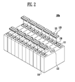
- FIG. 2 is an exploded perspective view of the battery module 100a shown in FIG. 1 .
- the battery module 100a according to this embodiment will be described with reference to FIGS. 1 and 2 .
- the battery module 100a includes a plurality of battery cells 110, bus-bars 120 configured to electrically connect between the battery cells 110, and a respective reflective portion 130 positioned at a terminal portion 111 of each of the battery cells 110.
- Each battery cell 110 includes a battery case of which one surface is opened, and an electrode assembly and an electrolyte, which are accommodated in the battery case.
- the electrode assembly and the electrolyte may generate energy through an electrochemical reaction therebetween.
- the open surface of the battery case is hermetically sealed by a cap assembly.
- terminal portions 111 having different polarities, i.e., positive and negative electrode terminals are provided to protrude from the cap plate.
- a vent portion 12 acting as a passage through which gas generated inside the battery cell 110 is exhausted to the outside of the battery cell 110 is further provided in the cap plate as a safety means of the battery cell 110.
- the plurality of battery cells 110 are aligned in one direction.
- the battery cells 110 are aligned so that the polarities of the terminal portions 111 of the battery cell 110 are different from each other.
- the battery cells 110 are connected in parallel, the battery cells 110 may be aligned so that the polarities of the terminal portions 111 of the battery cell 110 are identical to each other.
- Each bus-bar 120 is a member which electrically connects between two of the plurality of battery cells 110.
- the bus-bar 120 may be welded to the terminal portions 111 of the battery cell 110.
- the bus-bar 120 connects between the terminal portions 111 of adjacent battery cells 110 among the plurality of battery cells 110, thereby implementing the serial or parallel electrical connection between the battery cells 110.
- the bus-bar 120 may be welded to the terminal portions 111.
- an opening 121 is formed in the bus-bar 120 so that laser used in the welding can be incident between the bus-bar 120 and the terminal portion 111.
- a housing, a plate and the like, for fixing or accommodating the plurality of battery cells may be further added.
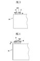
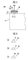
- FIGS. 3 and 4 are sectional views of battery modules compared with the battery module 100a shown in FIG. 1 .
- FIG. 5 is a sectional view taken along line A-A' of the battery module 100a shown in FIG. 1 .
- FIG. 6 is a sectional view showing various shapes of the reflective portion 130 of the battery module 100a shown in FIG. 5 .
- the reflective portion 130 of the battery module 100a according to this embodiment will be described with reference to FIGS. 3 to 6 .
- an opening is formed in the bus-bar so that laser used in the welding can be directed into the bus-bar therethrough.
- the laser is irradiated through an opening 11, in order ⁇ to be guided between the bus-bar 10 and a terminal portion 20.
- a welding portion is directly exposed to the outside of the bus-bar 20. Hence, this may not be preferable in terms of safety.
- a bus-bar 30 with a structure shown in FIG. 4 may be considered as a plan for solving such a problem.
- the opening 31 of the bus-bar 30 has a stepped shape, as shown in the structure of FIG. 4 , it may be difficult to accurately guide laser between an inner wall of the opening 31 and a terminal portion 40, i.e., to a welding portion 50.
- the laser is diagonally aimed, the laser reaches a place not to be welded as shown in FIG. 4 , and therefore, a portion of the bus-bar 30 outside the welding portion 50 may be damaged. This may not be preferable in terms of electrical safety.
- a reflective portion 130 is placed on the terminal portion 111 so that laser is transferred to a welding portion 140 through the reflection portion 130, thereby solving such a problem.
- the reflective portion 130 has at least one inclination surface 131, and the laser incident into the bus-bar 120 through the opening 121 is reflected on the inclination surface 131, to be guided to the interface between the bus-bar 120 and the terminal portion 111, i.e., to the welding portion 140.
- the opening 121 has a stepped shape. More specifically, the opening 121 includes a first opening 122 that is positioned relatively distant from the terminal portion 111, and a second opening 123 that is configured to communicate with the first opening 122 while being positioned relatively adjacent to the terminal portion 111. The second opening 123 has a diameter greater than that of the first opening 122.
- the reflective portion may be made of any reflective material suitable for a reflective portion appreciated by those skilled in the art, including silver, aluminum, copper, or a mirror material, the mirror having a glass layer and a metal layer coated on the glass layer.
- the reflective portion 130 is positioned inside the second opening 123 and reflects the laser so that at least one portion of the laser can be transferred to the point at which an inner wall defined by the second opening 123 and the terminal portion 111 meet each other. Accordingly, the terminal portion 111 and the bus-bar 120 are stably welded to each other, and simultaneously, the welding portion 140 is not directly exposed to the outside of the bus-bar 120, thereby improving electrical safety. Furthermore, because the first opening 122 is smaller than the second opening 123, the welding portion 140 receives relatively less influence from the outside.
- the reflective portion 130 is positioned on the terminal portion 111 in a place exposed through the opening 121. This may mean that when being straightly viewed through the opening 121, the reflective portion 130 is necessarily viewed otherwise, the laser cannot be directly focused on the reflective portion 130.
- the reflective portion 130 may be positioned directly below the first opening 122, so that the laser can be irradiated onto the inclination surface 131 of the reflective portion 130. Consequently, a portion of the reflective portion 130 may be melted by the irradiation of the laser, and the melted portion may enter between the bus-bar 120 and the terminal portion 111 to become a portion of the welding portion 140.
- the present invention is not limited thereto, and the reflective portion 130 may be made of a material which is not melted by the laser.
- the shape of the reflective portion 130 may be changed from the original shape.
- the reflective portion 130 may be formed in various shapes as shown in FIG. 6 . Specifically, as shown in FIG. 6(a) , a section of the reflective portion 130 may be formed in the shape of a triangle having at least one inclination surface 131. Alternatively, as shown in FIG. 6(b) , a section of the reflective portion 130' may be formed in the shape of a trapezoid having at least one inclination surface 131. Alternatively, as shown in FIG. 6(c) , a section of the reflective portion 130" may be formed in the shape of a semicircle having a curved surface 132. However, the present invention is not limited to these specific shapes, and it includes all shapes at which the laser incident into the bus-bar 120 through the opening 121 can be reflected. The reflectivity of the reflective portion 130 may be 80% or more.
- FIG. 7 is a sectional view of a battery module 100b according to a modification of the battery module 100a shown in FIG. 5 .
- the battery module 100b according to this embodiment will be described with reference to FIG. 7 .
- an opening 121b is provided that has a shape in which the diameter of the opening 121b narrows with distance from the terminal portion 111. Accordingly, the welding portion 140 is protected from exposure to the outside, thereby improving electrical safety.
- the irradiated laser is reflected by the reflective portion 130, so that at least one portion of the laser can be guided to the junction between the bus-bar 120 and the terminal portion 111.
- FIG. 8 is a sectional view of a battery module 100c according to another embodiment of the present invention.
- the battery module 100c according to the present invention will be described with reference to FIG. 8 .
- components identical to those of the aforementioned embodiment are designated by like reference numerals, and their detailed descriptions will be omitted to avoid redundancy.
- the battery module 100c includes the battery cell 110, the bus-bar 120 and the reflective portion 130.
- texture113 and 124 is formed on at least one of an inner wall of the bus-bar 120 and a top surface of the terminal portion 111.
- a portion of the laser may be guided to a point to be welded.
- the amount of the laser guided to the point to be welded may not be initially sufficient due to an error of the angle of the inclination surface 131 or the irradiation angle of the laser, or the amount of the laser guided to the point to be welded may degenerate due to a change in the angle of the inclination surface 131 while the reflective portion 130 is being melted by the laser.
- the texture 113 and 124 is formed on the inner wall of the opening 121 of the bus-bar 120 and/or the top surface of the terminal portion 111 in order to produce the diffused reflection.
- the texture 124 is formed on the inner wall of the second opening 123 of the bus-bar 120 and a stepped surface 125 of the second opening 123, and/or the texture 113 is formed on the top surface of the terminal portion 111 except the point at which the reflective portion 130 is positioned. Accordingly, if the laser reflected by the reflective portion 130 is not exactly guided to the point to be welded, the laser can be gradually guided to the welding portion 140 through being diffusely reflected in an inner space of the second opening 123. Thus, it is possible to conveniently perform the process of welding between the bus-bar 120 and the terminal portion 111. Further, the welding portion 140 can be firmly formed, thereby improving the electrical safety according to the connection of the bus-bar 120.
- FIG. 9 is a sectional view of a battery module 100d according to still another embodiment of the present invention.
- the battery module 100d according to the present invention will be described with reference to FIG. 9 .
- components identical to those of the aforementioned embodiment are designated by like reference numerals, and their detailed descriptions will be omitted to avoid redundancy.
- the battery module 100d includes the battery cell 110, the bus-bar 120 and a reflective portion 130d.
- a surface of the reflective portion 130d contacts a wall of the second opening 123.
- the reflective portion 130d includes a first reflective portion 133 and a second reflective portion 134.
- the first reflective portion 133 includes at least one inclination surface 131, and reflects, via the inclination surface 131, laser directed into the bus-bar 120 through the opening 121, to be an interface between the bus-bar 120 and the terminal portion 111.
- the second reflective portion 134 is positioned between the first reflective portion 133 and the terminal portion 111 so that a surface of the second reflective portion 134 is in contact with a wall of the second opening 123.
- the second reflective portion 134 locates against a laterally inner wall of the second opening 123, but the invention is not limited in this regard.
- the bus-bar 120 is mounted so that the outer surface of the second reflective portion 134 contacts the wall of the second opening 123, thereby facilitating the aligning process of the bus-bar 120.
- a portion of the second reflective portion 134 proximal the interface between the bus-bar 120 and the terminal portion 111, i.e., the point to be welded, may be melted by the laser and then enter between the bus-bar 120 and the terminal portion 111, to become a portion of the welding portion 140.
- the welding portion 140 can be more firmly formed, thereby further improving the electrical safety according to the connection of the bus-bar 120.
- a texture 124 is formed on the inner wall of the second opening 123 and the stepped surface 125 of the second opening 123 in order to produce diffused reflection. Furthermore, a texture 135 is formed on a top surface of the second reflective portion 134 in order to maximize the diffused reflection. In this case, the texture 135 is formed on the top surface of the second reflective portion 134 except where it is connected to the first reflective portion 133.
- FIG. 10 is a flowchart illustrating a method of manufacturing a battery module according to an embodiment of the present invention. Hereinafter, the method according to this embodiment will be described with reference to FIG. 10 .
- a plurality of battery cells 110 are first prepared (S110).
- the battery cells 110 may be prepared in an aligned state, and a reflective portion 130 is positioned on a top surface of a terminal portion 111 of each battery cell 110.
- bus-bars 120 for electrically connecting between the plurality of battery cells 110 are positioned on the terminal portions 111 (S120).
- the bus-bar 120 are disposed in accordance with whether a serial or parallel connection is required between the battery cells 110.
- bus-bar 120 and the terminal portion 111 are welded to each other (S130).
- a laser beam is directed through an opening 121 of each bus-bar 120 and reflected within the bus bar by the reflective portion 130.
- the laser reflected by the reflective portion 130 is guided to the point at which the bus-bar 120 and the terminal portion 111 meet each other so that the bus-bar 120 can be welded to the terminal portion 111.
- the battery module can be manufactured by the method described above, and it will be understood by those skilled in the art that the battery module may be variously modified by adding the texture, changing the shape of the reflective portion, or the like.
Landscapes
- Engineering & Computer Science (AREA)
- Physics & Mathematics (AREA)
- Optics & Photonics (AREA)
- Chemical & Material Sciences (AREA)
- Chemical Kinetics & Catalysis (AREA)
- Electrochemistry (AREA)
- General Chemical & Material Sciences (AREA)
- Mechanical Engineering (AREA)
- Plasma & Fusion (AREA)
- Connection Of Batteries Or Terminals (AREA)
Abstract
Description
- The present invention relates to a battery module and a method of manufacturing the same.
- A high-power battery module using a non-aqueous electrolyte with high energy density has recently been developed. The high-power battery module is configured as a high-voltage or large-capacity battery module manufactured by connecting a plurality of battery cells in parallel or series so as to be used in driving motors of devices requiring high power, e.g., electric vehicles and the like. Further, a battery pack can be configured by electrically connecting such a plurality of battery modules to one another.
- As the number of devices employing such a battery module increases, studies have been conducted to improve the productivity of the battery module. As the external appearance of the devices is diversified, it is required to vary the shape of the battery module. However, the safety of the battery module should be basically secured. Therefore, studies on the structure of a battery module capable of satisfying all the requirements have been conducted in various fields.
- The present invention sets out to provide a battery module and a method of manufacturing the same that can improve electrical safety when battery cells are connected through a bus-bar.
- According to an aspect of the present invention, there is provided a battery module, including: a plurality of battery cells each provided with a terminal portion; a bus-bar welded to the terminal portion to electrically connect between the plurality of battery cells, the bus-bar having an opening formed therein; and a reflective portion positioned on the terminal portion so that at least one portion of the reflective portion is exposed through the opening.
- The reflective portion may reflect laser incident into the bus-bar through the opening, so that the bus-bar is welded to the terminal portion.
- At least one portion of the laser reflected by the reflective portion may be guided between the bus-bar and the terminal portion.
- The opening of the bus-bar may have a stepped shape.
- The opening of the bus-bar may include a first opening, and a second opening configured to communicate with the first opening while being positioned adjacent to the terminal portion, the second opening having a diameter greater than that of the first opening.
- The reflective portion may be positioned in the second opening.
- At least one outer surface of the reflective portion may be contacted with an inner wall of the second opening.
- The reflective portion may include a first reflective portion configured to include at least one inclination surface, the first reflective portion reflecting, on the inclination surface, the laser incident into the bus-bar through the opening, to be guide between the bus-bar and the terminal portion, and a second reflective portion positioned between the first reflective portion and the terminal portion so that at least one outer surface of the second reflective portion is contacted with the inner wall of the second opening.
- An unevenness may be formed on the exposed surface of the second reflective portion.
- The opening of the bus-bar may have a shape in which the diameter of the opening is narrowed as the opening is distant from the terminal portion.
- The reflective portion may include at least one inclination surface.
- The laser incident into the bus-bar through the opening may be reflected on the inclination surface to weld between the bus-bar and the terminal portion.
- At least one portion of the reflective portion may be melted by the laser to be interposed between the bus-bar and the terminal portion.
- An unevenness may be formed on the inner wall of the bus-bar.
- An unevenness may be formed on the exposed surface of the terminal portion.
- The section of the reflective portion may have a triangular, trapezoid or curved surface shape.
- According to an aspect of the present invention, there is provided a method of manufacturing a battery module, the method including: preparing a plurality of battery cells each provided with terminal portion having a reflective portion positioned on a top surface thereof; placing a bus-bar electrically connecting between the plurality of battery cells on the terminal portion of the battery cell; and welding between the bus-bar and the terminal portion.
- In the welding, laser may be irradiated through an opening formed in the bus-bar.
- The irradiated laser may be reflected on the reflective portion so that at least one portion of the laser is guided to a point at which the bus-bar and the terminal portion meet each other.
- At least some of the above and other features of the invention are set out in the claims.
- Other features and advantages of the present invention will become more fully apparent from the following detailed description, taken in conjunction with the accompanying drawings.
- Terms or words used in this specification and claims should not be restrictively interpreted as ordinary meanings or dictionary-based meanings, but should be interpreted as meanings and concepts conforming to the scope of the present invention on the basis of the principle that an inventor can properly define the concept of a term to describe and explain his or her invention in the best ways.
- In the battery module and the method of manufacturing the same according to the present invention, the welding portion between the bus-bar and the terminal portion can be firmly formed without being directly exposed to the outside of the bus-bar, thereby improving electrical safety according to the connection of the bus-bar.
- Example embodiments of the invention will now be described more fully hereinafter with reference to the accompanying drawings; however, the invention may be embodied in different forms and should not be construed as limited to the embodiments set forth herein. Rather, these embodiments are provided so that this disclosure will be thorough, and will fully convey the scope of the example embodiments to those skilled in the art.
- In the drawing figures, dimensions may be exaggerated for clarity of illustration. It will be understood that when an element is referred to as being "between" two elements, it can be the only element between the two elements, or one or more intervening elements may also be present. Like reference numerals refer to like elements throughout.
-
FIG. 1 is a perspective view of a battery module according to an embodiment of the present invention. -
FIG. 2 is an exploded perspective view of the battery module shown inFIG. 1 . -
FIGS. 3 and 4 are sectional views of battery modules compared with the battery module shown inFIG. 1 . -
FIG. 5 is a sectional view taken along line A-A' of the battery module shown inFIG. 1 . -
FIG. 6 is a sectional view showing various shapes of a reflective portion of the battery module shown inFIG. 5 . -
FIG. 7 is a sectional view of a battery module according to a modification of the battery module shown inFIG. 5 . -
FIG. 8 is a sectional view of a battery module according to another embodiment of the present invention. -
FIG. 9 is a sectional view of a battery module according to still another embodiment of the present invention. -
FIG. 10 is a flowchart illustrating a method of manufacturing a battery module according to an embodiment of the present invention. - In the following detailed description, only certain exemplary embodiments of the present invention have been shown and described, simply by way of illustration. As those skilled in the art would realize, the described embodiments may be modified in various different ways, all without departing from the scope of the present invention. Accordingly, the drawings and description are to be regarded as illustrative in nature and not restrictive. In addition, when an element is referred to as being "on" another element, it can be directly on the another element or be indirectly on the another element with one or more intervening elements interposed therebetween. Also, when an element is referred to as being "connected to" another element, it can be directly connected to the another element or be indirectly connected to the another element with one or more intervening elements interposed therebetween. Hereinafter, like reference numerals refer to like elements.
-
FIG. 1 is a perspective view of abattery module 100a according to an embodiment of the present invention.FIG. 2 is an exploded perspective view of thebattery module 100a shown inFIG. 1 . Hereinafter, thebattery module 100a according to this embodiment will be described with reference toFIGS. 1 and2 . - As shown in
FIGS. 1 and2 , thebattery module 100a according to this embodiment includes a plurality ofbattery cells 110, bus-bars 120 configured to electrically connect between thebattery cells 110, and a respectivereflective portion 130 positioned at aterminal portion 111 of each of thebattery cells 110. - Each
battery cell 110 includes a battery case of which one surface is opened, and an electrode assembly and an electrolyte, which are accommodated in the battery case. In this case, the electrode assembly and the electrolyte may generate energy through an electrochemical reaction therebetween. The open surface of the battery case is hermetically sealed by a cap assembly. In addition,terminal portions 111 having different polarities, i.e., positive and negative electrode terminals are provided to protrude from the cap plate. A vent portion 12 acting as a passage through which gas generated inside thebattery cell 110 is exhausted to the outside of thebattery cell 110 is further provided in the cap plate as a safety means of thebattery cell 110. - The plurality of
battery cells 110 are aligned in one direction. When thebattery cells 110 are connected in series, thebattery cells 110 are aligned so that the polarities of theterminal portions 111 of thebattery cell 110 are different from each other. When thebattery cells 110 are connected in parallel, thebattery cells 110 may be aligned so that the polarities of theterminal portions 111 of thebattery cell 110 are identical to each other. - Each bus-
bar 120 is a member which electrically connects between two of the plurality ofbattery cells 110. The bus-bar 120 may be welded to theterminal portions 111 of thebattery cell 110. Here, the bus-bar 120 connects between theterminal portions 111 ofadjacent battery cells 110 among the plurality ofbattery cells 110, thereby implementing the serial or parallel electrical connection between thebattery cells 110. The bus-bar 120 may be welded to theterminal portions 111. To facilitate this, anopening 121 is formed in the bus-bar 120 so that laser used in the welding can be incident between the bus-bar 120 and theterminal portion 111. - Meanwhile, although not shown in these figures, a housing, a plate and the like, for fixing or accommodating the plurality of battery cells may be further added.
-
FIGS. 3 and 4 are sectional views of battery modules compared with thebattery module 100a shown inFIG. 1 .FIG. 5 is a sectional view taken along line A-A' of thebattery module 100a shown inFIG. 1 .FIG. 6 is a sectional view showing various shapes of thereflective portion 130 of thebattery module 100a shown inFIG. 5 . Hereinafter, thereflective portion 130 of thebattery module 100a according to this embodiment will be described with reference toFIGS. 3 to 6 . - As described above, an opening is formed in the bus-bar so that laser used in the welding can be directed into the bus-bar therethrough. In the case of the bus-
bar 10 shown inFIG. 3 , the laser is irradiated through an opening 11, in order \to be guided between the bus-bar 10 and aterminal portion 20. However, in such a structure, a welding portion is directly exposed to the outside of the bus-bar 20. Hence, this may not be preferable in terms of safety. - A bus-
bar 30 with a structure shown inFIG. 4 may be considered as a plan for solving such a problem. However, in a case where theopening 31 of the bus-bar 30 has a stepped shape, as shown in the structure ofFIG. 4 , it may be difficult to accurately guide laser between an inner wall of theopening 31 and aterminal portion 40, i.e., to awelding portion 50. Although the laser is diagonally aimed, the laser reaches a place not to be welded as shown inFIG. 4 , and therefore, a portion of the bus-bar 30 outside thewelding portion 50 may be damaged. This may not be preferable in terms of electrical safety. - In the present invention, as shown in
FIG. 5 , areflective portion 130 is placed on theterminal portion 111 so that laser is transferred to awelding portion 140 through thereflection portion 130, thereby solving such a problem. Specifically, thereflective portion 130 has at least oneinclination surface 131, and the laser incident into the bus-bar 120 through theopening 121 is reflected on theinclination surface 131, to be guided to the interface between the bus-bar 120 and theterminal portion 111, i.e., to thewelding portion 140. - In this case, the
opening 121 has a stepped shape. More specifically, theopening 121 includes afirst opening 122 that is positioned relatively distant from theterminal portion 111, and asecond opening 123 that is configured to communicate with thefirst opening 122 while being positioned relatively adjacent to theterminal portion 111. Thesecond opening 123 has a diameter greater than that of thefirst opening 122. - The reflective portion may be made of any reflective material suitable for a reflective portion appreciated by those skilled in the art, including silver, aluminum, copper, or a mirror material, the mirror having a glass layer and a metal layer coated on the glass layer.
- The
reflective portion 130 is positioned inside thesecond opening 123 and reflects the laser so that at least one portion of the laser can be transferred to the point at which an inner wall defined by thesecond opening 123 and theterminal portion 111 meet each other. Accordingly, theterminal portion 111 and the bus-bar 120 are stably welded to each other, and simultaneously, thewelding portion 140 is not directly exposed to the outside of the bus-bar 120, thereby improving electrical safety. Furthermore, because thefirst opening 122 is smaller than thesecond opening 123, thewelding portion 140 receives relatively less influence from the outside. - The
reflective portion 130 is positioned on theterminal portion 111 in a place exposed through theopening 121. This may mean that when being straightly viewed through theopening 121, thereflective portion 130 is necessarily viewed otherwise, the laser cannot be directly focused on thereflective portion 130. For example, thereflective portion 130 may be positioned directly below thefirst opening 122, so that the laser can be irradiated onto theinclination surface 131 of thereflective portion 130. Consequently, a portion of thereflective portion 130 may be melted by the irradiation of the laser, and the melted portion may enter between the bus-bar 120 and theterminal portion 111 to become a portion of thewelding portion 140. However, the present invention is not limited thereto, and thereflective portion 130 may be made of a material which is not melted by the laser. In addition, it will be apparent that when thewelding portion 140 is melted, the shape of thereflective portion 130 may be changed from the original shape. - The
reflective portion 130 may be formed in various shapes as shown inFIG. 6 . Specifically, as shown inFIG. 6(a) , a section of thereflective portion 130 may be formed in the shape of a triangle having at least oneinclination surface 131. Alternatively, as shown inFIG. 6(b) , a section of the reflective portion 130' may be formed in the shape of a trapezoid having at least oneinclination surface 131. Alternatively, as shown inFIG. 6(c) , a section of thereflective portion 130" may be formed in the shape of a semicircle having acurved surface 132. However, the present invention is not limited to these specific shapes, and it includes all shapes at which the laser incident into the bus-bar 120 through theopening 121 can be reflected. The reflectivity of thereflective portion 130 may be 80% or more. -
FIG. 7 is a sectional view of abattery module 100b according to a modification of thebattery module 100a shown inFIG. 5 . Hereinafter, thebattery module 100b according to this embodiment will be described with reference toFIG. 7 . - In case of the bus-
bar 120b shown inFIG. 7 , anopening 121b is provided that has a shape in which the diameter of theopening 121b narrows with distance from theterminal portion 111. Accordingly, thewelding portion 140 is protected from exposure to the outside, thereby improving electrical safety. In a case where laser is irradiated to weld the bus-bar 120b and theterminal portion 111, the irradiated laser is reflected by thereflective portion 130, so that at least one portion of the laser can be guided to the junction between the bus-bar 120 and theterminal portion 111. Thus, it is possible to conveniently perform the process of welding between the bus-bar 120b and theterminal portion 111 and to improve the electrical safety. -
FIG. 8 is a sectional view of abattery module 100c according to another embodiment of the present invention. Hereinafter, thebattery module 100c according to the present invention will be described with reference toFIG. 8 . Here, components identical to those of the aforementioned embodiment are designated by like reference numerals, and their detailed descriptions will be omitted to avoid redundancy. - As shown in
FIG. 8 , thebattery module 100c according to this embodiment includes thebattery cell 110, the bus-bar 120 and thereflective portion 130. In this case, texture113 and 124 is formed on at least one of an inner wall of the bus-bar 120 and a top surface of theterminal portion 111. - In a case where the
reflective portion 130 is included as described above, a portion of the laser may be guided to a point to be welded. However, the amount of the laser guided to the point to be welded may not be initially sufficient due to an error of the angle of theinclination surface 131 or the irradiation angle of the laser, or the amount of the laser guided to the point to be welded may degenerate due to a change in the angle of theinclination surface 131 while thereflective portion 130 is being melted by the laser. In this case, if diffused reflection is produced around the point to be welded, the amount of the laser guided to the point to be welded can be increased. In this embodiment, thetexture opening 121 of the bus-bar 120 and/or the top surface of theterminal portion 111 in order to produce the diffused reflection. - Specifically, the
texture 124 is formed on the inner wall of thesecond opening 123 of the bus-bar 120 and a steppedsurface 125 of thesecond opening 123, and/or thetexture 113 is formed on the top surface of theterminal portion 111 except the point at which thereflective portion 130 is positioned. Accordingly, if the laser reflected by thereflective portion 130 is not exactly guided to the point to be welded, the laser can be gradually guided to thewelding portion 140 through being diffusely reflected in an inner space of thesecond opening 123. Thus, it is possible to conveniently perform the process of welding between the bus-bar 120 and theterminal portion 111. Further, thewelding portion 140 can be firmly formed, thereby improving the electrical safety according to the connection of the bus-bar 120. -
FIG. 9 is a sectional view of abattery module 100d according to still another embodiment of the present invention. Hereinafter, thebattery module 100d according to the present invention will be described with reference toFIG. 9 . Here, components identical to those of the aforementioned embodiment are designated by like reference numerals, and their detailed descriptions will be omitted to avoid redundancy. - As shown in
FIG. 9 , thebattery module 100d according to this embodiment includes thebattery cell 110, the bus-bar 120 and a reflective portion 130d. In this case, a surface of the reflective portion 130d contacts a wall of thesecond opening 123. Specifically, the reflective portion 130d includes a firstreflective portion 133 and a secondreflective portion 134. Here, the firstreflective portion 133 includes at least oneinclination surface 131, and reflects, via theinclination surface 131, laser directed into the bus-bar 120 through theopening 121, to be an interface between the bus-bar 120 and theterminal portion 111. The secondreflective portion 134 is positioned between the firstreflective portion 133 and theterminal portion 111 so that a surface of the secondreflective portion 134 is in contact with a wall of thesecond opening 123. - In this embodiment, the second
reflective portion 134 locates against a laterally inner wall of thesecond opening 123, but the invention is not limited in this regard. - Accordingly, the bus-
bar 120 is mounted so that the outer surface of the secondreflective portion 134 contacts the wall of thesecond opening 123, thereby facilitating the aligning process of the bus-bar 120. In addition, a portion of the secondreflective portion 134 proximal the interface between the bus-bar 120 and theterminal portion 111, i.e., the point to be welded, may be melted by the laser and then enter between the bus-bar 120 and theterminal portion 111, to become a portion of thewelding portion 140. Thus, thewelding portion 140 can be more firmly formed, thereby further improving the electrical safety according to the connection of the bus-bar 120. - As described in relation to the preceding embodiment, a
texture 124 is formed on the inner wall of thesecond opening 123 and the steppedsurface 125 of thesecond opening 123 in order to produce diffused reflection. Furthermore, atexture 135 is formed on a top surface of the secondreflective portion 134 in order to maximize the diffused reflection. In this case, thetexture 135 is formed on the top surface of the secondreflective portion 134 except where it is connected to the firstreflective portion 133. -
FIG. 10 is a flowchart illustrating a method of manufacturing a battery module according to an embodiment of the present invention. Hereinafter, the method according to this embodiment will be described with reference toFIG. 10 . - In order to manufacture the battery module according to this embodiment, a plurality of
battery cells 110 are first prepared (S110). In this case, thebattery cells 110 may be prepared in an aligned state, and areflective portion 130 is positioned on a top surface of aterminal portion 111 of eachbattery cell 110. - Next, bus-
bars 120 for electrically connecting between the plurality ofbattery cells 110 are positioned on the terminal portions 111 (S120). The bus-bar 120 are disposed in accordance with whether a serial or parallel connection is required between thebattery cells 110. - Next, the bus-
bar 120 and theterminal portion 111 are welded to each other (S130). In this case, a laser beam is directed through anopening 121 of each bus-bar 120 and reflected within the bus bar by thereflective portion 130. The laser reflected by thereflective portion 130 is guided to the point at which the bus-bar 120 and theterminal portion 111 meet each other so that the bus-bar 120 can be welded to theterminal portion 111. - The battery module can be manufactured by the method described above, and it will be understood by those skilled in the art that the battery module may be variously modified by adding the texture, changing the shape of the reflective portion, or the like.
- Embodiments of the invention have been disclosed herein, and although specific terms are employed, they are used and are to be interpreted in a generic and descriptive sense only and not for purpose of limitation. In some instances, as would be apparent to one of ordinary skill in the art as of the filing of the present application, features, characteristics, and/or elements described in connection with a particular embodiment may be used singly or in combination with features, characteristics, and/or elements described in connection with other embodiments unless otherwise specifically indicated. Accordingly, it will be understood by those of skill in the art that various changes in form and details may be made without departing from the scope of the present invention as set forth in the following claims.
Claims (17)
- A battery module, comprising:a plurality of battery cells, each provided with a terminal portion;a bus-bar coupled to the terminal portions in order to electrically connect between the plurality of battery cells, the bus-bar having an opening formed therein; anda reflective portion positioned on one of the terminal portions so that a light-reflective surface of the reflective portion is exposed through the opening.
- A battery module according to claim 1, wherein the light-reflective surface is at least partially adapted to direct light towards a position at which the bus-bar is coupled to the terminal portion.
- A battery module according to claim 2, wherein the light-reflective surface is adapted to direct light towards a position situated between the bus-bar and the terminal portion.
- A battery module according to any preceding claim, wherein the opening of the bus-bar has a stepped shape.
- A battery module according to claim 4, wherein the opening of the bus-bar includes a first opening and a second opening configured to communicate with the first opening while being positioned adjacent to the terminal portion, the second opening having a diameter greater than that of the first opening.
- A battery module according to claim 5, wherein the reflective portion is positioned in the second opening.
- A battery module according to claim 5 or 6, wherein at least one surface of the reflective portion contacts a wall of the second opening.
- A battery module according to claim 7, wherein the reflective portion includes a first reflective portion comprising the said light-reflective surface and a second reflective portion positioned between the first reflective portion and the terminal portion, so that at least one surface of the second reflective portion contacts a wall of the second opening.
- A battery module according to claim 8, wherein a texture is formed on the second reflective portion.
- A battery module according to any preceding claim, wherein the opening of the bus-bar has a shape in which the size of the opening narrows with distance from the terminal portion.
- A battery module according to any preceding claim, wherein light-reflective surface includes at least one inclined part.
- A battery module according to any preceding claim, wherein a texture is formed on an inner wall of the bus-bar.
- A battery module according to any preceding claim, wherein a texture is formed on an exposed surface of the terminal portion.
- A battery module according to any preceding claim, wherein at least a part of the reflective portion has a triangular, trapezoid or curved surface shape.
- A method of manufacturing a battery module, the method comprising:providing a plurality of battery cells wherein at least one of which has a terminal portion comprising a reflective portion on a surface thereof;placing a bus-bar for electrically connecting between the plurality of battery cells on the terminal portion of the battery cell, the said bus bar having an opening formed therein;applying laser light to the reflective portion via the said opening; andforming a weld between the bus-bar and the said terminal portion using laser light reflected from a light-reflective surface of the said reflective portion.
- A method according to claim 15, wherein the irradiated laser is reflected on the light-reflective surface so that at least one portion of the laser is guided to a point at which the bus-bar and the terminal portion meet each other.
- A method according to claim 15 or 16, wherein at least a portion of the reflective portion is melted by the laser so as to be interposed between the bus-bar and the terminal portion.
Applications Claiming Priority (1)
| Application Number | Priority Date | Filing Date | Title |
|---|---|---|---|
| KR1020140014186A KR102140212B1 (en) | 2014-02-07 | 2014-02-07 | Battery module and method of manufacturing the same |
Publications (2)
| Publication Number | Publication Date |
|---|---|
| EP2905826A1 true EP2905826A1 (en) | 2015-08-12 |
| EP2905826B1 EP2905826B1 (en) | 2017-03-01 |
Family
ID=51298537
Family Applications (1)
| Application Number | Title | Priority Date | Filing Date |
|---|---|---|---|
| EP14178826.5A Active EP2905826B1 (en) | 2014-02-07 | 2014-07-28 | Battery module and method of manufacturing the same |
Country Status (5)
| Country | Link |
|---|---|
| US (1) | US9673438B2 (en) |
| EP (1) | EP2905826B1 (en) |
| JP (1) | JP6566544B2 (en) |
| KR (1) | KR102140212B1 (en) |
| CN (1) | CN104835934B (en) |
Cited By (2)
| Publication number | Priority date | Publication date | Assignee | Title |
|---|---|---|---|---|
| CN109616606A (en) * | 2017-09-29 | 2019-04-12 | Sk新技术株式会社 | Battery module for secondary battery |
| EP4586380A1 (en) * | 2024-01-11 | 2025-07-16 | Techtronic Cordless GP | Battery pack |
Families Citing this family (15)
| Publication number | Priority date | Publication date | Assignee | Title |
|---|---|---|---|---|
| FR3016478B1 (en) * | 2014-01-16 | 2017-09-08 | Commissariat Energie Atomique | ELECTROCHEMICAL BATTERY WITH HOUSING AND ALUMINUM ALLOY OUTPUT TERMINAL, BATTERY PACK AND METHOD OF MAKING THE SAME |
| JP6635294B2 (en) * | 2015-12-15 | 2020-01-22 | 株式会社オートネットワーク技術研究所 | Bus bar and power storage module |
| JP6861376B2 (en) * | 2016-05-31 | 2021-04-21 | パナソニックIpマネジメント株式会社 | Method of forming terminal connection structure, battery laminate and terminal connection structure |
| JP6907633B2 (en) * | 2017-03-27 | 2021-07-21 | 日本電気株式会社 | Module parts and manufacturing method of module parts |
| US10158104B1 (en) * | 2017-07-21 | 2018-12-18 | Swift Engineering, Inc. | Power cell casing |
| KR102598811B1 (en) | 2018-03-06 | 2023-11-03 | 에스케이온 주식회사 | Battery module and its manufacturing method |
| CN208127292U (en) * | 2018-03-15 | 2018-11-20 | 宁德时代新能源科技股份有限公司 | Busbar connector and battery modules |
| KR102258177B1 (en) | 2018-09-20 | 2021-05-28 | 주식회사 엘지에너지솔루션 | Battery module, battery pack comprising the battery module and vehicle comprising the battery pack |
| DE102019001893A1 (en) * | 2019-03-18 | 2019-11-14 | Daimler Ag | Method for producing electrical connections of at least two battery cells for a battery of a motor vehicle, in particular of a motor vehicle |
| EP4303997A4 (en) * | 2021-03-01 | 2025-06-25 | Vehicle Energy Japan Inc. | Assembled battery and method for manufacturing assembled battery |
| DE102021122892A1 (en) * | 2021-09-03 | 2023-03-09 | Te Connectivity Germany Gmbh | Semi-finished product provided with a window for laser welding for producing an electrical contact element and method for producing an electrical contact element and electrical contact element |
| DE102022004058B3 (en) * | 2022-10-31 | 2024-03-07 | Mercedes-Benz Group AG | Cell connector for electrically contacting a first pole of a first battery cell with a second pole of a second battery cell and battery arrangement |
| KR20240087269A (en) | 2022-12-12 | 2024-06-19 | 현대자동차주식회사 | Battery module |
| KR20250012365A (en) * | 2023-07-17 | 2025-01-24 | 주식회사 엘지에너지솔루션 | Secondary battery module frame and secondary battery module including the same |
| JP2025136290A (en) * | 2024-03-07 | 2025-09-19 | プライムプラネットエナジー&ソリューションズ株式会社 | Battery assembly manufacturing device, battery assembly manufacturing method, and laser light attenuation mechanism |
Citations (3)
| Publication number | Priority date | Publication date | Assignee | Title |
|---|---|---|---|---|
| US20120055909A1 (en) * | 2009-05-15 | 2012-03-08 | Hideaki Miyake | Method of laser-welding and method of manufacturing battery including the same |
| US20130269978A1 (en) * | 2012-04-12 | 2013-10-17 | Robert Bosch Gmbh | Battery module |
| US20130344378A1 (en) * | 2011-03-10 | 2013-12-26 | Sanyo Electric Co., Ltd. | Assembled battery and cell connection method |
Family Cites Families (6)
| Publication number | Priority date | Publication date | Assignee | Title |
|---|---|---|---|---|
| JPS63140786A (en) * | 1986-12-03 | 1988-06-13 | Fuji Electric Co Ltd | Laser welding method |
| JP5122857B2 (en) * | 2007-04-23 | 2013-01-16 | 株式会社東芝 | Battery module and battery module connection method |
| JP5657307B2 (en) * | 2010-08-20 | 2015-01-21 | 株式会社東芝 | Welding method, battery, method for manufacturing battery pack, and battery |
| JP5528571B2 (en) | 2010-11-08 | 2014-06-25 | パナソニック株式会社 | Battery module and battery module welding method |
| KR101240453B1 (en) | 2010-11-12 | 2013-03-11 | 아이피지 포토닉스 코리아(주) | Apparatus and Method for Welding of Electrode of Secondary Battery |
| KR20130047506A (en) | 2011-10-31 | 2013-05-08 | 에이치엘그린파워 주식회사 | Laser welding apparatus for secondary battery |
-
2014
- 2014-02-07 KR KR1020140014186A patent/KR102140212B1/en active Active
- 2014-07-28 EP EP14178826.5A patent/EP2905826B1/en active Active
- 2014-08-13 US US14/459,103 patent/US9673438B2/en active Active
- 2014-12-30 CN CN201410840946.9A patent/CN104835934B/en active Active
-
2015
- 2015-02-03 JP JP2015019652A patent/JP6566544B2/en active Active
Patent Citations (3)
| Publication number | Priority date | Publication date | Assignee | Title |
|---|---|---|---|---|
| US20120055909A1 (en) * | 2009-05-15 | 2012-03-08 | Hideaki Miyake | Method of laser-welding and method of manufacturing battery including the same |
| US20130344378A1 (en) * | 2011-03-10 | 2013-12-26 | Sanyo Electric Co., Ltd. | Assembled battery and cell connection method |
| US20130269978A1 (en) * | 2012-04-12 | 2013-10-17 | Robert Bosch Gmbh | Battery module |
Cited By (3)
| Publication number | Priority date | Publication date | Assignee | Title |
|---|---|---|---|---|
| CN109616606A (en) * | 2017-09-29 | 2019-04-12 | Sk新技术株式会社 | Battery module for secondary battery |
| CN109616606B (en) * | 2017-09-29 | 2022-10-21 | Sk新能源株式会社 | Battery module for secondary battery |
| EP4586380A1 (en) * | 2024-01-11 | 2025-07-16 | Techtronic Cordless GP | Battery pack |
Also Published As
| Publication number | Publication date |
|---|---|
| US9673438B2 (en) | 2017-06-06 |
| JP6566544B2 (en) | 2019-08-28 |
| JP2015149282A (en) | 2015-08-20 |
| US20150228957A1 (en) | 2015-08-13 |
| CN104835934B (en) | 2020-01-17 |
| KR20150093426A (en) | 2015-08-18 |
| KR102140212B1 (en) | 2020-07-31 |
| CN104835934A (en) | 2015-08-12 |
| EP2905826B1 (en) | 2017-03-01 |
Similar Documents
| Publication | Publication Date | Title |
|---|---|---|
| EP2905826B1 (en) | Battery module and method of manufacturing the same | |
| JP6806217B2 (en) | Rechargeable battery | |
| CN108370017B (en) | Bus bar and electricity storage module | |
| EP2887427A1 (en) | Battery module with bus-bar holder | |
| US9548475B2 (en) | Battery cell of irregular structure and battery module employed with the same | |
| CN107251270B (en) | Battery system | |
| US20220200108A1 (en) | Secondary battery | |
| KR102271383B1 (en) | Cell module and its manufacturing method | |
| US11342632B2 (en) | Battery module | |
| US20110223478A1 (en) | Secondary battery and secondary battery module using the same | |
| KR20190000210A (en) | Battery pack | |
| US9590280B2 (en) | Battery pack | |
| CN110931695B (en) | Battery module, battery pack including battery module, and vehicle including battery pack | |
| US20140315070A1 (en) | Battery module | |
| EP3711104B1 (en) | Power unit made up of a solder-free assembly of a plurality of battery cells | |
| KR20150024560A (en) | Battery module | |
| JP2019084540A (en) | Method of manufacturing sealed battery | |
| JP2006344572A (en) | Electric device module manufacturing method and electric device module | |
| KR101675617B1 (en) | Method of stacking battery as bending electrode tabs | |
| KR102424640B1 (en) | Battery module and Method for assembling the same | |
| CN109314197A (en) | rechargeable battery | |
| US20230261336A1 (en) | Welding Method and Electrode Assembly Manufactured by the Same | |
| KR102411730B1 (en) | The Secondary Battery And The Battery Module | |
| EP4647204A1 (en) | Jig for laser welding and method of manufacturing battery | |
| US20260100457A1 (en) | Battery Cell, and Battery Pack and Vehicle Including the Same |
Legal Events
| Date | Code | Title | Description |
|---|---|---|---|
| PUAI | Public reference made under article 153(3) epc to a published international application that has entered the european phase |
Free format text: ORIGINAL CODE: 0009012 |
|
| AK | Designated contracting states |
Kind code of ref document: A1 Designated state(s): AL AT BE BG CH CY CZ DE DK EE ES FI FR GB GR HR HU IE IS IT LI LT LU LV MC MK MT NL NO PL PT RO RS SE SI SK SM TR |
|
| AX | Request for extension of the european patent |
Extension state: BA ME |
|
| 17P | Request for examination filed |
Effective date: 20150728 |
|
| RBV | Designated contracting states (corrected) |
Designated state(s): AL AT BE BG CH CY CZ DE DK EE ES FI FR GB GR HR HU IE IS IT LI LT LU LV MC MK MT NL NO PL PT RO RS SE SI SK SM TR |
|
| 17Q | First examination report despatched |
Effective date: 20151117 |
|
| GRAP | Despatch of communication of intention to grant a patent |
Free format text: ORIGINAL CODE: EPIDOSNIGR1 |
|
| RIC1 | Information provided on ipc code assigned before grant |
Ipc: H01M 2/20 20060101AFI20160901BHEP Ipc: B23K 101/38 20060101ALN20160901BHEP Ipc: B23K 26/20 20140101ALI20160901BHEP Ipc: H01M 2/30 20060101ALI20160901BHEP Ipc: B23K 31/02 20060101ALI20160901BHEP |
|
| INTG | Intention to grant announced |
Effective date: 20160913 |
|
| GRAS | Grant fee paid |
Free format text: ORIGINAL CODE: EPIDOSNIGR3 |
|
| GRAA | (expected) grant |
Free format text: ORIGINAL CODE: 0009210 |
|
| AK | Designated contracting states |
Kind code of ref document: B1 Designated state(s): AL AT BE BG CH CY CZ DE DK EE ES FI FR GB GR HR HU IE IS IT LI LT LU LV MC MK MT NL NO PL PT RO RS SE SI SK SM TR |
|
| REG | Reference to a national code |
Ref country code: GB Ref legal event code: FG4D |
|
| REG | Reference to a national code |
Ref country code: CH Ref legal event code: EP Ref country code: AT Ref legal event code: REF Ref document number: 872272 Country of ref document: AT Kind code of ref document: T Effective date: 20170315 |
|
| REG | Reference to a national code |
Ref country code: IE Ref legal event code: FG4D |
|
| REG | Reference to a national code |
Ref country code: DE Ref legal event code: R096 Ref document number: 602014007046 Country of ref document: DE |
|
| REG | Reference to a national code |
Ref country code: FR Ref legal event code: PLFP Year of fee payment: 4 |
|
| REG | Reference to a national code |
Ref country code: NL Ref legal event code: MP Effective date: 20170301 |
|
| REG | Reference to a national code |
Ref country code: LT Ref legal event code: MG4D |
|
| REG | Reference to a national code |
Ref country code: AT Ref legal event code: MK05 Ref document number: 872272 Country of ref document: AT Kind code of ref document: T Effective date: 20170301 |
|
| PG25 | Lapsed in a contracting state [announced via postgrant information from national office to epo] |
Ref country code: GR Free format text: LAPSE BECAUSE OF FAILURE TO SUBMIT A TRANSLATION OF THE DESCRIPTION OR TO PAY THE FEE WITHIN THE PRESCRIBED TIME-LIMIT Effective date: 20170602 Ref country code: FI Free format text: LAPSE BECAUSE OF FAILURE TO SUBMIT A TRANSLATION OF THE DESCRIPTION OR TO PAY THE FEE WITHIN THE PRESCRIBED TIME-LIMIT Effective date: 20170301 Ref country code: LT Free format text: LAPSE BECAUSE OF FAILURE TO SUBMIT A TRANSLATION OF THE DESCRIPTION OR TO PAY THE FEE WITHIN THE PRESCRIBED TIME-LIMIT Effective date: 20170301 Ref country code: NO Free format text: LAPSE BECAUSE OF FAILURE TO SUBMIT A TRANSLATION OF THE DESCRIPTION OR TO PAY THE FEE WITHIN THE PRESCRIBED TIME-LIMIT Effective date: 20170601 Ref country code: HR Free format text: LAPSE BECAUSE OF FAILURE TO SUBMIT A TRANSLATION OF THE DESCRIPTION OR TO PAY THE FEE WITHIN THE PRESCRIBED TIME-LIMIT Effective date: 20170301 |
|
| PG25 | Lapsed in a contracting state [announced via postgrant information from national office to epo] |
Ref country code: ES Free format text: LAPSE BECAUSE OF FAILURE TO SUBMIT A TRANSLATION OF THE DESCRIPTION OR TO PAY THE FEE WITHIN THE PRESCRIBED TIME-LIMIT Effective date: 20170301 Ref country code: SE Free format text: LAPSE BECAUSE OF FAILURE TO SUBMIT A TRANSLATION OF THE DESCRIPTION OR TO PAY THE FEE WITHIN THE PRESCRIBED TIME-LIMIT Effective date: 20170301 Ref country code: BG Free format text: LAPSE BECAUSE OF FAILURE TO SUBMIT A TRANSLATION OF THE DESCRIPTION OR TO PAY THE FEE WITHIN THE PRESCRIBED TIME-LIMIT Effective date: 20170601 Ref country code: AT Free format text: LAPSE BECAUSE OF FAILURE TO SUBMIT A TRANSLATION OF THE DESCRIPTION OR TO PAY THE FEE WITHIN THE PRESCRIBED TIME-LIMIT Effective date: 20170301 Ref country code: LV Free format text: LAPSE BECAUSE OF FAILURE TO SUBMIT A TRANSLATION OF THE DESCRIPTION OR TO PAY THE FEE WITHIN THE PRESCRIBED TIME-LIMIT Effective date: 20170301 Ref country code: RS Free format text: LAPSE BECAUSE OF FAILURE TO SUBMIT A TRANSLATION OF THE DESCRIPTION OR TO PAY THE FEE WITHIN THE PRESCRIBED TIME-LIMIT Effective date: 20170301 |
|
| PG25 | Lapsed in a contracting state [announced via postgrant information from national office to epo] |
Ref country code: NL Free format text: LAPSE BECAUSE OF FAILURE TO SUBMIT A TRANSLATION OF THE DESCRIPTION OR TO PAY THE FEE WITHIN THE PRESCRIBED TIME-LIMIT Effective date: 20170301 |
|
| PG25 | Lapsed in a contracting state [announced via postgrant information from national office to epo] |
Ref country code: EE Free format text: LAPSE BECAUSE OF FAILURE TO SUBMIT A TRANSLATION OF THE DESCRIPTION OR TO PAY THE FEE WITHIN THE PRESCRIBED TIME-LIMIT Effective date: 20170301 Ref country code: IT Free format text: LAPSE BECAUSE OF FAILURE TO SUBMIT A TRANSLATION OF THE DESCRIPTION OR TO PAY THE FEE WITHIN THE PRESCRIBED TIME-LIMIT Effective date: 20170301 Ref country code: SK Free format text: LAPSE BECAUSE OF FAILURE TO SUBMIT A TRANSLATION OF THE DESCRIPTION OR TO PAY THE FEE WITHIN THE PRESCRIBED TIME-LIMIT Effective date: 20170301 Ref country code: CZ Free format text: LAPSE BECAUSE OF FAILURE TO SUBMIT A TRANSLATION OF THE DESCRIPTION OR TO PAY THE FEE WITHIN THE PRESCRIBED TIME-LIMIT Effective date: 20170301 Ref country code: RO Free format text: LAPSE BECAUSE OF FAILURE TO SUBMIT A TRANSLATION OF THE DESCRIPTION OR TO PAY THE FEE WITHIN THE PRESCRIBED TIME-LIMIT Effective date: 20170301 |
|
| PG25 | Lapsed in a contracting state [announced via postgrant information from national office to epo] |
Ref country code: SM Free format text: LAPSE BECAUSE OF FAILURE TO SUBMIT A TRANSLATION OF THE DESCRIPTION OR TO PAY THE FEE WITHIN THE PRESCRIBED TIME-LIMIT Effective date: 20170301 Ref country code: IS Free format text: LAPSE BECAUSE OF FAILURE TO SUBMIT A TRANSLATION OF THE DESCRIPTION OR TO PAY THE FEE WITHIN THE PRESCRIBED TIME-LIMIT Effective date: 20170701 Ref country code: PL Free format text: LAPSE BECAUSE OF FAILURE TO SUBMIT A TRANSLATION OF THE DESCRIPTION OR TO PAY THE FEE WITHIN THE PRESCRIBED TIME-LIMIT Effective date: 20170301 Ref country code: PT Free format text: LAPSE BECAUSE OF FAILURE TO SUBMIT A TRANSLATION OF THE DESCRIPTION OR TO PAY THE FEE WITHIN THE PRESCRIBED TIME-LIMIT Effective date: 20170703 |
|
| REG | Reference to a national code |
Ref country code: DE Ref legal event code: R097 Ref document number: 602014007046 Country of ref document: DE |
|
| PLBE | No opposition filed within time limit |
Free format text: ORIGINAL CODE: 0009261 |
|
| STAA | Information on the status of an ep patent application or granted ep patent |
Free format text: STATUS: NO OPPOSITION FILED WITHIN TIME LIMIT |
|
| PG25 | Lapsed in a contracting state [announced via postgrant information from national office to epo] |
Ref country code: DK Free format text: LAPSE BECAUSE OF FAILURE TO SUBMIT A TRANSLATION OF THE DESCRIPTION OR TO PAY THE FEE WITHIN THE PRESCRIBED TIME-LIMIT Effective date: 20170301 |
|
| 26N | No opposition filed |
Effective date: 20171204 |
|
| PG25 | Lapsed in a contracting state [announced via postgrant information from national office to epo] |
Ref country code: SI Free format text: LAPSE BECAUSE OF FAILURE TO SUBMIT A TRANSLATION OF THE DESCRIPTION OR TO PAY THE FEE WITHIN THE PRESCRIBED TIME-LIMIT Effective date: 20170301 |
|
| REG | Reference to a national code |
Ref country code: CH Ref legal event code: PL |
|
| REG | Reference to a national code |
Ref country code: IE Ref legal event code: MM4A |
|
| PG25 | Lapsed in a contracting state [announced via postgrant information from national office to epo] |
Ref country code: IE Free format text: LAPSE BECAUSE OF NON-PAYMENT OF DUE FEES Effective date: 20170728 Ref country code: LI Free format text: LAPSE BECAUSE OF NON-PAYMENT OF DUE FEES Effective date: 20170731 Ref country code: CH Free format text: LAPSE BECAUSE OF NON-PAYMENT OF DUE FEES Effective date: 20170731 |
|
| REG | Reference to a national code |
Ref country code: BE Ref legal event code: MM Effective date: 20170731 |
|
| PG25 | Lapsed in a contracting state [announced via postgrant information from national office to epo] |
Ref country code: LU Free format text: LAPSE BECAUSE OF NON-PAYMENT OF DUE FEES Effective date: 20170728 |
|
| REG | Reference to a national code |
Ref country code: FR Ref legal event code: PLFP Year of fee payment: 5 |
|
| PG25 | Lapsed in a contracting state [announced via postgrant information from national office to epo] |
Ref country code: BE Free format text: LAPSE BECAUSE OF NON-PAYMENT OF DUE FEES Effective date: 20170731 |
|
| PG25 | Lapsed in a contracting state [announced via postgrant information from national office to epo] |
Ref country code: MT Free format text: LAPSE BECAUSE OF NON-PAYMENT OF DUE FEES Effective date: 20170728 |
|
| PG25 | Lapsed in a contracting state [announced via postgrant information from national office to epo] |
Ref country code: MC Free format text: LAPSE BECAUSE OF FAILURE TO SUBMIT A TRANSLATION OF THE DESCRIPTION OR TO PAY THE FEE WITHIN THE PRESCRIBED TIME-LIMIT Effective date: 20170301 Ref country code: HU Free format text: LAPSE BECAUSE OF FAILURE TO SUBMIT A TRANSLATION OF THE DESCRIPTION OR TO PAY THE FEE WITHIN THE PRESCRIBED TIME-LIMIT; INVALID AB INITIO Effective date: 20140728 |
|
| PG25 | Lapsed in a contracting state [announced via postgrant information from national office to epo] |
Ref country code: CY Free format text: LAPSE BECAUSE OF FAILURE TO SUBMIT A TRANSLATION OF THE DESCRIPTION OR TO PAY THE FEE WITHIN THE PRESCRIBED TIME-LIMIT Effective date: 20170301 |
|
| PG25 | Lapsed in a contracting state [announced via postgrant information from national office to epo] |
Ref country code: MK Free format text: LAPSE BECAUSE OF FAILURE TO SUBMIT A TRANSLATION OF THE DESCRIPTION OR TO PAY THE FEE WITHIN THE PRESCRIBED TIME-LIMIT Effective date: 20170301 |
|
| PG25 | Lapsed in a contracting state [announced via postgrant information from national office to epo] |
Ref country code: TR Free format text: LAPSE BECAUSE OF FAILURE TO SUBMIT A TRANSLATION OF THE DESCRIPTION OR TO PAY THE FEE WITHIN THE PRESCRIBED TIME-LIMIT Effective date: 20170301 |
|
| PG25 | Lapsed in a contracting state [announced via postgrant information from national office to epo] |
Ref country code: AL Free format text: LAPSE BECAUSE OF FAILURE TO SUBMIT A TRANSLATION OF THE DESCRIPTION OR TO PAY THE FEE WITHIN THE PRESCRIBED TIME-LIMIT Effective date: 20170301 |
|
| REG | Reference to a national code |
Ref country code: DE Ref legal event code: R079 Ref document number: 602014007046 Country of ref document: DE Free format text: PREVIOUS MAIN CLASS: H01M0002200000 Ipc: H01M0050500000 |
|
| P01 | Opt-out of the competence of the unified patent court (upc) registered |
Effective date: 20230528 |
|
| PGFP | Annual fee paid to national office [announced via postgrant information from national office to epo] |
Ref country code: GB Payment date: 20250626 Year of fee payment: 12 |
|
| PGFP | Annual fee paid to national office [announced via postgrant information from national office to epo] |
Ref country code: FR Payment date: 20250623 Year of fee payment: 12 |
|
| PGFP | Annual fee paid to national office [announced via postgrant information from national office to epo] |
Ref country code: DE Payment date: 20250624 Year of fee payment: 12 |