EP2905824A1 - Battery pack - Google Patents
Battery pack Download PDFInfo
- Publication number
- EP2905824A1 EP2905824A1 EP14187160.8A EP14187160A EP2905824A1 EP 2905824 A1 EP2905824 A1 EP 2905824A1 EP 14187160 A EP14187160 A EP 14187160A EP 2905824 A1 EP2905824 A1 EP 2905824A1
- Authority
- EP
- European Patent Office
- Prior art keywords
- cap
- battery
- sides
- battery units
- battery pack
- Prior art date
- Legal status (The legal status is an assumption and is not a legal conclusion. Google has not performed a legal analysis and makes no representation as to the accuracy of the status listed.)
- Granted
Links
Images



Classifications
-
- H—ELECTRICITY
- H01—ELECTRIC ELEMENTS
- H01M—PROCESSES OR MEANS, e.g. BATTERIES, FOR THE DIRECT CONVERSION OF CHEMICAL ENERGY INTO ELECTRICAL ENERGY
- H01M10/00—Secondary cells; Manufacture thereof
- H01M10/42—Methods or arrangements for servicing or maintenance of secondary cells or secondary half-cells
- H01M10/425—Structural combination with electronic components, e.g. electronic circuits integrated to the outside of the casing
-
- H—ELECTRICITY
- H01—ELECTRIC ELEMENTS
- H01M—PROCESSES OR MEANS, e.g. BATTERIES, FOR THE DIRECT CONVERSION OF CHEMICAL ENERGY INTO ELECTRICAL ENERGY
- H01M10/00—Secondary cells; Manufacture thereof
- H01M10/42—Methods or arrangements for servicing or maintenance of secondary cells or secondary half-cells
- H01M10/48—Accumulators combined with arrangements for measuring, testing or indicating the condition of cells, e.g. the level or density of the electrolyte
- H01M10/486—Accumulators combined with arrangements for measuring, testing or indicating the condition of cells, e.g. the level or density of the electrolyte for measuring temperature
-
- H—ELECTRICITY
- H01—ELECTRIC ELEMENTS
- H01M—PROCESSES OR MEANS, e.g. BATTERIES, FOR THE DIRECT CONVERSION OF CHEMICAL ENERGY INTO ELECTRICAL ENERGY
- H01M50/00—Constructional details or processes of manufacture of the non-active parts of electrochemical cells other than fuel cells, e.g. hybrid cells
- H01M50/20—Mountings; Secondary casings or frames; Racks, modules or packs; Suspension devices; Shock absorbers; Transport or carrying devices; Holders
- H01M50/289—Mountings; Secondary casings or frames; Racks, modules or packs; Suspension devices; Shock absorbers; Transport or carrying devices; Holders characterised by spacing elements or positioning means within frames, racks or packs
- H01M50/291—Mountings; Secondary casings or frames; Racks, modules or packs; Suspension devices; Shock absorbers; Transport or carrying devices; Holders characterised by spacing elements or positioning means within frames, racks or packs characterised by their shape
-
- H—ELECTRICITY
- H01—ELECTRIC ELEMENTS
- H01M—PROCESSES OR MEANS, e.g. BATTERIES, FOR THE DIRECT CONVERSION OF CHEMICAL ENERGY INTO ELECTRICAL ENERGY
- H01M50/00—Constructional details or processes of manufacture of the non-active parts of electrochemical cells other than fuel cells, e.g. hybrid cells
- H01M50/50—Current conducting connections for cells or batteries
- H01M50/502—Interconnectors for connecting terminals of adjacent batteries; Interconnectors for connecting cells outside a battery casing
- H01M50/503—Interconnectors for connecting terminals of adjacent batteries; Interconnectors for connecting cells outside a battery casing characterised by the shape of the interconnectors
-
- H—ELECTRICITY
- H01—ELECTRIC ELEMENTS
- H01M—PROCESSES OR MEANS, e.g. BATTERIES, FOR THE DIRECT CONVERSION OF CHEMICAL ENERGY INTO ELECTRICAL ENERGY
- H01M50/00—Constructional details or processes of manufacture of the non-active parts of electrochemical cells other than fuel cells, e.g. hybrid cells
- H01M50/50—Current conducting connections for cells or batteries
- H01M50/502—Interconnectors for connecting terminals of adjacent batteries; Interconnectors for connecting cells outside a battery casing
- H01M50/519—Interconnectors for connecting terminals of adjacent batteries; Interconnectors for connecting cells outside a battery casing comprising printed circuit boards [PCB]
-
- H—ELECTRICITY
- H01—ELECTRIC ELEMENTS
- H01M—PROCESSES OR MEANS, e.g. BATTERIES, FOR THE DIRECT CONVERSION OF CHEMICAL ENERGY INTO ELECTRICAL ENERGY
- H01M10/00—Secondary cells; Manufacture thereof
- H01M10/42—Methods or arrangements for servicing or maintenance of secondary cells or secondary half-cells
-
- H—ELECTRICITY
- H01—ELECTRIC ELEMENTS
- H01M—PROCESSES OR MEANS, e.g. BATTERIES, FOR THE DIRECT CONVERSION OF CHEMICAL ENERGY INTO ELECTRICAL ENERGY
- H01M10/00—Secondary cells; Manufacture thereof
- H01M10/42—Methods or arrangements for servicing or maintenance of secondary cells or secondary half-cells
- H01M10/425—Structural combination with electronic components, e.g. electronic circuits integrated to the outside of the casing
- H01M10/4257—Smart batteries, e.g. electronic circuits inside the housing of the cells or batteries
-
- H—ELECTRICITY
- H01—ELECTRIC ELEMENTS
- H01M—PROCESSES OR MEANS, e.g. BATTERIES, FOR THE DIRECT CONVERSION OF CHEMICAL ENERGY INTO ELECTRICAL ENERGY
- H01M10/00—Secondary cells; Manufacture thereof
- H01M10/42—Methods or arrangements for servicing or maintenance of secondary cells or secondary half-cells
- H01M10/425—Structural combination with electronic components, e.g. electronic circuits integrated to the outside of the casing
- H01M2010/4271—Battery management systems including electronic circuits, e.g. control of current or voltage to keep battery in healthy state, cell balancing
-
- H—ELECTRICITY
- H01—ELECTRIC ELEMENTS
- H01M—PROCESSES OR MEANS, e.g. BATTERIES, FOR THE DIRECT CONVERSION OF CHEMICAL ENERGY INTO ELECTRICAL ENERGY
- H01M2200/00—Safety devices for primary or secondary batteries
- H01M2200/10—Temperature sensitive devices
-
- H—ELECTRICITY
- H01—ELECTRIC ELEMENTS
- H01M—PROCESSES OR MEANS, e.g. BATTERIES, FOR THE DIRECT CONVERSION OF CHEMICAL ENERGY INTO ELECTRICAL ENERGY
- H01M2220/00—Batteries for particular applications
- H01M2220/30—Batteries in portable systems, e.g. mobile phone, laptop
-
- Y—GENERAL TAGGING OF NEW TECHNOLOGICAL DEVELOPMENTS; GENERAL TAGGING OF CROSS-SECTIONAL TECHNOLOGIES SPANNING OVER SEVERAL SECTIONS OF THE IPC; TECHNICAL SUBJECTS COVERED BY FORMER USPC CROSS-REFERENCE ART COLLECTIONS [XRACs] AND DIGESTS
- Y02—TECHNOLOGIES OR APPLICATIONS FOR MITIGATION OR ADAPTATION AGAINST CLIMATE CHANGE
- Y02E—REDUCTION OF GREENHOUSE GAS [GHG] EMISSIONS, RELATED TO ENERGY GENERATION, TRANSMISSION OR DISTRIBUTION
- Y02E60/00—Enabling technologies; Technologies with a potential or indirect contribution to GHG emissions mitigation
- Y02E60/10—Energy storage using batteries
-
- Y—GENERAL TAGGING OF NEW TECHNOLOGICAL DEVELOPMENTS; GENERAL TAGGING OF CROSS-SECTIONAL TECHNOLOGIES SPANNING OVER SEVERAL SECTIONS OF THE IPC; TECHNICAL SUBJECTS COVERED BY FORMER USPC CROSS-REFERENCE ART COLLECTIONS [XRACs] AND DIGESTS
- Y02—TECHNOLOGIES OR APPLICATIONS FOR MITIGATION OR ADAPTATION AGAINST CLIMATE CHANGE
- Y02P—CLIMATE CHANGE MITIGATION TECHNOLOGIES IN THE PRODUCTION OR PROCESSING OF GOODS
- Y02P70/00—Climate change mitigation technologies in the production process for final industrial or consumer products
- Y02P70/50—Manufacturing or production processes characterised by the final manufactured product
Definitions
- One or more embodiments relate to a battery pack.
- portable computers that operate based on internal power supplied from batteries has dramatically increased due to the development of wireless communication technologies such as the Internet.
- the portable computers are small and easy to carry, that is, have high mobility, the portable computers are widely used for business or personal purposes in various places.
- the portable computers include battery packs, they may be used irrespective of the area of use and connection to land power sources.
- a battery pack may include a plurality of battery units that may be repeatedly charged/discharged so as to provide sufficient output.
- Embodiments are directed to a battery pack including a plurality of battery units that are side by side along a first direction, a connection member that connects the battery units in series, in parallel, or in series and parallel, the connection member being adjacent to one surface of each battery unit of the plurality of battery units, an upper cap on and accommodating the connection member, upper portions of all of the battery units being inserted into the upper cap, a lower cap that is spaced apart from the upper cap by a predetermined gap, lower portions of all of the battery units being inserted into the lower cap, and a label that at least partially surrounds the battery units exposed between the upper cap and the lower cap.
- the upper cap and the lower cap fix an arrangement of the battery units.
- Each of the battery units may include sides that are perpendicular to the one surface.
- the sides may include a pair of first sides, the first sides of each battery unit being side by side with the first sides of the other battery units, and a pair of second sides that connect the pair of first sides to each other, the second sides having a smaller width than the first sides.
- the plurality of battery units may be arranged such that the second sides of adjacent battery units face each other.
- the battery pack may further include a spacer between the second sides of adjacent battery units that face each other.
- the spacer may include a first portion that insulates the second sides of the adjacent battery units from each other and a second portion that extends from the first portion to the connection member and supports the connection member.
- At least one of the upper cap and the lower cap may include a skirt portion that extends toward the pair of first sides.
- the label may be attached to the skirt portion.
- the battery pack may further include an insulating film between at least one of the pair of first sides and the label.
- Each battery unit may include a can that accommodates an electrode assembly and a cap plate that is combined with the can, the cap plate forming the one surface.
- Each battery unit may include an electrode pin located on the cap plate, the electrode pin being insulated from the cap plate.
- Each battery unit may include a holder on the cap plate, the holder accommodating a temperature-sensing element connected to the electrode pin.
- connection member may be electrically connected to the electrode pin and the cap plate.
- connection member may include circuit boards and protective elements mounted on the circuit boards.
- the holder may be coupleable with the upper cap.
- One of the holder and the upper cap may include a protrusion that protrudes in a direction perpendicular to the first direction, and the other one of the holder and the upper cap may include a hole that is coupleable with the protrusion.
- FIG. 1 is a schematic perspective view of a battery pack according to an embodiment
- FIG. 2 is an perspective view of one of a plurality of battery units and a holder illustrated in FIG. 1
- FIG. 3 is a perspective view illustrating a state in which a plurality of battery units 100, a protective circuit module 200, an upper cover 400, and a lower cover 500 are assembled.
- a label 600 and an insulating film 700 are omitted in FIG. 3 for convenience of explanation.
- the upper cover 400 is an example of a first cap
- the lower cover 500 is an example of a second cap.
- the battery pack according to the current embodiment may include the plurality of battery units 100, the protective circuit module 200, which is electrically connected to each of the plurality of battery units 100, a spacer 300 that electrically insulates the battery units 100 from each other, the upper cover 400, the lower cover 500, the label 600, and the insulating film 700.
- the plurality of battery units 100 may be disposed side by side along a first direction (x-direction).
- the plurality of battery units 100 may be disposed side by side so that their top surfaces are in the same direction. Sides of adjacent battery units 100 may face each other.
- Each of the battery units 100 may be a lithium-ion battery, that is, a secondary battery that may be recharged.
- each of the battery units 100 may include a bare cell B and a holder 140 fixed to an upper portion of the bare cell B.
- the bare cell B may include a can 110 having an opening formed therein, an electrode assembly 104 accommodated in the can 110 through the opening, a cap plate 120 that seals the opening of the can 110, and an electrode pin 122 formed on the cap plate 120.
- the can 110 may have an opened, approximately hexahedral top surface and may be manufactured of a metallic material so as have a suitable resistance.
- the can 110 may be manufactured of aluminum (Al) or an Al alloy.
- the opening may be sealed by the cap plate 120.
- the cap plate 120 may be manufactured of a metallic material, such as aluminum or an Al alloy. Portions at which the cap plate 120 and the can 110 contact each other may be combined with each other through laser welding so that an internal air-tight state of the bare cell B may be maintained.
- the electrode assembly 104 may include a first electrode plate 101 and a second electrode plate 102 onto which an electrode active material is coated, and a separator 103 interposed therebetween.
- the first electrode plate 101 and the second electrode plate 102 may have different polarities.
- the electrode assembly 104 may be manufactured in such a way that the first electrode plate101, the separator 103, and the second electrode plate 102 may be sequentially stacked on the electrode assembly 104 and then be wound in a jelly roll shape.
- the electrode assembly 104 may be a stack structure where the first electrode plate 101, the separator 103, and the second electrode plate 102 are sequentially stacked.
- the electrode pin 122 may be formed on the cap plate 120.
- the first electrode plate 101 may be electrically connected to the cap plate 120
- the second electrode plate 102 may be electrically connected to the electrode pin 122.
- the first electrode plate 101 and the second electrode plate 102 may have different polarities.
- the electrode pin 122 and the cap plate 120 may have different polarities.
- the electrode pin 122 may have a negative electrode polarity
- the cap plate 120 may have a positive electrode polarity.
- a gasket 125 may be provided between the electrode pin 122 and the cap plate 120 so as to prevent a short circuit between the electrode pin 122 and the cap plate 120.
- the gasket 125 may be manufactured of an insulating material and may prevent an electrical short circuit between the electrode pin 122 and the cap plate 120.
- the battery unit 100 may include first and second electrode tabs 131 and 132.
- the first and second electrode tabs 131 and 132 may serve as a positive electrode terminal and a negative electrode terminal of a secondary battery.
- the first electrode tab 131 may be disposed on the cap plate 120 and may be electrically connected to the cap plate 120.
- the first electrode tab 131 welded onto the cap plate 120 may also have a positive electrode polarity.
- the second electrode tab 132 may be connected to the electrode pin 122 and a temperature-sensing element, such as a temperature cut off (TCO).
- the second electrode tab 132 may include a first portion 132a and a second portion 132b. One end of the first portion 132a may be connected to the electrode pin 122, and the other end of the first portion 132a may be connected to the temperature-sensing element. One end of the second portion 132b may be connected to the temperature-sensing element so that the second electrode tab 132 including the temperature-sensing element may be electrically connected to the electrode pin 122.
- the first and second electrode tabs 131 and 132 may be disposed on the cap plate 120. Since the cap plate 120 has a positive electrode polarity, as described above, an electrical short circuit between the cap plate 120 and the second electrode tab 132 having a negative electrode polarity could occur easily. Thus, the second electrode tab 132 may be disposed on the holder 140 put on the cap plate 120.
- the holder 140 may accommodate the second electrode tab 132 and the temperature-sensing element.
- the holder 140 may include an opening op formed in a position corresponding to a position of the temperature-sensing element so as to sensitively react to a change in temperature of the battery unit 100.
- the holder 140 may be fixed onto the battery unit 100 using a fixing member, such as a tape 150, while accommodating the second electrode tab 132 and the temperature-sensing element.
- a fixing member such as a tape 150
- the holder 140 may include a protrusion 145.
- the protrusion 145 may extend and protrude from the holder 140 along a thickness direction (y-direction) of the battery unit 100 and may be combined with a hole 405 formed in the upper cover 400 that will be described below.
- the protrusion 145 of the holder 140 may be combined with the hole 405 of the upper cover 400 through interference fit.
- the protrusion 145 is formed on the holder 140, and the hole 405 is formed in the upper cover 400.
- a hole may be formed in the holder 140, and a protrusion may be formed on the upper cover 400 so that the protrusion and the hole may be combined with each other through an interference fit.
- the protrusion 145 may be formed on the holder 140 and the hole 405 may be formed in the upper cover 400, such that the thickness of the battery pack may be reduced.
- the protective circuit module 200 may be disposed on a top surface of each battery unit 100, for example, on the cap plate 120, and may be electrically connected to the battery unit 100 such that charging/discharging of the battery unit 100 may be controlled.
- the protective circuit module 200 may prevent overheating and explosion that occur due to overcharging, overdischarging, or overcurrent of the battery unit 100.
- the protective circuit module 200 may include circuit boards 210, protective elements 220 mounted on the circuit boards 210, and external terminals 230.
- the circuit boards 210 may extend long along an arrangement direction of the plurality of battery units 100.
- the protective elements 220 may be one selected from the group of safety elements including passive elements, such as resistors and capacitors of the circuit boards 210, or active elements, such as field effect transistors (FETs), or integrated circuits (ICs).
- FETs field effect transistors
- ICs integrated circuits
- Each of the circuit boards 210 may include a connection hole 241.
- the first and second electrode tabs 131 and 132 provided on each of the battery units 100 may be inserted into the connection hole 241 formed in each circuit board 210.
- the first and second electrode tabs 131, 132 and the respective circuit board 210 may be soldered together. Patterns through which the battery units 100 may be connected in series and/or in parallel, may be formed on the circuit board 210.
- the first and second electrode tabs 131 and 132 of each battery unit 100 may be directly connected to the connection hole 241 formed in the circuit board 210 such that the plurality of battery units 100 may be charge/discharge-controlled according to driving of the protective element 220 and simultaneously may be connected in series and/or in parallel.
- the spacer 300 may be interposed between adjacent battery units 100. One end of the spacer 300 may extend toward the protective circuit module 200 so as to support the protective circuit module 200.
- the spacer 300 may include a first portion 310 interposed between the adjacent battery units 100, and a second portion 320 that extends from the first portion 310 to the protective circuit module 200.
- the first portion 310 of the spacer 300 may electrically insulate the adjacent battery units 100 from each other.
- the can 110 and the cap plate 120 of the battery unit 100 may be manufactured of a metallic material, and the can 110 may be welded to the cap plate 120 such that the can 110 may have the same polarity as that of the cap plate 120.
- an undesired electrical connection between the adjacent battery units 100 could be formed.
- the first portion 310 of the spacer 300 may be interposed between the adjacent battery units 100. Accordingly, an undesired electrical connection between the adjacent battery units 100 may be prevented.
- the second portion 320 of the spacer 300 may be interposed in a space (or a gap) between the protective circuit module 200 and the battery unit 100 and may support the protective circuit module 200.
- the battery unit 100 may include the electrode pin 122 that protrudes upward and the holder 140 may be interposed on the battery unit 100. Accordingly, a space may be formed between the top surface of the battery unit 100 and a bottom surface of the protective circuit module 200.
- the upper cover 400 may be disposed on the protective circuit module 200.
- the upper cover 400 may include an opening 410 through which the external terminal 230 formed on the protective circuit module 200 is exposed.
- the upper cover 400 may have a length that is substantially the same as the entire length of the plurality of battery units 100 disposed side by side along the first direction.
- the upper cover 400 may be combined with the battery units 100 such that the protective circuit module 200 may be interposed between the battery units 100.
- the upper cover 400 and the holder 140 provided at each of the battery units 100 may be combined with each other through an interference fit, as described above.
- the lower cover 500 may be disposed at an opposite side to a side at which the upper cover 400 is disposed, so as to face the upper cover 400.
- the upper cover 400 may be disposed to cover the top surface of each battery unit 100, with the protective circuit module 200 being interposed between the battery units 100.
- the lower cover 500 may be disposed to cover the bottom surface of each battery unit 100.
- the label 600 may be disposed to surround sides of each battery unit 100.
- the label 600 may be attached to the sides of the battery unit 100.
- An insulating film 700 may be interposed between the label 600 and the sides of the battery unit 100.
- Portions of the label 600 may be attached to the upper cover 400 and the lower cover 500.
- skirt portions 420 and 520 may be provided at the upper cover 400 and the lower cover 500 and may extend toward the battery unit 100.
- the portions of the label 600 may be attached onto the skirt portions 420 and 520 such that the upper cover 400, the lower cover 500, and the label 600 may be insulated from the battery unit 100 and simultaneously, such that the battery unit 100 may be prevented from being exposed to the outside.
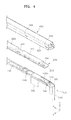
- FIG. 4 is an partial exploded perspective view of a portion IV of FIG. 3
- FIG. 5 is a cross-sectional view taken along a line V-V of FIG. 3 .
- the protective circuit module 200 may be disposed on the battery unit 100, and the upper cover 400 may be disposed on the protective circuit module 200.
- the protective circuit module 200 may be placed on the cap plate 120 on which the electrode pin 122 is formed.
- the first and second electrode tabs 131 and 132 included in each battery unit 100 may be inserted into the connection holes 241 formed in the protective circuit module 200 and then the first and second electrode tabs 131 and 132 and the protective circuit module may be soldered together.
- the first and second electrode tabs 131 and 132 may be electrically connected to the protective circuit module 200.
- the upper cover 400 may be combined with the battery unit 100 such that the protective circuit module 200 is interposed between the battery unit 100 and the upper cover 400.
- the upper cover 400 may include the hole 405, and the holder 140 of the battery unit 100 may include the protrusion 145.
- the protrusion 145 may be combined with the hole 405 through an interference fit such that the upper cover 400 and the holder 140 are combined with each other.
- the protrusion 145 may extend and protrude from the battery unit 100 along the thickness direction (y-direction) of the battery unit 100 and thus may be combinable with the hole 405 of the upper cover 400.
- embodiments of the invention can provide battery pack, comprising: a plurality of battery units that are arranged side by side along a first direction; a connection member arranged to connect the battery units in series, in parallel, or in series and parallel, the connection member being adjacent to a first surface of each battery unit of the plurality of battery units; a first cap arranged to accommodate the connection member, wherein first portions of all of the battery units are inserted into the first cap; a second cap that is spaced apart from the first cap by a predetermined gap, wherein second portions of all of the battery units are inserted into the second cap; and a label that at least partially surrounds the battery units exposed between the first cap and the second cap, wherein the first cap and the second cap fix an arrangement of the battery units.
- the first cap is arranged on the connection member.
- the first cap is an upper cap and upper portions of all of the battery units being inserted into the first cap
- the second cap is a lower cap and lower portions of all of the battery units being inserted into the second cap.
- connection member may be a protective circuit module.
- the first cap is arranged to be attached to a portion of the battery units, for example via an interference fit. As discussed, this may be a holder in some embodiments.
Landscapes
- Chemical & Material Sciences (AREA)
- Chemical Kinetics & Catalysis (AREA)
- Electrochemistry (AREA)
- General Chemical & Material Sciences (AREA)
- Engineering & Computer Science (AREA)
- Manufacturing & Machinery (AREA)
- Microelectronics & Electronic Packaging (AREA)
- Battery Mounting, Suspending (AREA)
- Secondary Cells (AREA)
- Connection Of Batteries Or Terminals (AREA)
Abstract
Description
- One or more embodiments relate to a battery pack.
- Use of portable computers that operate based on internal power supplied from batteries has dramatically increased due to the development of wireless communication technologies such as the Internet. In general, since the portable computers are small and easy to carry, that is, have high mobility, the portable computers are widely used for business or personal purposes in various places. As the portable computers include battery packs, they may be used irrespective of the area of use and connection to land power sources. A battery pack may include a plurality of battery units that may be repeatedly charged/discharged so as to provide sufficient output.
- Embodiments are directed to a battery pack including a plurality of battery units that are side by side along a first direction, a connection member that connects the battery units in series, in parallel, or in series and parallel, the connection member being adjacent to one surface of each battery unit of the plurality of battery units, an upper cap on and accommodating the connection member, upper portions of all of the battery units being inserted into the upper cap, a lower cap that is spaced apart from the upper cap by a predetermined gap, lower portions of all of the battery units being inserted into the lower cap, and a label that at least partially surrounds the battery units exposed between the upper cap and the lower cap. The upper cap and the lower cap fix an arrangement of the battery units.
- Each of the battery units may include sides that are perpendicular to the one surface. The sides may include a pair of first sides, the first sides of each battery unit being side by side with the first sides of the other battery units, and a pair of second sides that connect the pair of first sides to each other, the second sides having a smaller width than the first sides. The plurality of battery units may be arranged such that the second sides of adjacent battery units face each other.
- The battery pack may further include a spacer between the second sides of adjacent battery units that face each other.
- The spacer may include a first portion that insulates the second sides of the adjacent battery units from each other and a second portion that extends from the first portion to the connection member and supports the connection member.
- At least one of the upper cap and the lower cap may include a skirt portion that extends toward the pair of first sides. The label may be attached to the skirt portion.
- The battery pack may further include an insulating film between at least one of the pair of first sides and the label.
- Each battery unit may include a can that accommodates an electrode assembly and a cap plate that is combined with the can, the cap plate forming the one surface. Each battery unit may include an electrode pin located on the cap plate, the electrode pin being insulated from the cap plate.
- Each battery unit may include a holder on the cap plate, the holder accommodating a temperature-sensing element connected to the electrode pin.
- The connection member may be electrically connected to the electrode pin and the cap plate.
- The connection member may include circuit boards and protective elements mounted on the circuit boards.
- The holder may be coupleable with the upper cap.
- One of the holder and the upper cap may include a protrusion that protrudes in a direction perpendicular to the first direction, and the other one of the holder and the upper cap may include a hole that is coupleable with the protrusion.
- According to an aspect of the invention, there is provided a battery pack as set out in
claim 1. Preferred features are set out in claims 2 to 15. - Features will become apparent to those of skill in the art by describing in detail exemplary embodiments with reference to the attached drawings in which:
-
FIG. 1 illustrates a schematic perspective view of a battery pack according to an embodiment; -
FIG. 2 illustrates an exploded perspective view of one of a plurality of battery units illustrated inFIG. 1 ; -
FIG. 3 illustrates a perspective view depicting a state in which battery units, a protective circuit module, an upper cover, and a lower cover illustrated inFIG. 1 are assembled; -
FIG. 4 illustrates an exploded perspective view of a portion IV ofFIG. 3 ; and -
FIG. 5 illustrates a cross-sectional view taken along a line V-V ofFIG. 3 . - Example embodiments will now be described more fully hereinafter with reference to the accompanying drawings; however, they may be embodied in different forms and should not be construed as limited to the embodiments set forth herein. Rather, these embodiments are provided so that this disclosure will be thorough and complete, and will fully convey exemplary implementations to those skilled in the art.
- In the drawing figures, the dimensions of layers and regions may be exaggerated for clarity of illustration. Like reference numerals refer to like elements throughout.
-
FIG. 1 is a schematic perspective view of a battery pack according to an embodiment,FIG. 2 is an perspective view of one of a plurality of battery units and a holder illustrated inFIG. 1 , andFIG. 3 is a perspective view illustrating a state in which a plurality ofbattery units 100, aprotective circuit module 200, anupper cover 400, and alower cover 500 are assembled. InFIG. 3 , alabel 600 and aninsulating film 700 are omitted inFIG. 3 for convenience of explanation. - The
upper cover 400 is an example of a first cap, and thelower cover 500 is an example of a second cap. - Referring to
FIGS. 1 through 3 , the battery pack according to the current embodiment may include the plurality ofbattery units 100, theprotective circuit module 200, which is electrically connected to each of the plurality ofbattery units 100, aspacer 300 that electrically insulates thebattery units 100 from each other, theupper cover 400, thelower cover 500, thelabel 600, and theinsulating film 700. - The plurality of
battery units 100 may be disposed side by side along a first direction (x-direction). For example, the plurality ofbattery units 100 may be disposed side by side so that their top surfaces are in the same direction. Sides ofadjacent battery units 100 may face each other. Each of thebattery units 100 may be a lithium-ion battery, that is, a secondary battery that may be recharged. - Referring to
FIG. 2 , each of thebattery units 100 may include a bare cell B and aholder 140 fixed to an upper portion of the bare cell B. - The bare cell B may include a
can 110 having an opening formed therein, anelectrode assembly 104 accommodated in thecan 110 through the opening, acap plate 120 that seals the opening of thecan 110, and anelectrode pin 122 formed on thecap plate 120. - The
can 110 may have an opened, approximately hexahedral top surface and may be manufactured of a metallic material so as have a suitable resistance. For example, thecan 110 may be manufactured of aluminum (Al) or an Al alloy. After theelectrode assembly 104 is inserted into thecan 110 through the opening, the opening may be sealed by thecap plate 120. Like thecan 110, thecap plate 120 may be manufactured of a metallic material, such as aluminum or an Al alloy. Portions at which thecap plate 120 and the can 110 contact each other may be combined with each other through laser welding so that an internal air-tight state of the bare cell B may be maintained. - The
electrode assembly 104 may include a first electrode plate 101 and asecond electrode plate 102 onto which an electrode active material is coated, and aseparator 103 interposed therebetween. The first electrode plate 101 and thesecond electrode plate 102 may have different polarities. Theelectrode assembly 104 may be manufactured in such a way that the first electrode plate101, theseparator 103, and thesecond electrode plate 102 may be sequentially stacked on theelectrode assembly 104 and then be wound in a jelly roll shape. In other implementations, theelectrode assembly 104 may be a stack structure where the first electrode plate 101, theseparator 103, and thesecond electrode plate 102 are sequentially stacked. - The
electrode pin 122 may be formed on thecap plate 120. The first electrode plate 101 may be electrically connected to thecap plate 120, and thesecond electrode plate 102 may be electrically connected to theelectrode pin 122. The first electrode plate 101 and thesecond electrode plate 102 may have different polarities. Accordingly, theelectrode pin 122 and thecap plate 120 may have different polarities. For example, theelectrode pin 122 may have a negative electrode polarity, and thecap plate 120 may have a positive electrode polarity. Agasket 125 may be provided between theelectrode pin 122 and thecap plate 120 so as to prevent a short circuit between theelectrode pin 122 and thecap plate 120. Thegasket 125 may be manufactured of an insulating material and may prevent an electrical short circuit between theelectrode pin 122 and thecap plate 120. - The
battery unit 100 may include first andsecond electrode tabs second electrode tabs - For example, the
first electrode tab 131 may be disposed on thecap plate 120 and may be electrically connected to thecap plate 120. When thecap plate 120 has a positive electrode polarity, thefirst electrode tab 131 welded onto thecap plate 120 may also have a positive electrode polarity. - The
second electrode tab 132 may be connected to theelectrode pin 122 and a temperature-sensing element, such as a temperature cut off (TCO). For example, thesecond electrode tab 132 may include afirst portion 132a and asecond portion 132b. One end of thefirst portion 132a may be connected to theelectrode pin 122, and the other end of thefirst portion 132a may be connected to the temperature-sensing element. One end of thesecond portion 132b may be connected to the temperature-sensing element so that thesecond electrode tab 132 including the temperature-sensing element may be electrically connected to theelectrode pin 122. - The first and
second electrode tabs cap plate 120. Since thecap plate 120 has a positive electrode polarity, as described above, an electrical short circuit between thecap plate 120 and thesecond electrode tab 132 having a negative electrode polarity could occur easily. Thus, thesecond electrode tab 132 may be disposed on theholder 140 put on thecap plate 120. - The
holder 140 may accommodate thesecond electrode tab 132 and the temperature-sensing element. Theholder 140 may include an opening op formed in a position corresponding to a position of the temperature-sensing element so as to sensitively react to a change in temperature of thebattery unit 100. - The
holder 140 may be fixed onto thebattery unit 100 using a fixing member, such as atape 150, while accommodating thesecond electrode tab 132 and the temperature-sensing element. - The
holder 140 may include aprotrusion 145. Theprotrusion 145 may extend and protrude from theholder 140 along a thickness direction (y-direction) of thebattery unit 100 and may be combined with ahole 405 formed in theupper cover 400 that will be described below. For example, theprotrusion 145 of theholder 140 may be combined with thehole 405 of theupper cover 400 through interference fit. - In the current embodiment, the
protrusion 145 is formed on theholder 140, and thehole 405 is formed in theupper cover 400. In other implementations, a hole may be formed in theholder 140, and a protrusion may be formed on theupper cover 400 so that the protrusion and the hole may be combined with each other through an interference fit. Considering the overall thickness of the battery pack, for example, theprotrusion 145 may be formed on theholder 140 and thehole 405 may be formed in theupper cover 400, such that the thickness of the battery pack may be reduced. - Referring back to
FIGS. 1 through 3 , theprotective circuit module 200 may be disposed on a top surface of eachbattery unit 100, for example, on thecap plate 120, and may be electrically connected to thebattery unit 100 such that charging/discharging of thebattery unit 100 may be controlled. Theprotective circuit module 200 may prevent overheating and explosion that occur due to overcharging, overdischarging, or overcurrent of thebattery unit 100. - The
protective circuit module 200 may includecircuit boards 210,protective elements 220 mounted on thecircuit boards 210, andexternal terminals 230. Thecircuit boards 210 may extend long along an arrangement direction of the plurality ofbattery units 100. Theprotective elements 220 may be one selected from the group of safety elements including passive elements, such as resistors and capacitors of thecircuit boards 210, or active elements, such as field effect transistors (FETs), or integrated circuits (ICs). - Each of the
circuit boards 210 may include aconnection hole 241. The first andsecond electrode tabs battery units 100 may be inserted into theconnection hole 241 formed in eachcircuit board 210. The first andsecond electrode tabs respective circuit board 210 may be soldered together. Patterns through which thebattery units 100 may be connected in series and/or in parallel, may be formed on thecircuit board 210. The first andsecond electrode tabs battery unit 100 may be directly connected to theconnection hole 241 formed in thecircuit board 210 such that the plurality ofbattery units 100 may be charge/discharge-controlled according to driving of theprotective element 220 and simultaneously may be connected in series and/or in parallel. - The
spacer 300 may be interposed betweenadjacent battery units 100. One end of thespacer 300 may extend toward theprotective circuit module 200 so as to support theprotective circuit module 200. For example, thespacer 300 may include afirst portion 310 interposed between theadjacent battery units 100, and asecond portion 320 that extends from thefirst portion 310 to theprotective circuit module 200. - The
first portion 310 of thespacer 300 may electrically insulate theadjacent battery units 100 from each other. As described above with reference toFIG. 2 , thecan 110 and thecap plate 120 of thebattery unit 100 may be manufactured of a metallic material, and thecan 110 may be welded to thecap plate 120 such that thecan 110 may have the same polarity as that of thecap plate 120. When thebattery units 100 are disposed side by side, as illustrated inFIG. 1 , an undesired electrical connection between theadjacent battery units 100 could be formed. According to an embodiment, thefirst portion 310 of thespacer 300 may be interposed between theadjacent battery units 100. Accordingly, an undesired electrical connection between theadjacent battery units 100 may be prevented. - The
second portion 320 of thespacer 300 may be interposed in a space (or a gap) between theprotective circuit module 200 and thebattery unit 100 and may support theprotective circuit module 200. Thebattery unit 100 may include theelectrode pin 122 that protrudes upward and theholder 140 may be interposed on thebattery unit 100. Accordingly, a space may be formed between the top surface of thebattery unit 100 and a bottom surface of theprotective circuit module 200. When thesecond portion 320 of thespacer 300 is interposed in the space, theprotective circuit module 200 may be supported and simultaneously may be protected from an external force applied to theprotective circuit module 200. - The
upper cover 400 may be disposed on theprotective circuit module 200. Theupper cover 400 may include anopening 410 through which theexternal terminal 230 formed on theprotective circuit module 200 is exposed. - The
upper cover 400 may have a length that is substantially the same as the entire length of the plurality ofbattery units 100 disposed side by side along the first direction. Theupper cover 400 may be combined with thebattery units 100 such that theprotective circuit module 200 may be interposed between thebattery units 100. For example, theupper cover 400 and theholder 140 provided at each of thebattery units 100 may be combined with each other through an interference fit, as described above. - The
lower cover 500 may be disposed at an opposite side to a side at which theupper cover 400 is disposed, so as to face theupper cover 400. Theupper cover 400 may be disposed to cover the top surface of eachbattery unit 100, with theprotective circuit module 200 being interposed between thebattery units 100. Thelower cover 500 may be disposed to cover the bottom surface of eachbattery unit 100. - The
label 600 may be disposed to surround sides of eachbattery unit 100. For example, thelabel 600 may be attached to the sides of thebattery unit 100. An insulatingfilm 700 may be interposed between thelabel 600 and the sides of thebattery unit 100. - Portions of the
label 600 may be attached to theupper cover 400 and thelower cover 500. To this end,skirt portions upper cover 400 and thelower cover 500 and may extend toward thebattery unit 100. The portions of thelabel 600 may be attached onto theskirt portions upper cover 400, thelower cover 500, and thelabel 600 may be insulated from thebattery unit 100 and simultaneously, such that thebattery unit 100 may be prevented from being exposed to the outside. - Hereinafter, a combination of the
upper cover 400 and thebattery unit 100, for example, a combination of theupper cover 400 and theholder 140 of thebattery unit 100 will be descried with reference toFIGS. 4 and5 . -
FIG. 4 is an partial exploded perspective view of a portion IV ofFIG. 3 , andFIG. 5 is a cross-sectional view taken along a line V-V ofFIG. 3 . - Referring to
FIGS. 4 and5 , theprotective circuit module 200 may be disposed on thebattery unit 100, and theupper cover 400 may be disposed on theprotective circuit module 200. Theprotective circuit module 200 may be placed on thecap plate 120 on which theelectrode pin 122 is formed. The first andsecond electrode tabs battery unit 100 may be inserted into the connection holes 241 formed in theprotective circuit module 200 and then the first andsecond electrode tabs second electrode tabs protective circuit module 200. - The
upper cover 400 may be combined with thebattery unit 100 such that theprotective circuit module 200 is interposed between thebattery unit 100 and theupper cover 400. For example, theupper cover 400 may include thehole 405, and theholder 140 of thebattery unit 100 may include theprotrusion 145. Theprotrusion 145 may be combined with thehole 405 through an interference fit such that theupper cover 400 and theholder 140 are combined with each other. Theprotrusion 145 may extend and protrude from thebattery unit 100 along the thickness direction (y-direction) of thebattery unit 100 and thus may be combinable with thehole 405 of theupper cover 400. - As discussed, embodiments of the invention can provide battery pack, comprising: a plurality of battery units that are arranged side by side along a first direction; a connection member arranged to connect the battery units in series, in parallel, or in series and parallel, the connection member being adjacent to a first surface of each battery unit of the plurality of battery units; a first cap arranged to accommodate the connection member, wherein first portions of all of the battery units are inserted into the first cap; a second cap that is spaced apart from the first cap by a predetermined gap, wherein second portions of all of the battery units are inserted into the second cap; and a label that at least partially surrounds the battery units exposed between the first cap and the second cap, wherein the first cap and the second cap fix an arrangement of the battery units.
- In some embodiments, the first cap is arranged on the connection member.
- In some embodiments, the first cap is an upper cap and upper portions of all of the battery units being inserted into the first cap, and the second cap is a lower cap and lower portions of all of the battery units being inserted into the second cap.
- In some embodiments, the connection member may be a protective circuit module.
- In some embodiments, the first cap is arranged to be attached to a portion of the battery units, for example via an interference fit. As discussed, this may be a holder in some embodiments.
- As described above, according to the one or more of the above embodiments provide a compact battery pack having improved assembling characteristics may be provided.
- Example embodiments have been disclosed herein, and although specific terms are employed, they are used and are to be interpreted in a generic and descriptive sense only and not for purpose of limitation. Accordingly, it will be understood by those of skill in the art that various changes in form and details may be made without departing from the scope as set forth in the following claims.
Claims (15)
- A battery pack, comprising:a plurality of battery units that are arranged side by side along a first direction;a connection member arranged to connect the battery units in series, in parallel, or in series and parallel, the connection member being adjacent to a first surface of each battery unit of the plurality of battery units;a first cap arranged to accommodate the connection member, wherein first portions of all of the battery units are inserted into the first cap;a second cap that is spaced apart from the first cap by a predetermined gap,
wherein second portions of all of the battery units are inserted into the second cap; anda label that at least partially surrounds the battery units exposed between the first cap and the second cap,wherein the first cap and the second cap fix an arrangement of the battery units. - The battery pack of claim 1, wherein the first cap is arranged on the connection member.
- The battery pack of claim 1 or 2, wherein the first cap is an upper cap and upper portions of all of the battery units being inserted into the first cap, and the second cap is a lower cap and lower portions of all of the battery units being inserted into the second cap.
- The battery pack of any one of claims 1 to 3, wherein:each of the battery units includes sides that are perpendicular to the first surface,the sides include a pair of first sides, the first sides of each battery unit being side by side with the first sides of all other battery units, and a pair of second sides that connect the pair of first sides to each other, the second sides having a smaller width than the first sides, andthe plurality of battery units are arranged such that the second sides of each of adjacent battery units face each other.
- The battery pack of claim 4, further comprising a spacer between the second sides of adjacent battery units that face each other.
- The battery pack of claim 5, wherein the spacer includes a first portion arranged to insulate the second sides of the adjacent battery units from each other and a second portion that extends from the first portion to the connection member and is arranged to support the connection member.
- The battery pack of any one of claims 4 to 6, wherein at least one of the first cap and the second cap includes a skirt portion that extends toward the pair of first sides, and
the label is attached to the skirt portion. - The battery pack of claim 7, further comprising an insulating film between at least one of the pair of first sides and the label.
- The battery pack of any one of claims 1 to 8, wherein:each battery unit includes a can that accommodates an electrode assembly and a cap plate that is combined with the can, the cap plate forming the first surface, andeach battery unit includes an electrode pin located on the cap plate, the electrode pin being insulated from the cap plate.
- The battery pack of claim 9, wherein each battery unit includes a holder on the cap plate, the holder accommodating a temperature-sensing element connected to the electrode pin.
- The battery pack of claim 9 or 10, wherein the connection member is electrically connected to the electrode pin and the cap plate.
- The battery pack of claim 11, wherein the connection member includes circuit boards and protective elements mounted on the circuit boards.
- The battery pack of any one of claims 10 to 12, wherein the holder is coupleable with the first cap.
- The battery pack of claim 13, wherein one of the holder and the first cap includes a protrusion that protrudes in a direction perpendicular to the first direction, and the other one of the holder and the upper cap includes a hole that is coupleable with the protrusion.
- The battery pack of any one of claims 1 to 14, wherein the connection member is a protective circuit module.
Applications Claiming Priority (1)
| Application Number | Priority Date | Filing Date | Title |
|---|---|---|---|
| KR1020140015641A KR101520391B1 (en) | 2014-02-11 | 2014-02-11 | Battery Pack |
Publications (2)
| Publication Number | Publication Date |
|---|---|
| EP2905824A1 true EP2905824A1 (en) | 2015-08-12 |
| EP2905824B1 EP2905824B1 (en) | 2018-05-23 |
Family
ID=51626452
Family Applications (1)
| Application Number | Title | Priority Date | Filing Date |
|---|---|---|---|
| EP14187160.8A Active EP2905824B1 (en) | 2014-02-11 | 2014-09-30 | Battery pack |
Country Status (5)
| Country | Link |
|---|---|
| US (2) | US9257691B2 (en) |
| EP (1) | EP2905824B1 (en) |
| JP (1) | JP5725246B1 (en) |
| KR (1) | KR101520391B1 (en) |
| CN (1) | CN104835979B (en) |
Families Citing this family (11)
| Publication number | Priority date | Publication date | Assignee | Title |
|---|---|---|---|---|
| EP4060704A1 (en) | 2015-08-03 | 2022-09-21 | Panasonic Intellectual Property Management Co., Ltd. | Electromagnetic relay |
| KR102619723B1 (en) * | 2016-04-14 | 2023-12-28 | 삼성에스디아이 주식회사 | Battery pack |
| KR102248230B1 (en) | 2017-12-07 | 2021-05-03 | 주식회사 엘지화학 | Secondary battery module |
| KR102656440B1 (en) * | 2019-02-01 | 2024-04-09 | 주식회사 엘지에너지솔루션 | Battery module |
| JP1667632S (en) * | 2019-07-05 | 2020-09-07 | ||
| JP1667633S (en) * | 2019-07-05 | 2020-09-07 | ||
| JP1667618S (en) * | 2019-07-05 | 2020-09-07 | ||
| JP1667617S (en) * | 2019-07-05 | 2020-09-07 | ||
| CN210073989U (en) | 2019-08-23 | 2020-02-14 | 宁德时代新能源科技股份有限公司 | battery module |
| CN112820992B (en) * | 2019-11-15 | 2023-11-21 | 东莞新能德科技有限公司 | Battery and manufacturing method |
| CN111916602B (en) * | 2020-08-05 | 2022-12-06 | 东莞新能德科技有限公司 | Battery and method for manufacturing same |
Citations (5)
| Publication number | Priority date | Publication date | Assignee | Title |
|---|---|---|---|---|
| JPH11135088A (en) * | 1997-10-30 | 1999-05-21 | Toshiba Battery Co Ltd | Secondary battery pack |
| EP2109166A1 (en) * | 2008-04-11 | 2009-10-14 | Samsung SDI Co., Ltd. | Battery pack |
| US20100143785A1 (en) * | 2008-12-05 | 2010-06-10 | Samsung Sdi Co., Ltd. | Battery pack |
| US20120214026A1 (en) * | 2011-02-17 | 2012-08-23 | Dae-Yon Moon | Battery pack |
| WO2013187687A1 (en) * | 2012-06-12 | 2013-12-19 | Sk Innovation Co.,Ltd. | Easily assembled secondary battery module |
Family Cites Families (28)
| Publication number | Priority date | Publication date | Assignee | Title |
|---|---|---|---|---|
| US4061955A (en) * | 1976-05-19 | 1977-12-06 | The United States Of America As Represented By The Administrator Of The National Aeronautics And Space Administration | Multi-cell battery protection system |
| US4738906A (en) * | 1985-04-30 | 1988-04-19 | Weather Ready Inc. | Storage battery heating and heat maintenance apparatus |
| US4871553A (en) * | 1988-10-27 | 1989-10-03 | Eveready Battery Company, Inc. | Cell circuit interrupter |
| US6403251B1 (en) * | 2000-01-31 | 2002-06-11 | Moltech Power Systems, Inc | Battery pack with multiple secure modules |
| US6729908B2 (en) * | 2001-07-31 | 2004-05-04 | Delphi Technologies, Inc. | Battery pack having perforated terminal arrangement |
| US7338733B2 (en) * | 2002-04-30 | 2008-03-04 | Sanyo Electric Co., Ltd. | Battery pack |
| JP4430075B2 (en) | 2003-10-14 | 2010-03-10 | エルジー・ケム・リミテッド | Cartridge type lithium ion polymer battery pack |
| JP2006040623A (en) * | 2004-07-23 | 2006-02-09 | Sony Corp | Battery pack |
| KR100801635B1 (en) * | 2004-11-02 | 2008-02-05 | 주식회사 엘지화학 | Member for measuring battery voltage and temperature of battery pack |
| KR100857021B1 (en) * | 2004-12-10 | 2008-09-05 | 주식회사 엘지화학 | Rechargeable Battery Pack |
| WO2006126379A1 (en) | 2005-05-25 | 2006-11-30 | Hitachi Maxell, Ltd. | Battery pack |
| KR100833739B1 (en) * | 2006-10-27 | 2008-05-29 | 삼성에스디아이 주식회사 | Square Lithium Ion Battery |
| KR100878285B1 (en) * | 2007-06-05 | 2009-01-12 | 삼성에스디아이 주식회사 | Battery pack |
| KR100876266B1 (en) | 2007-09-28 | 2008-12-26 | 삼성에스디아이 주식회사 | Secondary battery |
| KR100998301B1 (en) * | 2007-11-08 | 2010-12-03 | 삼성에스디아이 주식회사 | Battery pack and electronic device having same |
| JP5493301B2 (en) | 2008-06-30 | 2014-05-14 | 住友化学株式会社 | Sodium secondary battery |
| KR101030876B1 (en) * | 2008-11-19 | 2011-04-22 | 삼성에스디아이 주식회사 | Battery pack |
| KR101023849B1 (en) | 2009-01-09 | 2011-03-22 | 삼성에스디아이 주식회사 | Secondary battery with protection circuit module |
| KR101023886B1 (en) | 2009-02-17 | 2011-03-22 | 삼성에스디아이 주식회사 | Secondary battery with protection circuit module |
| US9263724B2 (en) * | 2009-10-12 | 2016-02-16 | Samsung Sdi Co., Ltd. | Battery pack |
| KR200466244Y1 (en) | 2010-01-29 | 2013-04-05 | 주식회사 이랜텍 | A battery pack involving protection circuit module within safty device |
| KR101136310B1 (en) * | 2010-06-07 | 2012-04-19 | 에스비리모티브 주식회사 | Battery pack |
| US9451710B2 (en) | 2010-08-26 | 2016-09-20 | Samsung Sdi Co., Ltd. | Battery pack |
| JP5646297B2 (en) * | 2010-11-25 | 2014-12-24 | 三洋電機株式会社 | Pack battery |
| KR101234242B1 (en) * | 2011-02-17 | 2013-02-18 | 삼성에스디아이 주식회사 | Battery Pack |
| KR101234241B1 (en) | 2011-02-17 | 2013-02-18 | 삼성에스디아이 주식회사 | Rechargeable Battery pack |
| KR101255250B1 (en) * | 2012-03-23 | 2013-04-16 | 삼성에스디아이 주식회사 | Battery module |
| KR101493829B1 (en) * | 2014-03-27 | 2015-02-16 | 삼성에스디아이 주식회사 | Battery Pack |
-
2014
- 2014-02-11 KR KR1020140015641A patent/KR101520391B1/en active Active
- 2014-08-05 US US14/451,958 patent/US9257691B2/en active Active
- 2014-09-30 EP EP14187160.8A patent/EP2905824B1/en active Active
- 2014-10-15 CN CN201410545135.6A patent/CN104835979B/en active Active
- 2014-10-17 JP JP2014212246A patent/JP5725246B1/en active Active
-
2016
- 2016-02-04 US US15/015,218 patent/US9653760B2/en active Active
Patent Citations (5)
| Publication number | Priority date | Publication date | Assignee | Title |
|---|---|---|---|---|
| JPH11135088A (en) * | 1997-10-30 | 1999-05-21 | Toshiba Battery Co Ltd | Secondary battery pack |
| EP2109166A1 (en) * | 2008-04-11 | 2009-10-14 | Samsung SDI Co., Ltd. | Battery pack |
| US20100143785A1 (en) * | 2008-12-05 | 2010-06-10 | Samsung Sdi Co., Ltd. | Battery pack |
| US20120214026A1 (en) * | 2011-02-17 | 2012-08-23 | Dae-Yon Moon | Battery pack |
| WO2013187687A1 (en) * | 2012-06-12 | 2013-12-19 | Sk Innovation Co.,Ltd. | Easily assembled secondary battery module |
Also Published As
| Publication number | Publication date |
|---|---|
| US9653760B2 (en) | 2017-05-16 |
| JP5725246B1 (en) | 2015-05-27 |
| JP2015153749A (en) | 2015-08-24 |
| US9257691B2 (en) | 2016-02-09 |
| CN104835979B (en) | 2021-02-05 |
| US20150228954A1 (en) | 2015-08-13 |
| EP2905824B1 (en) | 2018-05-23 |
| KR101520391B1 (en) | 2015-05-14 |
| US20160156072A1 (en) | 2016-06-02 |
| CN104835979A (en) | 2015-08-12 |
Similar Documents
| Publication | Publication Date | Title |
|---|---|---|
| EP2905824B1 (en) | Battery pack | |
| KR101925934B1 (en) | Battery pack | |
| EP2043177B1 (en) | Protective circuit board and battery pack using the same | |
| KR101483131B1 (en) | Battery Pack | |
| US11411256B2 (en) | Battery pack | |
| US9515303B2 (en) | Battery pack | |
| KR101985762B1 (en) | RECHARGEABLE BATTERY With Improved Connection Structure of Terminal AND BATTERY MODULE Comprising the Same | |
| KR20140097731A (en) | Battery Pack | |
| EP3016171B1 (en) | Secondary battery and secondary battery pack including the same | |
| KR101397025B1 (en) | Lead tab assembly and battery module with the same | |
| KR20160123788A (en) | Battery pack | |
| KR20170117756A (en) | Battery pack | |
| KR20160056691A (en) | Rechargeable battery | |
| US20150228960A1 (en) | Battery pack | |
| CN105990601B (en) | Battery | |
| KR101648891B1 (en) | Battery Pack | |
| KR101483130B1 (en) | Battery Pack | |
| KR20150094487A (en) | Battery Pack |
Legal Events
| Date | Code | Title | Description |
|---|---|---|---|
| PUAI | Public reference made under article 153(3) epc to a published international application that has entered the european phase |
Free format text: ORIGINAL CODE: 0009012 |
|
| AK | Designated contracting states |
Kind code of ref document: A1 Designated state(s): AL AT BE BG CH CY CZ DE DK EE ES FI FR GB GR HR HU IE IS IT LI LT LU LV MC MK MT NL NO PL PT RO RS SE SI SK SM TR |
|
| AX | Request for extension of the european patent |
Extension state: BA ME |
|
| 17P | Request for examination filed |
Effective date: 20160212 |
|
| RBV | Designated contracting states (corrected) |
Designated state(s): AL AT BE BG CH CY CZ DE DK EE ES FI FR GB GR HR HU IE IS IT LI LT LU LV MC MK MT NL NO PL PT RO RS SE SI SK SM TR |
|
| 17Q | First examination report despatched |
Effective date: 20160613 |
|
| STAA | Information on the status of an ep patent application or granted ep patent |
Free format text: STATUS: EXAMINATION IS IN PROGRESS |
|
| GRAP | Despatch of communication of intention to grant a patent |
Free format text: ORIGINAL CODE: EPIDOSNIGR1 |
|
| STAA | Information on the status of an ep patent application or granted ep patent |
Free format text: STATUS: GRANT OF PATENT IS INTENDED |
|
| RIC1 | Information provided on ipc code assigned before grant |
Ipc: H01M 2/20 20060101ALI20171110BHEP Ipc: H01M 2/10 20060101AFI20171110BHEP Ipc: H01M 10/48 20060101ALN20171110BHEP Ipc: H01M 10/42 20060101ALN20171110BHEP |
|
| INTG | Intention to grant announced |
Effective date: 20171214 |
|
| GRAS | Grant fee paid |
Free format text: ORIGINAL CODE: EPIDOSNIGR3 |
|
| GRAA | (expected) grant |
Free format text: ORIGINAL CODE: 0009210 |
|
| STAA | Information on the status of an ep patent application or granted ep patent |
Free format text: STATUS: THE PATENT HAS BEEN GRANTED |
|
| AK | Designated contracting states |
Kind code of ref document: B1 Designated state(s): AL AT BE BG CH CY CZ DE DK EE ES FI FR GB GR HR HU IE IS IT LI LT LU LV MC MK MT NL NO PL PT RO RS SE SI SK SM TR |
|
| RAP1 | Party data changed (applicant data changed or rights of an application transferred) |
Owner name: SAMSUNG SDI CO., LTD. |
|
| REG | Reference to a national code |
Ref country code: GB Ref legal event code: FG4D |
|
| REG | Reference to a national code |
Ref country code: CH Ref legal event code: EP |
|
| REG | Reference to a national code |
Ref country code: IE Ref legal event code: FG4D |
|
| REG | Reference to a national code |
Ref country code: AT Ref legal event code: REF Ref document number: 1002218 Country of ref document: AT Kind code of ref document: T Effective date: 20180615 |
|
| REG | Reference to a national code |
Ref country code: DE Ref legal event code: R096 Ref document number: 602014025789 Country of ref document: DE |
|
| REG | Reference to a national code |
Ref country code: FR Ref legal event code: PLFP Year of fee payment: 5 |
|
| REG | Reference to a national code |
Ref country code: NL Ref legal event code: MP Effective date: 20180523 |
|
| REG | Reference to a national code |
Ref country code: LT Ref legal event code: MG4D |
|
| PG25 | Lapsed in a contracting state [announced via postgrant information from national office to epo] |
Ref country code: ES Free format text: LAPSE BECAUSE OF FAILURE TO SUBMIT A TRANSLATION OF THE DESCRIPTION OR TO PAY THE FEE WITHIN THE PRESCRIBED TIME-LIMIT Effective date: 20180523 Ref country code: LT Free format text: LAPSE BECAUSE OF FAILURE TO SUBMIT A TRANSLATION OF THE DESCRIPTION OR TO PAY THE FEE WITHIN THE PRESCRIBED TIME-LIMIT Effective date: 20180523 Ref country code: NO Free format text: LAPSE BECAUSE OF FAILURE TO SUBMIT A TRANSLATION OF THE DESCRIPTION OR TO PAY THE FEE WITHIN THE PRESCRIBED TIME-LIMIT Effective date: 20180823 Ref country code: SE Free format text: LAPSE BECAUSE OF FAILURE TO SUBMIT A TRANSLATION OF THE DESCRIPTION OR TO PAY THE FEE WITHIN THE PRESCRIBED TIME-LIMIT Effective date: 20180523 Ref country code: FI Free format text: LAPSE BECAUSE OF FAILURE TO SUBMIT A TRANSLATION OF THE DESCRIPTION OR TO PAY THE FEE WITHIN THE PRESCRIBED TIME-LIMIT Effective date: 20180523 Ref country code: BG Free format text: LAPSE BECAUSE OF FAILURE TO SUBMIT A TRANSLATION OF THE DESCRIPTION OR TO PAY THE FEE WITHIN THE PRESCRIBED TIME-LIMIT Effective date: 20180823 |
|
| PG25 | Lapsed in a contracting state [announced via postgrant information from national office to epo] |
Ref country code: GR Free format text: LAPSE BECAUSE OF FAILURE TO SUBMIT A TRANSLATION OF THE DESCRIPTION OR TO PAY THE FEE WITHIN THE PRESCRIBED TIME-LIMIT Effective date: 20180824 Ref country code: RS Free format text: LAPSE BECAUSE OF FAILURE TO SUBMIT A TRANSLATION OF THE DESCRIPTION OR TO PAY THE FEE WITHIN THE PRESCRIBED TIME-LIMIT Effective date: 20180523 Ref country code: LV Free format text: LAPSE BECAUSE OF FAILURE TO SUBMIT A TRANSLATION OF THE DESCRIPTION OR TO PAY THE FEE WITHIN THE PRESCRIBED TIME-LIMIT Effective date: 20180523 Ref country code: NL Free format text: LAPSE BECAUSE OF FAILURE TO SUBMIT A TRANSLATION OF THE DESCRIPTION OR TO PAY THE FEE WITHIN THE PRESCRIBED TIME-LIMIT Effective date: 20180523 Ref country code: HR Free format text: LAPSE BECAUSE OF FAILURE TO SUBMIT A TRANSLATION OF THE DESCRIPTION OR TO PAY THE FEE WITHIN THE PRESCRIBED TIME-LIMIT Effective date: 20180523 |
|
| REG | Reference to a national code |
Ref country code: AT Ref legal event code: MK05 Ref document number: 1002218 Country of ref document: AT Kind code of ref document: T Effective date: 20180523 |
|
| PG25 | Lapsed in a contracting state [announced via postgrant information from national office to epo] |
Ref country code: SK Free format text: LAPSE BECAUSE OF FAILURE TO SUBMIT A TRANSLATION OF THE DESCRIPTION OR TO PAY THE FEE WITHIN THE PRESCRIBED TIME-LIMIT Effective date: 20180523 Ref country code: AT Free format text: LAPSE BECAUSE OF FAILURE TO SUBMIT A TRANSLATION OF THE DESCRIPTION OR TO PAY THE FEE WITHIN THE PRESCRIBED TIME-LIMIT Effective date: 20180523 Ref country code: DK Free format text: LAPSE BECAUSE OF FAILURE TO SUBMIT A TRANSLATION OF THE DESCRIPTION OR TO PAY THE FEE WITHIN THE PRESCRIBED TIME-LIMIT Effective date: 20180523 Ref country code: PL Free format text: LAPSE BECAUSE OF FAILURE TO SUBMIT A TRANSLATION OF THE DESCRIPTION OR TO PAY THE FEE WITHIN THE PRESCRIBED TIME-LIMIT Effective date: 20180523 Ref country code: EE Free format text: LAPSE BECAUSE OF FAILURE TO SUBMIT A TRANSLATION OF THE DESCRIPTION OR TO PAY THE FEE WITHIN THE PRESCRIBED TIME-LIMIT Effective date: 20180523 Ref country code: CZ Free format text: LAPSE BECAUSE OF FAILURE TO SUBMIT A TRANSLATION OF THE DESCRIPTION OR TO PAY THE FEE WITHIN THE PRESCRIBED TIME-LIMIT Effective date: 20180523 Ref country code: RO Free format text: LAPSE BECAUSE OF FAILURE TO SUBMIT A TRANSLATION OF THE DESCRIPTION OR TO PAY THE FEE WITHIN THE PRESCRIBED TIME-LIMIT Effective date: 20180523 |
|
| REG | Reference to a national code |
Ref country code: DE Ref legal event code: R097 Ref document number: 602014025789 Country of ref document: DE |
|
| PG25 | Lapsed in a contracting state [announced via postgrant information from national office to epo] |
Ref country code: IT Free format text: LAPSE BECAUSE OF FAILURE TO SUBMIT A TRANSLATION OF THE DESCRIPTION OR TO PAY THE FEE WITHIN THE PRESCRIBED TIME-LIMIT Effective date: 20180523 Ref country code: SM Free format text: LAPSE BECAUSE OF FAILURE TO SUBMIT A TRANSLATION OF THE DESCRIPTION OR TO PAY THE FEE WITHIN THE PRESCRIBED TIME-LIMIT Effective date: 20180523 |
|
| PLBE | No opposition filed within time limit |
Free format text: ORIGINAL CODE: 0009261 |
|
| STAA | Information on the status of an ep patent application or granted ep patent |
Free format text: STATUS: NO OPPOSITION FILED WITHIN TIME LIMIT |
|
| PG25 | Lapsed in a contracting state [announced via postgrant information from national office to epo] |
Ref country code: MC Free format text: LAPSE BECAUSE OF FAILURE TO SUBMIT A TRANSLATION OF THE DESCRIPTION OR TO PAY THE FEE WITHIN THE PRESCRIBED TIME-LIMIT Effective date: 20180523 |
|
| REG | Reference to a national code |
Ref country code: CH Ref legal event code: PL |
|
| 26N | No opposition filed |
Effective date: 20190226 |
|
| PG25 | Lapsed in a contracting state [announced via postgrant information from national office to epo] |
Ref country code: SI Free format text: LAPSE BECAUSE OF FAILURE TO SUBMIT A TRANSLATION OF THE DESCRIPTION OR TO PAY THE FEE WITHIN THE PRESCRIBED TIME-LIMIT Effective date: 20180523 |
|
| REG | Reference to a national code |
Ref country code: BE Ref legal event code: MM Effective date: 20180930 |
|
| REG | Reference to a national code |
Ref country code: IE Ref legal event code: MM4A |
|
| PG25 | Lapsed in a contracting state [announced via postgrant information from national office to epo] |
Ref country code: LU Free format text: LAPSE BECAUSE OF NON-PAYMENT OF DUE FEES Effective date: 20180930 |
|
| PG25 | Lapsed in a contracting state [announced via postgrant information from national office to epo] |
Ref country code: IE Free format text: LAPSE BECAUSE OF NON-PAYMENT OF DUE FEES Effective date: 20180930 |
|
| PG25 | Lapsed in a contracting state [announced via postgrant information from national office to epo] |
Ref country code: CH Free format text: LAPSE BECAUSE OF NON-PAYMENT OF DUE FEES Effective date: 20180930 Ref country code: LI Free format text: LAPSE BECAUSE OF NON-PAYMENT OF DUE FEES Effective date: 20180930 Ref country code: BE Free format text: LAPSE BECAUSE OF NON-PAYMENT OF DUE FEES Effective date: 20180930 |
|
| PG25 | Lapsed in a contracting state [announced via postgrant information from national office to epo] |
Ref country code: AL Free format text: LAPSE BECAUSE OF FAILURE TO SUBMIT A TRANSLATION OF THE DESCRIPTION OR TO PAY THE FEE WITHIN THE PRESCRIBED TIME-LIMIT Effective date: 20180523 |
|
| PG25 | Lapsed in a contracting state [announced via postgrant information from national office to epo] |
Ref country code: MT Free format text: LAPSE BECAUSE OF NON-PAYMENT OF DUE FEES Effective date: 20180930 |
|
| PG25 | Lapsed in a contracting state [announced via postgrant information from national office to epo] |
Ref country code: TR Free format text: LAPSE BECAUSE OF FAILURE TO SUBMIT A TRANSLATION OF THE DESCRIPTION OR TO PAY THE FEE WITHIN THE PRESCRIBED TIME-LIMIT Effective date: 20180523 |
|
| PG25 | Lapsed in a contracting state [announced via postgrant information from national office to epo] |
Ref country code: PT Free format text: LAPSE BECAUSE OF FAILURE TO SUBMIT A TRANSLATION OF THE DESCRIPTION OR TO PAY THE FEE WITHIN THE PRESCRIBED TIME-LIMIT Effective date: 20180523 |
|
| PG25 | Lapsed in a contracting state [announced via postgrant information from national office to epo] |
Ref country code: MK Free format text: LAPSE BECAUSE OF NON-PAYMENT OF DUE FEES Effective date: 20180523 Ref country code: HU Free format text: LAPSE BECAUSE OF FAILURE TO SUBMIT A TRANSLATION OF THE DESCRIPTION OR TO PAY THE FEE WITHIN THE PRESCRIBED TIME-LIMIT; INVALID AB INITIO Effective date: 20140930 Ref country code: CY Free format text: LAPSE BECAUSE OF FAILURE TO SUBMIT A TRANSLATION OF THE DESCRIPTION OR TO PAY THE FEE WITHIN THE PRESCRIBED TIME-LIMIT Effective date: 20180523 |
|
| PG25 | Lapsed in a contracting state [announced via postgrant information from national office to epo] |
Ref country code: IS Free format text: LAPSE BECAUSE OF FAILURE TO SUBMIT A TRANSLATION OF THE DESCRIPTION OR TO PAY THE FEE WITHIN THE PRESCRIBED TIME-LIMIT Effective date: 20180923 |
|
| REG | Reference to a national code |
Ref country code: DE Ref legal event code: R079 Ref document number: 602014025789 Country of ref document: DE Free format text: PREVIOUS MAIN CLASS: H01M0002100000 Ipc: H01M0050200000 |
|
| P01 | Opt-out of the competence of the unified patent court (upc) registered |
Effective date: 20230528 |
|
| PGFP | Annual fee paid to national office [announced via postgrant information from national office to epo] |
Ref country code: DE Payment date: 20250902 Year of fee payment: 12 |
|
| PGFP | Annual fee paid to national office [announced via postgrant information from national office to epo] |
Ref country code: GB Payment date: 20250904 Year of fee payment: 12 |
|
| PGFP | Annual fee paid to national office [announced via postgrant information from national office to epo] |
Ref country code: FR Payment date: 20250908 Year of fee payment: 12 |