EP2905744A1 - Mesh quality improvement in computer aided engineering - Google Patents
Mesh quality improvement in computer aided engineering Download PDFInfo
- Publication number
- EP2905744A1 EP2905744A1 EP14153939.5A EP14153939A EP2905744A1 EP 2905744 A1 EP2905744 A1 EP 2905744A1 EP 14153939 A EP14153939 A EP 14153939A EP 2905744 A1 EP2905744 A1 EP 2905744A1
- Authority
- EP
- European Patent Office
- Prior art keywords
- mesh
- sub
- domain
- elements
- meshes
- Prior art date
- Legal status (The legal status is an assumption and is not a legal conclusion. Google has not performed a legal analysis and makes no representation as to the accuracy of the status listed.)
- Withdrawn
Links
Images






Classifications
-
- G—PHYSICS
- G06—COMPUTING OR CALCULATING; COUNTING
- G06T—IMAGE DATA PROCESSING OR GENERATION, IN GENERAL
- G06T17/00—Three-dimensional [3D] modelling for computer graphics
- G06T17/20—Finite element generation, e.g. wire-frame surface description, tesselation
- G06T17/205—Re-meshing
-
- G—PHYSICS
- G06—COMPUTING OR CALCULATING; COUNTING
- G06F—ELECTRIC DIGITAL DATA PROCESSING
- G06F30/00—Computer-aided design [CAD]
-
- G—PHYSICS
- G06—COMPUTING OR CALCULATING; COUNTING
- G06T—IMAGE DATA PROCESSING OR GENERATION, IN GENERAL
- G06T2210/00—Indexing scheme for image generation or computer graphics
- G06T2210/52—Parallel processing
Definitions
- the present invention relates to mesh quality improvement in Computer Aided Engineering.
- CAE Computed Aided Engineering
- a typical CAE process starts with a Computer Aided Design (CAD) file which represents the geometrical model of the object that is analyzed.
- CAD Computer Aided Design
- the CAD file created using specialized CAD software, passes first through a pre-processing step where the geometry is partitioned ( meshed ) into a very large number of elements, which form what is called a mesh.
- An example of a computational mesh is shown in Figure 1 of the accompanying drawings.
- the mesh accompanied by boundary conditions, is then sent to a solver which uses standard numerical techniques in order to compute the result of the analysis.
- serial meshers are restricted to the computational power of only one processor and to the memory attached to it. With a mesh of order 1 Million elements requiring in the order of 1 GB of memory to create, it is clear that memory is a severe limitation for such codes.
- Parallel meshers are able to create much larger meshes and in a much shorter time by distributing the workload to a number of processors found either in one computer or, more often, in a number of computers connected by a network.
- parallel mesh generators can be further divided into three categories: tightly coupled, loosely coupled and decoupled. In the serial or parallel - coupled case, one or more processors work to create a single mesh.
- Scalability is achieved by partitioning the domain that is to be meshed into a number of disjoint sub-domains, which are then independently meshed, so the meshing time is much shorter.
- Such a scalable parallel-decoupled mesher was recently proposed in EP12173469.3 .
- the creation of a high quality mesh is very important as it can both reduce the time spent in the solver and increase the accuracy of the solution.
- the quality of the mesh can be improved with specialized tools ranging from simple Laplacian smoothing (see Electrical Engineering and Computer Sciences University of California at Berkeley, 2008 "Improving Tetrahedral Meshes" page 21 ) to complex optimization tools like STELLAR (see “ Stellar-A Tetrahedral Mesh Improvement program", http://www.cs.berkelev.edu/-jrs/stellar/#about ) that perform complex sequences of operations on mesh nodes and elements. While the use of complex optimization tools usually results in much higher quality meshes as compared with simple ones, it is also much more expensive.
- Mesh optimization software called "Mesquite Mesh Optimization Toolkit” (Sandia Labs, http://trilinos.sandia.gov/packages/mesquite/) performs smoothing operations in parallel, but is not readily scalable.
- a method for use in meshing a CAD domain in a computer-aided design (CAD) or computer-aided engineering (CAE) system comprises carrying out a procedure comprising: obtaining a set of mesh elements by extracting, from a previously-generated mesh of the CAD domain which has undergone a mesh element optimization process in respect of interior elements of the previously-generated mesh, mesh elements which do not satisfy a preselected mesh quality metric; decomposing the set of mesh elements into connected sub-meshes; carrying out a serial mesh element optimization process in respect of each sub-mesh independently and in parallel, under the condition that boundary nodes of sub-meshes are not moved, to obtain optimized sub-meshes; and obtaining an optimized mesh of the CAD domain by integrating the optimized sub-meshes into the previously-generated mesh.
- CAD computer-aided design
- CAE computer-aided engineering
- a method embodying the present invention is capable of creating a high quality mesh in a faster and more scalable way than existing methods, using serial mesh optimization code yet taking advantage of parallel processing in an efficient way.
- an embodiment of the present invention can provide an improvement over decoupled meshing methods which can create low quality elements at the interface between domains. Moreover, it can provide a method of performing decoupled parallel mesh optimization using a mesh optimization code which may not be parallel.
- obtaining a set of mesh elements may further comprise, after extracting mesh elements which do not satisfy the preselected mesh quality metric, using mesh element connectivity in respect of the extracted mesh elements to identify additional mesh elements for inclusion in the set such that the number of mesh elements in the set is expanded to a required level.
- a method embodying the present invention may further comprise, before carrying out the procedure, generating a mesh for use in the procedure by splitting the CAD domain into a plurality of sub-domains, creating a sub-domain mesh in respect of each sub-domain, optimizing interior elements of each sub-domain mesh, and merging the resulting sub-domain meshes together to form the mesh.
- the sub-meshes may desirably be created using a parallel decoupled meshing process.
- the interior elements of each sub-domain mesh are preferably optimized using a serial mesh element optimization process.
- the mesh optimization process may desirably be carried out on the respective sub-meshes independently and in parallel.
- apparatus for use in meshing a CAD domain in a computer-aided design (CAD) or computer-aided engineering (CAE) system, which apparatus comprises: set extraction means configured to obtain a set of mesh elements by extracting, from a previously-generated mesh of the CAD domain which has undergone a mesh element optimization process in respect of interior elements of the previously-generated mesh, mesh elements which do not satisfy a preselected mesh quality metric; sub-mesh creation means configured to decompose the set of mesh elements into connected sub-meshes; sub-mesh optimization means configured to carry out a serial mesh element optimization process in respect of each sub-mesh independently and in parallel, under the condition that boundary nodes of sub-meshes are not moved, to obtain optimized sub-meshes; and mesh integration means configured to obtain an optimized mesh of the CAD domain by integrating the optimized sub-meshes into the previously-generated mesh.
- set extraction means configured to obtain a set of mesh elements by extracting, from a previously-generated mesh of the CAD domain which has undergone a mesh
- Apparatus embodying the present invention facilitates the creation of a high quality mesh in a faster and more scalable way than existing apparatus, using serial mesh optimization code yet taking advantage of parallel processing in an efficient way. It can provide an improvement over decoupled meshing apparatus which can create low quality elements at the interface between domains. Moreover, it can perform decoupled parallel mesh optimization using a mesh optimization code which may not be parallel.
- the set extraction means may comprise: element extraction means operable to extract mesh elements from the previously-generated mesh which do not satisfy the preselected mesh quality metric; and set expansion means operable to expand the number of mesh elements in the set to a required level by using mesh element connectivity in respect of the extracted mesh elements to identify additional mesh elements for inclusion in the set.
- Apparatus embodying the present invention may further comprising meshing means configured to generate a mesh for supply to the set extraction means, the meshing means comprising: cutting means configured to split the CAD domain into a plurality of sub-domains; sub-domain meshing means configured to create a sub-domain mesh in respect of each sub-domain; sub-domain mesh optimization means configured to optimize interior elements of each sub-domain mesh; and mesh merging means configured to merge the resulting sub-domain meshes together to form the mesh.
- the sub-domain meshing means are preferably operable to create the sub-meshes using a parallel decoupled meshing process.
- the sub-domain optimization means may be operable to optimize the interior elements of each sub-domain mesh using a serial mesh element optimization process.
- the sub-domain optimization means are operable to carry out the mesh optimization process on the respective sub-meshes independently and in parallel.
- a computer program which, when run on a computer or network of computers, causes that computer or network to carry out a method embodying the first aspect of the present invention or to become apparatus embodying the second aspect of the present invention.
- Figure 2 shows where a meshing method or meshing apparatus embodying the present invention can be utilized in a CAD system comprising an off-the-shelf CAD engine, an off-the-shelf mesher and an off-the shelf mesh optimizer.
- an embodiment of the present invention employs the following existing components:
- An assembly model is a CAD model consisting of multiple solids, which may or may not be in physical contact with each other.
- the term part will have the meaning of a single solid component of an assembly model.
- a solid may be split/partitioned into a number of sections.
- a 2D meshing operation is the discretization of the faces of a solid by 2D elements such as triangles or quadrilaterials.
- a 3D meshing operation is the discretization of the entire volume of a solid by 3D elements such as tetrahedrals or hexahedrals.
- a mesh merge operation is the combining of the 3D meshes of the individual sections of a part into one coherent 3D mesh for that part.
- a coherent mesh is defined as one single connected mesh, without duplicate nodes on the interfaces between sections.
- a mesh assembly operation is the putting together of the meshes for one or more individual parts into one single mesh for the assembly model. The difference between mesh assembly and mesh merging is that an assembled mesh does not become one single connected mesh. In other words, even if the meshes of two parts are in physical contact, the interface will contain two sets of nodes and elements, one set for each mesh. More formally, there is no element in the assembled mesh which has nodes belonging to the meshes of more than one part.
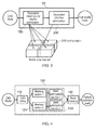
- an embodiment of the proposed system comprises two modules, a decoupled meshing and interior optimization module 100 (meshing means) and a decoupled interface optimization module 200.
- the decoupled meshing and interior optimization module 100 comprises a CAD cutting unit 110, a meshing unit 120, a mesh optimization unit 130, and a mesh merge unit 140.
- the decoupled meshing and interior optimization module 100 is operable to augment a decoupled meshing process, such as that disclosed in EP12173469.3 , with a mesh optimization process.
- the mesh optimization process guarantees that the quality of the elements inside each mesh section will be good. While advanced mesh optimization is in general quite expensive, the fact that it is applied independently and in parallel on each mesh section guarantees the scalability of the process. It should be noted that it is not essential that the mesh optimization process is carried out in parallel on each meshed section, as shown in Figure 4 , although this is advantageous.
- the output of the decoupled meshing and interior optimization module 100 is a partially optimized mesh, where the large majority of elements are of good quality. However, as mentioned above, in general there will be low quality elements at the interfaces between mesh sections.
- the process carried out by the mesh optimization unit 130 guarantees that regions with poor quality elements are isolated, and hence such elements can be easily and naturally decoupled for parallel optimization.
- the decoupled interface optimization module 200 which will be discussed in more detail later, comprises an element extraction unit 210, a set expansion unit 220, a sub-mesh creation unit 230, a sub-mesh optimization unit 240, and a mesh integration unit 250.
- the decoupled interface optimization module 200 is operable to carry out an optimization process on the partially optimized mesh output from the decoupled meshing and interior optimization module 100 to eliminate the remaining low quality elements, again in an efficient and scalable way.
- the optimization process starts with the extraction of a set of low quality elements. This set forms a sub-mesh of the initial (original) mesh.
- the initial mesh is created in such a way that low quality elements can only appear in the regions where mesh sections were glued together, so the number of elements in this set is much smaller than the number of elements in the initial mesh.
- element connectivity information is used to expand this set a given number of times, with the purpose of increasing the amount of data available to the mesh optimization software.
- the expanded set is then decomposed into a number of independent connected components (called sub-meshes of the original mesh) which are optimized, in a parallel decoupled way, using the mesh optimization software. Finally, the optimized sub-meshes are integrated into the initial mesh, which results in a high-quality mesh without any low quality elements.
- the input for the decoupled interface optimization module 200 is a partially optimized mesh.
- This mesh may be generated by the decoupled meshing and interior optimization module 100 using a decoupled parallel meshing system such as shown in Figure 4 , which will now be described in more detail.
- the CAD cutting unit 110 of Figure 4 uses an off-the-shelf CAD Kernel to partition one CAD solid into multiple CAD solids.
- One way of performing the cutting is in a grid-aligned way, where the CAD model is sliced via planes parallel to the coordinate axes.
- the slicing can be performed using Boolean operations present in the CAD Kernel (e.g. CUT operation in the case of the OpenCASCADE CAD Kernel).
- Boolean operations present in the CAD Kernel e.g. CUT operation in the case of the OpenCASCADE CAD Kernel.
- FIG. 6 there are several different ways in which slicing can be done.
- the meshing unit 120 uses an off-the shelf mesher to generate a 3D mesh from each CAD section.
- the meshing process may use the technology described in EP12173469.3 , as illustrated in the flowchart of Figure 7 .
- an off-the-shelf serial mesher is used to create a surface mesh (STEP 1).
- the zones of the meshes found at interfaces between neighboring sections are identified and mesh information is exchanged (STEP 2).
- One way of exchanging information is simply to copy the mesh data from one section (set as source) to the other section (set as destination).
- the interior of the modified surface meshes is meshed in 3D, thus creating a 3D volume mesh for each CAD section (STEP 3).
- the mesh optimization unit 130 (sub-domain mesh optimization means) carries out a mesh optimization process for each mesh section using off-the-shelf serial optimization software, such as STELLAR, in such a way that the mesh on the interfaces between sections is not altered (STEP 4).
- off-the-shelf serial optimization software such as STELLAR
- the mesh merging unit 140 carries out a mesh merging process to combine the mesh sections into one mesh for the entire CAD solid. This can be done efficiently because the mesh sections have been modified so that the meshes on the interfaces are identical. As such, the operation is reduced to removing duplicate nodes and renumbering the resulting mesh (STEP 5).
- a quality metric is computed by element extraction unit 210 for each element in the mesh (STEP 6).
- a mesh quality metric for a tetrahedral element is the sine of the smallest dihedral angle of the tetrahedron (the minimum sine measure). It should be noted that there are many other methods for measuring the quality of elements, such as biased minimum sine measure, volume-length measure, radius ratio, etc..
- a threshold when using the minimum sine quality metric is 10 degrees. The IDs of the selected elements form a set of low quality elements which have been isolated from the partially optimized mesh using the element quality measure.
- the next stage is the decomposition of the set of elements into connected sub-meshes by the sub-mesh creation unit 230.
- these independent connected regions are found using the element connectivity information and identified as respective sets of connected elements (STEP 13).
- sub-meshes are created from each set (STEP 14). If the sub-mesh size exceeds a defined threshold then it may be partitioned into further sub-meshes using a mesh partitioning algorithm.
- each connected sub-mesh is then independently optimized by the sub-mesh optimization unit 240, preferably using the same off-the-shelf serial optimization software as used in STEP 4 (STEP 15).
- STEP 15 the same off-the-shelf serial optimization software as used in STEP 4.
- the only restriction placed on the optimization software is that the mesh on the boundary of each sub-mesh should not be modified, so that it is possible to merge the resulting plurality of optimized sub-meshes into the initial (original) mesh.
- the final stage of the process is for the mesh integration unit 250 to integrate the independently optimized sub-meshes back into the initial mesh (STEPS 16 and 17). Matching of boundary nodes can be done efficiently, as the boundary regions have not been modified.
- a CAD model is partitioned into sections and these sections are then meshed in parallel.
- the output meshes are then all merged back into a single mesh, which is subsequently optimized to remove all bad elements.
- Mesh optimization is done using STELLAR software, which is one of the best mesh optimization programs currently available. However, like most high performance optimization software, STELLAR can only be executed in serial.
- Figure 17 illustrates a case study of this procedure where a CAD model was partitioned into three sections.
- the total meshing time for the model was 29.819s.
- the assumption is made that the CAD model is partitioned in a manner such that the volumes in the partitions are equal.
- the meshing time for the model can be considered to be 9.940s (1/3 * meshing time of complete model).
- the total optimization time was 61.650s and hence the total time for meshing and optimization is 71.590s (9.940s + 61.650s).
- the decoupled meshing process disclosed in EP12173469.3 is combined with an optimization step before the initial mesh merging stage and a further optimization stage is then carried out if low quality elements have been introduced at the "cut interfaces".
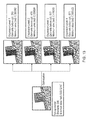
- Figure 18 illustrates the further optimization stage which isolates, optimizes and merges such low quality elements back into the initial (original) mesh.
- This embodiment also makes use of STELLAR for mesh optimization.
- mesh optimization can be executed in parallel, in a decoupled manner, which leads to increased performance.
- the mesh generation time remains the same at 9.940s.
- the optimization time for the low quality elements at the interface will be the maximum across all the low quality element regions being optimized in parallel.
- the low quality element set that was optimized in processor 2 had a greater optimization time of 6.958s as compared to that of processor 1 which was 6.282s. Therefore, we will consider the total time for optimization of the low quality elements at the cut interfaces to be 6.958s.
- the total time for meshing and optimization using an embodiment of the present invention was: 37.448s. Comparing this to the processing time of 71.590s in the comparative example, it can be seen that the proposed system has a 47.691% reduction in the total time for mesh optimization.
- an embodiment of the present invention can generate high quality meshes more rapidly, in a decoupled, parallel way, even if the optimization software employed is not parallel.
- Embodiments of the present invention may be implemented in hardware, or as software modules running on one or more processors, or on a combination thereof. That is, those skilled in the art will appreciate that a microprocessor or digital signal processor (DSP) may be used in practice to implement some or all of the functionality described above.
- DSP digital signal processor
- the invention may also be embodied as one or more device or apparatus programs (e.g. computer programs and computer program products) for carrying out part or all of the methods described herein.
- Such programs embodying the present invention may be stored on computer-readable media, or could, for example, be in the form of one or more signals.
- signals may be data signals downloadable from an Internet website, or provided on a carrier signal, or in any other form.
Landscapes
- Engineering & Computer Science (AREA)
- Physics & Mathematics (AREA)
- Theoretical Computer Science (AREA)
- Geometry (AREA)
- General Physics & Mathematics (AREA)
- Software Systems (AREA)
- Computer Graphics (AREA)
- Computer Hardware Design (AREA)
- Evolutionary Computation (AREA)
- General Engineering & Computer Science (AREA)
- Management, Administration, Business Operations System, And Electronic Commerce (AREA)
- Architecture (AREA)
Abstract
Description
- The present invention relates to mesh quality improvement in Computer Aided Engineering.
- Computed Aided Engineering (CAE), the use of computer software for the purpose of modelling and simulating the behaviour of products in order to improve their quality, has become nearly ubiquitous in the manufacturing industry. Areas covered by CAE include, but are not limited to, stress and thermal analysis, fluid dynamics and kinematics.
- A typical CAE process starts with a Computer Aided Design (CAD) file which represents the geometrical model of the object that is analyzed. The CAD file, created using specialized CAD software, passes first through a pre-processing step where the geometry is partitioned (meshed) into a very large number of elements, which form what is called a mesh. An example of a computational mesh is shown in
Figure 1 of the accompanying drawings. The mesh, accompanied by boundary conditions, is then sent to a solver which uses standard numerical techniques in order to compute the result of the analysis. - Currently available meshers can be divided into two categories: serial and parallel. Serial meshers are restricted to the computational power of only one processor and to the memory attached to it. With a mesh of
order 1 Million elements requiring in the order of 1 GB of memory to create, it is clear that memory is a severe limitation for such codes. Parallel meshers are able to create much larger meshes and in a much shorter time by distributing the workload to a number of processors found either in one computer or, more often, in a number of computers connected by a network. In accordance with the amount of communication performed between the processors while meshing, parallel mesh generators can be further divided into three categories: tightly coupled, loosely coupled and decoupled. In the serial or parallel - coupled case, one or more processors work to create a single mesh. The quality of this mesh will in general be better than for the decoupled case. However, as this type of meshing is not scalable, the meshing time will in general be very long, especially for complex models such as the ones found in industrial CAD models. Only decoupled parallel meshers (which require no communication or synchronization between different processing parts) can achieve 100% reuse of the serial meshing code and are truly scalable. - Scalability is achieved by partitioning the domain that is to be meshed into a number of disjoint sub-domains, which are then independently meshed, so the meshing time is much shorter. Such a scalable parallel-decoupled mesher was recently proposed in
EP12173469.3 - The creation of a high quality mesh is very important as it can both reduce the time spent in the solver and increase the accuracy of the solution. The quality of the mesh can be improved with specialized tools ranging from simple Laplacian smoothing (see Electrical Engineering and Computer Sciences University of California at Berkeley, 2008 "Improving Tetrahedral Meshes" page 21) to complex optimization tools like STELLAR (see " Stellar-A Tetrahedral Mesh Improvement program", http://www.cs.berkelev.edu/-jrs/stellar/#about) that perform complex sequences of operations on mesh nodes and elements. While the use of complex optimization tools usually results in much higher quality meshes as compared with simple ones, it is also much more expensive. Moreover, high quality mesh optimization codes are very time consuming. A high quality mesh optimization tool such as STELLAR can take as much as 10 times longer than mesh generation, which means such codes cannot be used in day-to-day production work. The natural way of overcoming this problem would be to make use of the multicore CPUs available in modern computers and computer clusters. However, this is currently not possible because many such codes (e.g. STELLAR) are serial in nature and parallelizing them is not straightforward.
- Zavattieri, P., Dari, E. and Buscaglia, G. 1996: "Optimization strategies in unstructured mesh generation" International Journal for Numerical Methods in Engineering, 39 (12), pp. 2055-2071, discloses an optimization method for unstructured 3-D finite element meshes. This document discusses different algorithms for improving overall mesh quality including smoothing algorithms, but it does not address scalability.
- Mesh optimization software called "Mesquite Mesh Optimization Toolkit" (Sandia Labs, http://trilinos.sandia.gov/packages/mesquite/) performs smoothing operations in parallel, but is not readily scalable.
- It is desirable to provide a method of generating high quality computational meshes in a decoupled and thus scalable manner.
- According to an embodiment of a first aspect of the present invention there is provided a method for use in meshing a CAD domain in a computer-aided design (CAD) or computer-aided engineering (CAE) system, which method comprises carrying out a procedure comprising: obtaining a set of mesh elements by extracting, from a previously-generated mesh of the CAD domain which has undergone a mesh element optimization process in respect of interior elements of the previously-generated mesh, mesh elements which do not satisfy a preselected mesh quality metric; decomposing the set of mesh elements into connected sub-meshes; carrying out a serial mesh element optimization process in respect of each sub-mesh independently and in parallel, under the condition that boundary nodes of sub-meshes are not moved, to obtain optimized sub-meshes; and obtaining an optimized mesh of the CAD domain by integrating the optimized sub-meshes into the previously-generated mesh.
- A method embodying the present invention is capable of creating a high quality mesh in a faster and more scalable way than existing methods, using serial mesh optimization code yet taking advantage of parallel processing in an efficient way.
- In particular, an embodiment of the present invention can provide an improvement over decoupled meshing methods which can create low quality elements at the interface between domains. Moreover, it can provide a method of performing decoupled parallel mesh optimization using a mesh optimization code which may not be parallel.
- In a method embodying the present invention, obtaining a set of mesh elements may further comprise, after extracting mesh elements which do not satisfy the preselected mesh quality metric, using mesh element connectivity in respect of the extracted mesh elements to identify additional mesh elements for inclusion in the set such that the number of mesh elements in the set is expanded to a required level.
- A method embodying the present invention may further comprise, before carrying out the procedure, generating a mesh for use in the procedure by splitting the CAD domain into a plurality of sub-domains, creating a sub-domain mesh in respect of each sub-domain, optimizing interior elements of each sub-domain mesh, and merging the resulting sub-domain meshes together to form the mesh. The sub-meshes may desirably be created using a parallel decoupled meshing process. The interior elements of each sub-domain mesh are preferably optimized using a serial mesh element optimization process. The mesh optimization process may desirably be carried out on the respective sub-meshes independently and in parallel.
- According to an embodiment of a second aspect of the present invention there is provided apparatus for use in meshing a CAD domain in a computer-aided design (CAD) or computer-aided engineering (CAE) system, which apparatus comprises: set extraction means configured to obtain a set of mesh elements by extracting, from a previously-generated mesh of the CAD domain which has undergone a mesh element optimization process in respect of interior elements of the previously-generated mesh, mesh elements which do not satisfy a preselected mesh quality metric; sub-mesh creation means configured to decompose the set of mesh elements into connected sub-meshes; sub-mesh optimization means configured to carry out a serial mesh element optimization process in respect of each sub-mesh independently and in parallel, under the condition that boundary nodes of sub-meshes are not moved, to obtain optimized sub-meshes; and mesh integration means configured to obtain an optimized mesh of the CAD domain by integrating the optimized sub-meshes into the previously-generated mesh.
- Apparatus embodying the present invention facilitates the creation of a high quality mesh in a faster and more scalable way than existing apparatus, using serial mesh optimization code yet taking advantage of parallel processing in an efficient way. It can provide an improvement over decoupled meshing apparatus which can create low quality elements at the interface between domains. Moreover, it can perform decoupled parallel mesh optimization using a mesh optimization code which may not be parallel.
- In apparatus embodying the present invention, the set extraction means may comprise: element extraction means operable to extract mesh elements from the previously-generated mesh which do not satisfy the preselected mesh quality metric; and set expansion means operable to expand the number of mesh elements in the set to a required level by using mesh element connectivity in respect of the extracted mesh elements to identify additional mesh elements for inclusion in the set.
- Apparatus embodying the present invention may further comprising meshing means configured to generate a mesh for supply to the set extraction means, the meshing means comprising: cutting means configured to split the CAD domain into a plurality of sub-domains; sub-domain meshing means configured to create a sub-domain mesh in respect of each sub-domain; sub-domain mesh optimization means configured to optimize interior elements of each sub-domain mesh; and mesh merging means configured to merge the resulting sub-domain meshes together to form the mesh. The sub-domain meshing means are preferably operable to create the sub-meshes using a parallel decoupled meshing process. Desirably, the sub-domain optimization means may be operable to optimize the interior elements of each sub-domain mesh using a serial mesh element optimization process. Preferably the sub-domain optimization means are operable to carry out the mesh optimization process on the respective sub-meshes independently and in parallel.
- According to an embodiment of a third aspect of the present invention there is provided a computer program which, when run on a computer or network of computers, causes that computer or network to carry out a method embodying the first aspect of the present invention or to become apparatus embodying the second aspect of the present invention.
- Reference will now be made, by way of example, to the accompanying drawings, in which:
-
Figure 1 (described above) shows an example of a 3D computational mesh; -
Figure 2 shows an example of a CAD system in which a meshing apparatus embodying the present invention can be used; -
Figure 3 shows a meshing apparatus embodying the present invention; -
Figure 4 shows a decoupled meshing and interior optimization module for use in an embodiment of the present invention; -
Figure 5 shows a decoupled interface optimization module for use in an embodiment of the present invention; -
Figure 6 illustrates a CAD cutting module for use in the present invention; -
Figure 7 is a flowchart illustrating a CAD meshing process for use in the present invention; -
Figure 8 is a flowchart illustrating a parallel decoupled mesh optimization process for use in the present invention; -
Figure 9 is a flowchart illustrating a mesh merging process for use in the present invention; -
Figure 10 is a flowchart illustrating a a low quality element extraction process for use in the present invention; -
Figure 11 is a flowchart illustrating a process for obtaining an expanded element set; -
Figure 12 illustrates an example of element set expansion for facilitating optimization of low quality elements; -
Figure 13 illustrates variation in mesh quality post optimization between different expansion levels; -
Figure 14 is a flowchart illustrating a process for decomposing the expanded element set into connected sub-meshes; -
Figure 15 is a flowchart illustrating a process for performing decoupled parallel optimization of the sub-meshes; -
Figure 16 is a flowchart illustrating a process for integrating optimized sub-meshes in the initial mesh; -
Figure 17 illustrates mesh optimization using a previously-proposed decoupled parallel meshing system; and -
Figure 18 illustrates mesh optimization using a meshing system embodying the present invention. -
Figure 2 shows where a meshing method or meshing apparatus embodying the present invention can be utilized in a CAD system comprising an off-the-shelf CAD engine, an off-the-shelf mesher and an off-the shelf mesh optimizer. - Given a CAD model stored in a data format supported by the CAD engine, an embodiment of the present invention employs the following existing components:
- A meshing code that, given a CAD model, is capable of creating an initial (original) 3D computational mesh
- A CAD engine (also called a CAD kernel) that can read and can perform modifications to the CAD file
- A mesh optimizer that, after reading the mesh file and applying optimization methods known in the art, outputs a mesh with better quality than the initial 3D (original) computational mesh.
- Although not essential in order to provide an improvement over the prior art, it is desirable to generate the initial mesh using a decoupled parallel meshing system, for example such as that proposed in
EP12173469.3 EP12173469.3 - An assembly model is a CAD model consisting of multiple solids, which may or may not be in physical contact with each other. Throughout the present application, the term part will have the meaning of a single solid component of an assembly model. For the sake of consistency, if the input CAD file consists of a single solid, we will refer to it as an assembly with one part. A solid may be split/partitioned into a number of sections. A 2D meshing operation is the discretization of the faces of a solid by 2D elements such as triangles or quadrilaterials. A 3D meshing operation is the discretization of the entire volume of a solid by 3D elements such as tetrahedrals or hexahedrals. A mesh merge operation is the combining of the 3D meshes of the individual sections of a part into one coherent 3D mesh for that part. A coherent mesh is defined as one single connected mesh, without duplicate nodes on the interfaces between sections. A mesh assembly operation is the putting together of the meshes for one or more individual parts into one single mesh for the assembly model. The difference between mesh assembly and mesh merging is that an assembled mesh does not become one single connected mesh. In other words, even if the meshes of two parts are in physical contact, the interface will contain two sets of nodes and elements, one set for each mesh. More formally, there is no element in the assembled mesh which has nodes belonging to the meshes of more than one part.
- As shown in
Figure 3 , an embodiment of the proposed system comprises two modules, a decoupled meshing and interior optimization module 100 (meshing means) and a decoupledinterface optimization module 200. - As shown in
Figure 4 , the decoupled meshing andinterior optimization module 100, which will be discussed in more detail later, comprises aCAD cutting unit 110, ameshing unit 120, amesh optimization unit 130, and amesh merge unit 140. The decoupled meshing andinterior optimization module 100 is operable to augment a decoupled meshing process, such as that disclosed inEP12173469.3 Figure 4 , although this is advantageous. - The output of the decoupled meshing and
interior optimization module 100 is a partially optimized mesh, where the large majority of elements are of good quality. However, as mentioned above, in general there will be low quality elements at the interfaces between mesh sections. - The process carried out by the
mesh optimization unit 130 guarantees that regions with poor quality elements are isolated, and hence such elements can be easily and naturally decoupled for parallel optimization. - As shown in
Figure 5 , the decoupledinterface optimization module 200, which will be discussed in more detail later, comprises anelement extraction unit 210, aset expansion unit 220, asub-mesh creation unit 230, asub-mesh optimization unit 240, and amesh integration unit 250. The decoupledinterface optimization module 200 is operable to carry out an optimization process on the partially optimized mesh output from the decoupled meshing andinterior optimization module 100 to eliminate the remaining low quality elements, again in an efficient and scalable way. The optimization process starts with the extraction of a set of low quality elements. This set forms a sub-mesh of the initial (original) mesh. The initial mesh is created in such a way that low quality elements can only appear in the regions where mesh sections were glued together, so the number of elements in this set is much smaller than the number of elements in the initial mesh. Following this, element connectivity information is used to expand this set a given number of times, with the purpose of increasing the amount of data available to the mesh optimization software. The expanded set is then decomposed into a number of independent connected components (called sub-meshes of the original mesh) which are optimized, in a parallel decoupled way, using the mesh optimization software. Finally, the optimized sub-meshes are integrated into the initial mesh, which results in a high-quality mesh without any low quality elements. - As depicted in
Figure 5 , the input for the decoupledinterface optimization module 200 is a partially optimized mesh. This mesh may be generated by the decoupled meshing andinterior optimization module 100 using a decoupled parallel meshing system such as shown inFigure 4 , which will now be described in more detail. - The
CAD cutting unit 110 ofFigure 4 uses an off-the-shelf CAD Kernel to partition one CAD solid into multiple CAD solids. One way of performing the cutting is in a grid-aligned way, where the CAD model is sliced via planes parallel to the coordinate axes. The slicing can be performed using Boolean operations present in the CAD Kernel (e.g. CUT operation in the case of the OpenCASCADE CAD Kernel). However, there are several different ways in which slicing can be done. One example is illustrated inFigure 6 . - The meshing unit 120 (sub-domain meshing means) uses an off-the shelf mesher to generate a 3D mesh from each CAD section. The meshing process may use the technology described in
EP12173469.3 Figure 7 . In this case, for each CAD section in parallel, an off-the-shelf serial mesher is used to create a surface mesh (STEP 1). Following this, the zones of the meshes found at interfaces between neighboring sections are identified and mesh information is exchanged (STEP 2). One way of exchanging information is simply to copy the mesh data from one section (set as source) to the other section (set as destination). After the surface meshes have been modified, the interior of the modified surface meshes is meshed in 3D, thus creating a 3D volume mesh for each CAD section (STEP 3). - As shown in the flowchart of
Figure 8 , the mesh optimization unit 130 (sub-domain mesh optimization means) carries out a mesh optimization process for each mesh section using off-the-shelf serial optimization software, such as STELLAR, in such a way that the mesh on the interfaces between sections is not altered (STEP 4). - As shown in the flowchart of
Figure 9 . themesh merging unit 140 carries out a mesh merging process to combine the mesh sections into one mesh for the entire CAD solid. This can be done efficiently because the mesh sections have been modified so that the meshes on the interfaces are identical. As such, the operation is reduced to removing duplicate nodes and renumbering the resulting mesh (STEP 5). - Although all mesh sections have been fully optimized, the combined mesh is only partially optimized since it is possible that low quality elements have been created at the interfaces between neighboring sections. This partially optimized mesh is processed by the decoupled
interface optimization module 200, as will now be described. - As illustrated in the flowchart of
Figure 10 , starting with the partially optimized mesh ofFigure 9 as input, a quality metric is computed byelement extraction unit 210 for each element in the mesh (STEP 6). One example of a mesh quality metric for a tetrahedral element is the sine of the smallest dihedral angle of the tetrahedron (the minimum sine measure). It should be noted that there are many other methods for measuring the quality of elements, such as biased minimum sine measure, volume-length measure, radius ratio, etc.. After the metric has been computed for each element, only the elements whose quality falls below a set threshold are selected for extraction (STEP 7). One example of a threshold when using the minimum sine quality metric is 10 degrees. The IDs of the selected elements form a set of low quality elements which have been isolated from the partially optimized mesh using the element quality measure. - In order to be able to efficiently insert the optimized region back into the solid mesh it is necessary to leave the boundaries untouched. However, optimizing a relatively small number of elements (as is the case for the set of low quality elements) with such a constraint can lead to a sub-optimal result, as the mesh optimization software does not have enough freedom to operate. For this reason, the sub-mesh that is to be sent to the
sub-mesh optimization unit 240 is expanded by the setexpansion unit 220 to include neighboring elements, and the condition for not modifying the boundaries is applied to this larger set. The flowchart ofFigure 11 illustrates the operation of the setexpansion unit 220 and an example of the set expansion process is shown inFigure 12 . Firstly, element connectivity information is extracted from the partially optimized mesh (STEP 8). Then a check is made to determine whether the set expansion process has been carried out N times (STEP 9). If "Yes", then the expanded element set is complete. Otherwise, for all elements presently in the expanded element set (STEP 10), a list of neighbouring elements, according to the connectivity information, is obtained (STEP 11) and any neighbouring elements not already in the expanded element set are added to that set (STEP 12). This process is repeated N times (typically N=2 or 3) in order to improve the quality of the optimization, as illustrated inFigure 13 . - The next stage is the decomposition of the set of elements into connected sub-meshes by the
sub-mesh creation unit 230. As low quality elements can now only exist at the interfaces between neighboring sections, there is a high probability that these will be grouped into several independent sub-regions. As illustrated in the flowchart ofFigure 14 , these independent connected regions are found using the element connectivity information and identified as respective sets of connected elements (STEP 13). After these sets are identified, sub-meshes are created from each set (STEP 14). If the sub-mesh size exceeds a defined threshold then it may be partitioned into further sub-meshes using a mesh partitioning algorithm. - As illustrated in the flowchart of
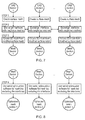
Figure 15 , similarly to the operation of themesh optimization unit 130, each connected sub-mesh is then independently optimized by thesub-mesh optimization unit 240, preferably using the same off-the-shelf serial optimization software as used in STEP 4 (STEP 15). Overall this becomes a decoupled parallel optimization, even though a serial mesh optimization software is used. The only restriction placed on the optimization software is that the mesh on the boundary of each sub-mesh should not be modified, so that it is possible to merge the resulting plurality of optimized sub-meshes into the initial (original) mesh. - The final stage of the process, illustrated in
Figure 16 , is for themesh integration unit 250 to integrate the independently optimized sub-meshes back into the initial mesh (STEPS 16 and 17). Matching of boundary nodes can be done efficiently, as the boundary regions have not been modified. - An advantage of an embodiment of the present invention over the prior art will now be explained with reference to a comparative example. Both the embodiment described and the comparative example employ the decoupled parallel meshing system disclosed in
EP12173469.3 - In the comparative example, a CAD model is partitioned into sections and these sections are then meshed in parallel. The output meshes are then all merged back into a single mesh, which is subsequently optimized to remove all bad elements. Mesh optimization is done using STELLAR software, which is one of the best mesh optimization programs currently available. However, like most high performance optimization software, STELLAR can only be executed in serial.
-
Figure 17 illustrates a case study of this procedure where a CAD model was partitioned into three sections. The total meshing time for the model was 29.819s. For illustration, the assumption is made that the CAD model is partitioned in a manner such that the volumes in the partitions are equal. With this assumption the meshing time for the model can be considered to be 9.940s (1/3 * meshing time of complete model). The total optimization time was 61.650s and hence the total time for meshing and optimization is 71.590s (9.940s + 61.650s). - In contrast, in an embodiment of the present invention, the decoupled meshing process disclosed in
EP12173469.3 Figure 18 illustrates the further optimization stage which isolates, optimizes and merges such low quality elements back into the initial (original) mesh. This embodiment also makes use of STELLAR for mesh optimization. However, using a method embodying the present invention, mesh optimization can be executed in parallel, in a decoupled manner, which leads to increased performance. - In this embodiment of the present invention the meshing and optimization times were as follows:
- Mesh generation: 9.940s
- Decoupled mesh optimization: 20.550s (1/3 * 61.650s)
- Mesh optimization of low quality elements at interface: 6.958s (maximum time for optimization across all sections optimized in parallel)
- The mesh generation time remains the same at 9.940s. For the decoupled mesh optimization, since this is performed before the mesh merging it can be assumed to take a third of the time as it did to optimize the complete mesh (as the mesh is split into three parts and optimized in parallel). Further, the optimization time for the low quality elements at the interface will be the maximum across all the low quality element regions being optimized in parallel. As depicted in
Figure 18 , the low quality element set that was optimized inprocessor 2 had a greater optimization time of 6.958s as compared to that ofprocessor 1 which was 6.282s. Therefore, we will consider the total time for optimization of the low quality elements at the cut interfaces to be 6.958s. - The total time for meshing and optimization using an embodiment of the present invention was: 37.448s. Comparing this to the processing time of 71.590s in the comparative example, it can be seen that the proposed system has a 47.691% reduction in the total time for mesh optimization.
- Thus, an embodiment of the present invention can generate high quality meshes more rapidly, in a decoupled, parallel way, even if the optimization software employed is not parallel.
- Embodiments of the present invention may be implemented in hardware, or as software modules running on one or more processors, or on a combination thereof. That is, those skilled in the art will appreciate that a microprocessor or digital signal processor (DSP) may be used in practice to implement some or all of the functionality described above.
- The invention may also be embodied as one or more device or apparatus programs (e.g. computer programs and computer program products) for carrying out part or all of the methods described herein. Such programs embodying the present invention may be stored on computer-readable media, or could, for example, be in the form of one or more signals. Such signals may be data signals downloadable from an Internet website, or provided on a carrier signal, or in any other form.
Claims (13)
- A method for use in meshing a CAD domain in a computer-aided design (CAD) or computer-aided engineering (CAE) system, which method comprises carrying out a procedure comprising:obtaining a set of mesh elements by extracting, from a previously-generated mesh of the CAD domain which has undergone a mesh element optimization process in respect of interior elements of the previously-generated mesh, mesh elements which do not satisfy a preselected mesh quality metric;decomposing the set of mesh elements into connected sub-meshes;carrying out a serial mesh element optimization process in respect of each sub-mesh independently and in parallel, under the condition that boundary nodes of sub-meshes are not moved, to obtain optimized sub-meshes; andobtaining an optimized mesh of the CAD domain by integrating the optimized sub-meshes into the previously-generated mesh.
- A method as claimed in claim 1, wherein obtaining a set of mesh elements further comprises, after extracting mesh elements which do not satisfy the preselected mesh quality metric, using mesh element connectivity in respect of the extracted mesh elements to identify additional mesh elements for inclusion in the set such that the number of mesh elements in the set is expanded to a required level.
- A method as claimed in claim 1 or 2, further comprising, before carrying out the procedure, generating a mesh for use in the procedure by splitting the CAD domain into a plurality of sub-domains, creating a sub-domain mesh in respect of each sub-domain, optimizing interior elements of each sub-domain mesh, and merging the resulting sub-domain meshes together to form the mesh.
- A method as claimed in claim 3, wherein the sub-meshes are created using a parallel decoupled meshing process.
- A method as claimed in claim 3 or 4, wherein the interior elements of each sub-domain mesh are optimized using a serial mesh element optimization process.
- A method as claimed in claim 5, wherein the mesh optimization process of claim 5 is carried out on the respective sub-meshes independently and in parallel.
- Apparatus (10) for use in meshing a CAD domain in a computer-aided design (CAD) or computer-aided engineering (CAE) system, which apparatus comprises:set extraction means (210, 220) configured to obtain a set of mesh elements by extracting, from a previously-generated mesh of the CAD domain which has undergone a mesh element optimization process in respect of interior elements of the previously-generated mesh, mesh elements which do not satisfy a preselected mesh quality metric;sub-mesh creation means (230) configured to decompose the set of mesh elements into connected sub-meshes;sub-mesh optimization means (240) configured to carry out a serial mesh element optimization process in respect of each sub-mesh independently and in parallel, under the condition that boundary nodes of sub-meshes are not moved, to obtain optimized sub-meshes; andmesh integration means (250) configured to obtain an optimized mesh of the CAD domain by integrating the optimized sub-meshes into the previously-generated mesh.
- Apparatus as claimed in claim 7, wherein the set extraction means (210, 220) comprise:element extraction means (210) operable to extract mesh elements from the previously-generated mesh which do not satisfy the preselected mesh quality metric; andset expansion means (220) operable to expand the number of mesh elements in the set to a required level by using mesh element connectivity in respect of the extracted mesh elements to identify additional mesh elements for inclusion in the set.
- Apparatus as claimed in claim 7 or 8, further comprising meshing means (100) configured to generate a mesh for supply to the set extraction means (210, 220), the meshing means comprising:cutting means (110) configured to split the CAD domain into a plurality of sub-domains;sub-domain meshing means (120) configured to create a sub-domain mesh in respect of each sub-domain;sub-domain mesh optimization means (130) configured to optimize interior elements of each sub-domain mesh; andmesh merging means (140) configured to merge the resulting sub-domain meshes together to form the mesh.
- Apparatus as claimed in claim 9, wherein the sub-domain meshing means (120) are operable to create the sub-meshes using a parallel decoupled meshing process.
- Apparatus as claimed in claim 9 or 10, wherein the sub-domain optimization means (130) are operable to optimize the interior elements of each sub-domain mesh using a serial mesh element optimization process.
- Apparatus as claimed in claim 11, wherein the sub-domain optimization means (130) are operable to carry out the mesh optimization process on the respective sub-meshes independently and in parallel.
- A computer program which, when run on a computer or network of computers, causes that computer or network to carry out the method of any one of claims 1 to 6 or to become apparatus as claimed in any one of claims 7 to 12.
Priority Applications (3)
| Application Number | Priority Date | Filing Date | Title |
|---|---|---|---|
| EP14153939.5A EP2905744A1 (en) | 2014-02-05 | 2014-02-05 | Mesh quality improvement in computer aided engineering |
| JP2014109870A JP2015149052A (en) | 2014-02-05 | 2014-05-28 | Mesh quality improvement in computer aided engineering |
| US14/291,149 US9418476B2 (en) | 2014-02-05 | 2014-05-30 | Mesh quality improvement in computer aided engineering |
Applications Claiming Priority (1)
| Application Number | Priority Date | Filing Date | Title |
|---|---|---|---|
| EP14153939.5A EP2905744A1 (en) | 2014-02-05 | 2014-02-05 | Mesh quality improvement in computer aided engineering |
Publications (1)
| Publication Number | Publication Date |
|---|---|
| EP2905744A1 true EP2905744A1 (en) | 2015-08-12 |
Family
ID=50112707
Family Applications (1)
| Application Number | Title | Priority Date | Filing Date |
|---|---|---|---|
| EP14153939.5A Withdrawn EP2905744A1 (en) | 2014-02-05 | 2014-02-05 | Mesh quality improvement in computer aided engineering |
Country Status (3)
| Country | Link |
|---|---|
| US (1) | US9418476B2 (en) |
| EP (1) | EP2905744A1 (en) |
| JP (1) | JP2015149052A (en) |
Cited By (1)
| Publication number | Priority date | Publication date | Assignee | Title |
|---|---|---|---|---|
| US11126766B2 (en) | 2016-10-31 | 2021-09-21 | Siemens Industry Software Inc. | System and method for element quality improvement in 3D quadrilateral-dominant surface meshes |
Families Citing this family (7)
| Publication number | Priority date | Publication date | Assignee | Title |
|---|---|---|---|---|
| JP2017004305A (en) * | 2015-06-11 | 2017-01-05 | 株式会社日立製作所 | Analytic model creation support system, analytic model creation support device, and analytic model creation support program |
| US11042146B2 (en) | 2017-11-17 | 2021-06-22 | Kodak Alaris Inc. | Automated 360-degree dense point object inspection |
| US11049236B2 (en) * | 2017-11-17 | 2021-06-29 | Kodak Alaris Inc. | Automated in-line object inspection |
| WO2019229965A1 (en) * | 2018-06-01 | 2019-12-05 | 株式会社プルートス | Mesh generation system, mesh generation program, and mesh generation method |
| CN110866313B (en) * | 2019-10-22 | 2023-05-16 | 温州大学 | A method for digital twin modeling of circuit breaker automatic detection pipeline |
| CN111325821B (en) * | 2020-02-18 | 2023-06-06 | Oppo广东移动通信有限公司 | Grid model processing method and device, equipment and storage medium |
| CN112613216A (en) * | 2020-12-24 | 2021-04-06 | 中国电建集团贵阳勘测设计研究院有限公司 | Rapid high-quality finite element modeling method for complex structure |
Citations (3)
| Publication number | Priority date | Publication date | Assignee | Title |
|---|---|---|---|---|
| US20040117163A1 (en) * | 1997-10-08 | 2004-06-17 | Rivara Maria Cecilia | Longest-Edge Refinement and Derefinement System and Method for Automatic Mesh Generation |
| US20070011646A1 (en) * | 2005-06-24 | 2007-01-11 | College Of William And Mary | Parallel Decoupled Mesh Generation |
| EP2680231A1 (en) * | 2012-06-25 | 2014-01-01 | Fujitsu Limited | Decoupled parallel meshing in computer aided design |
-
2014
- 2014-02-05 EP EP14153939.5A patent/EP2905744A1/en not_active Withdrawn
- 2014-05-28 JP JP2014109870A patent/JP2015149052A/en not_active Withdrawn
- 2014-05-30 US US14/291,149 patent/US9418476B2/en not_active Expired - Fee Related
Patent Citations (3)
| Publication number | Priority date | Publication date | Assignee | Title |
|---|---|---|---|---|
| US20040117163A1 (en) * | 1997-10-08 | 2004-06-17 | Rivara Maria Cecilia | Longest-Edge Refinement and Derefinement System and Method for Automatic Mesh Generation |
| US20070011646A1 (en) * | 2005-06-24 | 2007-01-11 | College Of William And Mary | Parallel Decoupled Mesh Generation |
| EP2680231A1 (en) * | 2012-06-25 | 2014-01-01 | Fujitsu Limited | Decoupled parallel meshing in computer aided design |
Non-Patent Citations (5)
| Title |
|---|
| COUPEZ: "Parallel meshing and remeshing", APPLIED MATHEMATICAL MODELLING, vol. 25, no. 2, 2000, pages 153, XP055133959, ISSN: 0307-904X, DOI: 10.1016/S0307-904X(00)00045-7 * |
| IMPROVING TETRAHEDRAL MESHES, pages 21 |
| STELLAR - A TETRAHEDRAL MESH IMPROVEMENT PROGRAM, Retrieved from the Internet <URL:http://www.cs,berkelev.edu/~jrs/stellar/#about> |
| U. TREMEL ET AL: "Parallel remeshing of unstructured volume grids for CFD applications", INTERNATIONAL JOURNAL FOR NUMERICAL METHODS IN FLUIDS, vol. 53, no. 8, 20 March 2007 (2007-03-20), pages 1361 - 1379, XP055136200, ISSN: 0271-2091, DOI: 10.1002/fld.1195 * |
| ZAVATTIERI, P.; DARI, E.; BUSCAGLIA, G.: "Optimization strategies in unstructured mesh generation", INTERNATIONAL JOURNAL FOR NUMERICAL METHODS IN ENGINEERING, vol. 39, no. 12, 1996, pages 2055 - 2071 |
Cited By (1)
| Publication number | Priority date | Publication date | Assignee | Title |
|---|---|---|---|---|
| US11126766B2 (en) | 2016-10-31 | 2021-09-21 | Siemens Industry Software Inc. | System and method for element quality improvement in 3D quadrilateral-dominant surface meshes |
Also Published As
| Publication number | Publication date |
|---|---|
| US9418476B2 (en) | 2016-08-16 |
| JP2015149052A (en) | 2015-08-20 |
| US20150221130A1 (en) | 2015-08-06 |
Similar Documents
| Publication | Publication Date | Title |
|---|---|---|
| US9418476B2 (en) | Mesh quality improvement in computer aided engineering | |
| Nicolae et al. | Deepfreeze: Towards scalable asynchronous checkpointing of deep learning models | |
| US8259104B2 (en) | Domain decomposition by the advancing-partition method for parallel unstructured grid generation | |
| US10496704B2 (en) | Quantifying consistency of a system architecture by comparing analyses of property graph data models representing different versions of the system architecture | |
| Bassi et al. | Agglomeration based discontinuous Galerkin discretization of the Euler and Navier–Stokes equations | |
| KR101666937B1 (en) | Apparatus for processing large data of 3 dimentional point cloud and method thereof | |
| Löhner | Recent advances in parallel advancing front grid generation | |
| Hao et al. | An efficient curvature‐based partitioning of large‐scale STL models | |
| US9177418B1 (en) | System and method for converting computer aided design data into a three dimensional model | |
| EP2819097A1 (en) | Decoupled parallel meshing in computer aided design | |
| WO2016173260A1 (en) | Method and apparatus for decomposing three-dimensional model based on generalized cylinders | |
| EP3596672A1 (en) | Quantifying robustness by analyzing a property graph data model | |
| Kim et al. | Enhanced volume decomposition minimizing overlapping volumes for the recognition of design features | |
| Wang et al. | Tac+: Optimizing error-bounded lossy compression for 3d amr simulations | |
| JP2014225257A (en) | Method and system for dividing undirected graph expressing matrix to be used for cae by using bidirectional level set | |
| US10042962B2 (en) | Mid-surface extraction for finite element analysis | |
| Lee et al. | Surface mesh generation for dirty geometries by the Cartesian shrink-wrapping technique | |
| JP6998045B2 (en) | Machining support method, machining support system, and machining support program | |
| JP6253429B2 (en) | Method and system for generating contact surface definitions with lower and second order finite elements in numerical simulation of impact events | |
| JP2017004305A (en) | Analytic model creation support system, analytic model creation support device, and analytic model creation support program | |
| CN103890671B (en) | Parallel decentralized approach and parallel dispersion process device | |
| Soner et al. | Generating multibillion element unstructured meshes on distributed memory parallel machines | |
| Mounir et al. | FEM simulation based on CAD model simplification: a comparison study between the hybrid method and the technique using a removing details | |
| Böhm et al. | On the development of strategies for an efficient semi-automated hex-meshing process of complex jet engine component assemblies | |
| Garimella et al. | Solution of the diffusion equation in multi‐material domains by sub‐division of elements along reconstructed interfaces |
Legal Events
| Date | Code | Title | Description |
|---|---|---|---|
| PUAI | Public reference made under article 153(3) epc to a published international application that has entered the european phase |
Free format text: ORIGINAL CODE: 0009012 |
|
| 17P | Request for examination filed |
Effective date: 20150119 |
|
| AK | Designated contracting states |
Kind code of ref document: A1 Designated state(s): AL AT BE BG CH CY CZ DE DK EE ES FI FR GB GR HR HU IE IS IT LI LT LU LV MC MK MT NL NO PL PT RO RS SE SI SK SM TR |
|
| AX | Request for extension of the european patent |
Extension state: BA ME |
|
| GRAP | Despatch of communication of intention to grant a patent |
Free format text: ORIGINAL CODE: EPIDOSNIGR1 |
|
| INTG | Intention to grant announced |
Effective date: 20170719 |
|
| STAA | Information on the status of an ep patent application or granted ep patent |
Free format text: STATUS: THE APPLICATION IS DEEMED TO BE WITHDRAWN |
|
| 18D | Application deemed to be withdrawn |
Effective date: 20171130 |