EP2905534B1 - Automatic water-adding vaporization pot - Google Patents
Automatic water-adding vaporization pot Download PDFInfo
- Publication number
- EP2905534B1 EP2905534B1 EP13833430.5A EP13833430A EP2905534B1 EP 2905534 B1 EP2905534 B1 EP 2905534B1 EP 13833430 A EP13833430 A EP 13833430A EP 2905534 B1 EP2905534 B1 EP 2905534B1
- Authority
- EP
- European Patent Office
- Prior art keywords
- acquisition board
- temperature acquisition
- temperature
- pot body
- automatic water
- Prior art date
- Legal status (The legal status is an assumption and is not a legal conclusion. Google has not performed a legal analysis and makes no representation as to the accuracy of the status listed.)
- Not-in-force
Links
Images




Classifications
-
- F—MECHANICAL ENGINEERING; LIGHTING; HEATING; WEAPONS; BLASTING
- F22—STEAM GENERATION
- F22B—METHODS OF STEAM GENERATION; STEAM BOILERS
- F22B1/00—Methods of steam generation characterised by form of heating method
- F22B1/28—Methods of steam generation characterised by form of heating method in boilers heated electrically
- F22B1/284—Methods of steam generation characterised by form of heating method in boilers heated electrically with water in reservoirs
- F22B1/285—Methods of steam generation characterised by form of heating method in boilers heated electrically with water in reservoirs the water being fed by a pump to the reservoirs
-
- F—MECHANICAL ENGINEERING; LIGHTING; HEATING; WEAPONS; BLASTING
- F22—STEAM GENERATION
- F22D—PREHEATING, OR ACCUMULATING PREHEATED, FEED-WATER FOR STEAM GENERATION; FEED-WATER SUPPLY FOR STEAM GENERATION; CONTROLLING WATER LEVEL FOR STEAM GENERATION; AUXILIARY DEVICES FOR PROMOTING WATER CIRCULATION WITHIN STEAM BOILERS
- F22D5/00—Controlling water feed or water level; Automatic water feeding or water-level regulators
- F22D5/26—Automatic feed-control systems
- F22D5/30—Automatic feed-control systems responsive to both water level and amount of steam withdrawn or steam pressure
-
- F—MECHANICAL ENGINEERING; LIGHTING; HEATING; WEAPONS; BLASTING
- F22—STEAM GENERATION
- F22D—PREHEATING, OR ACCUMULATING PREHEATED, FEED-WATER FOR STEAM GENERATION; FEED-WATER SUPPLY FOR STEAM GENERATION; CONTROLLING WATER LEVEL FOR STEAM GENERATION; AUXILIARY DEVICES FOR PROMOTING WATER CIRCULATION WITHIN STEAM BOILERS
- F22D5/00—Controlling water feed or water level; Automatic water feeding or water-level regulators
- F22D5/26—Automatic feed-control systems
-
- F—MECHANICAL ENGINEERING; LIGHTING; HEATING; WEAPONS; BLASTING
- F22—STEAM GENERATION
- F22B—METHODS OF STEAM GENERATION; STEAM BOILERS
- F22B35/00—Control systems for steam boilers
- F22B35/18—Applications of computers to steam-boiler control
-
- F—MECHANICAL ENGINEERING; LIGHTING; HEATING; WEAPONS; BLASTING
- F22—STEAM GENERATION
- F22B—METHODS OF STEAM GENERATION; STEAM BOILERS
- F22B37/00—Component parts or details of steam boilers
- F22B37/02—Component parts or details of steam boilers applicable to more than one kind or type of steam boiler
- F22B37/42—Applications, arrangements or dispositions of alarm or automatic safety devices
- F22B37/46—Applications, arrangements or dispositions of alarm or automatic safety devices responsive to low or high water level, e.g. for checking, suppressing or extinguishing combustion in boilers
-
- F—MECHANICAL ENGINEERING; LIGHTING; HEATING; WEAPONS; BLASTING
- F22—STEAM GENERATION
- F22D—PREHEATING, OR ACCUMULATING PREHEATED, FEED-WATER FOR STEAM GENERATION; FEED-WATER SUPPLY FOR STEAM GENERATION; CONTROLLING WATER LEVEL FOR STEAM GENERATION; AUXILIARY DEVICES FOR PROMOTING WATER CIRCULATION WITHIN STEAM BOILERS
- F22D5/00—Controlling water feed or water level; Automatic water feeding or water-level regulators
- F22D5/26—Automatic feed-control systems
- F22D5/32—Automatic feed-control systems influencing the speed or delivery pressure of the feed pumps
-
- F—MECHANICAL ENGINEERING; LIGHTING; HEATING; WEAPONS; BLASTING
- F22—STEAM GENERATION
- F22G—SUPERHEATING OF STEAM
- F22G5/00—Controlling superheat temperature
Definitions
- the present disclosure relates to a vaporization pot, and more particularly to an automatic water-adding vaporization pot.
- the French Patent FR2755706A1 published on May 15, 1998 discloses an automatic water-adding steam iron, in which the internal temperature of the pot body is detected by the temperature controller disposed at the outer surface of the pot body, then by continuously sampling values, the water level in the pot body is obtained based on an algorithm, so that the water is added to the pot body under the control of the water pump.
- This control method needs a complicated control circuit for calculating, and the control is not exact because of the influences of the mounting location of the temperature controller outside of the pot body and the environment. Moreover, this control method is high in cost.
- Chinese Patent Application CN-101799153-A discloses another automatic water-adding vaporization pot in the related art.
- an automatic water-adding vaporization pot comprising a pot body, a heating component mounted on the pot body, a water pump connected with the pot body, and a control circuit for controlling the water pump.
- the automatic water-adding vaporization pot further comprises: a first temperature acquisition board and a water-shortage and temperature sensing element mounted on the first temperature acquisition board, one end of the first temperature acquisition board is connected with the heating component or to a position of the pot body in proximity to the heating component, remaining parts of the first temperature acquisition board are away from the pot body, the water-shortage and temperature sensing element is mounted at a position of the first temperature acquisition board away from the pot body, and the water-shortage and temperature sensing element is connected with the control circuit.
- a running time of the water pump is depended on a heat transfer rate and a heat capacity of the first temperature acquisition board.
- the heat transfer rate and the heat capacity of the first temperature acquisition board are depended on a mounting position, a volume and a shape of the first temperature acquisition board.
- the first temperature acquisition board and the heating component are formed integrally.
- the heating component is provided with a heating tube, and the one end of the first temperature acquisition board is located at the heating tube.
- the one end of the first temperature acquisition board is bent and then connected with the heating component, and an interval between the remaining part of the first temperature acquisition board and the pot body ranges from 0.5mm to 20mm.
- the first temperature acquisition board and the heating component are connected together by welding or bolt connection.
- a mounting hole is formed in the part of the first temperature acquisition board away from the pot body, a support member is mounted in the mounting hole, and a bottom of the support member is supported on the pot body.
- a second temperature acquisition board is further provided, and a temperature sensor for controlling a steam pressure is mounted on the second temperature acquisition board.
- the first temperature acquisition board is further provided with a temperature sensor for controlling a steam pressure.
- an on-off switch is connected into a power supply circuit of the heating component, and the on-off switch and the water-shortage and temperature sensing element are linked, or the water-shortage and temperature sensing element controls the on-off switch on or off.
- connection elements are disposed at a bottom of the pot body, and the heating component is provided with through holes through which the connection elements penetrate, so as to be fixed via the connection elements and brazed to the bottom of the pot body.
- a reinforcing column is disposed within the pot body and has one end connected with an inner surface of a bottom of the pot body and the other end connected with a top of the pot body.
- a protection circuit for dry burning prevention comprises a PTC thermal protector for sensing a dry burning temperature, and the PTC thermal protector is connected with a heating control circuit of the heating component.
- the first temperature acquisition board is formed by middle part of the heating component which is protruded outward, and the temperature acquisition board is connected with the heating component via a connecting leg.
- the automatic water-adding vaporization pot according to embodiments of the present disclosure has following advantages compared with the traditional vaporization pot.
- the water-shortage and temperature sensing element is mounted on the first temperature acquisition board.
- the water-shortage and temperature sensing element controls the water pump to be operated via the control circuit, and once the pot body is filled with water, a temperature of the pot body is decreased quickly.
- the decreased internal temperature of the pot body influences the temperature of the first temperature acquisition board with a delay, and a duration of the delay equals to a duration of adding water of the water pump. Therefore, with a delay effect of the temperature acquisition board, functions of high-low water level detection and automatic water-adding may be achieved by one temperature sensing element.
- the automatic water-adding vaporization pot is simple in structure and low in cost.
- an automatic water-adding vaporization pot of a first embodiment of the present disclosure includes a pot body 1, a heating component 2 mounted on the pot body 1, a water pump connected with the pot body 1, a control circuit for controlling the water pump, a first temperature acquisition board 3 and a water-shortage and temperature sensing element 5 mounted on the first temperature acquisition board 3.
- one end 31 of the first temperature acquisition board 3 is connected with the heating component 2, the remaining parts 32 of the temperature acquisition board 3 are away from the pot body 1, so that temperatures of the temperature acquisition board 3 and the pot body 1 are not synchronous. For instance, when the temperature of the pot body 1 is decreased rapidly, the temperature of the temperature acquisition board 3 may be decreased later or far more slowly than the decreased temperature of the pot body 1.
- the water-shortage and temperature sensing element 5 is mounted at a position of the first temperature acquisition board 3 away from the pot body 1, and the water-shortage and temperature sensing element 5 is connected with the control circuit.
- a conventional temperature controller is generally directly mounted on the pot body, in other words, the temperature controller can detect a temperature of the pot body directly.
- the temperature controller can detect the decreased temperature immediately (i.e. there is no delay for detecting the decreased temperature by the temperature controller), a duration of adding water to the water pump cannot be met.
- a conventional solution is to detect a water level with an electric contact, due to an influence of hard water, however, a detection accuracy is poor.
- the first temperature acquisition board 3 plays a role of controlling a temperature-sensing.
- a water quantity is decreased, an amount of heat transferred from the heating component 2 to the first temperature acquisition board 3 is increased, and thus the first temperature acquisition board 3 can be quickly heated up.
- the water-shortage and temperature sensing element 5 detects a change of the temperature and controls the water pump to fill water into the pot body 1. Once the pot body 1 is filled with water, the temperature of the pot body 1 is decreased quickly. Due to a heat capacity of the first temperature acquisition board 3 and a temperature compensation effect of the heating component 2, however, the decreased internal temperature of the pot body influences the temperature of the first temperature acquisition board 3 with a delay, i.e.
- the first temperature acquisition board 3 may not be quickly cooled down, such that a dropped temperature of the first temperature acquisition board 3 is detected by the water-shortage and temperature sensing element 5, after the temperature of the pot body 1 has been decreased a while.
- a duration of the delay equals to the duration of adding water of the water pump.
- the duration of adding water of the water pump can be calculated according to a volume of the pot body 1, and a mounting location of the water-shortage and temperature sensing element 5 on the first temperature acquisition board 3 is determined accordingly.
- the water-shortage and temperature sensing element 5 in the embodiment of the present disclosure is a temperature controller or a temperature sensitive resistor.
- the solution of the present disclosure is different from the conventional solution that the internal temperature of the pot body is directly measured by a temperature sensing element.
- the first temperature acquisition board 3 is used as a reference for measuring temperature.
- Such indirect detection method for detecting temperature has adjustability and is favorable for adjustments of both a reference temperature and a measurement temperature of the temperature sensing element, so as to achieve the continuous water-adding.
- the first temperature acquisition board 3 in the embodiment of the present disclosure plays roles of both transferring and collecting heat.
- the first temperature acquisition board 3 plays a role of stable calibration for a temperature control element at an initial stage. During ordinary work, the first temperature acquisition board 5 has a stable temperature, which may better meet a requirement of the detection of the temperature sensing element.
- a running time of the water pump is depended on a heat transfer rate and a heat capacity of the first temperature acquisition board 3.
- the heat transfer rate and the heat capacity of the first temperature acquisition board 3 are depended on a mounting position, a volume and a shape of the first temperature acquisition board 3.
- the running time of the water pump is depended on relative positions between the first temperature acquisition board 3 and an inlet 12 of the pot body 1.
- the running time of the water pump may be adjusted by adjusting above parameters.
- the first temperature acquisition board 3 and the heating component 2 are formed integrally.
- the heating component 2 in the embodiment of the present disclosure may be configured a heating plate, and the first temperature acquisition board 3 and the heating plate 2 may adopts a same material.
- the first temperature acquisition board 3 may also use other material, such as a metal material or a ceramic material.
- the first temperature acquisition board 3 and the heating plate 2 may be connected together by welding or bolt connection, in which the bolt connection means connecting the first temperature acquisition board 3 and the heating plate 2 by screw or bolt.
- the heating plate 2 is provided with a heating tube 21, and the one end of the first temperature acquisition board 3 is located at the heating tube 21, such that the first temperature acquisition board 3 may promptly reflect a temperature change of the heating plate 2, thus exactly detecting the change of the temperature.
- the one end 31 of the first temperature acquisition board 3 is bent and then connected with the heating plate 2, and an interval between the remaining part 32 of the first temperature acquisition board 3 and the pot body 1 ranges from 0.5mm to 20mm. In this embodiment, the interval is 5mm. Since there is the above interval between the remaining part 32 of the first temperature acquisition board 3 and the pot body 1, the pot body 1 may not directly contact the temperature sensing element.
- a mounting hole 33 is formed in the part 32 of the first temperature acquisition board 3 away from the pot body 1, a support member 34 is mounted in the mounting hole 33, and a bottom of the support member 34 is supported on the pot body 1.
- the support member 34 may not only play a role of supporting for the first temperature acquisition board 3 but also be used as a connector for mounting the water-shortage and temperature sensing element. It is not easy for a deformation occurring to the remaining part 32 of the first temperature acquisition board 3 away from the pot body 1 because of an existence of the support member 34.
- a second temperature acquisition board 6 is further provided, and a temperature sensor 61 for controlling a steam pressure is mounted on the second temperature acquisition board 6. Because a temperature of the second temperature acquisition board 6 may exactly reflect the temperature of the heating plate, the temperature sensor 61 may be promptly activated so as to make the steam pressure in the pot body stable.
- Other structures of this embodiment are identical with the above two embodiments.
- a second water-shortage and temperature sensing element may be also provided on the second temperature acquisition board 6, and the first water-shortage and temperature sensing element 5 and the second water-shortage and temperature sensing element are configured for a high temperature detection and a low temperature detection respectively.
- a control for automatic water-adding is achieved by calculating a temperature difference or a temperature variation between the two water-shortage and temperature sensing elements.
- the first temperature acquisition board 3 is provided with the water-shortage and temperature sensing element 5 and a temperature sensor 61 for controlling the steam pressure. Because a temperature of the first temperature acquisition board 3 may exactly reflect the temperature of the heating plate, the temperature sensor 61 may be promptly activated so as to make the steam pressure in the pot body stable. Other structures of this embodiment are identical with the above two embodiments.
- a fifth embodiment of the present disclosure other structures are the same as each embodiment described above, except that an on-off switch 23 is connected into a power supply circuit 22 of the heating component 2, and the on-off switch 23 and the water-shortage and temperature sensing element 5 are linked.
- the water-shortage and temperature sensing element 5 is a double-throw temperature controller that has two groups of contacts simultaneously being activated, in which one group of contacts controls the running of the water pump and the other group of contacts controls the power supply circuit 22 of the heating component 2 to work. This power supply circuit may enable the heating component 2 to go on working while the water pump is running.
- the heating component 2 will stop working until the pot body is filled with water.
- the heating component 2 starts to heat while the water pump is working, which not only improve a generating speed of the steam, but also ensure a stability of the steam.
- a high temperature water-shortage and temperature sensing element is connected into the power supply circuit 22 of the heating component 2.
- the heating component 2 is connected at the high temperature, and once the temperature is reduced, it switches to an ordinary power supply circuit.
- a controller mode may also be used, such that once a controller receives an activation signal from the water-shortage and temperature sensing element, the controller controls the heating component 2 to work.
- the heating component 2 is brazed to the bottom of the pot body 1. Moreover, in order to further improve a connecting stability between the heating component 2 and the bottom of the pot body 1, a plurality of connection elements 4 are disposed at the bottom of the pot body 1, and the heating component 2 is provided with through holes 41 through which the connection elements 4 penetrate, so that the heating component 2 is fastened to the bottom of the pot body 1 via the connection elements 4.
- connection elements are preseted at the bottom of the pot body, for example, the connection elements 4 may be pre-welded at the bottom of the pot body, and the heating component is fixed at the bottom of the pot body by both fastening of the connection elements 4 and brazing during assembling.
- the plurality of connection elements 4 are arranged along a circumference or a rectangle, and the number of the connection elements 4 is 4-20. In this embodiment, the plurality of connection elements 4 are arranged along the circumference and the number of the connection elements 4 is 14. In this embodiment, the connection elements 4 are arranged in inner and outer circles, and the heating tube of the heating component 2 is located between the two circles of connection elements 4. The heating component 2 may be better secured without creep by such inner-and-outer-circles structure of the connection elements 4. Certainly, the plurality of connection elements 4 may be also arranged at the bottom of the pot body uniformly in other pattern so as to make the heating component bear uniform force without creep.
- connection elements 4 may be configured studs, one end of each connection element 4 is point welded to the bottom of the pot body 1, and the other end of each connection element 4 secures the heating component 2 via a nut 42.
- the stud and nut are used for securing in this embodiment, each stud is point welded to the bottom of the pot body and secures the heating component via the nut.
- connection elements may also configured rivets, one end of each rivet is point welded to the bottom of the pot body, and the other end of each rivet is riveted to the heating component. A riveting structure is used in this mode.
- connection elements are provided between reinforcing ribs at the bottom of the pot body.
- a reinforcing structure is formed at the connection elements.
- the reinforcing structure at the connection elements reduces the creep of the aluminium sheet caused by different coefficients of thermal expansion.
- a part of the bottom of the pot body between the reinforcing ribs and the connection elements may keep minimum deformation under a pressure of the pot body, and thus the heating tube is disposed at this part more stably, and an edge cracking of the aluminium sheet is reduced.
- a reinforcing column 7 is disposed within the pot body 1, one end of the reinforcing column 7 is connected with an inner surface of a bottom of the pot body 1, and the other end of the reinforcing column 7 is connected with a top of the pot body 1.
- the pot body 1 in the embodiment of the present disclosure consists of an upper pot body 11 and a lower pot body 12. A through hole 13 with a flanging is formed inward at a top of the upper pot body 11.
- a top of the reinforcing column 7 is welded in the through hole 13, and a bottom of the reinforcing column 7 is welded to an inner surface of a bottom of the lower pot body 12.
- a spacer 14 is further disposed at the through hole 13.
- the spacer 14 is favorable for the welding of the reinforcing column 7 and plays a role of protection for the upper pot body 11.
- a groove 71 is formed at the top and bottom of the reinforcing column 7 respectively.
- the groove 71 is favorable for the welding of the reinforcing column 7. With the groove 71, the heat may be concentrated at a welding part during the welding, thus improving a welding efficiency and reducing a welding time.
- a protection circuit 8 for dry burning prevention comprises a PTC thermal protector 81 for sensing a dry burning temperature, and the PTC thermal protector 81 is connected with a heating control circuit of the heating component 2.
- contacts of the PTC thermal protector are connected in series in the heating control circuit of the heating component.
- the PTC thermal protector is activated.
- a PTC heating element in the PTC thermal protector is on and heated, thus keeping the contacts of the PTC thermal protector always activated instead of resetting.
- Such PTC thermal protector may be purchased from a market.
- the PTC thermal protector is provided as a temperature controller for dry burning prevention, such that a heater may be not on and off repeatedly, thus extending service lives of related devices.
- the PTC thermal protector may also be mounted on the first temperature acquisition board 3, such that a dry burning signal can be exactly detected and the protection for the dry burning is timely.
- the first temperature acquisition board 3 is formed by a middle part of the heating component 2 which is protruded outward, and the first temperature acquisition board 3 is connected with the heating component 2 via a connecting leg 39.
- the first temperature acquisition board 3 is formed by protruding the middle part of the heating component 2 outside, such that the first temperature acquisition board 3 is away from the pot body and plays the same role as that in each embodiment described above.
- the first temperature acquisition board 3 is connected with the heating component 2 via the connecting leg 39 located at one side.
- the connecting leg 39 is configured for transferring heat. Therefore, a time period for transferring heat may be controlled by adjusting a size of the connecting leg 39.
- both sides of the first temperature acquisition board 3 are connected with the heating component 2 via the connecting legs 39, and the remaining parts of the first temperature acquisition board 3 are away from the heating component 2.
- outward protruding structure may be also replaced by an inward recessing of the pot body.
- a design that the connection elements are arranged in inner-and-outer-circles according to the sixth embodiment is used in this embodiment.
- Other structures may use a related structure of the embodiments described above or a combination thereof.
Landscapes
- Engineering & Computer Science (AREA)
- Physics & Mathematics (AREA)
- Thermal Sciences (AREA)
- Mechanical Engineering (AREA)
- General Engineering & Computer Science (AREA)
- Life Sciences & Earth Sciences (AREA)
- Sustainable Development (AREA)
- Sustainable Energy (AREA)
- Cookers (AREA)
Description
- The present disclosure relates to a vaporization pot, and more particularly to an automatic water-adding vaporization pot.
- For the automatic water-adding vaporization pot in the related art, for example, the French Patent
FR2755706A1 published on May 15, 1998 CN-101799153-A discloses another automatic water-adding vaporization pot in the related art. - Technical problems to be solved by the present disclosure lie in to overcome disadvantages of the prior art. An automatic water-adding vaporization pot with simple structure and low cost is provided.
- According to embodiments of the present disclosure, an automatic water-adding vaporization pot is provided, comprising a pot body, a heating component mounted on the pot body, a water pump connected with the pot body, and a control circuit for controlling the water pump. The automatic water-adding vaporization pot further comprises: a first temperature acquisition board and a water-shortage and temperature sensing element mounted on the first temperature acquisition board, one end of the first temperature acquisition board is connected with the heating component or to a position of the pot body in proximity to the heating component, remaining parts of the first temperature acquisition board are away from the pot body, the water-shortage and temperature sensing element is mounted at a position of the first temperature acquisition board away from the pot body, and the water-shortage and temperature sensing element is connected with the control circuit.
- In some embodiments, a running time of the water pump is depended on a heat transfer rate and a heat capacity of the first temperature acquisition board.
- In some embodiments, the heat transfer rate and the heat capacity of the first temperature acquisition board are depended on a mounting position, a volume and a shape of the first temperature acquisition board.
- In some embodiments, the first temperature acquisition board and the heating component are formed integrally.
- In some embodiments, the heating component is provided with a heating tube, and the one end of the first temperature acquisition board is located at the heating tube.
- In some embodiments, the one end of the first temperature acquisition board is bent and then connected with the heating component, and an interval between the remaining part of the first temperature acquisition board and the pot body ranges from 0.5mm to 20mm.
- In some embodiments, the first temperature acquisition board and the heating component are connected together by welding or bolt connection.
- In some embodiments, a mounting hole is formed in the part of the first temperature acquisition board away from the pot body, a support member is mounted in the mounting hole, and a bottom of the support member is supported on the pot body.
- In some embodiments, a second temperature acquisition board is further provided, and a temperature sensor for controlling a steam pressure is mounted on the second temperature acquisition board.
- In some embodiments, the first temperature acquisition board is further provided with a temperature sensor for controlling a steam pressure.
- In some embodiments, an on-off switch is connected into a power supply circuit of the heating component, and the on-off switch and the water-shortage and temperature sensing element are linked, or the water-shortage and temperature sensing element controls the on-off switch on or off.
- In some embodiments, a plurality of connection elements are disposed at a bottom of the pot body, and the heating component is provided with through holes through which the connection elements penetrate, so as to be fixed via the connection elements and brazed to the bottom of the pot body.
- In some embodiments, a reinforcing column is disposed within the pot body and has one end connected with an inner surface of a bottom of the pot body and the other end connected with a top of the pot body.
- In some embodiments, a protection circuit for dry burning prevention is further provided, the protection circuit for dry burning prevention comprises a PTC thermal protector for sensing a dry burning temperature, and the PTC thermal protector is connected with a heating control circuit of the heating component.
- In some embodiments, the first temperature acquisition board is formed by middle part of the heating component which is protruded outward, and the temperature acquisition board is connected with the heating component via a connecting leg.
- The automatic water-adding vaporization pot according to embodiments of the present disclosure has following advantages compared with the traditional vaporization pot. By providing the first temperature acquisition board, the water-shortage and temperature sensing element is mounted on the first temperature acquisition board. When a water quantity is decreased, an amount of heat transferred from the heating component to the temperature acquisition board is increased, and thus the temperature acquisition board can be quickly heated up. The water-shortage and temperature sensing element controls the water pump to be operated via the control circuit, and once the pot body is filled with water, a temperature of the pot body is decreased quickly. Because of the heat capacity of the first temperature acquisition board and a temperature compensation effect of the heating component, however, the decreased internal temperature of the pot body influences the temperature of the first temperature acquisition board with a delay, and a duration of the delay equals to a duration of adding water of the water pump. Therefore, with a delay effect of the temperature acquisition board, functions of high-low water level detection and automatic water-adding may be achieved by one temperature sensing element. The automatic water-adding vaporization pot is simple in structure and low in cost.
-
-
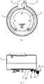
Fig. 1 is a plan view of an automatic water-adding vaporization pot according to a first embodiment of the present disclosure; -
Fig. 2 is a cross-sectional view of the automatic water-adding vaporization pot as shown inFig. 1 ; -
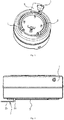
Fig. 3 is a perspective view of the automatic water-adding vaporization pot as shown inFig. 1 ; -
Fig. 4 is a cross-sectional view of an automatic water-adding vaporization pot according to a second embodiment of the present disclosure; -
Fig. 5 is a perspective view of an automatic water-adding vaporization pot according to a third embodiment of the present disclosure; -
Fig. 6 is a perspective view of an automatic water-adding vaporization pot according to a fourth embodiment of the present disclosure; -
Fig. 7 is a schematic circuit diagram of an automatic water-adding vaporization pot according to a fifth embodiment of the present disclosure; -
Fig. 8 is a cross-sectional view of an automatic water-adding vaporization pot according to a sixth embodiment of the present disclosure; -
Fig. 9 is a bottom view of the automatic water-adding vaporization pot according to the sixth embodiment of the present disclosure; -
Fig. 10 is a cross-sectional view of an automatic water-adding vaporization pot according to a seventh embodiment of the present disclosure; -
Fig. 11 is a schematic circuit diagram of an automatic water-adding vaporization pot according to an eighth embodiment of the present disclosure; -
Fig. 12 is a plan view of an automatic water-adding vaporization pot according to a ninth embodiment of the present disclosure; -
Fig. 13 is a cross-sectional view of the automatic water-adding vaporization pot according to a ninth embodiment of the present disclosure. - Referring to
Figs. 1-3 , an automatic water-adding vaporization pot of a first embodiment of the present disclosure provided includes apot body 1, aheating component 2 mounted on thepot body 1, a water pump connected with thepot body 1, a control circuit for controlling the water pump, a firsttemperature acquisition board 3 and a water-shortage andtemperature sensing element 5 mounted on the firsttemperature acquisition board 3. - More specifically, one
end 31 of the firsttemperature acquisition board 3 is connected with theheating component 2, theremaining parts 32 of thetemperature acquisition board 3 are away from thepot body 1, so that temperatures of thetemperature acquisition board 3 and thepot body 1 are not synchronous. For instance, when the temperature of thepot body 1 is decreased rapidly, the temperature of thetemperature acquisition board 3 may be decreased later or far more slowly than the decreased temperature of thepot body 1. The water-shortage andtemperature sensing element 5 is mounted at a position of the firsttemperature acquisition board 3 away from thepot body 1, and the water-shortage andtemperature sensing element 5 is connected with the control circuit. - A conventional temperature controller is generally directly mounted on the pot body, in other words, the temperature controller can detect a temperature of the pot body directly. When the pot body is filled with water, a temperature detected by the temperature controller is decreased quickly, and thus the temperature controller can detect the decreased temperature immediately (i.e. there is no delay for detecting the decreased temperature by the temperature controller), a duration of adding water to the water pump cannot be met. A conventional solution is to detect a water level with an electric contact, due to an influence of hard water, however, a detection accuracy is poor.
- In the embodiment of the present disclosure, the first
temperature acquisition board 3 plays a role of controlling a temperature-sensing. When a water quantity is decreased, an amount of heat transferred from theheating component 2 to the firsttemperature acquisition board 3 is increased, and thus the firsttemperature acquisition board 3 can be quickly heated up. The water-shortage andtemperature sensing element 5 detects a change of the temperature and controls the water pump to fill water into thepot body 1. Once thepot body 1 is filled with water, the temperature of thepot body 1 is decreased quickly. Due to a heat capacity of the firsttemperature acquisition board 3 and a temperature compensation effect of theheating component 2, however, the decreased internal temperature of the pot body influences the temperature of the firsttemperature acquisition board 3 with a delay, i.e. the firsttemperature acquisition board 3 may not be quickly cooled down, such that a dropped temperature of the firsttemperature acquisition board 3 is detected by the water-shortage andtemperature sensing element 5, after the temperature of thepot body 1 has been decreased a while. A duration of the delay equals to the duration of adding water of the water pump. The duration of adding water of the water pump can be calculated according to a volume of thepot body 1, and a mounting location of the water-shortage andtemperature sensing element 5 on the firsttemperature acquisition board 3 is determined accordingly. The water-shortage andtemperature sensing element 5 in the embodiment of the present disclosure is a temperature controller or a temperature sensitive resistor. By providing the water-shortage andtemperature sensing element 5 and the firsttemperature acquisition board 3, a function of continuous automatic water-adding may be achieved without any complicated control calculation, and a cost of the automatic water-adding vaporization pot is reduced. - The solution of the present disclosure is different from the conventional solution that the internal temperature of the pot body is directly measured by a temperature sensing element. In the embodiment of the present disclosure, the first
temperature acquisition board 3 is used as a reference for measuring temperature. Such indirect detection method for detecting temperature has adjustability and is favorable for adjustments of both a reference temperature and a measurement temperature of the temperature sensing element, so as to achieve the continuous water-adding. The firsttemperature acquisition board 3 in the embodiment of the present disclosure plays roles of both transferring and collecting heat. The firsttemperature acquisition board 3 plays a role of stable calibration for a temperature control element at an initial stage. During ordinary work, the firsttemperature acquisition board 5 has a stable temperature, which may better meet a requirement of the detection of the temperature sensing element. - Referring to
Fig. 1 , in the embodiment of the present disclosure, a running time of the water pump is depended on a heat transfer rate and a heat capacity of the firsttemperature acquisition board 3. The heat transfer rate and the heat capacity of the firsttemperature acquisition board 3 are depended on a mounting position, a volume and a shape of the firsttemperature acquisition board 3. The running time of the water pump is depended on relative positions between the firsttemperature acquisition board 3 and aninlet 12 of thepot body 1. The running time of the water pump may be adjusted by adjusting above parameters. - Referring to
Fig. 2 , in the embodiment of the present disclosure, the firsttemperature acquisition board 3 and theheating component 2 are formed integrally. Theheating component 2 in the embodiment of the present disclosure may be configured a heating plate, and the firsttemperature acquisition board 3 and theheating plate 2 may adopts a same material. Certainly, for the case of non-integral forming, the firsttemperature acquisition board 3 may also use other material, such as a metal material or a ceramic material. In the embodiment of the present disclosure, the firsttemperature acquisition board 3 and theheating plate 2 may be connected together by welding or bolt connection, in which the bolt connection means connecting the firsttemperature acquisition board 3 and theheating plate 2 by screw or bolt. - Referring to
Fig. 1 andFig. 3 , in the embodiment of the present disclosure, theheating plate 2 is provided with aheating tube 21, and the one end of the firsttemperature acquisition board 3 is located at theheating tube 21, such that the firsttemperature acquisition board 3 may promptly reflect a temperature change of theheating plate 2, thus exactly detecting the change of the temperature. - Referring to
Fig. 2 , in the embodiment of the present disclosure, the oneend 31 of the firsttemperature acquisition board 3 is bent and then connected with theheating plate 2, and an interval between the remainingpart 32 of the firsttemperature acquisition board 3 and thepot body 1 ranges from 0.5mm to 20mm. In this embodiment, the interval is 5mm. Since there is the above interval between the remainingpart 32 of the firsttemperature acquisition board 3 and thepot body 1, thepot body 1 may not directly contact the temperature sensing element. - Referring to
Fig. 1 , in the embodiment of the present disclosure, a mountinghole 33 is formed in thepart 32 of the firsttemperature acquisition board 3 away from thepot body 1, asupport member 34 is mounted in the mountinghole 33, and a bottom of thesupport member 34 is supported on thepot body 1. Thesupport member 34 may not only play a role of supporting for the firsttemperature acquisition board 3 but also be used as a connector for mounting the water-shortage and temperature sensing element. It is not easy for a deformation occurring to the remainingpart 32 of the firsttemperature acquisition board 3 away from thepot body 1 because of an existence of thesupport member 34. - Referring to
Fig. 4 , differences between a second embodiment of the present disclosure and the above embodiment are that the firsttemperature acquisition board 3 in the second embodiment is connected to thepot body 1, and a connecting position is in proximity to theheating body 2. Other structures, function and working principle of this embodiment are the same as the above embodiment. - Referring to
Fig. 5 , in a third embodiment of the present disclosure, a second temperature acquisition board 6 is further provided, and atemperature sensor 61 for controlling a steam pressure is mounted on the second temperature acquisition board 6. Because a temperature of the second temperature acquisition board 6 may exactly reflect the temperature of the heating plate, thetemperature sensor 61 may be promptly activated so as to make the steam pressure in the pot body stable. Other structures of this embodiment are identical with the above two embodiments. - In this embodiment, a second water-shortage and temperature sensing element may be also provided on the second temperature acquisition board 6, and the first water-shortage and
temperature sensing element 5 and the second water-shortage and temperature sensing element are configured for a high temperature detection and a low temperature detection respectively. A control for automatic water-adding is achieved by calculating a temperature difference or a temperature variation between the two water-shortage and temperature sensing elements. - Referring to
Fig. 6 , in a fourth embodiment of the present disclosure, the firsttemperature acquisition board 3 is provided with the water-shortage andtemperature sensing element 5 and atemperature sensor 61 for controlling the steam pressure. Because a temperature of the firsttemperature acquisition board 3 may exactly reflect the temperature of the heating plate, thetemperature sensor 61 may be promptly activated so as to make the steam pressure in the pot body stable. Other structures of this embodiment are identical with the above two embodiments. - Referring to
Fig. 7 , in a fifth embodiment of the present disclosure, other structures are the same as each embodiment described above, except that an on-off switch 23 is connected into apower supply circuit 22 of theheating component 2, and the on-off switch 23 and the water-shortage andtemperature sensing element 5 are linked. In this embodiment, the water-shortage andtemperature sensing element 5 is a double-throw temperature controller that has two groups of contacts simultaneously being activated, in which one group of contacts controls the running of the water pump and the other group of contacts controls thepower supply circuit 22 of theheating component 2 to work. This power supply circuit may enable theheating component 2 to go on working while the water pump is running. In the related art, if the pot body is short of water, theheating component 2 will stop working until the pot body is filled with water. In the present disclosure, theheating component 2 starts to heat while the water pump is working, which not only improve a generating speed of the steam, but also ensure a stability of the steam. - Certainly, other structures may also be applied in the present disclosure to enable the water-shortage and temperature sensing element to control the
heating component 2 to work. For example, when two water-shortage and temperature sensing elements are used, a high temperature water-shortage and temperature sensing element is connected into thepower supply circuit 22 of theheating component 2. Theheating component 2 is connected at the high temperature, and once the temperature is reduced, it switches to an ordinary power supply circuit. Certainly, a controller mode may also be used, such that once a controller receives an activation signal from the water-shortage and temperature sensing element, the controller controls theheating component 2 to work. - Referring to
Fig. 8 , in a sixth embodiment of the present disclosure, theheating component 2 is brazed to the bottom of thepot body 1. Moreover, in order to further improve a connecting stability between theheating component 2 and the bottom of thepot body 1, a plurality ofconnection elements 4 are disposed at the bottom of thepot body 1, and theheating component 2 is provided with throughholes 41 through which theconnection elements 4 penetrate, so that theheating component 2 is fastened to the bottom of thepot body 1 via theconnection elements 4. In the embodiment of the present disclosure, by using a combination connecting means of theconnection elements 4 and brazing, a slitting or desoldering caused by a creep between the heating component and the bottom of the pot body due to different coefficients of thermal expansion can be prevented, such that a connection between the heating plate and the pot body is closer, thus improving a thermal conduction efficiency. In the embodiment of the present disclosure, the connection elements are preseted at the bottom of the pot body, for example, theconnection elements 4 may be pre-welded at the bottom of the pot body, and the heating component is fixed at the bottom of the pot body by both fastening of theconnection elements 4 and brazing during assembling. - Referring to
Fig. 8 andFig. 9 , in above embodiment of the present disclosure, the plurality ofconnection elements 4 are arranged along a circumference or a rectangle, and the number of theconnection elements 4 is 4-20. In this embodiment, the plurality ofconnection elements 4 are arranged along the circumference and the number of theconnection elements 4 is 14. In this embodiment, theconnection elements 4 are arranged in inner and outer circles, and the heating tube of theheating component 2 is located between the two circles ofconnection elements 4. Theheating component 2 may be better secured without creep by such inner-and-outer-circles structure of theconnection elements 4. Certainly, the plurality ofconnection elements 4 may be also arranged at the bottom of the pot body uniformly in other pattern so as to make the heating component bear uniform force without creep. Theconnection elements 4 may be configured studs, one end of eachconnection element 4 is point welded to the bottom of thepot body 1, and the other end of eachconnection element 4 secures theheating component 2 via anut 42. The stud and nut are used for securing in this embodiment, each stud is point welded to the bottom of the pot body and secures the heating component via the nut. Certainly, other connection modes may be applied in the present disclosure. For example, the connection elements may also configured rivets, one end of each rivet is point welded to the bottom of the pot body, and the other end of each rivet is riveted to the heating component. A riveting structure is used in this mode. - In the embodiment of the present disclosure, the connection elements are provided between reinforcing ribs at the bottom of the pot body. With an aluminum sheet and a stainless steel for a screw fixing at the
connection elements 4 and a brazing solder penetration into the screw fixing, a reinforcing structure is formed at the connection elements. Firstly, the reinforcing structure at the connection elements reduces the creep of the aluminium sheet caused by different coefficients of thermal expansion. Secondly, a part of the bottom of the pot body between the reinforcing ribs and the connection elements may keep minimum deformation under a pressure of the pot body, and thus the heating tube is disposed at this part more stably, and an edge cracking of the aluminium sheet is reduced. - The structure of this embodiment described above is applicable for each embodiment described above, and remaining structures of this embodiment identical with each embodiment described above will not be described in detail herein.
- Referring to
Fig. 10 , in a seventh embodiment of the present disclosure, a reinforcing column 7 is disposed within thepot body 1, one end of the reinforcing column 7 is connected with an inner surface of a bottom of thepot body 1, and the other end of the reinforcing column 7 is connected with a top of thepot body 1. By providing the reinforcing column 7 in the embodiment of the present disclosure, a deformation of the pot body is reduced, such that the brazed heating component may not be cracked. Thepot body 1 in the embodiment of the present disclosure consists of anupper pot body 11 and alower pot body 12. A throughhole 13 with a flanging is formed inward at a top of theupper pot body 11. A top of the reinforcing column 7 is welded in the throughhole 13, and a bottom of the reinforcing column 7 is welded to an inner surface of a bottom of thelower pot body 12. Aspacer 14 is further disposed at the throughhole 13. Thespacer 14 is favorable for the welding of the reinforcing column 7 and plays a role of protection for theupper pot body 11. Agroove 71 is formed at the top and bottom of the reinforcing column 7 respectively. Thegroove 71 is favorable for the welding of the reinforcing column 7. With thegroove 71, the heat may be concentrated at a welding part during the welding, thus improving a welding efficiency and reducing a welding time. - The structure of this embodiment described above is applicable for each embodiment described above, and remaining structures of this embodiment identical with each embodiment described above will not be described in detail herein.
- Referring to
Fig. 11 , in an eighth embodiment of the present disclosure, aprotection circuit 8 for dry burning prevention is further provided. Theprotection circuit 8 for dry burning prevention comprises a PTCthermal protector 81 for sensing a dry burning temperature, and the PTCthermal protector 81 is connected with a heating control circuit of theheating component 2. In the embodiment of the present disclosure, contacts of the PTC thermal protector are connected in series in the heating control circuit of the heating component. When a temperature reaches the dry burning temperature, the PTC thermal protector is activated. In this case, a PTC heating element in the PTC thermal protector is on and heated, thus keeping the contacts of the PTC thermal protector always activated instead of resetting. Such PTC thermal protector may be purchased from a market. In the embodiment of the present disclosure, the PTC thermal protector is provided as a temperature controller for dry burning prevention, such that a heater may be not on and off repeatedly, thus extending service lives of related devices. In the embodiment of the present disclosure, the PTC thermal protector may also be mounted on the firsttemperature acquisition board 3, such that a dry burning signal can be exactly detected and the protection for the dry burning is timely. - The structure of this embodiment described above is applicable for each embodiment described above, and remaining structures of this embodiment identical with each embodiment described above will not be described in detail herein.
- Referring to
Fig. 12 andFig. 13 , in a ninth embodiment of the present disclosure, the firsttemperature acquisition board 3 is formed by a middle part of theheating component 2 which is protruded outward, and the firsttemperature acquisition board 3 is connected with theheating component 2 via a connectingleg 39. In this embodiment, the firsttemperature acquisition board 3 is formed by protruding the middle part of theheating component 2 outside, such that the firsttemperature acquisition board 3 is away from the pot body and plays the same role as that in each embodiment described above. By using such structure, an installation of each element is within a projection of the pot body, which is convenient for installation. Remaining structures of this embodiment are identical with each embodiment described above. - In this embodiment of the present disclosure, the first
temperature acquisition board 3 is connected with theheating component 2 via the connectingleg 39 located at one side. Moreover, the connectingleg 39 is configured for transferring heat. Therefore, a time period for transferring heat may be controlled by adjusting a size of the connectingleg 39. In this embodiment, both sides of the firsttemperature acquisition board 3 are connected with theheating component 2 via the connectinglegs 39, and the remaining parts of the firsttemperature acquisition board 3 are away from theheating component 2. Certainly, such outward protruding structure may be also replaced by an inward recessing of the pot body. A design that the connection elements are arranged in inner-and-outer-circles according to the sixth embodiment is used in this embodiment. Other structures may use a related structure of the embodiments described above or a combination thereof.
Claims (15)
- An automatic water-adding vaporization pot, comprising: a pot body (1), a heating component (2) mounted on the pot body, a water pump connected with the pot body, and a control circuit for controlling the water pump, wherein the automatic water-adding vaporization pot further comprises: a first temperature acquisition board (3) and a water-shortage and temperature sensing element (5) mounted on the first temperature acquisition board, and characterized in that one end (31) of the first temperature acquisition board is connected with the heating component or to a position of the pot body in proximity to the heating component, remaining parts (32) of the first temperature acquisition board are away from the pot body, the water-shortage and temperature sensing element is mounted at a position of the first temperature acquisition board away from the pot body, and the water-shortage and temperature sensing element is connected with the control circuit.
- The automatic water-adding vaporization pot according to claim 1, wherein a running time of the water pump is depended on a heat transfer rate and a heat capacity of the first temperature acquisition board.
- The automatic water-adding vaporization pot according to claim 2, wherein the heat transfer rate and the heat capacity of the first temperature acquisition board are depended on a mounting position, a volume and a shape of first the temperature acquisition board.
- The automatic water-adding vaporization pot according to claim 1, wherein the first temperature acquisition board and the heating component are formed integrally.
- The automatic water-adding vaporization pot according to claim 1, wherein the heating component is provided with a heating tube (21), and the one end of the first temperature acquisition board is located at the heating tube.
- The automatic water-adding vaporization pot according to claim 1, wherein the one end of the first temperature acquisition board is bent and then connected with the heating component, and an interval between the remaining part of the first temperature acquisition board and the pot body ranges from 0.5mm to 20mm.
- The automatic water-adding vaporization pot according to claim 1, wherein the first temperature acquisition board and the heating component are connected by welding or bolt connection.
- The automatic water-adding vaporization pot according to claim 1, wherein a mounting hole (33) is formed in the part of the first temperature acquisition board away from the pot body, a support member (34) is mounted in the mounting hole and has a bottom supported on the pot body.
- The automatic water-adding vaporization pot according to claim 1, further comprising a second temperature acquisition board (6), wherein a temperature sensor (61) for controlling a steam pressure is mounted on the second temperature acquisition board.
- The automatic water-adding vaporization pot according to claim 1, wherein the first temperature acquisition board is further provided with a temperature sensor for controlling a steam pressure.
- The automatic water-adding vaporization pot according to claim 1, wherein an on-off switch (23) is connected into a power supply circuit of the heating component, and the on-off switch and the water-shortage and temperature sensing element are linked.
- The automatic water-adding vaporization pot according to claim 1, wherein a plurality of connection elements (4) are disposed at a bottom of the pot body, and the heating component is provided with through holes (41) through which the connection elements penetrate, so as to be fixed via the connection elements and brazed on the bottom of the pot body.
- The automatic water-adding vaporization pot according to claim 1, wherein a reinforcing column (7) is disposed within the pot body, and has one end connected with an inner surface of a bottom of the pot body and the other end connected with a top of the pot body.
- The automatic water-adding vaporization pot according to claim 1, further comprising a protection circuit (8) for dry burning prevention, wherein the protection circuit for dry burning prevention comprises a PTC thermal protector (81) for sensing a dry burning temperature, and the PTC thermal protector is connected with a heating control circuit of the heating component.
- The automatic water-adding vaporization pot according to claim 1, wherein first the temperature acquisition board is formed by a middle part of the heating component protruded outward, and the temperature acquisition board is connected with the heating component (2) via a connecting leg (39).
Applications Claiming Priority (2)
| Application Number | Priority Date | Filing Date | Title |
|---|---|---|---|
| CN201210318454.4A CN103672836B (en) | 2012-08-31 | 2012-08-31 | A kind of automatic watering vaporizing pot |
| PCT/CN2013/001024 WO2014032400A1 (en) | 2012-08-31 | 2013-08-30 | Automatic water-adding vaporization pot |
Publications (3)
| Publication Number | Publication Date |
|---|---|
| EP2905534A1 EP2905534A1 (en) | 2015-08-12 |
| EP2905534A4 EP2905534A4 (en) | 2016-07-13 |
| EP2905534B1 true EP2905534B1 (en) | 2018-04-11 |
Family
ID=50182423
Family Applications (1)
| Application Number | Title | Priority Date | Filing Date |
|---|---|---|---|
| EP13833430.5A Not-in-force EP2905534B1 (en) | 2012-08-31 | 2013-08-30 | Automatic water-adding vaporization pot |
Country Status (5)
| Country | Link |
|---|---|
| US (1) | US9677757B2 (en) |
| EP (1) | EP2905534B1 (en) |
| CN (1) | CN103672836B (en) |
| RU (1) | RU2600481C1 (en) |
| WO (1) | WO2014032400A1 (en) |
Families Citing this family (6)
| Publication number | Priority date | Publication date | Assignee | Title |
|---|---|---|---|---|
| CN103672836B (en) * | 2012-08-31 | 2016-08-24 | 宁波新乐生活电器有限公司 | A kind of automatic watering vaporizing pot |
| CN205458000U (en) * | 2015-12-25 | 2016-08-17 | 佛山市顺德区爱德实业有限公司 | Multifunctional cooking pan |
| EP3540329B1 (en) | 2016-06-20 | 2021-04-28 | Bleckmann GmbH & Co. KG | Heating system component providing a compact temperature sensor design |
| US10598549B2 (en) * | 2016-08-04 | 2020-03-24 | The Vollrath Company, L.L.C. | Wireless temperature probe |
| US11134321B2 (en) | 2016-08-04 | 2021-09-28 | The Vollrath Company, L.L.C. | Wireless temperature probe |
| EP4009741A1 (en) * | 2020-12-03 | 2022-06-08 | Bleckmann GmbH & Co. KG | Heating system component for sensing a first and second temperature |
Family Cites Families (57)
| Publication number | Priority date | Publication date | Assignee | Title |
|---|---|---|---|---|
| US2437963A (en) * | 1943-03-24 | 1948-03-16 | Gen Electric | Method and apparatus for producing aerosols |
| US2561932A (en) * | 1949-01-06 | 1951-07-24 | Hudson Mfg Co H D | Float type immersion heater for tanks and the like |
| US2686863A (en) * | 1951-08-07 | 1954-08-17 | Edward F Chandler | Fluid heating and circulating device |
| US2785271A (en) * | 1953-10-08 | 1957-03-12 | Hal H Baly | Steam generator |
| SU366310A1 (en) * | 1971-12-20 | 1973-01-16 | ALL-UNION | |
| US4000396A (en) * | 1972-09-26 | 1976-12-28 | North American Systems, Inc. | Instant brewing pour-in instant electric coffee maker |
| US4455477A (en) * | 1980-04-16 | 1984-06-19 | Zip Heaters (Aust) Pty. Limited | Electric boiling water heater |
| US4460819A (en) * | 1983-01-11 | 1984-07-17 | Intropa Trading S.A. | Instantaneous flow-through electric water heater for coffee makers |
| EP0135611B1 (en) * | 1983-09-29 | 1987-09-09 | Trading Sa Intropa | Electric filter coffee machine |
| IT1185051B (en) * | 1985-03-08 | 1987-11-04 | E G O Italiana Spa | APPLIANCE FOR GENERATING STEAM, IN PARTICULAR FOR COOKING DEVICES |
| US4668854A (en) * | 1985-08-13 | 1987-05-26 | Napco Scientific Company | Humidification system |
| WO1987005681A1 (en) * | 1986-03-11 | 1987-09-24 | Riba Guenther | Steam generator |
| SU1373973A1 (en) * | 1986-08-05 | 1988-02-15 | Киевский институт автоматики им.ХХУ съезда КПСС | System for regulating temperature conditions and steam overheating of straight-through boiler unit |
| US4835366A (en) * | 1987-10-07 | 1989-05-30 | Allied Precision Industries, Inc. | Portable temperature controlled floating electric immersion heater for a livestock water tank |
| DE3941476A1 (en) * | 1989-12-15 | 1991-06-20 | Melitta Haushaltsprodukte | CONTINUOUS HEATERS, ESPECIALLY FOR MACHINES FOR THE PRODUCTION OF BREW BEVERAGES |
| GB2262422B (en) * | 1990-09-17 | 1995-04-05 | Strix Ltd | Immersion heaters |
| DE4130447A1 (en) * | 1991-09-13 | 1993-03-25 | Braun Ag | WATER BOILER |
| GB2302003B (en) * | 1995-06-07 | 2000-02-16 | West Bend Co | Improved heating device for a small appliance |
| FR2740537B1 (en) * | 1995-10-31 | 1998-01-16 | Seb Sa | STEAM GENERATOR WITH AUTOMATIC SUPPLY AND METHOD FOR MEASURING THE LIQUID LEVEL IN SUCH A GENERATOR |
| FR2755706B1 (en) * | 1996-11-13 | 1998-12-24 | Seb Sa | STEAM GENERATOR |
| ATE206193T1 (en) * | 1997-02-14 | 2001-10-15 | Ecovap S A | STEAM GENERATOR |
| US5933575A (en) * | 1998-03-19 | 1999-08-03 | Sanders; Clifton Omer | Water heating appliance for hottub or spa |
| EP1023866A1 (en) * | 1999-01-27 | 2000-08-02 | Euroflex S.r.l. | Easily portable linear-shaped steam generating unit |
| CN2531178Y (en) | 2001-10-26 | 2003-01-15 | 马有江 | Temperature control stop valve |
| US20030142965A1 (en) * | 2002-01-29 | 2003-07-31 | Kable Enterprises Co., Ltd. | Steam-cleaning appliance |
| JP3689760B2 (en) * | 2003-09-10 | 2005-08-31 | シャープ株式会社 | Steam generator and cooking device equipped with the same |
| US6915070B1 (en) * | 2004-09-03 | 2005-07-05 | Ming-Tsung Lee | Quick heater for drinking water |
| TR201906715T4 (en) * | 2004-12-22 | 2019-05-21 | Koninklijke Philips Nv | Steam boiler for use in a steam generating device. |
| FI117665B (en) * | 2005-08-10 | 2007-01-15 | F E M Ltd | Steam generator |
| ATE463990T1 (en) * | 2005-09-19 | 2010-04-15 | Koninkl Philips Electronics Nv | DEVICE FOR PRODUCING A DRINK USING A KETTLE |
| RU2426941C2 (en) * | 2005-12-19 | 2011-08-20 | Конинклейке Филипс Электроникс Н.В. | Steam generation plant and method |
| JP4252607B2 (en) * | 2006-07-26 | 2009-04-08 | シャープ株式会社 | Steam generator and cooking device |
| KR100825825B1 (en) * | 2006-12-13 | 2008-04-28 | 한경희 | Instant Heat Steam Boiler |
| EP1944404A1 (en) * | 2006-12-18 | 2008-07-16 | Koninklijke Philips Electronics N.V. | A device for supplying superheated water |
| EP1975308A1 (en) * | 2007-03-30 | 2008-10-01 | Koninklijke Philips Electronics N.V. | Method for determining the liquid level in a boiler |
| CN201094538Y (en) * | 2007-08-28 | 2008-08-06 | 甘跃斌 | Bottom structure of quick electric heating kettle |
| CN201184587Y (en) | 2007-11-05 | 2009-01-21 | 邵博言 | Steam boiler with automatic water-feeding control system |
| CN201139431Y (en) * | 2007-12-08 | 2008-10-29 | 方士达 | Electric heating container |
| GB0725235D0 (en) * | 2007-12-24 | 2008-02-06 | Strix Ltd | Liquid heating apparatus |
| CN100551307C (en) | 2008-05-20 | 2009-10-21 | 江苏科技大学 | Steam type electric heating blanket |
| US8867906B2 (en) * | 2008-11-07 | 2014-10-21 | General Electric Company | Dry fire protection system |
| CN101736567A (en) * | 2008-11-20 | 2010-06-16 | 厦门灿坤实业股份有限公司 | Explosive type steam-spray iron device |
| CN201429123Y (en) * | 2009-04-29 | 2010-03-24 | 夏云彪 | Electromagnetic oven with temperature acquisition board |
| CN101799153A (en) | 2009-07-09 | 2010-08-11 | 姜豪奎 | High efficiency steam generator and method for controlling water level thereof |
| CN201473803U (en) | 2009-08-21 | 2010-05-19 | 浙江华光电器集团有限公司 | Improved structure of steamer |
| ITFI20100112A1 (en) * | 2010-05-21 | 2011-11-22 | Koninkl Philips Electronics Nv | "DEVICE FOR WATER HEATING AND STEAM PRODUCTION" |
| CN201715680U (en) * | 2010-07-02 | 2011-01-19 | 佛山市顺德区兆坚电器制造有限公司 | Electric water heater |
| CN101925206B (en) | 2010-07-15 | 2013-02-27 | 李嘉琪 | An electric heating device and an electric heater using the electric heating device |
| CN202195572U (en) * | 2011-08-12 | 2012-04-18 | 杭州热威机电有限公司 | Heater combined with pump |
| CN202298269U (en) | 2011-10-09 | 2012-07-04 | 宁波新乐生活电器有限公司 | Improved large-capacity vaporizing pot |
| CN203338886U (en) * | 2011-12-20 | 2013-12-11 | 江苏神马电力股份有限公司 | 800kV gas insulation composite bushing |
| CN102637594B (en) * | 2012-03-19 | 2017-08-22 | 晶能光电(江西)有限公司 | The device and method of annealed alloy is carried out to epitaxial wafer |
| CN202835312U (en) * | 2012-08-31 | 2013-03-27 | 宁波新乐生活电器有限公司 | Vaporization pot with water automatically added |
| CN103672836B (en) * | 2012-08-31 | 2016-08-24 | 宁波新乐生活电器有限公司 | A kind of automatic watering vaporizing pot |
| CN202835311U (en) | 2012-08-31 | 2013-03-27 | 宁波新乐生活电器有限公司 | Electric heating liquid container |
| JP6010765B2 (en) * | 2013-03-14 | 2016-10-19 | パナソニックIpマネジメント株式会社 | Steam generator |
| DE202014011503U1 (en) * | 2013-07-25 | 2021-06-10 | Koninklijke Philips N.V. | Device for generating steam |
-
2012
- 2012-08-31 CN CN201210318454.4A patent/CN103672836B/en not_active Expired - Fee Related
-
2013
- 2013-08-30 WO PCT/CN2013/001024 patent/WO2014032400A1/en not_active Ceased
- 2013-08-30 EP EP13833430.5A patent/EP2905534B1/en not_active Not-in-force
- 2013-08-30 RU RU2015108129/06A patent/RU2600481C1/en not_active IP Right Cessation
- 2013-08-30 US US14/422,659 patent/US9677757B2/en not_active Expired - Fee Related
Non-Patent Citations (1)
| Title |
|---|
| None * |
Also Published As
| Publication number | Publication date |
|---|---|
| WO2014032400A1 (en) | 2014-03-06 |
| EP2905534A4 (en) | 2016-07-13 |
| RU2600481C1 (en) | 2016-10-20 |
| CN103672836B (en) | 2016-08-24 |
| US20150233573A1 (en) | 2015-08-20 |
| CN103672836A (en) | 2014-03-26 |
| EP2905534A1 (en) | 2015-08-12 |
| US9677757B2 (en) | 2017-06-13 |
Similar Documents
| Publication | Publication Date | Title |
|---|---|---|
| US9677757B2 (en) | Automatic water-adding vaporization pot | |
| US20110248020A1 (en) | Electromagnetic oven for barbecue | |
| CN220453741U (en) | A fast temperature-sensing panel with a heat-conducting cap that is not easy to loosen | |
| CN211269931U (en) | Double-heating-pipe cooking machine | |
| CN202835311U (en) | Electric heating liquid container | |
| CN209733584U (en) | Adjustable temperature control structure of chafing dish | |
| CN205053827U (en) | Electric pot | |
| CN102283571A (en) | Electric pressure cooker | |
| CN202835312U (en) | Vaporization pot with water automatically added | |
| CN103672837B (en) | A kind of electric liquid heating vessels | |
| CN211242947U (en) | Heating disc | |
| JP2510895Y2 (en) | Thermostat heat receiver | |
| CN206710918U (en) | A kind of temperature controller of electric-heating cooking utensil | |
| CN211242765U (en) | Cooking machine with overheat protection function | |
| CN110274701B (en) | A temperature sensor fixing device for an evaporating plate of a cooking appliance | |
| CN204734338U (en) | Electric water heating kettle | |
| CN201683706U (en) | Temperature control device of electric pressure cooker | |
| CN223262776U (en) | Temperature control structure applied to electric cooker | |
| CN223262773U (en) | Electric pan base | |
| CN205322058U (en) | Pan with bottom of a boiler temperature sensor | |
| CN203454083U (en) | Liquid electrical heating container | |
| CN210601762U (en) | An induction cooker with precise temperature control | |
| CN222086095U (en) | Temperature measuring components and smart cookers | |
| CN103054455A (en) | Split electric cooking pan | |
| CN205354955U (en) | Special temperature controller of oven class |
Legal Events
| Date | Code | Title | Description |
|---|---|---|---|
| PUAI | Public reference made under article 153(3) epc to a published international application that has entered the european phase |
Free format text: ORIGINAL CODE: 0009012 |
|
| 17P | Request for examination filed |
Effective date: 20150310 |
|
| AK | Designated contracting states |
Kind code of ref document: A1 Designated state(s): AL AT BE BG CH CY CZ DE DK EE ES FI FR GB GR HR HU IE IS IT LI LT LU LV MC MK MT NL NO PL PT RO RS SE SI SK SM TR |
|
| AX | Request for extension of the european patent |
Extension state: BA ME |
|
| DAX | Request for extension of the european patent (deleted) | ||
| RA4 | Supplementary search report drawn up and despatched (corrected) |
Effective date: 20160613 |
|
| RIC1 | Information provided on ipc code assigned before grant |
Ipc: F22B 1/28 20060101AFI20160607BHEP Ipc: F22D 5/26 20060101ALI20160607BHEP |
|
| GRAP | Despatch of communication of intention to grant a patent |
Free format text: ORIGINAL CODE: EPIDOSNIGR1 |
|
| STAA | Information on the status of an ep patent application or granted ep patent |
Free format text: STATUS: GRANT OF PATENT IS INTENDED |
|
| INTG | Intention to grant announced |
Effective date: 20170412 |
|
| GRAS | Grant fee paid |
Free format text: ORIGINAL CODE: EPIDOSNIGR3 |
|
| GRAA | (expected) grant |
Free format text: ORIGINAL CODE: 0009210 |
|
| STAA | Information on the status of an ep patent application or granted ep patent |
Free format text: STATUS: THE PATENT HAS BEEN GRANTED |
|
| AK | Designated contracting states |
Kind code of ref document: B1 Designated state(s): AL AT BE BG CH CY CZ DE DK EE ES FI FR GB GR HR HU IE IS IT LI LT LU LV MC MK MT NL NO PL PT RO RS SE SI SK SM TR |
|
| REG | Reference to a national code |
Ref country code: GB Ref legal event code: FG4D |
|
| REG | Reference to a national code |
Ref country code: CH Ref legal event code: EP |
|
| REG | Reference to a national code |
Ref country code: AT Ref legal event code: REF Ref document number: 988433 Country of ref document: AT Kind code of ref document: T Effective date: 20180415 |
|
| REG | Reference to a national code |
Ref country code: IE Ref legal event code: FG4D |
|
| REG | Reference to a national code |
Ref country code: DE Ref legal event code: R096 Ref document number: 602013035871 Country of ref document: DE |
|
| REG | Reference to a national code |
Ref country code: NL Ref legal event code: MP Effective date: 20180411 |
|
| REG | Reference to a national code |
Ref country code: LT Ref legal event code: MG4D |
|
| PG25 | Lapsed in a contracting state [announced via postgrant information from national office to epo] |
Ref country code: NL Free format text: LAPSE BECAUSE OF FAILURE TO SUBMIT A TRANSLATION OF THE DESCRIPTION OR TO PAY THE FEE WITHIN THE PRESCRIBED TIME-LIMIT Effective date: 20180411 |
|
| PG25 | Lapsed in a contracting state [announced via postgrant information from national office to epo] |
Ref country code: AL Free format text: LAPSE BECAUSE OF FAILURE TO SUBMIT A TRANSLATION OF THE DESCRIPTION OR TO PAY THE FEE WITHIN THE PRESCRIBED TIME-LIMIT Effective date: 20180411 Ref country code: BG Free format text: LAPSE BECAUSE OF FAILURE TO SUBMIT A TRANSLATION OF THE DESCRIPTION OR TO PAY THE FEE WITHIN THE PRESCRIBED TIME-LIMIT Effective date: 20180711 Ref country code: LT Free format text: LAPSE BECAUSE OF FAILURE TO SUBMIT A TRANSLATION OF THE DESCRIPTION OR TO PAY THE FEE WITHIN THE PRESCRIBED TIME-LIMIT Effective date: 20180411 Ref country code: PL Free format text: LAPSE BECAUSE OF FAILURE TO SUBMIT A TRANSLATION OF THE DESCRIPTION OR TO PAY THE FEE WITHIN THE PRESCRIBED TIME-LIMIT Effective date: 20180411 Ref country code: FI Free format text: LAPSE BECAUSE OF FAILURE TO SUBMIT A TRANSLATION OF THE DESCRIPTION OR TO PAY THE FEE WITHIN THE PRESCRIBED TIME-LIMIT Effective date: 20180411 Ref country code: ES Free format text: LAPSE BECAUSE OF FAILURE TO SUBMIT A TRANSLATION OF THE DESCRIPTION OR TO PAY THE FEE WITHIN THE PRESCRIBED TIME-LIMIT Effective date: 20180411 Ref country code: SE Free format text: LAPSE BECAUSE OF FAILURE TO SUBMIT A TRANSLATION OF THE DESCRIPTION OR TO PAY THE FEE WITHIN THE PRESCRIBED TIME-LIMIT Effective date: 20180411 Ref country code: NO Free format text: LAPSE BECAUSE OF FAILURE TO SUBMIT A TRANSLATION OF THE DESCRIPTION OR TO PAY THE FEE WITHIN THE PRESCRIBED TIME-LIMIT Effective date: 20180711 |
|
| PG25 | Lapsed in a contracting state [announced via postgrant information from national office to epo] |
Ref country code: RS Free format text: LAPSE BECAUSE OF FAILURE TO SUBMIT A TRANSLATION OF THE DESCRIPTION OR TO PAY THE FEE WITHIN THE PRESCRIBED TIME-LIMIT Effective date: 20180411 Ref country code: LV Free format text: LAPSE BECAUSE OF FAILURE TO SUBMIT A TRANSLATION OF THE DESCRIPTION OR TO PAY THE FEE WITHIN THE PRESCRIBED TIME-LIMIT Effective date: 20180411 Ref country code: HR Free format text: LAPSE BECAUSE OF FAILURE TO SUBMIT A TRANSLATION OF THE DESCRIPTION OR TO PAY THE FEE WITHIN THE PRESCRIBED TIME-LIMIT Effective date: 20180411 Ref country code: GR Free format text: LAPSE BECAUSE OF FAILURE TO SUBMIT A TRANSLATION OF THE DESCRIPTION OR TO PAY THE FEE WITHIN THE PRESCRIBED TIME-LIMIT Effective date: 20180712 |
|
| REG | Reference to a national code |
Ref country code: AT Ref legal event code: MK05 Ref document number: 988433 Country of ref document: AT Kind code of ref document: T Effective date: 20180411 |
|
| PG25 | Lapsed in a contracting state [announced via postgrant information from national office to epo] |
Ref country code: PT Free format text: LAPSE BECAUSE OF FAILURE TO SUBMIT A TRANSLATION OF THE DESCRIPTION OR TO PAY THE FEE WITHIN THE PRESCRIBED TIME-LIMIT Effective date: 20180813 |
|
| REG | Reference to a national code |
Ref country code: DE Ref legal event code: R097 Ref document number: 602013035871 Country of ref document: DE |
|
| PG25 | Lapsed in a contracting state [announced via postgrant information from national office to epo] |
Ref country code: SK Free format text: LAPSE BECAUSE OF FAILURE TO SUBMIT A TRANSLATION OF THE DESCRIPTION OR TO PAY THE FEE WITHIN THE PRESCRIBED TIME-LIMIT Effective date: 20180411 Ref country code: RO Free format text: LAPSE BECAUSE OF FAILURE TO SUBMIT A TRANSLATION OF THE DESCRIPTION OR TO PAY THE FEE WITHIN THE PRESCRIBED TIME-LIMIT Effective date: 20180411 Ref country code: CZ Free format text: LAPSE BECAUSE OF FAILURE TO SUBMIT A TRANSLATION OF THE DESCRIPTION OR TO PAY THE FEE WITHIN THE PRESCRIBED TIME-LIMIT Effective date: 20180411 Ref country code: AT Free format text: LAPSE BECAUSE OF FAILURE TO SUBMIT A TRANSLATION OF THE DESCRIPTION OR TO PAY THE FEE WITHIN THE PRESCRIBED TIME-LIMIT Effective date: 20180411 Ref country code: EE Free format text: LAPSE BECAUSE OF FAILURE TO SUBMIT A TRANSLATION OF THE DESCRIPTION OR TO PAY THE FEE WITHIN THE PRESCRIBED TIME-LIMIT Effective date: 20180411 Ref country code: DK Free format text: LAPSE BECAUSE OF FAILURE TO SUBMIT A TRANSLATION OF THE DESCRIPTION OR TO PAY THE FEE WITHIN THE PRESCRIBED TIME-LIMIT Effective date: 20180411 |
|
| PLBE | No opposition filed within time limit |
Free format text: ORIGINAL CODE: 0009261 |
|
| STAA | Information on the status of an ep patent application or granted ep patent |
Free format text: STATUS: NO OPPOSITION FILED WITHIN TIME LIMIT |
|
| PG25 | Lapsed in a contracting state [announced via postgrant information from national office to epo] |
Ref country code: IT Free format text: LAPSE BECAUSE OF FAILURE TO SUBMIT A TRANSLATION OF THE DESCRIPTION OR TO PAY THE FEE WITHIN THE PRESCRIBED TIME-LIMIT Effective date: 20180411 Ref country code: SM Free format text: LAPSE BECAUSE OF FAILURE TO SUBMIT A TRANSLATION OF THE DESCRIPTION OR TO PAY THE FEE WITHIN THE PRESCRIBED TIME-LIMIT Effective date: 20180411 |
|
| REG | Reference to a national code |
Ref country code: DE Ref legal event code: R119 Ref document number: 602013035871 Country of ref document: DE |
|
| 26N | No opposition filed |
Effective date: 20190114 |
|
| PG25 | Lapsed in a contracting state [announced via postgrant information from national office to epo] |
Ref country code: MC Free format text: LAPSE BECAUSE OF FAILURE TO SUBMIT A TRANSLATION OF THE DESCRIPTION OR TO PAY THE FEE WITHIN THE PRESCRIBED TIME-LIMIT Effective date: 20180411 |
|
| REG | Reference to a national code |
Ref country code: CH Ref legal event code: PL |
|
| GBPC | Gb: european patent ceased through non-payment of renewal fee |
Effective date: 20180830 |
|
| PG25 | Lapsed in a contracting state [announced via postgrant information from national office to epo] |
Ref country code: LU Free format text: LAPSE BECAUSE OF NON-PAYMENT OF DUE FEES Effective date: 20180830 Ref country code: LI Free format text: LAPSE BECAUSE OF NON-PAYMENT OF DUE FEES Effective date: 20180831 Ref country code: CH Free format text: LAPSE BECAUSE OF NON-PAYMENT OF DUE FEES Effective date: 20180831 |
|
| REG | Reference to a national code |
Ref country code: BE Ref legal event code: MM Effective date: 20180831 |
|
| PG25 | Lapsed in a contracting state [announced via postgrant information from national office to epo] |
Ref country code: SI Free format text: LAPSE BECAUSE OF FAILURE TO SUBMIT A TRANSLATION OF THE DESCRIPTION OR TO PAY THE FEE WITHIN THE PRESCRIBED TIME-LIMIT Effective date: 20180411 |
|
| PG25 | Lapsed in a contracting state [announced via postgrant information from national office to epo] |
Ref country code: DE Free format text: LAPSE BECAUSE OF NON-PAYMENT OF DUE FEES Effective date: 20190301 |
|
| PG25 | Lapsed in a contracting state [announced via postgrant information from national office to epo] |
Ref country code: FR Free format text: LAPSE BECAUSE OF NON-PAYMENT OF DUE FEES Effective date: 20180831 Ref country code: BE Free format text: LAPSE BECAUSE OF NON-PAYMENT OF DUE FEES Effective date: 20180831 |
|
| PG25 | Lapsed in a contracting state [announced via postgrant information from national office to epo] |
Ref country code: GB Free format text: LAPSE BECAUSE OF NON-PAYMENT OF DUE FEES Effective date: 20180830 |
|
| PG25 | Lapsed in a contracting state [announced via postgrant information from national office to epo] |
Ref country code: MT Free format text: LAPSE BECAUSE OF NON-PAYMENT OF DUE FEES Effective date: 20180830 |
|
| PG25 | Lapsed in a contracting state [announced via postgrant information from national office to epo] |
Ref country code: TR Free format text: LAPSE BECAUSE OF FAILURE TO SUBMIT A TRANSLATION OF THE DESCRIPTION OR TO PAY THE FEE WITHIN THE PRESCRIBED TIME-LIMIT Effective date: 20180411 |
|
| PG25 | Lapsed in a contracting state [announced via postgrant information from national office to epo] |
Ref country code: IE Free format text: LAPSE BECAUSE OF NON-PAYMENT OF DUE FEES Effective date: 20180830 Ref country code: MK Free format text: LAPSE BECAUSE OF NON-PAYMENT OF DUE FEES Effective date: 20180411 Ref country code: CY Free format text: LAPSE BECAUSE OF FAILURE TO SUBMIT A TRANSLATION OF THE DESCRIPTION OR TO PAY THE FEE WITHIN THE PRESCRIBED TIME-LIMIT Effective date: 20180411 Ref country code: HU Free format text: LAPSE BECAUSE OF FAILURE TO SUBMIT A TRANSLATION OF THE DESCRIPTION OR TO PAY THE FEE WITHIN THE PRESCRIBED TIME-LIMIT; INVALID AB INITIO Effective date: 20130830 |
|
| PG25 | Lapsed in a contracting state [announced via postgrant information from national office to epo] |
Ref country code: IS Free format text: LAPSE BECAUSE OF FAILURE TO SUBMIT A TRANSLATION OF THE DESCRIPTION OR TO PAY THE FEE WITHIN THE PRESCRIBED TIME-LIMIT Effective date: 20180811 |