EP2905507A2 - Thrust cylinder with offset drive screw - Google Patents
Thrust cylinder with offset drive screw Download PDFInfo
- Publication number
- EP2905507A2 EP2905507A2 EP14182817.8A EP14182817A EP2905507A2 EP 2905507 A2 EP2905507 A2 EP 2905507A2 EP 14182817 A EP14182817 A EP 14182817A EP 2905507 A2 EP2905507 A2 EP 2905507A2
- Authority
- EP
- European Patent Office
- Prior art keywords
- drive screw
- thrust rod
- housing
- longitudinal axis
- thrust
- Prior art date
- Legal status (The legal status is an assumption and is not a legal conclusion. Google has not performed a legal analysis and makes no representation as to the accuracy of the status listed.)
- Withdrawn
Links
- 239000007787 solid Substances 0.000 claims abstract description 10
- 238000004519 manufacturing process Methods 0.000 abstract description 14
- 239000000463 material Substances 0.000 abstract description 4
- 230000000712 assembly Effects 0.000 abstract description 3
- 238000000429 assembly Methods 0.000 abstract description 3
- 238000010276 construction Methods 0.000 description 13
- 229910000831 Steel Inorganic materials 0.000 description 2
- 230000008878 coupling Effects 0.000 description 2
- 238000010168 coupling process Methods 0.000 description 2
- 238000005859 coupling reaction Methods 0.000 description 2
- 238000000034 method Methods 0.000 description 2
- 239000010959 steel Substances 0.000 description 2
- 238000003466 welding Methods 0.000 description 2
- 229910000906 Bronze Inorganic materials 0.000 description 1
- 239000000853 adhesive Substances 0.000 description 1
- 230000001070 adhesive effect Effects 0.000 description 1
- 230000004075 alteration Effects 0.000 description 1
- 239000004411 aluminium Substances 0.000 description 1
- XAGFODPZIPBFFR-UHFFFAOYSA-N aluminium Chemical compound [Al] XAGFODPZIPBFFR-UHFFFAOYSA-N 0.000 description 1
- 229910052782 aluminium Inorganic materials 0.000 description 1
- 238000005452 bending Methods 0.000 description 1
- 239000010974 bronze Substances 0.000 description 1
- 239000000356 contaminant Substances 0.000 description 1
- 238000011109 contamination Methods 0.000 description 1
- KUNSUQLRTQLHQQ-UHFFFAOYSA-N copper tin Chemical compound [Cu].[Sn] KUNSUQLRTQLHQQ-UHFFFAOYSA-N 0.000 description 1
- 238000005520 cutting process Methods 0.000 description 1
- 238000006073 displacement reaction Methods 0.000 description 1
- 238000005553 drilling Methods 0.000 description 1
- 230000000694 effects Effects 0.000 description 1
- 239000000203 mixture Substances 0.000 description 1
- 230000004048 modification Effects 0.000 description 1
- 238000012986 modification Methods 0.000 description 1
- 230000004044 response Effects 0.000 description 1
Images

Classifications
-
- B—PERFORMING OPERATIONS; TRANSPORTING
- B23—MACHINE TOOLS; METAL-WORKING NOT OTHERWISE PROVIDED FOR
- B23Q—DETAILS, COMPONENTS, OR ACCESSORIES FOR MACHINE TOOLS, e.g. ARRANGEMENTS FOR COPYING OR CONTROLLING; MACHINE TOOLS IN GENERAL CHARACTERISED BY THE CONSTRUCTION OF PARTICULAR DETAILS OR COMPONENTS; COMBINATIONS OR ASSOCIATIONS OF METAL-WORKING MACHINES, NOT DIRECTED TO A PARTICULAR RESULT
- B23Q1/00—Members which are comprised in the general build-up of a form of machine, particularly relatively large fixed members
- B23Q1/03—Stationary work or tool supports
- B23Q1/035—Stationary work or tool supports with an array of longitudinally movable rods defining a reconfigurable support surface
-
- F—MECHANICAL ENGINEERING; LIGHTING; HEATING; WEAPONS; BLASTING
- F16—ENGINEERING ELEMENTS AND UNITS; GENERAL MEASURES FOR PRODUCING AND MAINTAINING EFFECTIVE FUNCTIONING OF MACHINES OR INSTALLATIONS; THERMAL INSULATION IN GENERAL
- F16H—GEARING
- F16H25/00—Gearings comprising primarily only cams, cam-followers and screw-and-nut mechanisms
- F16H25/18—Gearings comprising primarily only cams, cam-followers and screw-and-nut mechanisms for conveying or interconverting oscillating or reciprocating motions
- F16H25/20—Screw mechanisms
-
- F—MECHANICAL ENGINEERING; LIGHTING; HEATING; WEAPONS; BLASTING
- F16—ENGINEERING ELEMENTS AND UNITS; GENERAL MEASURES FOR PRODUCING AND MAINTAINING EFFECTIVE FUNCTIONING OF MACHINES OR INSTALLATIONS; THERMAL INSULATION IN GENERAL
- F16H—GEARING
- F16H25/00—Gearings comprising primarily only cams, cam-followers and screw-and-nut mechanisms
- F16H25/18—Gearings comprising primarily only cams, cam-followers and screw-and-nut mechanisms for conveying or interconverting oscillating or reciprocating motions
- F16H25/20—Screw mechanisms
- F16H2025/204—Axial sliding means, i.e. for rotary support and axial guiding of nut or screw shaft
-
- F—MECHANICAL ENGINEERING; LIGHTING; HEATING; WEAPONS; BLASTING
- F16—ENGINEERING ELEMENTS AND UNITS; GENERAL MEASURES FOR PRODUCING AND MAINTAINING EFFECTIVE FUNCTIONING OF MACHINES OR INSTALLATIONS; THERMAL INSULATION IN GENERAL
- F16H—GEARING
- F16H25/00—Gearings comprising primarily only cams, cam-followers and screw-and-nut mechanisms
- F16H25/18—Gearings comprising primarily only cams, cam-followers and screw-and-nut mechanisms for conveying or interconverting oscillating or reciprocating motions
- F16H25/20—Screw mechanisms
- F16H2025/2062—Arrangements for driving the actuator
- F16H2025/2075—Coaxial drive motors
-
- Y—GENERAL TAGGING OF NEW TECHNOLOGICAL DEVELOPMENTS; GENERAL TAGGING OF CROSS-SECTIONAL TECHNOLOGIES SPANNING OVER SEVERAL SECTIONS OF THE IPC; TECHNICAL SUBJECTS COVERED BY FORMER USPC CROSS-REFERENCE ART COLLECTIONS [XRACs] AND DIGESTS
- Y10—TECHNICAL SUBJECTS COVERED BY FORMER USPC
- Y10T—TECHNICAL SUBJECTS COVERED BY FORMER US CLASSIFICATION
- Y10T74/00—Machine element or mechanism
- Y10T74/18—Mechanical movements
- Y10T74/18568—Reciprocating or oscillating to or from alternating rotary
- Y10T74/18576—Reciprocating or oscillating to or from alternating rotary including screw and nut
- Y10T74/18648—Carriage surrounding, guided by, and primarily supported by member other than screw [e.g., linear guide, etc.]
Definitions
- the present invention relates generally to actuators, and more particularly to linear actuators having particular application in a holding fixture, and more particularly in a holding fixture capable of holding a predetermined contoured workpiece such as an aircraft skin panel.
- Reconfigurable fixtures have been used for holding large area workpieces in a proper position for manufacturing.
- Such fixtures have included a planar array of linear actuators including thrust rods that can be controllably extended collectively to define a contoured support surface for a large area workpiece such as an aircraft skin panel.
- the ends of the thrust rods may be equipped with holding devices such as suction cups for holding the workpiece to the thrust rods.
- the linear actuators typically included a screw and nut drive assembly for extending and retracting a tubular thrust rod relative to an actuator housing.
- the tubular thrust rod and screw were coaxial, with the drive screw extending into the hollow interior of the tubular thrust rod.
- the tubular thrust rod was replaced by a circumferential arrangement of four smaller but solid thrust rods connected between the nut member that was driven by rotation of the screw and an end plate at the opposite end of the thrust rods.
- the drive nut member was guided by a plurality of guide rods mounted between opposite end plates of the housing.
- the four smaller thrust rods were each separately sealed, in contrast to a single seal for the tubular thrust rod.
- the present invention provides a linear actuator having particular application for reconfigurable fixtures used to hold large area workpieces.
- the linear actuators include a thrust rod connected to a translatable nut member that is driven by a rotatable drive screw that has a longitudinal axis off-set from the longitudinal axis of the thrust rod that preferably is centrally disposed within the housing of the actuator.
- the off-set axis of the drive screw enables the drive screw per unit size to handle greater loads and run at higher speeds.
- the use of a solid thrust rod enables the thrust rod per unit size to handle greater loads and be less expensive as opposed to being hollow when the drive screw is coaxial with the thrust rod. This arrangement also enables less material to be used to manufacture the linear actuator per unit size.
- the linear actuators may be used as an alternative to existing assemblies with central thrust rods.
- the invention therefore provides a linear actuator including a housing, a thrust rod disposed centrally within the housing and having an end portion extending from an end of the housing, the thrust rod having a longitudinal axis, a rotatable drive screw disposed within the housing and having a longitudinal axis parallel to the longitudinal axis of the thrust rod, and a translatable nut member disposed within the housing in threaded engagement with the drive screw and connected to the thrust rod for longitudinal movement therewith, the translatable nut member being driven upon rotation of the drive screw along the longitudinal axis of the drive screw, and wherein the drive screw is radially outwardly offset from the centrally disposed thrust rod.
- the invention also provides a linear actuator including a housing having a longitudinal centre axis, a thrust rod disposed within the housing and having an end portion extending from an end of the housing, the thrust rod having a longitudinal axis, a rotatable drive screw disposed within the housing and having a longitudinal axis parallel to and offset from the longitudinal centre axis of the housing, and a translatable nut member disposed within the housing in threaded engagement with the drive screw and connected to the thrust rod for longitudinal movement therewith, the translatable nut member being driven upon rotation of the drive screw along the longitudinal axis of the drive screw.
- the invention also provides a linear actuator including a housing having a longitudinal centre axis, a thrust rod disposed within the housing and having an end portion extending from an end of the housing, the thrust rod having a longitudinal axis, a rotatable drive screw disposed within the housing and having a longitudinal axis parallel to the longitudinal axis of the thrust rod, a translatable nut member disposed within the housing in threaded engagement with the drive screw and connected to the thrust rod for longitudinal movement therewith, the translatable nut member being driven upon rotation of the drive screw along the longitudinal axis of the drive screw, and an anti-rotation guide extending along a length of the housing parallel to the longitudinal axis of the drive screw, the anti-rotation guide being located at a side of the thrust rod diametrically opposite the drive screw.
- opposite ends of the drive screw are rotatably supported by respective bearings fixed in the housing.
- the linear actuator includes an anti-rotation guide configured to prevent rotation of the translatable nut member about the longitudinal axis of the drive screw relative to the housing.
- the anti-rotation guide includes a rod extending between opposite ends of the housing and on which the translatable nut member slides.
- the anti-rotation guide is disposed on a side of the thrust rod diametrically opposite the drive screw.
- the translatable nut member includes a thrust plate to which the thrust rod is attached and a nut attached to the thrust plate.
- the longitudinal axis of thrust rod is concentric with the longitudinal axis of the housing.
- the thrust rod is movable between a fully retracted position and a fully extended position, and wherein the extent of the thrust rod that is housed within the housing when in the retracted position of the thrust rod has a solid cross-section.
- the linear actuator includes a motor coupled to the drive screw, preferably with the rotational axis of the motor coaxial with the longitudinal axis of the drive screw.
- a reconfigurable fixture comprising a base and a plurality of the linear actuators of any above aspect mounted to the base, preferably with the actuators disposed parallel with respect to one another.
- the thrust rods of a plurality of the linear actuators are equipped with holding devices such as suction cups for holding the workpiece to the thrust rods.
- the drive screw includes a reduced diameter portion at an end of the drive screw.
- the invention has application to linear actuators, such as electromechanical linear actuators, for effecting movement of manufacturing components, such as manufacturing workpieces, tools, or tool holders, and thus will be described below chiefly in this context.
- linear actuator such as electromechanical linear actuators
- Such a linear actuator may be suitable for raising, lifting, or otherwise moving or supporting a manufacturing component.
- the invention can also be useful in other applications where it is desirable to effect movement, such as in construction equipment, gate operation, etc.
- Fig. 1 shows a manufacturing set up 10, in particular a reconfigurable fixture.
- the fixture includes a plurality of linear actuators 12 for raising and/or supporting a workpiece 14, such as an aircraft wing.
- the linear actuators 12 are secured, such as bolted, to a base surface, such as a work table 16.
- a portion of the actuators extend vertically therefrom to raise and thereafter maintain a raised height of the workpiece 14, or more particularly respective regions of the workpiece 14 for various manufacturing operations, such as cutting or drilling operations.
- the extension of the linear actuators can be varied to fit the contour of the workpiece 14 or to determine the contour of the workpiece 14.
- the rod ends of the linear actuators may be equipped with suction devices for holding respective portions of the workpiece surface to the rod ends.
- Figs. 2 to 6 show one of the linear actuators 12, which includes an actuator housing 20, a thrust rod 22 for extending and retracting in relation to the actuator housing 20, a drive screw assembly 24 disposed within the actuator housing 20, and an anti-rotation guide 26 for preventing rotation of the thrust rod relative to the drive screw assembly 24.
- Rotational movement of the drive screw assembly 24 is translated into axial movement of the thrust rod 22 relative to the actuator housing 20.
- the thrust rod 22 is caused to move axially along a longitudinal axis, such as longitudinal axis A of the thrust rod 22 and the actuator housing 20.
- the actuator housing 20 has a tubular portion or sleeve 32 that extends axially between a first end 34 and a second end 36 of the actuator housing. Located at the first and second ends 34 and 36 of the housing are a proximal end wall 40 and a distal end wall 42, respectively.
- the end walls 40 and 42 are formed by end caps.
- the end caps 40 and 42 are secured to and close the ends of the tubular portion 32.
- the end caps 40 and 42 are held to the ends of the tubular portion by tie bars 43 and associated nuts 44, although other suitable attachment means may be used.
- the sleeve 32 may be circular in cross-section and the end walls may be generally square in cross-section such that the corners of the end walls project beyond the sleeve. These projecting corners may have formed therein holes through which the ends of the tie bars extend.
- the actuator housing 20 may be made of aluminium, steel, or another suitable material.
- the actuator housing 20 may be of a length, width, and height to receive a substantial extent of the thrust rod 22 when the thrust rod 22 is retracted into the housing interior 32.
- the thrust rod 22 extends axially along the longitudinal axis A through an opening 54 in the distal end wall 42 concentric with the longitudinal axis A for securing the thrust rod 22 from lateral movement and allowing axial movement through it.
- the thrust rod 22 has a proximal end 60 and a distal end 62 that may include a mount for a holding component, such as a suction cup.
- the length of the thrust rod 22 from the proximal end 60 to the distal end 62 is illustrated as a solid (i.e., non-hollow) rod.
- the thrust rod 22 being solid allows less expensive manufacturing of the thrust rod 22 because manufacturing steps can be avoided. For example, the manufacturing steps to hollow-out a substantial portion of the thrust rod 22, as well as the manufacturing steps to provide a precise and smooth surface inside the thrust rod 22 for a radial bearing to slide within are not necessary.
- the proximal end 62 does not include any opening concentric with the thrust rod 22. More preferably, less than 10% of the thrust rod 22 is hollow.
- the thrust rod 22 may be a cylindrical rod, entirely solid (i.e., non-hollow), substantially solid (i.e., substantially non-hollow), hollow, or of any other suitable shape and cross-section. Further, the thrust rod 22 may be made of steel or another suitable material.
- the distal end 62 of the thrust rod 22 is extendable toward and away from the distal end 42 of the actuator housing 20.
- An intermediate portion of the thrust rod 22 is supported during axial movement of the thrust rod 22 to prevent lateral movement by a bearing 64 coaxial with the longitudinal axis A.
- the bearing 64 is shown as a bushing disposed in the distal end wall 42 of the actuator housing 20 and may be any other suitable bearing, such as a radial rod bearing, a slider bearing, or another type of bushing.
- the bearing 64 may slidably engage an outer circumference 66 of the thrust rod 22, thus supporting the thrust rod 22 about its outer circumference 66.
- the bearing 64 may seal against the outer circumference 66 to prevent contaminants from entering the actuator housing 20. Otherwise, a seal or wiper may be used to prevent contamination during actuation.
- the thrust rod 22 is driven into and out of the housing 20 by the drive screw assembly 24.
- the drive screw assembly 24 is rotatably attached to the proximal and distal end walls 40 and 42.
- the drive screw assembly 24 is attached at locations laterally spaced from the longitudinal axis A and the thrust rod 22. Laterally spacing the drive screw assembly allows the thrust rod 22 to be solid (i.e., non-hollow) at the proximal end 60 because the no portion of the drive screw assembly 24 needs to be located within the thrust rod 22.
- the drive screw assembly 24 may urge the thrust rod 22 to rotate relative to the actuator housing 20 or the drive screw assembly 24. Maintaining axial movement allows the thrust rod 22 to extend and retract more easily into a desired position without jamming the thrust rod 22 against bearing 64 or jamming the drive screw assembly 24.
- the drive screw assembly 24 includes a rotatable drive screw 70 disposed in the actuator housing 20 and a translatable nut member 72 with inner threads that engage with the drive screw 70.
- the drive screw 70 and translatable nut member 72 may be components of any suitable rotational movement to axial movement device, such as a ball screw assembly or of a roller screw assembly. As the drive screw 70 rotates the translatable nut member 72 is driven axially and thereby drives the thrust rod 22 axially.
- the drive screw 70 extends axially along a longitudinal axis B of the drive screw 70 and includes outer threads 74 between the first end 86 and the second end 90 of the drive screw 70.
- Rotational movement of the drive screw 70 causes the translatable nut member 72 to be translated along the centre longitudinal axis B of the drive screw 70 relative to the rotational movement of the drive screw 70.
- the longitudinal axis A, the thrust rod 22 and the actuator housing 20 may be coincident and the longitudinal axis B is off-set from the thrust rod 22.
- rotational movement of the drive screw 70 may cause the translatable nut member 72 to be driven axially along the longitudinal axis A of the actuator housing 20.
- axial movement of the thrust rod 22 coupled to the translatable nut member 72 may be effected, the axial movement of the thrust rod 22 also being along the centre axis of the actuator housing.
- the drive screw 70 extends between the proximal and distal end walls 40 and 42.
- a first end 86 of the drive screw 70 is disposed within the proximal end wall 40 and a second end 90 is disposed within the distal end wall 42.
- a portion of at least one of the first end 86 or the second end 90 abuts a portion of the actuator housing 20.
- the drive screw 70 is radially outwardly spaced from the thrust rod 22 and the longitudinal axis A relative to the actuator housing 22.
- the thrust rod 22 is radially inwardly spaced from the drive screw 70 relative to the actuator housing 22 to allow the thrust rod 22 to be concentric with the actuator housing 20 and the drive screw 70 to be adjacent the tubular portion 32 of the actuator housing 20.
- the drive screw 70 is adjacent to the tubular portion 32 and journalled in the proximal end wall 40 and the distal end wall 42 by suitable means such as a bearing 76 and a bearing 78.
- the first end 86 of the drive screw 70 may be supported against radial and/or axial movement by the bearing 76, such as a radial bearing, a radial screw bearing, an angular contact bearing, or a thrust bearing.
- the bearing 76 is disposed within the proximal end wall 40. Alternatively, the end wall may form at least a portion of the bearing 76.
- the first end 86 is coupled to a drive shaft of a motor 52.
- the bearing 76 can be mounted in the proximal end wall 40 or otherwise in the actuator housing 20.
- the second end 90 of the drive screw 70 may be supported by the bearing 78.
- the bearing 78 may be coupled, such as rotatably journalled, to an axially extending reduced diameter portion 88 of the drive screw 70 at the second end 90.
- the drive screw 70 may be rotatably connected to the bearing 78 disposed at the second end 86 within the distal end wall 42 to facilitate holding the drive screw 70 in tension to counter a buckling force caused by load on the thrust rod 22 exerting force on the translatable nut member 72 and buckling of the drive screw 70.
- the end wall may form at least a portion of the bearing.
- the bearing 78 may be any suitable type of bearing, preferably an angular contact bearing or a thrust bearing, less preferably a radial bearing, bushing, or any other suitable bearing. Use of a bearing type able to support an axial load allows the drive screw 70 to be put into tension by holding the second end 90 of the drive screw 70 with a bearing that allows the drive screw 70 to be held.
- Holding the drive screw 70 in tension prevents buckling of the drive screw 70 and allows better performance and longer life.
- the tension also allows a drive screw 70 with a smaller diameter to operate at the same load and speed as a larger diameter drive screw without such tension.
- the motor 52 may attach to the distal end wall 42, which may be located lower relative to the centre of the earth than the proximal end wall 40 to put the drive screw 70 in tension.
- the motor 52 drives the drive screw 70 and may be a rotary motor or any other suitable type of prime mover.
- the motor 52 may be coupled to the proximal end wall 40 for securing the motor 52 against rotational movement relative to the actuator housing 20.
- the proximal end wall 40 may have a first opening 50 for allowing coupling of the drive screw assembly 24 to the motor 52.
- the motor has a drive shaft that is parallel with, but not coaxial with the drive screw.
- rotational motion of the drive screw 70 may be provided by any other suitable method at the first end 86 opposite the second end 90.
- the reduced diameter portion 88 extends axially away from the first end 86 and is coaxial with the longitudinal axis B.
- the reduced diameter portion 88 engages the bearing 78 and allows positioning the drive screw 70 closer to the thrust rod 22. Positioning the drive screw 70 closer allows the overall footprint of the linear actuator to be reduced.
- the reduced diameter portion 88 may be less than 50% an average diameter of the drive screw 70 to reduce the footprint of the linear actuator 12 while still allowing the drive screw 70 to drive the thrust rod 22 through the translatable nut member 72.
- the translatable nut member 72 includes a thrust/guide plate 92 (which may be referred to as a "guide ring” or “piston”) and a nut 94 with inner threads that engage with the drive screw 70.
- the outer threads 74 of the drive screw 70 allow threaded engagement with the nut 94.
- the nut 94 includes inner threads 108, shown in Fig. 6 , for engaging the drive screw 70.
- the inner threads 108 may be formed of fixed threads or formed by ball bearings.
- the nut may be a ball screw nut that circulates ball bearings to smoothly translate along the drive screw 70.
- the nut may couple the thrust rod 22 to the drive screw 70, either directly or indirectly, the thrust rod 22 to translate axially in response to rotational movement of the drive screw 70.
- the nut 94 and the thrust rod 22 may be directly coupled, such as fixedly attached via threaded engagement, welding, adhesives, or other suitable method.
- the thrust/guide plate 92 may have threads for engaging the drive screw.
- the thrust/guide plate 92 is a cylindrical portion with a radially outward facing surface facing the actuator housing 20 and includes an axially facing surface 96 connected to the nut 94, a drive screw passage 100 parallel to the longitudinal axis A, and an anti-rotation guide passage 102 parallel to the longitudinal axis A.
- the thrust/guide plate 92 forms one-piece with the thrust rod 22.
- the thrust rod is connected to the thrust/guide plate 92 in any suitable manner, such as bolting or welding.
- the drive screw assembly 24 can be slidably coupled to the anti-rotation guide 26 without abutting the actuator housing to prevent rotational movement of the thrust rod.
- the anti-rotation guide 26 prevents rotation of the thrust rod 22 and allows the thrust rod 22 to maintain alignment with the longitudinal axis A and only move axially along the longitudinal axis A.
- the anti-rotation guide 26 extends axially between the proximal and distal end walls 40 and 42.
- the anti-rotation guide 26 is connected to the first and second ends 34 and 36 at locations laterally spaced from the longitudinal axis A and diametrically opposite the locations connecting the drive screw assembly 24.
- the anti-rotation guide may extend partially between the first and second ends 34 and 36. In one construction, the anti-rotation guide 26 is not diametrically opposite the locations connecting the drive screw assembly 24 to the actuator housing 20.
- the anti-rotation guide 26 may be laterally spaced from the longitudinal axis A and opposite the locations connecting the drive screw assembly 24 in any suitable location to prevent rotation of the thrust rod 22 relative to the drive screw assembly 24.
- an anti-rotation guide and the corresponding anti-rotation guide passage are not present and the drive screw alone prevents rotation of the thrust tube relative to the drive screw assembly.
- the proximal end 60 of the thrust rod is supported against radial movement via a portion of the thrust/guide plate 92 abutting an inner wall of the actuator housing 20 and the anti-rotation guide 26 slidably coupling to the thrust/guide plate 92.
- the anti-rotation guide passage 102 slides along the anti-rotation guide 26 while the drive screw passage 100 slides along or adjacent to the drive screw 70.
- the drive screw passage 100 is illustrated as generally cylindrical, axially extending, without threading, and laterally off-set from the thrust rod 22 to engage the drive screw 70.
- a screw bearing may be disposed within the drive screw passage 100 to support the drive screw 70.
- the drive screw passage has inner threading to engage the drive screw. Threading the drive screw passage allows the drive screw 70 to drive the thrust rod 22 without a nut. Threading the drive screw passage 100 also allows the drive screw passage 100 to receive the force otherwise applied to the nut 94 when being driven parallel to the anti-rotation guide passage 102 by the drive screw 70.
- the anti-rotation guide passage 102 is illustrated as generally cylindrical, axially extending, and laterally off-set from the drive screw passage to slidably connect with the anti-rotation rod 26.
- a bearing 106 is disposed within the anti-rotation guide passage 102. The bearing 106 allows a tight slidable connection between the anti-rotation guide passage 102 and the anti-rotation rod 26.
- the anti-rotation guide passage 102 is disposed at a radially outward portion of the thrust/guide plate 92 to engage an axially extending radially inward facing protrusion connected to the actuator housing to prevent rotational movement of the thrust rod 22.
- the anti-rotation guide passage is part of a radially inward facing portion of the actuator housing and engages a radially outward extending protrusion of the thrust/guide plate 92 to prevent rotational movement of the thrust rod 22.
- the thrust rod 22 extends and retracts to a desired position.
- the motor 52 drives the drive screw 70, which in turn drives the translatable nut member 72.
- the translatable nut member 72 moves axially along the drive screw 70 to drive the thrust rod 22.
- the anti-rotation guide 26 prevents rotation of the translatable nut member 72 relative to the anti-rotation guide 26 and allows the translatable nut member 72 to move axially along the anti-rotation guide 26 to position the thrust rod 22.
- the thrust rod 22 may support a workpiece statically. For example, when the thrust rod 22 is in a desired position, a workpiece may be placed at the distal end 62 of the thrust rod to support the workpiece in place.
- a plurality of linear actuators 12 may each include a thrust rod that is positioned based on a relative position of each linear actuator of the plurality of linear actuators 12.
- the thrust rods of each of the plurality of linear actuators may be positioned collectively form the shape of a contour of the workpiece 14.
- the thrust rod 22 may be extended or retracted after the workpiece 14 is placed at the distal end 62.
- the thrust rod 22 is dynamically loaded.
- the thrust rod 22 may be moved to re-position an already supported workpiece or additional load may be placed on the thrust rod 22 during manufacturing.
- the thrust rod 22 is used to position components outside of the manufacturing context.
- the thrust rod 22 may retract or extend a door or wing on a vehicle while the vehicle is in use.
- Figs. 7 and 8 show another linear actuator 212 which is substantially the same as the linear actuator 12 discussed above.
- the same reference numerals but indexed by 200 respectively are used to denote structures corresponding to similar structures in the linear actuator 212.
- the description of the linear actuator 12 set out above is equally applicable to the linear actuator 212 except as noted below.
- aspects of the linear actuators may be substituted for one another or used in conjunction with one another where applicable.
- Figs. 7 and 8 show a linear actuator 212 including an actuator housing 220, a thrust rod 222 for extending and retracting in relation to the actuator housing 220 and having outer threads 320, a drive screw assembly 224 disposed within the actuator housing 220, an anti-rotation guide 226 for preventing rotation of the thrust rod relative to the drive screw assembly 224, and a bearing 264 for slidably engaging thrust rod 222.
- the drive screw assembly 224 includes a rotatable drive screw 270 disposed in the actuator housing 220 and a translatable nut member 272 with inner threads that engage with the drive screw 270.
- the drive screw 270 engages a bearing 276 that is held in place by a nut 318.
- the bearing 276 may be any suitable bearing, such as an angular contact bearing.
- the nut 318 engages the drive screw 270 to axially abut the bearing 276 and prevent axial movement relative to the drive screw 270.
- the nut 318 may be any suitable nut, such as a lock nut.
- an axially facing portion of a motor 252 abuts the bearing 276 to hold the bearing 276 in place.
- the translatable nut member 272 is driven axially and thereby drives the thrust rod 222 axially.
- the translatable nut member 272 includes a thrust/guide plate 292 (which may be referred to as a "guide ring” or “piston”) with inner threads 322 that engage with the outer threads 320 of the thrust rod 222 and a nut 294 with inner threads that engage with the drive screw 270.
- the inner threads 322 extend concentrically with the outer threads 320 to prevent axial movement of the thrust rod 222 relative to the thrust/guide plate 292.
- the thrust/guide plate 292 engages with and axially translates with the nut 294.
- the thrust/guide plate 292 has inner threads 324 that engage with and are coaxial with outer threads 326 of the nut 294 to prevent the thrust/guide plate 292 from relative axial movement relative to the nut 294.
- the thrust/guide plate 292 further includes a bearing 330 coaxial with the anti-rotation guide 226.
- the bearing 330 allows the thrust/guide plate 292 to translate axially along the anti-rotation guide 226 and also engages the anti-rotation guide 226 to prevent radial movement of the thrust/guide plate 292 relative to the anti-rotation guide 226.
- the anti-rotation guide 226 includes a first engagement portion 332 and a second engagement portion 334 at opposite ends of the anti-rotation guide 226 for radially fixing the anti-rotation guide 226 to the actuator housing 220.
- the first and second engagement portions 332 and 334 are illustrated as axially extending cavities. Alternatively, at least one of the first and second engagement portions may include a protruding portion that engages a corresponding cavity within the actuator housing.
- the bearing 264 extends axially outside of the actuator housing 220. Extending the bearing 264 axially outside allows greater support of the thrust rod 222 to prevent radial bending of the thrust rod 222. Greater than 60% of a length of the bearing 264 extends axially outside of the actuator housing 220. In one construction, 60% or less of the bearing 264 extends axially outside of the actuator housing 220 to allow greater displacement length of the thrust rod 22.
- the bearing 264 may be any suitable bearing, such as a bushing, preferably a two-piece bronze bushing.
Landscapes
- Engineering & Computer Science (AREA)
- General Engineering & Computer Science (AREA)
- Mechanical Engineering (AREA)
- Transmission Devices (AREA)
Abstract
Description
- The present invention relates generally to actuators, and more particularly to linear actuators having particular application in a holding fixture, and more particularly in a holding fixture capable of holding a predetermined contoured workpiece such as an aircraft skin panel.
- Reconfigurable fixtures have been used for holding large area workpieces in a proper position for manufacturing. Such fixtures have included a planar array of linear actuators including thrust rods that can be controllably extended collectively to define a contoured support surface for a large area workpiece such as an aircraft skin panel. The ends of the thrust rods may be equipped with holding devices such as suction cups for holding the workpiece to the thrust rods.
- The linear actuators typically included a screw and nut drive assembly for extending and retracting a tubular thrust rod relative to an actuator housing. The tubular thrust rod and screw were coaxial, with the drive screw extending into the hollow interior of the tubular thrust rod. In another known linear actuator, the tubular thrust rod was replaced by a circumferential arrangement of four smaller but solid thrust rods connected between the nut member that was driven by rotation of the screw and an end plate at the opposite end of the thrust rods. The drive nut member was guided by a plurality of guide rods mounted between opposite end plates of the housing. The four smaller thrust rods were each separately sealed, in contrast to a single seal for the tubular thrust rod.
- The present invention provides a linear actuator having particular application for reconfigurable fixtures used to hold large area workpieces. The linear actuators include a thrust rod connected to a translatable nut member that is driven by a rotatable drive screw that has a longitudinal axis off-set from the longitudinal axis of the thrust rod that preferably is centrally disposed within the housing of the actuator. The off-set axis of the drive screw enables the drive screw per unit size to handle greater loads and run at higher speeds. Also, the use of a solid thrust rod enables the thrust rod per unit size to handle greater loads and be less expensive as opposed to being hollow when the drive screw is coaxial with the thrust rod. This arrangement also enables less material to be used to manufacture the linear actuator per unit size. The linear actuators may be used as an alternative to existing assemblies with central thrust rods.
- The invention therefore provides a linear actuator including a housing, a thrust rod disposed centrally within the housing and having an end portion extending from an end of the housing, the thrust rod having a longitudinal axis, a rotatable drive screw disposed within the housing and having a longitudinal axis parallel to the longitudinal axis of the thrust rod, and a translatable nut member disposed within the housing in threaded engagement with the drive screw and connected to the thrust rod for longitudinal movement therewith, the translatable nut member being driven upon rotation of the drive screw along the longitudinal axis of the drive screw, and wherein the drive screw is radially outwardly offset from the centrally disposed thrust rod.
- The invention also provides a linear actuator including a housing having a longitudinal centre axis, a thrust rod disposed within the housing and having an end portion extending from an end of the housing, the thrust rod having a longitudinal axis, a rotatable drive screw disposed within the housing and having a longitudinal axis parallel to and offset from the longitudinal centre axis of the housing, and a translatable nut member disposed within the housing in threaded engagement with the drive screw and connected to the thrust rod for longitudinal movement therewith, the translatable nut member being driven upon rotation of the drive screw along the longitudinal axis of the drive screw.
- The invention also provides a linear actuator including a housing having a longitudinal centre axis, a thrust rod disposed within the housing and having an end portion extending from an end of the housing, the thrust rod having a longitudinal axis, a rotatable drive screw disposed within the housing and having a longitudinal axis parallel to the longitudinal axis of the thrust rod, a translatable nut member disposed within the housing in threaded engagement with the drive screw and connected to the thrust rod for longitudinal movement therewith, the translatable nut member being driven upon rotation of the drive screw along the longitudinal axis of the drive screw, and an anti-rotation guide extending along a length of the housing parallel to the longitudinal axis of the drive screw, the anti-rotation guide being located at a side of the thrust rod diametrically opposite the drive screw.
- Optionally, opposite ends of the drive screw are rotatably supported by respective bearings fixed in the housing.
- Optionally, the linear actuator includes an anti-rotation guide configured to prevent rotation of the translatable nut member about the longitudinal axis of the drive screw relative to the housing.
- Optionally, the anti-rotation guide includes a rod extending between opposite ends of the housing and on which the translatable nut member slides.
- Optionally, the anti-rotation guide is disposed on a side of the thrust rod diametrically opposite the drive screw.
- Optionally, the translatable nut member includes a thrust plate to which the thrust rod is attached and a nut attached to the thrust plate.
- Optionally, the longitudinal axis of thrust rod is concentric with the longitudinal axis of the housing.
- Optionally, the thrust rod is movable between a fully retracted position and a fully extended position, and wherein the extent of the thrust rod that is housed within the housing when in the retracted position of the thrust rod has a solid cross-section.
- Optionally, there is only a single said thrust rod.
- Optionally, the linear actuator includes a motor coupled to the drive screw, preferably with the rotational axis of the motor coaxial with the longitudinal axis of the drive screw.
- Optionally, a reconfigurable fixture comprising a base and a plurality of the linear actuators of any above aspect mounted to the base, preferably with the actuators disposed parallel with respect to one another.
- Optionally, the thrust rods of a plurality of the linear actuators are equipped with holding devices such as suction cups for holding the workpiece to the thrust rods.
- Optionally, the drive screw includes a reduced diameter portion at an end of the drive screw.
- The invention is described below by way of example with reference to the accompanying drawings, in which
-
Fig. 1 is a partial perspective view of a reconfigurable fixture supporting an aircraft wing, which fixture includes an array of linear actuators. -
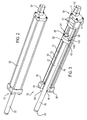
Fig. 2 is a perspective view of a linear actuator useful in the fixture ofFig. 1 . -
Fig. 3 is perspective view similar toFig. 2 , but with part of the actuator's housing cut-away to show internal components. -
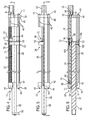
Fig. 4 is a top view of the linear actuator ofFig. 2 , with part of the housing cut-away to show internal components. -
Fig. 5 is a side view of the linear actuator ofFig. 2 , with part of the housing cut-away. -
Fig. 6 is a cross-sectional view taken along the line 6-6 ofFig. 5 . -
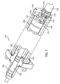
Fig. 7 is a perspective view of another exemplary linear actuator. -
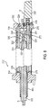
Fig. 8 is a cross-sectional view of the actuator ofFig. 7 . - The invention has application to linear actuators, such as electromechanical linear actuators, for effecting movement of manufacturing components, such as manufacturing workpieces, tools, or tool holders, and thus will be described below chiefly in this context. Such a linear actuator may be suitable for raising, lifting, or otherwise moving or supporting a manufacturing component. The invention can also be useful in other applications where it is desirable to effect movement, such as in construction equipment, gate operation, etc.
- Referring to the drawings,
Fig. 1 shows a manufacturing set up 10, in particular a reconfigurable fixture. The fixture includes a plurality oflinear actuators 12 for raising and/or supporting aworkpiece 14, such as an aircraft wing. Thelinear actuators 12 are secured, such as bolted, to a base surface, such as a work table 16. A portion of the actuators extend vertically therefrom to raise and thereafter maintain a raised height of theworkpiece 14, or more particularly respective regions of theworkpiece 14 for various manufacturing operations, such as cutting or drilling operations. The extension of the linear actuators can be varied to fit the contour of theworkpiece 14 or to determine the contour of theworkpiece 14. As is known, the rod ends of the linear actuators may be equipped with suction devices for holding respective portions of the workpiece surface to the rod ends. -
Figs. 2 to 6 show one of thelinear actuators 12, which includes anactuator housing 20, athrust rod 22 for extending and retracting in relation to theactuator housing 20, adrive screw assembly 24 disposed within theactuator housing 20, and ananti-rotation guide 26 for preventing rotation of the thrust rod relative to thedrive screw assembly 24. Rotational movement of thedrive screw assembly 24 is translated into axial movement of thethrust rod 22 relative to theactuator housing 20. Particularly, thethrust rod 22 is caused to move axially along a longitudinal axis, such as longitudinal axis A of thethrust rod 22 and theactuator housing 20. - As seen in
Figs. 3 to 6 , theactuator housing 20 has a tubular portion orsleeve 32 that extends axially between afirst end 34 and asecond end 36 of the actuator housing. Located at the first andsecond ends proximal end wall 40 and adistal end wall 42, respectively. In the device shown in the drawings, theend walls end caps tubular portion 32. Theend caps tie bars 43 and associatednuts 44, although other suitable attachment means may be used. Thesleeve 32 may be circular in cross-section and the end walls may be generally square in cross-section such that the corners of the end walls project beyond the sleeve. These projecting corners may have formed therein holes through which the ends of the tie bars extend. - The
actuator housing 20 may be made of aluminium, steel, or another suitable material. Theactuator housing 20 may be of a length, width, and height to receive a substantial extent of thethrust rod 22 when thethrust rod 22 is retracted into thehousing interior 32. Thethrust rod 22 extends axially along the longitudinal axis A through anopening 54 in thedistal end wall 42 concentric with the longitudinal axis A for securing thethrust rod 22 from lateral movement and allowing axial movement through it. - The
thrust rod 22 has aproximal end 60 and adistal end 62 that may include a mount for a holding component, such as a suction cup. The length of thethrust rod 22 from theproximal end 60 to thedistal end 62 is illustrated as a solid (i.e., non-hollow) rod. Thethrust rod 22 being solid allows less expensive manufacturing of thethrust rod 22 because manufacturing steps can be avoided. For example, the manufacturing steps to hollow-out a substantial portion of thethrust rod 22, as well as the manufacturing steps to provide a precise and smooth surface inside thethrust rod 22 for a radial bearing to slide within are not necessary. Preferably, theproximal end 62 does not include any opening concentric with thethrust rod 22. More preferably, less than 10% of thethrust rod 22 is hollow. - The
thrust rod 22 may be a cylindrical rod, entirely solid (i.e., non-hollow), substantially solid (i.e., substantially non-hollow), hollow, or of any other suitable shape and cross-section. Further, thethrust rod 22 may be made of steel or another suitable material. - The
distal end 62 of thethrust rod 22 is extendable toward and away from thedistal end 42 of theactuator housing 20. An intermediate portion of thethrust rod 22 is supported during axial movement of thethrust rod 22 to prevent lateral movement by a bearing 64 coaxial with the longitudinal axis A. Thebearing 64 is shown as a bushing disposed in thedistal end wall 42 of theactuator housing 20 and may be any other suitable bearing, such as a radial rod bearing, a slider bearing, or another type of bushing. Thebearing 64 may slidably engage anouter circumference 66 of thethrust rod 22, thus supporting thethrust rod 22 about itsouter circumference 66. Thebearing 64 may seal against theouter circumference 66 to prevent contaminants from entering theactuator housing 20. Otherwise, a seal or wiper may be used to prevent contamination during actuation. Thethrust rod 22 is driven into and out of thehousing 20 by thedrive screw assembly 24. - The
drive screw assembly 24 is rotatably attached to the proximal anddistal end walls drive screw assembly 24 is attached at locations laterally spaced from the longitudinal axis A and thethrust rod 22. Laterally spacing the drive screw assembly allows thethrust rod 22 to be solid (i.e., non-hollow) at theproximal end 60 because the no portion of thedrive screw assembly 24 needs to be located within thethrust rod 22. - As the
drive screw assembly 24 axially drives thethrust rod 22, outward and inward of theactuator housing 20, the drive screw assembly may urge thethrust rod 22 to rotate relative to theactuator housing 20 or thedrive screw assembly 24. Maintaining axial movement allows thethrust rod 22 to extend and retract more easily into a desired position without jamming thethrust rod 22 against bearing 64 or jamming thedrive screw assembly 24. - The
drive screw assembly 24 includes arotatable drive screw 70 disposed in theactuator housing 20 and atranslatable nut member 72 with inner threads that engage with thedrive screw 70. Thedrive screw 70 andtranslatable nut member 72 may be components of any suitable rotational movement to axial movement device, such as a ball screw assembly or of a roller screw assembly. As thedrive screw 70 rotates thetranslatable nut member 72 is driven axially and thereby drives thethrust rod 22 axially. - The
drive screw 70 extends axially along a longitudinal axis B of thedrive screw 70 and includesouter threads 74 between thefirst end 86 and thesecond end 90 of thedrive screw 70. Rotational movement of thedrive screw 70 causes thetranslatable nut member 72 to be translated along the centre longitudinal axis B of thedrive screw 70 relative to the rotational movement of thedrive screw 70. As shown in the drawings, the longitudinal axis A, thethrust rod 22 and theactuator housing 20 may be coincident and the longitudinal axis B is off-set from thethrust rod 22. Thus, rotational movement of thedrive screw 70 may cause thetranslatable nut member 72 to be driven axially along the longitudinal axis A of theactuator housing 20. Thereby, axial movement of thethrust rod 22 coupled to thetranslatable nut member 72 may be effected, the axial movement of thethrust rod 22 also being along the centre axis of the actuator housing. - As shown, the
drive screw 70 extends between the proximal anddistal end walls first end 86 of thedrive screw 70 is disposed within theproximal end wall 40 and asecond end 90 is disposed within thedistal end wall 42. In one construction, a portion of at least one of thefirst end 86 or thesecond end 90 abuts a portion of theactuator housing 20. Thedrive screw 70 is radially outwardly spaced from thethrust rod 22 and the longitudinal axis A relative to theactuator housing 22. Additionally, thethrust rod 22 is radially inwardly spaced from thedrive screw 70 relative to theactuator housing 22 to allow thethrust rod 22 to be concentric with theactuator housing 20 and thedrive screw 70 to be adjacent thetubular portion 32 of theactuator housing 20. Thedrive screw 70 is adjacent to thetubular portion 32 and journalled in theproximal end wall 40 and thedistal end wall 42 by suitable means such as abearing 76 and abearing 78. - The
first end 86 of thedrive screw 70 may be supported against radial and/or axial movement by thebearing 76, such as a radial bearing, a radial screw bearing, an angular contact bearing, or a thrust bearing. Thebearing 76 is disposed within theproximal end wall 40. Alternatively, the end wall may form at least a portion of thebearing 76. In one construction, thefirst end 86 is coupled to a drive shaft of amotor 52. The bearing 76 can be mounted in theproximal end wall 40 or otherwise in theactuator housing 20. Thesecond end 90 of thedrive screw 70 may be supported by thebearing 78. - The
bearing 78 may be coupled, such as rotatably journalled, to an axially extending reduceddiameter portion 88 of thedrive screw 70 at thesecond end 90. Thedrive screw 70 may be rotatably connected to thebearing 78 disposed at thesecond end 86 within thedistal end wall 42 to facilitate holding thedrive screw 70 in tension to counter a buckling force caused by load on thethrust rod 22 exerting force on thetranslatable nut member 72 and buckling of thedrive screw 70. Alternatively, the end wall may form at least a portion of the bearing. Thebearing 78 may be any suitable type of bearing, preferably an angular contact bearing or a thrust bearing, less preferably a radial bearing, bushing, or any other suitable bearing. Use of a bearing type able to support an axial load allows thedrive screw 70 to be put into tension by holding thesecond end 90 of thedrive screw 70 with a bearing that allows thedrive screw 70 to be held. - Holding the
drive screw 70 in tension prevents buckling of thedrive screw 70 and allows better performance and longer life. The tension also allows adrive screw 70 with a smaller diameter to operate at the same load and speed as a larger diameter drive screw without such tension. For example, themotor 52 may attach to thedistal end wall 42, which may be located lower relative to the centre of the earth than theproximal end wall 40 to put thedrive screw 70 in tension. - The
motor 52 drives thedrive screw 70 and may be a rotary motor or any other suitable type of prime mover. Themotor 52 may be coupled to theproximal end wall 40 for securing themotor 52 against rotational movement relative to theactuator housing 20. Theproximal end wall 40 may have afirst opening 50 for allowing coupling of thedrive screw assembly 24 to themotor 52. In one construction, the motor has a drive shaft that is parallel with, but not coaxial with the drive screw. Alternatively, rotational motion of thedrive screw 70 may be provided by any other suitable method at thefirst end 86 opposite thesecond end 90. - At the
second end 90, the reduceddiameter portion 88 extends axially away from thefirst end 86 and is coaxial with the longitudinal axis B. The reduceddiameter portion 88 engages thebearing 78 and allows positioning thedrive screw 70 closer to thethrust rod 22. Positioning thedrive screw 70 closer allows the overall footprint of the linear actuator to be reduced. The reduceddiameter portion 88 may be less than 50% an average diameter of thedrive screw 70 to reduce the footprint of thelinear actuator 12 while still allowing thedrive screw 70 to drive thethrust rod 22 through thetranslatable nut member 72. - The
translatable nut member 72 includes a thrust/guide plate 92 (which may be referred to as a "guide ring" or "piston") and anut 94 with inner threads that engage with thedrive screw 70. Theouter threads 74 of thedrive screw 70 allow threaded engagement with thenut 94. - The
nut 94 includesinner threads 108, shown inFig. 6 , for engaging thedrive screw 70. Theinner threads 108 may be formed of fixed threads or formed by ball bearings. For example, the nut may be a ball screw nut that circulates ball bearings to smoothly translate along thedrive screw 70. The nut may couple thethrust rod 22 to thedrive screw 70, either directly or indirectly, thethrust rod 22 to translate axially in response to rotational movement of thedrive screw 70. Thenut 94 and thethrust rod 22 may be directly coupled, such as fixedly attached via threaded engagement, welding, adhesives, or other suitable method. Alternatively, the thrust/guide plate 92 may have threads for engaging the drive screw. - The thrust/
guide plate 92 is a cylindrical portion with a radially outward facing surface facing theactuator housing 20 and includes anaxially facing surface 96 connected to thenut 94, adrive screw passage 100 parallel to the longitudinal axis A, and ananti-rotation guide passage 102 parallel to the longitudinal axis A. The thrust/guide plate 92 forms one-piece with thethrust rod 22. In one arrangement, the thrust rod is connected to the thrust/guide plate 92 in any suitable manner, such as bolting or welding. In another arrangement, thedrive screw assembly 24 can be slidably coupled to theanti-rotation guide 26 without abutting the actuator housing to prevent rotational movement of the thrust rod. - The
anti-rotation guide 26 prevents rotation of thethrust rod 22 and allows thethrust rod 22 to maintain alignment with the longitudinal axis A and only move axially along the longitudinal axis A. Theanti-rotation guide 26 extends axially between the proximal anddistal end walls anti-rotation guide 26 is connected to the first and second ends 34 and 36 at locations laterally spaced from the longitudinal axis A and diametrically opposite the locations connecting thedrive screw assembly 24. Alternatively, the anti-rotation guide may extend partially between the first and second ends 34 and 36. In one construction, theanti-rotation guide 26 is not diametrically opposite the locations connecting thedrive screw assembly 24 to theactuator housing 20. - The
anti-rotation guide 26 may be laterally spaced from the longitudinal axis A and opposite the locations connecting thedrive screw assembly 24 in any suitable location to prevent rotation of thethrust rod 22 relative to thedrive screw assembly 24. In one construction, an anti-rotation guide and the corresponding anti-rotation guide passage are not present and the drive screw alone prevents rotation of the thrust tube relative to the drive screw assembly. Theproximal end 60 of the thrust rod is supported against radial movement via a portion of the thrust/guide plate 92 abutting an inner wall of theactuator housing 20 and theanti-rotation guide 26 slidably coupling to the thrust/guide plate 92. During use theanti-rotation guide passage 102 slides along theanti-rotation guide 26 while thedrive screw passage 100 slides along or adjacent to thedrive screw 70. - The
drive screw passage 100 is illustrated as generally cylindrical, axially extending, without threading, and laterally off-set from thethrust rod 22 to engage thedrive screw 70. A screw bearing may be disposed within thedrive screw passage 100 to support thedrive screw 70. In one construction, the drive screw passage has inner threading to engage the drive screw. Threading the drive screw passage allows thedrive screw 70 to drive thethrust rod 22 without a nut. Threading thedrive screw passage 100 also allows thedrive screw passage 100 to receive the force otherwise applied to thenut 94 when being driven parallel to theanti-rotation guide passage 102 by thedrive screw 70. - The
anti-rotation guide passage 102 is illustrated as generally cylindrical, axially extending, and laterally off-set from the drive screw passage to slidably connect with theanti-rotation rod 26. Abearing 106 is disposed within theanti-rotation guide passage 102. Thebearing 106 allows a tight slidable connection between theanti-rotation guide passage 102 and theanti-rotation rod 26. In one construction, theanti-rotation guide passage 102 is disposed at a radially outward portion of the thrust/guide plate 92 to engage an axially extending radially inward facing protrusion connected to the actuator housing to prevent rotational movement of thethrust rod 22. In another construction, the anti-rotation guide passage is part of a radially inward facing portion of the actuator housing and engages a radially outward extending protrusion of the thrust/guide plate 92 to prevent rotational movement of thethrust rod 22. - During operation, the
thrust rod 22 extends and retracts to a desired position. Themotor 52 drives thedrive screw 70, which in turn drives thetranslatable nut member 72. Thetranslatable nut member 72 moves axially along thedrive screw 70 to drive thethrust rod 22. Theanti-rotation guide 26 prevents rotation of thetranslatable nut member 72 relative to theanti-rotation guide 26 and allows thetranslatable nut member 72 to move axially along theanti-rotation guide 26 to position thethrust rod 22. Thethrust rod 22 may support a workpiece statically. For example, when thethrust rod 22 is in a desired position, a workpiece may be placed at thedistal end 62 of the thrust rod to support the workpiece in place. - As shown in
Fig. 1 , a plurality oflinear actuators 12 may each include a thrust rod that is positioned based on a relative position of each linear actuator of the plurality oflinear actuators 12. Thus, the thrust rods of each of the plurality of linear actuators may be positioned collectively form the shape of a contour of theworkpiece 14. Alternatively, thethrust rod 22 may be extended or retracted after theworkpiece 14 is placed at thedistal end 62. In one construction, thethrust rod 22 is dynamically loaded. For example, thethrust rod 22 may be moved to re-position an already supported workpiece or additional load may be placed on thethrust rod 22 during manufacturing. In another construction, thethrust rod 22 is used to position components outside of the manufacturing context. For example, thethrust rod 22 may retract or extend a door or wing on a vehicle while the vehicle is in use. -
Figs. 7 and8 show anotherlinear actuator 212 which is substantially the same as thelinear actuator 12 discussed above. The same reference numerals but indexed by 200 respectively are used to denote structures corresponding to similar structures in thelinear actuator 212. In addition, the description of thelinear actuator 12 set out above is equally applicable to thelinear actuator 212 except as noted below. Moreover, aspects of the linear actuators may be substituted for one another or used in conjunction with one another where applicable. -
Figs. 7 and8 show alinear actuator 212 including anactuator housing 220, athrust rod 222 for extending and retracting in relation to theactuator housing 220 and havingouter threads 320, adrive screw assembly 224 disposed within theactuator housing 220, ananti-rotation guide 226 for preventing rotation of the thrust rod relative to thedrive screw assembly 224, and abearing 264 for slidably engagingthrust rod 222. - The
drive screw assembly 224 includes arotatable drive screw 270 disposed in theactuator housing 220 and atranslatable nut member 272 with inner threads that engage with thedrive screw 270. - The
drive screw 270 engages abearing 276 that is held in place by anut 318. Thebearing 276 may be any suitable bearing, such as an angular contact bearing. Thenut 318 engages thedrive screw 270 to axially abut thebearing 276 and prevent axial movement relative to thedrive screw 270. Thenut 318 may be any suitable nut, such as a lock nut. In one construction, an axially facing portion of amotor 252 abuts the bearing 276 to hold thebearing 276 in place. As thedrive screw 270 rotates thetranslatable nut member 272 is driven axially and thereby drives thethrust rod 222 axially. - The
translatable nut member 272 includes a thrust/guide plate 292 (which may be referred to as a "guide ring" or "piston") withinner threads 322 that engage with theouter threads 320 of thethrust rod 222 and anut 294 with inner threads that engage with thedrive screw 270. Theinner threads 322 extend concentrically with theouter threads 320 to prevent axial movement of thethrust rod 222 relative to the thrust/guide plate 292. - The thrust/
guide plate 292 engages with and axially translates with thenut 294. The thrust/guide plate 292 hasinner threads 324 that engage with and are coaxial withouter threads 326 of thenut 294 to prevent the thrust/guide plate 292 from relative axial movement relative to thenut 294. - The thrust/
guide plate 292 further includes abearing 330 coaxial with theanti-rotation guide 226. Thebearing 330 allows the thrust/guide plate 292 to translate axially along theanti-rotation guide 226 and also engages theanti-rotation guide 226 to prevent radial movement of the thrust/guide plate 292 relative to theanti-rotation guide 226. - As best shown in
Fig. 8 , theanti-rotation guide 226 includes afirst engagement portion 332 and asecond engagement portion 334 at opposite ends of theanti-rotation guide 226 for radially fixing theanti-rotation guide 226 to theactuator housing 220. The first andsecond engagement portions anti-rotation guide 226 during retraction or extension, thethrust rod 222 slides along thebearing 264. - Referring again to
Figs. 7 and8 , thebearing 264 extends axially outside of theactuator housing 220. Extending thebearing 264 axially outside allows greater support of thethrust rod 222 to prevent radial bending of thethrust rod 222. Greater than 60% of a length of thebearing 264 extends axially outside of theactuator housing 220. In one construction, 60% or less of thebearing 264 extends axially outside of theactuator housing 220 to allow greater displacement length of thethrust rod 22. Thebearing 264 may be any suitable bearing, such as a bushing, preferably a two-piece bronze bushing. - Although the invention has been shown and described with respect to a certain embodiment or embodiments, it is obvious that equivalent alterations and modifications will occur to others skilled in the art upon the reading and understanding of this specification and the annexed drawings. In particular regard to the various functions performed by the above described elements (components, assemblies, devices, compositions, etc.), the terms (including a reference to a "means") used to describe such elements are intended to correspond, unless otherwise indicated, to any element which performs the specified function of the described element (i.e., that is functionally equivalent), even though not structurally equivalent to the disclosed structure which performs the function in the herein illustrated exemplary embodiment or embodiments of the invention. In addition, while a particular feature of the invention may have been described above with respect to only one or more of several illustrated embodiments, such feature may be combined with one or more other features of the other embodiments, as may be desired and advantageous for any given or particular application.
Claims (15)
- A linear actuator including:a housing,a thrust rod disposed centrally within the housing and having an end portion extending from an end of the housing, the thrust rod having a longitudinal axis,a rotatable drive screw disposed within the housing and having a longitudinal axis parallel to the longitudinal axis of the thrust rod, anda translatable nut member disposed within the housing in threaded engagement with the drive screw and connected to the thrust rod for longitudinal movement therewith, the translatable nut member being driven along the longitudinal axis of the drive screw upon rotation of the drive screw along the longitudinal axis of the drive screw,in which the drive screw is radially outwardly offset from the centrally disposed thrust rod.
- A linear actuator including:a housing having a longitudinal centre axis,a thrust rod disposed within the housing and having an end portion extending from an end of the housing, the thrust rod having a longitudinal axis,a rotatable drive screw disposed within the housing and having a longitudinal axis parallel to and offset from the longitudinal centre axis of the housing, anda translatable nut member disposed within the housing in threaded engagement with the drive screw and connected to the thrust rod for longitudinal movement therewith, the translatable nut member being driven upon rotation of the drive screw along the longitudinal axis of the drive screw.
- A linear actuator including:a housing having a longitudinal centre axis,a thrust rod disposed within the housing and having an end portion extending from an end of the housing, the thrust rod having a longitudinal axis,a rotatable drive screw disposed within the housing and having a longitudinal axis parallel to the longitudinal axis of the thrust rod,a translatable nut member disposed within the housing in threaded engagement with the drive screw and connected to the thrust rod for longitudinal movement therewith, the translatable nut member being driven upon rotation of the drive screw along the longitudinal axis of the drive screw, andan anti-rotation guide extending along a length of the housing parallel to the longitudinal axis of the drive screw, the anti-rotation guide being located at a side of the thrust rod diametrically opposite the drive screw.
- The linear actuator of any one of claims 1 to 3, in which opposite ends of the drive screw are rotatably supported by respective bearings fixed in the housing.
- The linear actuator of any one of claims 1 to 4, further including an anti-rotation guide configured to prevent rotation of the translatable nut member or the thrust rod or each of the translatable nut member and the thrust rod about the longitudinal axis of the drive screw.
- The linear actuator of claim 5, in which the anti-rotation guide includes a rod extending between opposite ends of the housing and on which the translatable nut member slides.
- The linear actuator of claim 5 or claim 6, in which the anti-rotation guide is disposed on a side of the thrust rod diametrically opposite the drive screw.
- The linear actuator of any one of claims 1 to 7, in which the translatable nut member includes a thrust plate to which the thrust rod is attached and a nut attached to the thrust plate.
- The linear actuator of any one of claims 1 to 8, in which the longitudinal axis of thrust rod is concentric with the longitudinal axis of the housing.
- The linear actuator of any one of claims 1 to 9, in which the thrust rod is movable between a fully retracted position and a fully extended position, and in which the extent of the thrust rod that is housed within the housing when in the retracted position of the thrust rod has a solid cross-section.
- The linear actuator of any one of claims 1 to 10, in which there is only a single said thrust rod.
- The linear actuator of any one of claims 1 to 11, further including a motor coupled to the drive screw, preferably with a rotational axis of the motor coaxial with the longitudinal axis of the drive screw.
- The linear actuator of any one of claims 1 to 12, in which the drive screw includes a reduced diameter portion at an end of the drive screw.
- A reconfigurable fixture comprising a base and a plurality of the linear actuators of any one of claims 1 to 13 mounted to the base, preferably with the actuators disposed parallel with respect to one another.
- The reconfigurable fixture of claim 14, in which the thrust rods of the linear actuators are equipped with holding devices such as suction cups for holding the workpiece to the thrust rods.
Applications Claiming Priority (1)
| Application Number | Priority Date | Filing Date | Title |
|---|---|---|---|
| US201361871469P | 2013-08-29 | 2013-08-29 |
Publications (2)
| Publication Number | Publication Date |
|---|---|
| EP2905507A2 true EP2905507A2 (en) | 2015-08-12 |
| EP2905507A3 EP2905507A3 (en) | 2016-03-16 |
Family
ID=51421954
Family Applications (1)
| Application Number | Title | Priority Date | Filing Date |
|---|---|---|---|
| EP14182817.8A Withdrawn EP2905507A3 (en) | 2013-08-29 | 2014-08-29 | Thrust cylinder with offset drive screw |
Country Status (2)
| Country | Link |
|---|---|
| US (1) | US20150059503A1 (en) |
| EP (1) | EP2905507A3 (en) |
Cited By (1)
| Publication number | Priority date | Publication date | Assignee | Title |
|---|---|---|---|---|
| CN107120403A (en) * | 2017-05-15 | 2017-09-01 | 浙江卓求传动科技有限公司 | A kind of Bidirectional slide adjusts self-locking ball screw |
Families Citing this family (6)
| Publication number | Priority date | Publication date | Assignee | Title |
|---|---|---|---|---|
| ITRM20120587A1 (en) * | 2012-11-22 | 2014-05-23 | Umbra Cuscinetti Spa | LINEAR ELECTROMECHANICAL ACTUATOR WITH INTEGRATED ANTI-ROTATION. |
| JP6740090B2 (en) * | 2016-11-11 | 2020-08-12 | 日本電産コパル株式会社 | Screw feeder |
| FR3070062B1 (en) * | 2017-08-09 | 2019-08-23 | Commissariat A L`Energie Atomique Et Aux Energies Alternatives | ANTI-ROTATION WITH CABLES |
| JP7072443B2 (en) * | 2018-05-31 | 2022-05-20 | 日本電産サンキョー株式会社 | Linear drive |
| DE102023204920A1 (en) * | 2023-05-26 | 2024-11-28 | Robert Bosch Gesellschaft mit beschränkter Haftung | Steering gear for a steer-by-wire steering system of a motor vehicle |
| US12358221B1 (en) * | 2024-03-25 | 2025-07-15 | King Saud University | Three-dimensional (3D) printer having a variously configurable printing platform assembly |
Family Cites Families (13)
| Publication number | Priority date | Publication date | Assignee | Title |
|---|---|---|---|---|
| US6435048B1 (en) * | 2001-02-02 | 2002-08-20 | Suspa Incorporated | Multi-leg telescopic linear actuator |
| US20020162410A1 (en) * | 2001-05-03 | 2002-11-07 | Zimmerman Dean A. | Telescopic linear actuator |
| US8806973B2 (en) * | 2009-12-02 | 2014-08-19 | Covidien Lp | Adapters for use between surgical handle assembly and surgical end effector |
| JP4627414B2 (en) * | 2003-12-25 | 2011-02-09 | Thk株式会社 | Actuator and motion guide device |
| US8079578B2 (en) * | 2007-09-05 | 2011-12-20 | Hgs Aerospace, Inc. | Universal holding fixture |
| FR2943394A1 (en) * | 2009-03-23 | 2010-09-24 | Martin Breiter | MECHANISM FOR DRIVING A WORK ORGAN WITH LINEAR RUNS RESPECTIVELY FAST AND SLOW |
| EP2697525A1 (en) * | 2011-04-15 | 2014-02-19 | Ball Screws & Actuators Co. | Linear motion guided screw assembly |
| US8978497B2 (en) * | 2011-05-26 | 2015-03-17 | Tolomatic, Inc. | Linear actuator with anti-rotation mechanism |
| ITTV20110163A1 (en) * | 2011-12-01 | 2013-06-02 | Tendital Di Zanatta F & C Snc | AUTOMATIC DEVICE FOR WASHING CONTINUOUS SURFACES SUCH AS SOLAR / PHOTOVOLTAIC PANELS AND GLASSES IN CONTINUOUS FACADES, EQUIPPED WITH ROTATING BRUSH, MOTOR, CHASSIS AND ADVANCEMENT DEVICE CHARACTERIZED BY THE PRESENCE OF A TORSIO TREE |
| KR101894853B1 (en) * | 2012-05-29 | 2018-10-24 | 엘지이노텍 주식회사 | Swiveling actuator |
| DE102012013979A1 (en) * | 2012-07-13 | 2014-01-16 | Logicdata Electronic & Software Entwicklungs Gmbh | Linaearaktuator and method for producing a linear actuator |
| TWM470445U (en) * | 2012-12-10 | 2014-01-11 | Star Motor Ind Co Ltd J | Linear actuating device |
| GB2512059B (en) * | 2013-03-18 | 2016-08-31 | Rolls Royce Plc | An independently moveable machine tool |
-
2014
- 2014-08-29 US US14/472,662 patent/US20150059503A1/en not_active Abandoned
- 2014-08-29 EP EP14182817.8A patent/EP2905507A3/en not_active Withdrawn
Non-Patent Citations (1)
| Title |
|---|
| None |
Cited By (1)
| Publication number | Priority date | Publication date | Assignee | Title |
|---|---|---|---|---|
| CN107120403A (en) * | 2017-05-15 | 2017-09-01 | 浙江卓求传动科技有限公司 | A kind of Bidirectional slide adjusts self-locking ball screw |
Also Published As
| Publication number | Publication date |
|---|---|
| EP2905507A3 (en) | 2016-03-16 |
| US20150059503A1 (en) | 2015-03-05 |
Similar Documents
| Publication | Publication Date | Title |
|---|---|---|
| US20150059503A1 (en) | Thrust cylinder with offset drive screw | |
| US8601889B2 (en) | Telescoping dual-spindle drive | |
| US8978497B2 (en) | Linear actuator with anti-rotation mechanism | |
| JP6576464B2 (en) | 4-stage telescope actuator with screw drive mechanism | |
| DE4104759A1 (en) | COMPACT, ELECTRICALLY DRIVEN LINEAR ACTUATOR | |
| US8635922B2 (en) | Height-adjustable actuation device | |
| US20140157921A1 (en) | Linear actuator | |
| US20100320714A1 (en) | Retractable vehicle step | |
| US20020104395A1 (en) | Multi-leg telescopic linear actuator | |
| CN105529866B (en) | High-thrust linear electric push rod | |
| US8922451B2 (en) | Lockdown mechanism for an electric drive screw telescoping mast system | |
| CN207206140U (en) | Brake drum honing fixture and honing system | |
| CN110224544B (en) | Double-head driving push rod, lifting leg and lifting table | |
| US3389413A (en) | Single spindle tap unit | |
| US9797489B2 (en) | Actuator thrust rod and method of assembly | |
| US20170328111A1 (en) | Window lift mechanism | |
| CN103358274B (en) | Dedicated tool for oil seal assembly | |
| KR101939319B1 (en) | Linear actuator | |
| CN113679287B (en) | Speed-multiplying motion telescopic mechanical arm and cleaning robot | |
| US9751179B2 (en) | Lathe positioning apparatus | |
| EP4488573B1 (en) | Light signalling device for the bow of a ship | |
| CN117321329A (en) | Telescopic column with stabilizing device | |
| US10717632B2 (en) | Bolting device | |
| CN209288628U (en) | Pneumatic modified gear | |
| CN119801349B (en) | A door hinge, a door, and a vehicle |
Legal Events
| Date | Code | Title | Description |
|---|---|---|---|
| PUAI | Public reference made under article 153(3) epc to a published international application that has entered the european phase |
Free format text: ORIGINAL CODE: 0009012 |
|
| AK | Designated contracting states |
Kind code of ref document: A2 Designated state(s): AL AT BE BG CH CY CZ DE DK EE ES FI FR GB GR HR HU IE IS IT LI LT LU LV MC MK MT NL NO PL PT RO RS SE SI SK SM TR |
|
| AX | Request for extension of the european patent |
Extension state: BA ME |
|
| PUAL | Search report despatched |
Free format text: ORIGINAL CODE: 0009013 |
|
| AK | Designated contracting states |
Kind code of ref document: A3 Designated state(s): AL AT BE BG CH CY CZ DE DK EE ES FI FR GB GR HR HU IE IS IT LI LT LU LV MC MK MT NL NO PL PT RO RS SE SI SK SM TR |
|
| AX | Request for extension of the european patent |
Extension state: BA ME |
|
| RIC1 | Information provided on ipc code assigned before grant |
Ipc: F16H 25/20 20060101AFI20160208BHEP Ipc: B23Q 1/03 20060101ALI20160208BHEP |
|
| STAA | Information on the status of an ep patent application or granted ep patent |
Free format text: STATUS: THE APPLICATION IS DEEMED TO BE WITHDRAWN |
|
| 18D | Application deemed to be withdrawn |
Effective date: 20160917 |