EP2905473A1 - A fan casing for a gas turbine engine - Google Patents
A fan casing for a gas turbine engine Download PDFInfo
- Publication number
- EP2905473A1 EP2905473A1 EP15150885.0A EP15150885A EP2905473A1 EP 2905473 A1 EP2905473 A1 EP 2905473A1 EP 15150885 A EP15150885 A EP 15150885A EP 2905473 A1 EP2905473 A1 EP 2905473A1
- Authority
- EP
- European Patent Office
- Prior art keywords
- casing
- core
- projection
- casing according
- fire resistant
- Prior art date
- Legal status (The legal status is an assumption and is not a legal conclusion. Google has not performed a legal analysis and makes no representation as to the accuracy of the status listed.)
- Granted
Links
- 230000003014 reinforcing effect Effects 0.000 claims abstract description 21
- 239000002131 composite material Substances 0.000 claims abstract description 18
- 230000009970 fire resistant effect Effects 0.000 claims abstract description 15
- 239000000835 fiber Substances 0.000 claims abstract description 8
- 239000004033 plastic Substances 0.000 claims abstract description 8
- 239000011153 ceramic matrix composite Substances 0.000 claims abstract description 6
- 239000000463 material Substances 0.000 claims abstract description 5
- RTAQQCXQSZGOHL-UHFFFAOYSA-N Titanium Chemical group [Ti] RTAQQCXQSZGOHL-UHFFFAOYSA-N 0.000 claims description 12
- XQUPVDVFXZDTLT-UHFFFAOYSA-N 1-[4-[[4-(2,5-dioxopyrrol-1-yl)phenyl]methyl]phenyl]pyrrole-2,5-dione Chemical compound O=C1C=CC(=O)N1C(C=C1)=CC=C1CC1=CC=C(N2C(C=CC2=O)=O)C=C1 XQUPVDVFXZDTLT-UHFFFAOYSA-N 0.000 claims description 11
- OKTJSMMVPCPJKN-UHFFFAOYSA-N Carbon Chemical compound [C] OKTJSMMVPCPJKN-UHFFFAOYSA-N 0.000 claims description 11
- 229910052799 carbon Inorganic materials 0.000 claims description 11
- 229920003192 poly(bis maleimide) Polymers 0.000 claims description 11
- 125000006850 spacer group Chemical group 0.000 claims description 8
- 239000011159 matrix material Substances 0.000 claims description 4
- ZOXJGFHDIHLPTG-UHFFFAOYSA-N Boron Chemical compound [B] ZOXJGFHDIHLPTG-UHFFFAOYSA-N 0.000 claims description 2
- 239000004760 aramid Substances 0.000 claims description 2
- 229920003235 aromatic polyamide Polymers 0.000 claims description 2
- 229910052796 boron Inorganic materials 0.000 claims description 2
- 239000000919 ceramic Substances 0.000 claims description 2
- 239000003822 epoxy resin Substances 0.000 claims description 2
- 239000011521 glass Substances 0.000 claims description 2
- 229920000647 polyepoxide Polymers 0.000 claims description 2
- 229920001721 polyimide Polymers 0.000 claims description 2
- 239000009719 polyimide resin Substances 0.000 claims description 2
- 239000007769 metal material Substances 0.000 abstract 1
- 229920005989 resin Polymers 0.000 description 16
- 239000011347 resin Substances 0.000 description 16
- 239000010936 titanium Substances 0.000 description 7
- 229910052719 titanium Inorganic materials 0.000 description 7
- 229910052751 metal Inorganic materials 0.000 description 6
- 239000002184 metal Substances 0.000 description 6
- 238000002485 combustion reaction Methods 0.000 description 3
- 230000013011 mating Effects 0.000 description 3
- 238000000034 method Methods 0.000 description 3
- 230000001141 propulsive effect Effects 0.000 description 3
- HBMJWWWQQXIZIP-UHFFFAOYSA-N silicon carbide Chemical compound [Si+]#[C-] HBMJWWWQQXIZIP-UHFFFAOYSA-N 0.000 description 3
- 229910010271 silicon carbide Inorganic materials 0.000 description 3
- 238000009745 resin transfer moulding Methods 0.000 description 2
- 239000007787 solid Substances 0.000 description 2
- 229910001069 Ti alloy Inorganic materials 0.000 description 1
- 229910017052 cobalt Inorganic materials 0.000 description 1
- 239000010941 cobalt Substances 0.000 description 1
- GUTLYIVDDKVIGB-UHFFFAOYSA-N cobalt atom Chemical compound [Co] GUTLYIVDDKVIGB-UHFFFAOYSA-N 0.000 description 1
- ZGDWHDKHJKZZIQ-UHFFFAOYSA-N cobalt nickel Chemical compound [Co].[Ni].[Ni].[Ni] ZGDWHDKHJKZZIQ-UHFFFAOYSA-N 0.000 description 1
- 239000000805 composite resin Substances 0.000 description 1
- 230000006835 compression Effects 0.000 description 1
- 238000007906 compression Methods 0.000 description 1
- 230000008021 deposition Effects 0.000 description 1
- 238000009792 diffusion process Methods 0.000 description 1
- 239000012530 fluid Substances 0.000 description 1
- 239000000446 fuel Substances 0.000 description 1
- 239000000155 melt Substances 0.000 description 1
- 239000000203 mixture Substances 0.000 description 1
- 238000012986 modification Methods 0.000 description 1
- 230000004048 modification Effects 0.000 description 1
- 230000002035 prolonged effect Effects 0.000 description 1
- 239000007921 spray Substances 0.000 description 1
- 230000002459 sustained effect Effects 0.000 description 1
- 238000001721 transfer moulding Methods 0.000 description 1
Images



Classifications
-
- F—MECHANICAL ENGINEERING; LIGHTING; HEATING; WEAPONS; BLASTING
- F01—MACHINES OR ENGINES IN GENERAL; ENGINE PLANTS IN GENERAL; STEAM ENGINES
- F01D—NON-POSITIVE DISPLACEMENT MACHINES OR ENGINES, e.g. STEAM TURBINES
- F01D25/00—Component parts, details, or accessories, not provided for in, or of interest apart from, other groups
- F01D25/08—Cooling; Heating; Heat-insulation
- F01D25/14—Casings modified therefor
- F01D25/145—Thermally insulated casings
-
- F—MECHANICAL ENGINEERING; LIGHTING; HEATING; WEAPONS; BLASTING
- F01—MACHINES OR ENGINES IN GENERAL; ENGINE PLANTS IN GENERAL; STEAM ENGINES
- F01D—NON-POSITIVE DISPLACEMENT MACHINES OR ENGINES, e.g. STEAM TURBINES
- F01D25/00—Component parts, details, or accessories, not provided for in, or of interest apart from, other groups
- F01D25/005—Selecting particular materials
-
- F—MECHANICAL ENGINEERING; LIGHTING; HEATING; WEAPONS; BLASTING
- F01—MACHINES OR ENGINES IN GENERAL; ENGINE PLANTS IN GENERAL; STEAM ENGINES
- F01D—NON-POSITIVE DISPLACEMENT MACHINES OR ENGINES, e.g. STEAM TURBINES
- F01D25/00—Component parts, details, or accessories, not provided for in, or of interest apart from, other groups
- F01D25/24—Casings; Casing parts, e.g. diaphragms, casing fastenings
- F01D25/243—Flange connections; Bolting arrangements
-
- F—MECHANICAL ENGINEERING; LIGHTING; HEATING; WEAPONS; BLASTING
- F04—POSITIVE - DISPLACEMENT MACHINES FOR LIQUIDS; PUMPS FOR LIQUIDS OR ELASTIC FLUIDS
- F04D—NON-POSITIVE-DISPLACEMENT PUMPS
- F04D29/00—Details, component parts, or accessories
- F04D29/02—Selection of particular materials
- F04D29/023—Selection of particular materials especially adapted for elastic fluid pumps
-
- F—MECHANICAL ENGINEERING; LIGHTING; HEATING; WEAPONS; BLASTING
- F04—POSITIVE - DISPLACEMENT MACHINES FOR LIQUIDS; PUMPS FOR LIQUIDS OR ELASTIC FLUIDS
- F04D—NON-POSITIVE-DISPLACEMENT PUMPS
- F04D29/00—Details, component parts, or accessories
- F04D29/40—Casings; Connections of working fluid
- F04D29/52—Casings; Connections of working fluid for axial pumps
- F04D29/54—Fluid-guiding means, e.g. diffusers
- F04D29/541—Specially adapted for elastic fluid pumps
- F04D29/545—Ducts
-
- F—MECHANICAL ENGINEERING; LIGHTING; HEATING; WEAPONS; BLASTING
- F05—INDEXING SCHEMES RELATING TO ENGINES OR PUMPS IN VARIOUS SUBCLASSES OF CLASSES F01-F04
- F05D—INDEXING SCHEME FOR ASPECTS RELATING TO NON-POSITIVE-DISPLACEMENT MACHINES OR ENGINES, GAS-TURBINES OR JET-PROPULSION PLANTS
- F05D2300/00—Materials; Properties thereof
- F05D2300/10—Metals, alloys or intermetallic compounds
- F05D2300/17—Alloys
- F05D2300/174—Titanium alloys, e.g. TiAl
-
- F—MECHANICAL ENGINEERING; LIGHTING; HEATING; WEAPONS; BLASTING
- F05—INDEXING SCHEMES RELATING TO ENGINES OR PUMPS IN VARIOUS SUBCLASSES OF CLASSES F01-F04
- F05D—INDEXING SCHEME FOR ASPECTS RELATING TO NON-POSITIVE-DISPLACEMENT MACHINES OR ENGINES, GAS-TURBINES OR JET-PROPULSION PLANTS
- F05D2300/00—Materials; Properties thereof
- F05D2300/20—Oxide or non-oxide ceramics
- F05D2300/21—Oxide ceramics
-
- F—MECHANICAL ENGINEERING; LIGHTING; HEATING; WEAPONS; BLASTING
- F05—INDEXING SCHEMES RELATING TO ENGINES OR PUMPS IN VARIOUS SUBCLASSES OF CLASSES F01-F04
- F05D—INDEXING SCHEME FOR ASPECTS RELATING TO NON-POSITIVE-DISPLACEMENT MACHINES OR ENGINES, GAS-TURBINES OR JET-PROPULSION PLANTS
- F05D2300/00—Materials; Properties thereof
- F05D2300/40—Organic materials
- F05D2300/43—Synthetic polymers, e.g. plastics; Rubber
-
- F—MECHANICAL ENGINEERING; LIGHTING; HEATING; WEAPONS; BLASTING
- F05—INDEXING SCHEMES RELATING TO ENGINES OR PUMPS IN VARIOUS SUBCLASSES OF CLASSES F01-F04
- F05D—INDEXING SCHEME FOR ASPECTS RELATING TO NON-POSITIVE-DISPLACEMENT MACHINES OR ENGINES, GAS-TURBINES OR JET-PROPULSION PLANTS
- F05D2300/00—Materials; Properties thereof
- F05D2300/50—Intrinsic material properties or characteristics
- F05D2300/502—Thermal properties
-
- F—MECHANICAL ENGINEERING; LIGHTING; HEATING; WEAPONS; BLASTING
- F05—INDEXING SCHEMES RELATING TO ENGINES OR PUMPS IN VARIOUS SUBCLASSES OF CLASSES F01-F04
- F05D—INDEXING SCHEME FOR ASPECTS RELATING TO NON-POSITIVE-DISPLACEMENT MACHINES OR ENGINES, GAS-TURBINES OR JET-PROPULSION PLANTS
- F05D2300/00—Materials; Properties thereof
- F05D2300/60—Properties or characteristics given to material by treatment or manufacturing
- F05D2300/603—Composites; e.g. fibre-reinforced
-
- F—MECHANICAL ENGINEERING; LIGHTING; HEATING; WEAPONS; BLASTING
- F05—INDEXING SCHEMES RELATING TO ENGINES OR PUMPS IN VARIOUS SUBCLASSES OF CLASSES F01-F04
- F05D—INDEXING SCHEME FOR ASPECTS RELATING TO NON-POSITIVE-DISPLACEMENT MACHINES OR ENGINES, GAS-TURBINES OR JET-PROPULSION PLANTS
- F05D2300/00—Materials; Properties thereof
- F05D2300/70—Treatment or modification of materials
- F05D2300/702—Reinforcement
Definitions
- the present invention relates to a fan casing for a gas turbine engine.
- the present invention relates to a fire resistant fan casing having a projection such as a reinforcing rib or a mounting pad.
- Gas turbine engines are typically surrounded by a fan casing which may be formed of a composite material comprising carbon fibres and a plastic material, e.g. bismaleimide (BMI) resin.
- a fan casing which may be formed of a composite material comprising carbon fibres and a plastic material, e.g. bismaleimide (BMI) resin.
- BMI bismaleimide
- an annular reinforcing rib is provided.
- fan casings can be required to be fire resistant and it has been found that fan casings having a reinforcing rib formed of a carbon fibre/BMI resin composite tend to fail the industry requirements for fire resistance - it has been observed that significant flame is sustained by the composite reinforcing rib after removal of the heat source and this is unacceptable. It is thought that this is a result of the thickness of the reinforcing rib leading to a pool of resin that is too great to be burned-off during the fire resistance tests.
- the annular reinforcing rib has a thickness that varies circumferentially. Attempts to replace the thicker portions of the composite reinforcing rib with metal (e.g. titanium) portions bolted to the composite reinforcing rib has been found to lead to an undesirable increase in fan casing weight, cost and part count.
- metal e.g. titanium
- the inventors have found that reducing the thickness of the thicker portions of the composite reinforcing rib and reinforcing them with laterally opposed metal (e.g. titanium) plates bolted to one another through the rib is unsuccessful - it is thought that the metal plates shield the composite reinforcing rib from the flame but act as a heat sink to sustain resin ignition as it melts and moves to the surface of the reinforcing rib through the bolt holes.
- laterally opposed metal e.g. titanium
- Mounting pads are also provided on fan casings for mounting/supporting accessories from the fan casing. These pads (also known as “pad up patches”) typically comprise thickened portions of the fan casing and, again, these thickened portions can result in a reservoir of resin that is too great to be burned off during the fire resistance test.
- the present invention provides a casing having a projection, wherein the projection comprises at least one shell portion formed of fibre/plastic composite material encasing a core of fire resistant material.
- the structural strength of the projection can be maintained but the pool of flammable resin is reduced thus avoiding continued burn of the projection after removal of the heat source during tests i.e. thus improving fire resistance of the casing.
- the projection is a reinforcing rib.
- the projection is a mounting pad.
- the casing e.g. a casing for a gas turbine engine
- the casing comprises an annular (e.g. cylindrical or conical) casing with the projection extending radially from and at least partly circumscribing the annular casing.
- the projection may be an annular projection circumscribing the annular casing.
- the projection may comprise a plurality of shell portions each containing a respective core (e.g. annularly spaced shell portions each circumscribing a portion of the annular casing). In some embodiments, the projection may comprise a single shell portion circumscribing the annular casing.
- the core is selected such that it maintains its structural integrity at high temperatures, does not thermally decompose to generate flammable fluids and has a similar coefficient of thermal expansion to the shell portion over normal operating temperatures (to avoid excessive interface stresses). In some embodiments, it is selected to contribute to the stiffening function of the rib. In some embodiments, it is selected to be lightweight.
- the fire resistant core may be a metallic (e.g. titanium or a titanium alloy) core, a metallic matrix composite (MMC) core, a ceramic core or a ceramic matrix composite (CMC) core. It may comprise fibres e.g. carbon fibres or silicon carbide fibres.
- MMC metallic matrix composite
- CMC ceramic matrix composite
- the core helps strengthen and/or stiffen the projection without the need for interface fasteners since the core is constrained/enclosed within the respective shell portion.
- a suitable metallic matrix core comprises fibres (e.g. silicon carbide fibres) coated in metal (e.g. titanium, cobalt or cobalt-nickel) by spray or vapour deposition subsequently combined using known solid state joining methods such as diffusion bonding, heat and/or pressure to form the core.
- a suitable ceramic matrix composite (CMC) core may comprise carbon fibres in a silicon carbide matrix.
- The/each core can have any cross-sectional profile but may have a circular, rectangular, square, wedge-shaped or T-shaped cross-sectional profile.
- the cross-sectional area of the core may vary circumferentially.
- the or each core is solid. In some embodiments it may be a meshed, ribbed or foamed structure and/or it may contain recesses and/or channels/grooves.
- the core may be formed of a foamed metal e.g. foamed titanium. The core may be machined to form surface grooves, channels or recesses. A meshed, ribbed or foamed structure reduces weight whilst recesses/channels/grooves help intimate binding to the shell portion e.g. using resin transfer molding.
- the fibre/plastic composite material forming the shell portion may comprise fibres of carbon, glass, aramid or boron.
- the fibres may form a laminated or woven fibrous network.
- the fibre/plastic composite material may comprise a bismaleimide (BMI), epoxy or polyimide resin.
- the thickness of the shell portion may be around or less than 6mm such that rapid burn-off of the resin may occur.
- the fibrous network forming the shell portion may be formed around the fire resistant core and placed in a mould.
- resin is introduced into the mould under high pressure and the resin infuses and keys with the fibrous network and with the fire resistant core (especially if the core is meshed, ribbed or foamed or has surface recesses/channels/grooves).
- the casing e.g. annular casing
- the casing may also be formed of the fibre/plastic composite material.
- the projection may be integral with the casing e.g. by integrating the fibrous network of the projection with the fibrous network of the casing.
- the projection e.g., the reinforcing rib comprises a spacer portion spacing the shell portion from the casing.
- the spacer portion allows for connection (e.g. via a bolt) to an adjacent casing or mating ring where the rib is located at an end of the casing adjacent a flange connection of an adjacent casing or mating ring.
- the present invention provides a gas turbine engine having a casing according to the first aspect.
- a ducted fan gas turbine engine incorporating the invention is generally indicated at 10 and has a principal and rotational axis X-X.
- the engine comprises, in axial flow series, an air intake 11, a propulsive fan 12, an intermediate pressure compressor 13, a high-pressure compressor 14, combustion equipment 15, a high-pressure turbine 16, an intermediate pressure turbine 17, a low-pressure turbine 18 and a core engine exhaust nozzle 19.
- a nacelle 21 generally surrounds the engine 10 and defines the intake 11, a bypass duct 22 and a bypass exhaust nozzle 23.
- air entering the intake 11 is accelerated by the fan 12 to produce two air flows: a first air flow A into the intermediate pressure compressor 13 and a second air flow B which passes through the bypass duct 22 to provide propulsive thrust.
- the intermediate pressure compressor 13 compresses the air flow A directed into it before delivering that air to the high pressure compressor 14 where further compression takes place.
- the compressed air exhausted from the high-pressure compressor 14 is directed into the combustion equipment 15 where it is mixed with fuel and the mixture combusted.
- the resultant hot combustion products then expand through, and thereby drive the high, intermediate and low-pressure turbines 16, 17, 18 before being exhausted through the nozzle 19 to provide additional propulsive thrust.
- the high, intermediate and low-pressure turbines respectively drive the high and intermediate pressure compressors 14, 13 and the fan 12 by suitable interconnecting shafts.
- the engine is surrounded by an annular fan case 24 formed of carbon fibre-reinforced bismaleimide resin.
- a projection 25 is provided extending radially outwardly from the annular fan case 24.
- FIG. 2 to 4 show an annular reinforcing rib which circumscribes the fan casing 24 whilst Figures 5 and 5b show a mounting pad.
- the reinforcing rib 25' comprises a shell portion 26.
- the shell portion 26 is spaced from the fan casing 24 by a spacer portion 27.
- the spacer portion 27 is connected to an adjacent titanium mating ring 28 through a bolt 30.
- this embodiment can be used to mount an accessory 31 via an axial bolt 30 through the core 29 (as shown in Figure 4b ).
- the fan case 24 and shell portion 26 are all formed of carbon fibre-reinforced bismaleimide resin in this example.
- the carbon fibres form a woven fibrous network infused with the resin.
- the fibrous network of the fan case 24 and shell portion 26 (and spacer portion 27 when present) are integrated such that the rib 25' is integral with the fan case 24.
- FIG. 5 and 5b shows an embodiment having a mounting pad 25" onto which accessories can be bolted to secure them to the fan casing 24.
- the mounting pad 25" has a shell portion 26 which is integral with the fan casing 24.
- the fan casing 24 and shell portion are formed of carbon fibre-reinforced bismaleimide resin.
- the shell portion 26 encases a core 29 formed of titanium metal.
- the surface of the titanium core is machined to form grooves to help intimate bonding between the core and the shell portion.
- the core 29 has a square cross-sectional profile
- the core 29 has a rectangular cross-sectional profile (with the major axis of the rectangular core axially aligned with the casing)
- the core 29 has a T-shaped cross-sectional profile.
- the embodiment shown in Figure 5b has a wedge-shaped cross-sectional profile.
- a wedge-shaped core is useful for maintaining a cylindrical mounting surface on a conical annular casing.
- the radial cross-sectional profile of the core 29 can vary circumferentially for the mounting pad according to the fifth and sixth embodiments.
- the fibrous network of carbon fibres of the shell portion is formed around the grooved titanium core and placed in a mould.
- bismaleimide resin is introduced into the mould under high pressure and the resin infuses and keys with the fibrous network and with grooves on the titanium core.
- the reinforcing rib 25' comprises a plurality of shell portions/cores circumferentially spaced around the annular rib 25', each shell portion/core circumscribing a portion of the annular casing 24.
- the titanium core maintains the structural strength of the reinforcing projection/mounting pad without the need for a large thickness of composite material which leads to prolonged burning during fire resistant tests.
- the thickness of the composite material in the shell portion is typically less than 6mm such that rapid burn-off of the resin may occur.
Landscapes
- Engineering & Computer Science (AREA)
- Mechanical Engineering (AREA)
- General Engineering & Computer Science (AREA)
- Chemical & Material Sciences (AREA)
- Materials Engineering (AREA)
- Structures Of Non-Positive Displacement Pumps (AREA)
Abstract
Description
- The present invention relates to a fan casing for a gas turbine engine. In particular, the present invention relates to a fire resistant fan casing having a projection such as a reinforcing rib or a mounting pad.
- Gas turbine engines are typically surrounded by a fan casing which may be formed of a composite material comprising carbon fibres and a plastic material, e.g. bismaleimide (BMI) resin. To provide structural rigidity to the fan casing, an annular reinforcing rib is provided.
- Such fan casings can be required to be fire resistant and it has been found that fan casings having a reinforcing rib formed of a carbon fibre/BMI resin composite tend to fail the industry requirements for fire resistance - it has been observed that significant flame is sustained by the composite reinforcing rib after removal of the heat source and this is unacceptable. It is thought that this is a result of the thickness of the reinforcing rib leading to a pool of resin that is too great to be burned-off during the fire resistance tests.
- The annular reinforcing rib has a thickness that varies circumferentially. Attempts to replace the thicker portions of the composite reinforcing rib with metal (e.g. titanium) portions bolted to the composite reinforcing rib has been found to lead to an undesirable increase in fan casing weight, cost and part count.
- The inventors have found that reducing the thickness of the thicker portions of the composite reinforcing rib and reinforcing them with laterally opposed metal (e.g. titanium) plates bolted to one another through the rib is unsuccessful - it is thought that the metal plates shield the composite reinforcing rib from the flame but act as a heat sink to sustain resin ignition as it melts and moves to the surface of the reinforcing rib through the bolt holes.
- Mounting pads are also provided on fan casings for mounting/supporting accessories from the fan casing. These pads (also known as "pad up patches") typically comprise thickened portions of the fan casing and, again, these thickened portions can result in a reservoir of resin that is too great to be burned off during the fire resistance test.
- There is the need to provide a fan casing having a projection which meets the industry standards for fire resistance but which also has an acceptable weight and cost and is ideally integral to the fan case for a low part count.
- In a first aspect, the present invention provides a casing having a projection, wherein the projection comprises at least one shell portion formed of fibre/plastic composite material encasing a core of fire resistant material.
- By replacing the thickened portions of the projection with a composite shell portion containing a fire resistant core, the structural strength of the projection can be maintained but the pool of flammable resin is reduced thus avoiding continued burn of the projection after removal of the heat source during tests i.e. thus improving fire resistance of the casing.
- Optional features of the invention will now be set out. These are applicable singly or in any combination with any aspect of the invention.
- In some embodiments, the projection is a reinforcing rib.
- In some embodiments, the projection is a mounting pad.
- In some embodiments, the casing (e.g. a casing for a gas turbine engine) comprises an annular (e.g. cylindrical or conical) casing with the projection extending radially from and at least partly circumscribing the annular casing. The projection may be an annular projection circumscribing the annular casing.
- In some embodiments, the projection may comprise a plurality of shell portions each containing a respective core (e.g. annularly spaced shell portions each circumscribing a portion of the annular casing). In some embodiments, the projection may comprise a single shell portion circumscribing the annular casing.
- The core is selected such that it maintains its structural integrity at high temperatures, does not thermally decompose to generate flammable fluids and has a similar coefficient of thermal expansion to the shell portion over normal operating temperatures (to avoid excessive interface stresses). In some embodiments, it is selected to contribute to the stiffening function of the rib. In some embodiments, it is selected to be lightweight.
- The fire resistant core may be a metallic (e.g. titanium or a titanium alloy) core, a metallic matrix composite (MMC) core, a ceramic core or a ceramic matrix composite (CMC) core. It may comprise fibres e.g. carbon fibres or silicon carbide fibres. The core helps strengthen and/or stiffen the projection without the need for interface fasteners since the core is constrained/enclosed within the respective shell portion.
- A suitable metallic matrix core comprises fibres (e.g. silicon carbide fibres) coated in metal (e.g. titanium, cobalt or cobalt-nickel) by spray or vapour deposition subsequently combined using known solid state joining methods such as diffusion bonding, heat and/or pressure to form the core. A suitable ceramic matrix composite (CMC) core may comprise carbon fibres in a silicon carbide matrix.
- The/each core can have any cross-sectional profile but may have a circular, rectangular, square, wedge-shaped or T-shaped cross-sectional profile. The cross-sectional area of the core may vary circumferentially.
- In some embodiments, the or each core is solid. In some embodiments it may be a meshed, ribbed or foamed structure and/or it may contain recesses and/or channels/grooves. For example, the core may be formed of a foamed metal e.g. foamed titanium. The core may be machined to form surface grooves, channels or recesses. A meshed, ribbed or foamed structure reduces weight whilst recesses/channels/grooves help intimate binding to the shell portion e.g. using resin transfer molding.
- The fibre/plastic composite material forming the shell portion may comprise fibres of carbon, glass, aramid or boron. The fibres may form a laminated or woven fibrous network. The fibre/plastic composite material may comprise a bismaleimide (BMI), epoxy or polyimide resin.
- The thickness of the shell portion may be around or less than 6mm such that rapid burn-off of the resin may occur.
- To form the projection, the fibrous network forming the shell portion may be formed around the fire resistant core and placed in a mould. Using the known resin transfer moulding (RTM) process, resin is introduced into the mould under high pressure and the resin infuses and keys with the fibrous network and with the fire resistant core (especially if the core is meshed, ribbed or foamed or has surface recesses/channels/grooves).
- The casing (e.g. annular casing) may also be formed of the fibre/plastic composite material.
- In some embodiments, the projection may be integral with the casing e.g. by integrating the fibrous network of the projection with the fibrous network of the casing.
- In some embodiments the projection e.g., the reinforcing rib comprises a spacer portion spacing the shell portion from the casing. The spacer portion allows for connection (e.g. via a bolt) to an adjacent casing or mating ring where the rib is located at an end of the casing adjacent a flange connection of an adjacent casing or mating ring.
- In a second aspect, the present invention provides a gas turbine engine having a casing according to the first aspect.
- Embodiments of the invention will now be described by way of example with reference to the accompanying drawings in which:
-
Figure 1 shows a cross section through a ducted fan gas turbine engine incorporating the invention; -
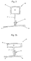
Figure 2 shows an axial cross section through a first embodiment of the invention; -
Figure 2b shows an axial cross section through a second embodiment of the invention; -
Figure 3 shows an axial cross section through a third embodiment of the present invention; -
Figures 4 and 4b show axial cross sections through a fourth embodiment of the invention; -
Figure 5 shows an axial cross section through a fifth embodiment of the present invention; -
Figure 5b shows an axial cross-section through a sixth embodiment of the present invention; and -
Figure 5c shows a radial cross-section through the fifth and sixth embodiments. - With reference to
Figure 1 , a ducted fan gas turbine engine incorporating the invention is generally indicated at 10 and has a principal and rotational axis X-X. The engine comprises, in axial flow series, an air intake 11, apropulsive fan 12, anintermediate pressure compressor 13, a high-pressure compressor 14,combustion equipment 15, a high-pressure turbine 16, anintermediate pressure turbine 17, a low-pressure turbine 18 and a coreengine exhaust nozzle 19. Anacelle 21 generally surrounds theengine 10 and defines the intake 11, abypass duct 22 and abypass exhaust nozzle 23. - During operation, air entering the intake 11 is accelerated by the
fan 12 to produce two air flows: a first air flow A into theintermediate pressure compressor 13 and a second air flow B which passes through thebypass duct 22 to provide propulsive thrust. Theintermediate pressure compressor 13 compresses the air flow A directed into it before delivering that air to thehigh pressure compressor 14 where further compression takes place. - The compressed air exhausted from the high-
pressure compressor 14 is directed into thecombustion equipment 15 where it is mixed with fuel and the mixture combusted. The resultant hot combustion products then expand through, and thereby drive the high, intermediate and low-pressure turbines nozzle 19 to provide additional propulsive thrust. The high, intermediate and low-pressure turbines respectively drive the high andintermediate pressure compressors fan 12 by suitable interconnecting shafts. - The engine is surrounded by an
annular fan case 24 formed of carbon fibre-reinforced bismaleimide resin. Aprojection 25 is provided extending radially outwardly from theannular fan case 24. - Further detail of the
annular projection 25 is shown in the remaining Figures.Figures 2 to 4 show an annular reinforcing rib which circumscribes thefan casing 24 whilstFigures 5 and 5b show a mounting pad. - As shown in
Figures 2 to 4 , the reinforcing rib 25' comprises ashell portion 26. In the embodiments, shown inFigures 2, 2b and3 , theshell portion 26 is spaced from thefan casing 24 by aspacer portion 27. Thespacer portion 27 is connected to an adjacenttitanium mating ring 28 through abolt 30. - In the embodiment shown in
Figure 4 , there is no spacer portion and theshell portion 26 extends to thefan casing 24. In addition to functioning as a reinforcing rib, this embodiment can be used to mount anaccessory 31 via anaxial bolt 30 through the core 29 (as shown inFigure 4b ). - The
fan case 24 and shell portion 26 (andspacer portion 27 when present) are all formed of carbon fibre-reinforced bismaleimide resin in this example. The carbon fibres form a woven fibrous network infused with the resin. The fibrous network of thefan case 24 and shell portion 26 (andspacer portion 27 when present) are integrated such that the rib 25' is integral with thefan case 24. -
Figures 5 and 5b shows an embodiment having a mountingpad 25" onto which accessories can be bolted to secure them to thefan casing 24. The mountingpad 25" has ashell portion 26 which is integral with thefan casing 24. In this example, thefan casing 24 and shell portion are formed of carbon fibre-reinforced bismaleimide resin. - In all embodiments, the
shell portion 26 encases a core 29 formed of titanium metal. The surface of the titanium core is machined to form grooves to help intimate bonding between the core and the shell portion. - The embodiments shown in
Figures 2, 2b and3 differ in that, inFigure 2 , thecore 29 has a square cross-sectional profile, inFigure 2b , thecore 29 has a rectangular cross-sectional profile (with the major axis of the rectangular core axially aligned with the casing), and, inFigure 3 , thecore 29 has a T-shaped cross-sectional profile. - The embodiments shown in
Figures 4 and5 have a rectangular cross-sectional profile. - The embodiment shown in
Figure 5b has a wedge-shaped cross-sectional profile. A wedge-shaped core is useful for maintaining a cylindrical mounting surface on a conical annular casing. - As can be seen from
Figure 5c , the radial cross-sectional profile of the core 29 can vary circumferentially for the mounting pad according to the fifth and sixth embodiments. - To form the
projection 25, the fibrous network of carbon fibres of the shell portion is formed around the grooved titanium core and placed in a mould. Using the known resin transfer moulding (RTM) process, bismaleimide resin is introduced into the mould under high pressure and the resin infuses and keys with the fibrous network and with grooves on the titanium core. - Although only a
single shell portion 26 andcore 29 are shown in each ofFigures 2 to 4 , the reinforcing rib 25' comprises a plurality of shell portions/cores circumferentially spaced around the annular rib 25', each shell portion/core circumscribing a portion of theannular casing 24. - The titanium core maintains the structural strength of the reinforcing projection/mounting pad without the need for a large thickness of composite material which leads to prolonged burning during fire resistant tests. The thickness of the composite material in the shell portion is typically less than 6mm such that rapid burn-off of the resin may occur.
- While the invention has been described in conjunction with the exemplary embodiments described above, many equivalent modifications and variations will be apparent to those skilled in the art when given this disclosure. Accordingly, the exemplary embodiments of the invention set forth above are considered to be illustrative and not limiting. Various changes to the described embodiments may be made without departing from the spirit and scope of the invention.
- All references referred to above are hereby incorporated by reference.
Claims (13)
- A casing (24) having a projection (25), wherein the projection comprises at least one shell portion (26) formed of a fibre/plastic composite material encasing a core (29) of fire resistant material.
- A casing according to claim 1 wherein the casing is an annular casing with the projection extending radially from and at least partly circumscribing the annular casing.
- A casing according to claim 2 wherein the casing is for a gas turbine engine.
- A casing according to any one of the preceding claims wherein the projection comprises a plurality of shell portions each containing a respective core.
- A casing according to any one of the preceding claims wherein the fire resistant core is a metallic, metallic matrix composite, ceramic or a ceramic matrix composite core.
- A casing according to claim 5 wherein the fire resistant core is a titanium core.
- A casing according to any one of the preceding claims wherein the fire resistant core is meshed, ribbed, porous or foamed.
- A casing according to any one of the preceding claims wherein the fire resistant core contains recesses and/or channels.
- A casing according to any one of the preceding claims wherein the fibre/plastic composite material comprises carbon, glass, aramid or boron fibres and a bismaleimide (BMI), polyimide or epoxy resin.
- A casing according to any one of the preceding claims wherein the projection comprises a spacer portion (27) spacing the shell portion from the casing.
- A casing according to any one of the preceding claims wherein the projection is a reinforcing rib.
- A casing according to any one of claims 1 to 11 wherein the projection is a mounting pad.
- A gas turbine engine comprising a casing according to any one of the preceding claims.
Applications Claiming Priority (1)
| Application Number | Priority Date | Filing Date | Title |
|---|---|---|---|
| GBGB1401932.7A GB201401932D0 (en) | 2014-02-05 | 2014-02-05 | A fan casing for a gas turbine engine |
Publications (2)
| Publication Number | Publication Date |
|---|---|
| EP2905473A1 true EP2905473A1 (en) | 2015-08-12 |
| EP2905473B1 EP2905473B1 (en) | 2019-10-02 |
Family
ID=50344401
Family Applications (1)
| Application Number | Title | Priority Date | Filing Date |
|---|---|---|---|
| EP15150885.0A Active EP2905473B1 (en) | 2014-02-05 | 2015-01-13 | A fan casing for a gas turbine engine |
Country Status (3)
| Country | Link |
|---|---|
| US (1) | US9822663B2 (en) |
| EP (1) | EP2905473B1 (en) |
| GB (1) | GB201401932D0 (en) |
Citations (5)
| Publication number | Priority date | Publication date | Assignee | Title |
|---|---|---|---|---|
| US4534698A (en) * | 1983-04-25 | 1985-08-13 | General Electric Company | Blade containment structure |
| US4902201A (en) * | 1988-05-03 | 1990-02-20 | Mtu Motoren-Und Turbinen Union Muenchen Gmbh | Rupture protection ring for an engine casing |
| US20090010755A1 (en) * | 2007-07-03 | 2009-01-08 | Siemens Power Generation, Inc. | Ceramic matrix composite attachment apparatus and method |
| EP2474712A2 (en) * | 2011-01-07 | 2012-07-11 | United Technologies Corporation | Attachment of threaded holes to composite fan case |
| EP2620652A1 (en) * | 2012-01-25 | 2013-07-31 | Rolls-Royce plc | A turbomachine casing assembly with blade containment cavity |
Family Cites Families (7)
| Publication number | Priority date | Publication date | Assignee | Title |
|---|---|---|---|---|
| US5431532A (en) | 1994-05-20 | 1995-07-11 | General Electric Company | Blade containment system |
| CA2602319A1 (en) | 2006-09-25 | 2008-03-25 | General Electric Company | Blade containment system for a gas turbine engine |
| US7780420B1 (en) * | 2006-11-16 | 2010-08-24 | Florida Turbine Technologies, Inc. | Turbine blade with a foam metal leading or trailing edge |
| US8333558B2 (en) * | 2008-03-05 | 2012-12-18 | General Electric Company | Containment cases and method of manufacture |
| US20120082541A1 (en) * | 2010-09-30 | 2012-04-05 | Enzo Macchia | Gas turbine engine casing |
| WO2012065155A1 (en) | 2010-11-12 | 2012-05-18 | Wintec Protective Systems, Inc. | Blade off protection systems and methods |
| FR2986580B1 (en) * | 2012-02-08 | 2014-02-28 | Safran | ROTOR REVOLUTION PIECE OF AERONAUTICAL TURBOMACHINE |
-
2014
- 2014-02-05 GB GBGB1401932.7A patent/GB201401932D0/en not_active Ceased
-
2015
- 2015-01-13 EP EP15150885.0A patent/EP2905473B1/en active Active
- 2015-01-14 US US14/596,664 patent/US9822663B2/en not_active Expired - Fee Related
Patent Citations (5)
| Publication number | Priority date | Publication date | Assignee | Title |
|---|---|---|---|---|
| US4534698A (en) * | 1983-04-25 | 1985-08-13 | General Electric Company | Blade containment structure |
| US4902201A (en) * | 1988-05-03 | 1990-02-20 | Mtu Motoren-Und Turbinen Union Muenchen Gmbh | Rupture protection ring for an engine casing |
| US20090010755A1 (en) * | 2007-07-03 | 2009-01-08 | Siemens Power Generation, Inc. | Ceramic matrix composite attachment apparatus and method |
| EP2474712A2 (en) * | 2011-01-07 | 2012-07-11 | United Technologies Corporation | Attachment of threaded holes to composite fan case |
| EP2620652A1 (en) * | 2012-01-25 | 2013-07-31 | Rolls-Royce plc | A turbomachine casing assembly with blade containment cavity |
Also Published As
| Publication number | Publication date |
|---|---|
| US20150218964A1 (en) | 2015-08-06 |
| US9822663B2 (en) | 2017-11-21 |
| EP2905473B1 (en) | 2019-10-02 |
| GB201401932D0 (en) | 2014-03-19 |
Similar Documents
| Publication | Publication Date | Title |
|---|---|---|
| US11828199B2 (en) | Methods and assemblies for attaching airfoils within a flow path | |
| EP3093450B1 (en) | Steel soft wall fan case | |
| CN113389600B (en) | Nozzle assembly with alternating guide vanes for a turbine engine | |
| US10385776B2 (en) | Methods for assembling a unitary flow path structure | |
| JP6228685B2 (en) | Spring loaded and sealed ceramic matrix composite combustor liner | |
| US10371383B2 (en) | Unitary flow path structure | |
| US20140127457A1 (en) | Ceramic matrix composite component forming method | |
| US10247019B2 (en) | Methods and features for positioning a flow path inner boundary within a flow path assembly | |
| US10281153B2 (en) | Combustor assembly | |
| US10370990B2 (en) | Flow path assembly with pin supported nozzle airfoils | |
| CN110805480B (en) | Enclosures with non-axisymmetric composite walls | |
| CN106121828B (en) | Attachment assembly and gas turbine engine having the same | |
| US10378771B2 (en) | Combustor assembly | |
| CN108534178A (en) | Seal assembly for the component for penetrating CMC liner | |
| US10429070B2 (en) | Combustor assembly | |
| US10737986B2 (en) | Methods for repairing composite cylinders | |
| US10222065B2 (en) | Combustor assembly for a gas turbine engine | |
| US20190170013A1 (en) | Discontinuous Molded Tape Wear Interface for Composite Components | |
| EP2905473B1 (en) | A fan casing for a gas turbine engine | |
| US10018054B2 (en) | Fabrication of gas turbine engine components using multiple processing steps | |
| EP2966270B1 (en) | Component | |
| US12467385B1 (en) | Outlet guide vane mount | |
| US12304177B2 (en) | Ceramic matrix composite (CMC) component resistant to edge cracks |
Legal Events
| Date | Code | Title | Description |
|---|---|---|---|
| PUAI | Public reference made under article 153(3) epc to a published international application that has entered the european phase |
Free format text: ORIGINAL CODE: 0009012 |
|
| AK | Designated contracting states |
Kind code of ref document: A1 Designated state(s): AL AT BE BG CH CY CZ DE DK EE ES FI FR GB GR HR HU IE IS IT LI LT LU LV MC MK MT NL NO PL PT RO RS SE SI SK SM TR |
|
| AX | Request for extension of the european patent |
Extension state: BA ME |
|
| 17P | Request for examination filed |
Effective date: 20160125 |
|
| RBV | Designated contracting states (corrected) |
Designated state(s): AL AT BE BG CH CY CZ DE DK EE ES FI FR GB GR HR HU IE IS IT LI LT LU LV MC MK MT NL NO PL PT RO RS SE SI SK SM TR |
|
| STAA | Information on the status of an ep patent application or granted ep patent |
Free format text: STATUS: EXAMINATION IS IN PROGRESS |
|
| 17Q | First examination report despatched |
Effective date: 20180416 |
|
| REG | Reference to a national code |
Ref country code: DE Ref legal event code: R079 Ref document number: 602015038911 Country of ref document: DE Free format text: PREVIOUS MAIN CLASS: F04D0029020000 Ipc: F01D0025000000 |
|
| GRAP | Despatch of communication of intention to grant a patent |
Free format text: ORIGINAL CODE: EPIDOSNIGR1 |
|
| STAA | Information on the status of an ep patent application or granted ep patent |
Free format text: STATUS: GRANT OF PATENT IS INTENDED |
|
| INTG | Intention to grant announced |
Effective date: 20190711 |
|
| RIC1 | Information provided on ipc code assigned before grant |
Ipc: F04D 29/02 20060101ALI20190628BHEP Ipc: F01D 25/14 20060101ALI20190628BHEP Ipc: F01D 25/00 20060101AFI20190628BHEP Ipc: F04D 29/54 20060101ALI20190628BHEP Ipc: F01D 25/24 20060101ALI20190628BHEP |
|
| GRAS | Grant fee paid |
Free format text: ORIGINAL CODE: EPIDOSNIGR3 |
|
| GRAA | (expected) grant |
Free format text: ORIGINAL CODE: 0009210 |
|
| STAA | Information on the status of an ep patent application or granted ep patent |
Free format text: STATUS: THE PATENT HAS BEEN GRANTED |
|
| AK | Designated contracting states |
Kind code of ref document: B1 Designated state(s): AL AT BE BG CH CY CZ DE DK EE ES FI FR GB GR HR HU IE IS IT LI LT LU LV MC MK MT NL NO PL PT RO RS SE SI SK SM TR |
|
| REG | Reference to a national code |
Ref country code: GB Ref legal event code: FG4D |
|
| REG | Reference to a national code |
Ref country code: CH Ref legal event code: EP Ref country code: AT Ref legal event code: REF Ref document number: 1186396 Country of ref document: AT Kind code of ref document: T Effective date: 20191015 |
|
| REG | Reference to a national code |
Ref country code: DE Ref legal event code: R096 Ref document number: 602015038911 Country of ref document: DE |
|
| REG | Reference to a national code |
Ref country code: IE Ref legal event code: FG4D |
|
| REG | Reference to a national code |
Ref country code: NL Ref legal event code: MP Effective date: 20191002 |
|
| REG | Reference to a national code |
Ref country code: LT Ref legal event code: MG4D |
|
| RAP2 | Party data changed (patent owner data changed or rights of a patent transferred) |
Owner name: ROLLS-ROYCE PLC |
|
| REG | Reference to a national code |
Ref country code: AT Ref legal event code: MK05 Ref document number: 1186396 Country of ref document: AT Kind code of ref document: T Effective date: 20191002 |
|
| PG25 | Lapsed in a contracting state [announced via postgrant information from national office to epo] |
Ref country code: ES Free format text: LAPSE BECAUSE OF FAILURE TO SUBMIT A TRANSLATION OF THE DESCRIPTION OR TO PAY THE FEE WITHIN THE PRESCRIBED TIME-LIMIT Effective date: 20191002 Ref country code: SE Free format text: LAPSE BECAUSE OF FAILURE TO SUBMIT A TRANSLATION OF THE DESCRIPTION OR TO PAY THE FEE WITHIN THE PRESCRIBED TIME-LIMIT Effective date: 20191002 Ref country code: PL Free format text: LAPSE BECAUSE OF FAILURE TO SUBMIT A TRANSLATION OF THE DESCRIPTION OR TO PAY THE FEE WITHIN THE PRESCRIBED TIME-LIMIT Effective date: 20191002 Ref country code: LV Free format text: LAPSE BECAUSE OF FAILURE TO SUBMIT A TRANSLATION OF THE DESCRIPTION OR TO PAY THE FEE WITHIN THE PRESCRIBED TIME-LIMIT Effective date: 20191002 Ref country code: BG Free format text: LAPSE BECAUSE OF FAILURE TO SUBMIT A TRANSLATION OF THE DESCRIPTION OR TO PAY THE FEE WITHIN THE PRESCRIBED TIME-LIMIT Effective date: 20200102 Ref country code: FI Free format text: LAPSE BECAUSE OF FAILURE TO SUBMIT A TRANSLATION OF THE DESCRIPTION OR TO PAY THE FEE WITHIN THE PRESCRIBED TIME-LIMIT Effective date: 20191002 Ref country code: NO Free format text: LAPSE BECAUSE OF FAILURE TO SUBMIT A TRANSLATION OF THE DESCRIPTION OR TO PAY THE FEE WITHIN THE PRESCRIBED TIME-LIMIT Effective date: 20200102 Ref country code: GR Free format text: LAPSE BECAUSE OF FAILURE TO SUBMIT A TRANSLATION OF THE DESCRIPTION OR TO PAY THE FEE WITHIN THE PRESCRIBED TIME-LIMIT Effective date: 20200103 Ref country code: LT Free format text: LAPSE BECAUSE OF FAILURE TO SUBMIT A TRANSLATION OF THE DESCRIPTION OR TO PAY THE FEE WITHIN THE PRESCRIBED TIME-LIMIT Effective date: 20191002 Ref country code: PT Free format text: LAPSE BECAUSE OF FAILURE TO SUBMIT A TRANSLATION OF THE DESCRIPTION OR TO PAY THE FEE WITHIN THE PRESCRIBED TIME-LIMIT Effective date: 20200203 Ref country code: AT Free format text: LAPSE BECAUSE OF FAILURE TO SUBMIT A TRANSLATION OF THE DESCRIPTION OR TO PAY THE FEE WITHIN THE PRESCRIBED TIME-LIMIT Effective date: 20191002 Ref country code: NL Free format text: LAPSE BECAUSE OF FAILURE TO SUBMIT A TRANSLATION OF THE DESCRIPTION OR TO PAY THE FEE WITHIN THE PRESCRIBED TIME-LIMIT Effective date: 20191002 |
|
| PG25 | Lapsed in a contracting state [announced via postgrant information from national office to epo] |
Ref country code: HR Free format text: LAPSE BECAUSE OF FAILURE TO SUBMIT A TRANSLATION OF THE DESCRIPTION OR TO PAY THE FEE WITHIN THE PRESCRIBED TIME-LIMIT Effective date: 20191002 Ref country code: IS Free format text: LAPSE BECAUSE OF FAILURE TO SUBMIT A TRANSLATION OF THE DESCRIPTION OR TO PAY THE FEE WITHIN THE PRESCRIBED TIME-LIMIT Effective date: 20200224 Ref country code: CZ Free format text: LAPSE BECAUSE OF FAILURE TO SUBMIT A TRANSLATION OF THE DESCRIPTION OR TO PAY THE FEE WITHIN THE PRESCRIBED TIME-LIMIT Effective date: 20191002 Ref country code: RS Free format text: LAPSE BECAUSE OF FAILURE TO SUBMIT A TRANSLATION OF THE DESCRIPTION OR TO PAY THE FEE WITHIN THE PRESCRIBED TIME-LIMIT Effective date: 20191002 |
|
| PG25 | Lapsed in a contracting state [announced via postgrant information from national office to epo] |
Ref country code: AL Free format text: LAPSE BECAUSE OF FAILURE TO SUBMIT A TRANSLATION OF THE DESCRIPTION OR TO PAY THE FEE WITHIN THE PRESCRIBED TIME-LIMIT Effective date: 20191002 |
|
| REG | Reference to a national code |
Ref country code: DE Ref legal event code: R097 Ref document number: 602015038911 Country of ref document: DE |
|
| PG2D | Information on lapse in contracting state deleted |
Ref country code: IS |
|
| PG25 | Lapsed in a contracting state [announced via postgrant information from national office to epo] |
Ref country code: RO Free format text: LAPSE BECAUSE OF FAILURE TO SUBMIT A TRANSLATION OF THE DESCRIPTION OR TO PAY THE FEE WITHIN THE PRESCRIBED TIME-LIMIT Effective date: 20191002 Ref country code: DK Free format text: LAPSE BECAUSE OF FAILURE TO SUBMIT A TRANSLATION OF THE DESCRIPTION OR TO PAY THE FEE WITHIN THE PRESCRIBED TIME-LIMIT Effective date: 20191002 Ref country code: EE Free format text: LAPSE BECAUSE OF FAILURE TO SUBMIT A TRANSLATION OF THE DESCRIPTION OR TO PAY THE FEE WITHIN THE PRESCRIBED TIME-LIMIT Effective date: 20191002 Ref country code: IS Free format text: LAPSE BECAUSE OF FAILURE TO SUBMIT A TRANSLATION OF THE DESCRIPTION OR TO PAY THE FEE WITHIN THE PRESCRIBED TIME-LIMIT Effective date: 20200202 |
|
| PLBE | No opposition filed within time limit |
Free format text: ORIGINAL CODE: 0009261 |
|
| STAA | Information on the status of an ep patent application or granted ep patent |
Free format text: STATUS: NO OPPOSITION FILED WITHIN TIME LIMIT |
|
| PG25 | Lapsed in a contracting state [announced via postgrant information from national office to epo] |
Ref country code: SK Free format text: LAPSE BECAUSE OF FAILURE TO SUBMIT A TRANSLATION OF THE DESCRIPTION OR TO PAY THE FEE WITHIN THE PRESCRIBED TIME-LIMIT Effective date: 20191002 Ref country code: IT Free format text: LAPSE BECAUSE OF FAILURE TO SUBMIT A TRANSLATION OF THE DESCRIPTION OR TO PAY THE FEE WITHIN THE PRESCRIBED TIME-LIMIT Effective date: 20191002 Ref country code: SM Free format text: LAPSE BECAUSE OF FAILURE TO SUBMIT A TRANSLATION OF THE DESCRIPTION OR TO PAY THE FEE WITHIN THE PRESCRIBED TIME-LIMIT Effective date: 20191002 Ref country code: MC Free format text: LAPSE BECAUSE OF FAILURE TO SUBMIT A TRANSLATION OF THE DESCRIPTION OR TO PAY THE FEE WITHIN THE PRESCRIBED TIME-LIMIT Effective date: 20191002 |
|
| REG | Reference to a national code |
Ref country code: CH Ref legal event code: PL |
|
| 26N | No opposition filed |
Effective date: 20200703 |
|
| REG | Reference to a national code |
Ref country code: BE Ref legal event code: MM Effective date: 20200131 |
|
| PG25 | Lapsed in a contracting state [announced via postgrant information from national office to epo] |
Ref country code: LU Free format text: LAPSE BECAUSE OF NON-PAYMENT OF DUE FEES Effective date: 20200113 |
|
| PG25 | Lapsed in a contracting state [announced via postgrant information from national office to epo] |
Ref country code: SI Free format text: LAPSE BECAUSE OF FAILURE TO SUBMIT A TRANSLATION OF THE DESCRIPTION OR TO PAY THE FEE WITHIN THE PRESCRIBED TIME-LIMIT Effective date: 20191002 Ref country code: LI Free format text: LAPSE BECAUSE OF NON-PAYMENT OF DUE FEES Effective date: 20200131 Ref country code: BE Free format text: LAPSE BECAUSE OF NON-PAYMENT OF DUE FEES Effective date: 20200131 Ref country code: CH Free format text: LAPSE BECAUSE OF NON-PAYMENT OF DUE FEES Effective date: 20200131 |
|
| PG25 | Lapsed in a contracting state [announced via postgrant information from national office to epo] |
Ref country code: IE Free format text: LAPSE BECAUSE OF NON-PAYMENT OF DUE FEES Effective date: 20200113 |
|
| PG25 | Lapsed in a contracting state [announced via postgrant information from national office to epo] |
Ref country code: TR Free format text: LAPSE BECAUSE OF FAILURE TO SUBMIT A TRANSLATION OF THE DESCRIPTION OR TO PAY THE FEE WITHIN THE PRESCRIBED TIME-LIMIT Effective date: 20191002 Ref country code: MT Free format text: LAPSE BECAUSE OF FAILURE TO SUBMIT A TRANSLATION OF THE DESCRIPTION OR TO PAY THE FEE WITHIN THE PRESCRIBED TIME-LIMIT Effective date: 20191002 Ref country code: CY Free format text: LAPSE BECAUSE OF FAILURE TO SUBMIT A TRANSLATION OF THE DESCRIPTION OR TO PAY THE FEE WITHIN THE PRESCRIBED TIME-LIMIT Effective date: 20191002 |
|
| PG25 | Lapsed in a contracting state [announced via postgrant information from national office to epo] |
Ref country code: MK Free format text: LAPSE BECAUSE OF FAILURE TO SUBMIT A TRANSLATION OF THE DESCRIPTION OR TO PAY THE FEE WITHIN THE PRESCRIBED TIME-LIMIT Effective date: 20191002 |
|
| PGFP | Annual fee paid to national office [announced via postgrant information from national office to epo] |
Ref country code: FR Payment date: 20230124 Year of fee payment: 9 |
|
| PGFP | Annual fee paid to national office [announced via postgrant information from national office to epo] |
Ref country code: GB Payment date: 20230124 Year of fee payment: 9 Ref country code: DE Payment date: 20230127 Year of fee payment: 9 |
|
| P01 | Opt-out of the competence of the unified patent court (upc) registered |
Effective date: 20230528 |
|
| REG | Reference to a national code |
Ref country code: DE Ref legal event code: R119 Ref document number: 602015038911 Country of ref document: DE |
|
| GBPC | Gb: european patent ceased through non-payment of renewal fee |
Effective date: 20240113 |
|
| PG25 | Lapsed in a contracting state [announced via postgrant information from national office to epo] |
Ref country code: DE Free format text: LAPSE BECAUSE OF NON-PAYMENT OF DUE FEES Effective date: 20240801 |
|
| PG25 | Lapsed in a contracting state [announced via postgrant information from national office to epo] |
Ref country code: GB Free format text: LAPSE BECAUSE OF NON-PAYMENT OF DUE FEES Effective date: 20240113 |
|
| PG25 | Lapsed in a contracting state [announced via postgrant information from national office to epo] |
Ref country code: FR Free format text: LAPSE BECAUSE OF NON-PAYMENT OF DUE FEES Effective date: 20240131 |
|
| PG25 | Lapsed in a contracting state [announced via postgrant information from national office to epo] |
Ref country code: GB Free format text: LAPSE BECAUSE OF NON-PAYMENT OF DUE FEES Effective date: 20240113 Ref country code: FR Free format text: LAPSE BECAUSE OF NON-PAYMENT OF DUE FEES Effective date: 20240131 Ref country code: DE Free format text: LAPSE BECAUSE OF NON-PAYMENT OF DUE FEES Effective date: 20240801 |