EP2905408A1 - Method for detecting obstacles to be applied to a gate moving horizontally or pivoting about a vertical axis - Google Patents
Method for detecting obstacles to be applied to a gate moving horizontally or pivoting about a vertical axis Download PDFInfo
- Publication number
- EP2905408A1 EP2905408A1 EP15153752.9A EP15153752A EP2905408A1 EP 2905408 A1 EP2905408 A1 EP 2905408A1 EP 15153752 A EP15153752 A EP 15153752A EP 2905408 A1 EP2905408 A1 EP 2905408A1
- Authority
- EP
- European Patent Office
- Prior art keywords
- gate
- acceleration
- unit
- control unit
- activation
- Prior art date
- Legal status (The legal status is an assumption and is not a legal conclusion. Google has not performed a legal analysis and makes no representation as to the accuracy of the status listed.)
- Granted
Links
Images


Classifications
-
- E—FIXED CONSTRUCTIONS
- E05—LOCKS; KEYS; WINDOW OR DOOR FITTINGS; SAFES
- E05F—DEVICES FOR MOVING WINGS INTO OPEN OR CLOSED POSITION; CHECKS FOR WINGS; WING FITTINGS NOT OTHERWISE PROVIDED FOR, CONCERNED WITH THE FUNCTIONING OF THE WING
- E05F15/00—Power-operated mechanisms for wings
- E05F15/40—Safety devices, e.g. detection of obstructions or end positions
-
- E—FIXED CONSTRUCTIONS
- E05—LOCKS; KEYS; WINDOW OR DOOR FITTINGS; SAFES
- E05F—DEVICES FOR MOVING WINGS INTO OPEN OR CLOSED POSITION; CHECKS FOR WINGS; WING FITTINGS NOT OTHERWISE PROVIDED FOR, CONCERNED WITH THE FUNCTIONING OF THE WING
- E05F15/00—Power-operated mechanisms for wings
- E05F15/60—Power-operated mechanisms for wings using electrical actuators
- E05F15/603—Power-operated mechanisms for wings using electrical actuators using rotary electromotors
- E05F15/632—Power-operated mechanisms for wings using electrical actuators using rotary electromotors for horizontally-sliding wings
- E05F15/635—Power-operated mechanisms for wings using electrical actuators using rotary electromotors for horizontally-sliding wings operated by push-pull mechanisms, e.g. flexible or rigid rack-and-pinion arrangements
-
- E—FIXED CONSTRUCTIONS
- E05—LOCKS; KEYS; WINDOW OR DOOR FITTINGS; SAFES
- E05Y—INDEXING SCHEME ASSOCIATED WITH SUBCLASSES E05D AND E05F, RELATING TO CONSTRUCTION ELEMENTS, ELECTRIC CONTROL, POWER SUPPLY, POWER SIGNAL OR TRANSMISSION, USER INTERFACES, MOUNTING OR COUPLING, DETAILS, ACCESSORIES, AUXILIARY OPERATIONS NOT OTHERWISE PROVIDED FOR, APPLICATION THEREOF
- E05Y2400/00—Electronic control; Electrical power; Power supply; Power or signal transmission; User interfaces
- E05Y2400/10—Electronic control
-
- E—FIXED CONSTRUCTIONS
- E05—LOCKS; KEYS; WINDOW OR DOOR FITTINGS; SAFES
- E05Y—INDEXING SCHEME ASSOCIATED WITH SUBCLASSES E05D AND E05F, RELATING TO CONSTRUCTION ELEMENTS, ELECTRIC CONTROL, POWER SUPPLY, POWER SIGNAL OR TRANSMISSION, USER INTERFACES, MOUNTING OR COUPLING, DETAILS, ACCESSORIES, AUXILIARY OPERATIONS NOT OTHERWISE PROVIDED FOR, APPLICATION THEREOF
- E05Y2400/00—Electronic control; Electrical power; Power supply; Power or signal transmission; User interfaces
- E05Y2400/10—Electronic control
- E05Y2400/52—Safety arrangements associated with the wing motor
- E05Y2400/53—Wing impact prevention or reduction
- E05Y2400/54—Obstruction or resistance detection
- E05Y2400/55—Obstruction or resistance detection by using load sensors
-
- E—FIXED CONSTRUCTIONS
- E05—LOCKS; KEYS; WINDOW OR DOOR FITTINGS; SAFES
- E05Y—INDEXING SCHEME ASSOCIATED WITH SUBCLASSES E05D AND E05F, RELATING TO CONSTRUCTION ELEMENTS, ELECTRIC CONTROL, POWER SUPPLY, POWER SIGNAL OR TRANSMISSION, USER INTERFACES, MOUNTING OR COUPLING, DETAILS, ACCESSORIES, AUXILIARY OPERATIONS NOT OTHERWISE PROVIDED FOR, APPLICATION THEREOF
- E05Y2800/00—Details, accessories and auxiliary operations not otherwise provided for
- E05Y2800/40—Physical or chemical protection
-
- E—FIXED CONSTRUCTIONS
- E05—LOCKS; KEYS; WINDOW OR DOOR FITTINGS; SAFES
- E05Y—INDEXING SCHEME ASSOCIATED WITH SUBCLASSES E05D AND E05F, RELATING TO CONSTRUCTION ELEMENTS, ELECTRIC CONTROL, POWER SUPPLY, POWER SIGNAL OR TRANSMISSION, USER INTERFACES, MOUNTING OR COUPLING, DETAILS, ACCESSORIES, AUXILIARY OPERATIONS NOT OTHERWISE PROVIDED FOR, APPLICATION THEREOF
- E05Y2800/00—Details, accessories and auxiliary operations not otherwise provided for
- E05Y2800/73—Multiple functions
-
- E—FIXED CONSTRUCTIONS
- E05—LOCKS; KEYS; WINDOW OR DOOR FITTINGS; SAFES
- E05Y—INDEXING SCHEME ASSOCIATED WITH SUBCLASSES E05D AND E05F, RELATING TO CONSTRUCTION ELEMENTS, ELECTRIC CONTROL, POWER SUPPLY, POWER SIGNAL OR TRANSMISSION, USER INTERFACES, MOUNTING OR COUPLING, DETAILS, ACCESSORIES, AUXILIARY OPERATIONS NOT OTHERWISE PROVIDED FOR, APPLICATION THEREOF
- E05Y2900/00—Application of doors, windows, wings or fittings thereof
- E05Y2900/40—Application of doors, windows, wings or fittings thereof for gates
Definitions
- the present finding concerns a method for detecting obstacles to be applied to a gate moving horizontally or pivoting about a vertical axis, according to the general part of claim 1.
- Gates are increasingly motorised by means of electrical actuation operators. Legislation in force obliges manufacturers to implement measures suitable for preventing and reducing the effects of a collision or crushing of people or things present in the manoeuvring area of the gate.
- the dangers connected with the motorised manoeuvring of a gate are many and partially protected by the application of photocells that recognise when people or objects pass during such manoeuvring.
- This protective measure, if applied by itself, is not however considered adequate to comply with the need to make a system safe. The reason for this is linked to the fact that it does not always protect against accidental contact between the mobile gate and possible obstacles present on its trajectory.
- the legislation offers the possibility of a mobile gate coming into contact with an obstacle, provided that the forces exerted on it are limited in terms of maximum peak and of application time.
- the peak of the force deriving from crushing must be kept below a maximum value of 400 N, while in a maximum time period of 5s the gate must substantially free the obstacle, exerting a residual force of no more than 25 N, measured using a load cell and a spring with predetermined elastic constant.
- the manufacturers of motorisation systems have adopted numerous methods and implemented numerous devices suitable for reducing the operating forces through systems for recognising the condition of the motor's rotor being blocked or through application to the edges to be protected of deformable ribs equipped with pressure-sensitive elements (manometers, metallic cables kept under tension by spring systems that act on microswitches, pairs of photoelectric sensors, resistive profiles).
- the deformable ribs almost always manage to limit the forces exerted within acceptable limits, since the sensitive element is directly applied to the area involved in making contact with the obstacle and, being equipped with an elastic deformation section, dampen the reaction forces within acceptable limits, even if the reaction times of the control unit are long.
- Document EP1970516 A2 describes an example of application of an accelerometer fixedly connected to a pivoting gate, the motion of which is rotation-translation: the signal transduced varies as a function of the rotation, making it possible to determine both the position of the gate with respect to the open and closed positions, and the presence of obstacles through the analysis of the variation of the component orthogonal to the gate of the downward acceleration, normally equal to "g".
- Document ES 1071173 U describes an accelerometer associated with the end element of a gate moving exclusively vertically, in which he values of the signal are compared with a range of predetermined values and obtained in an initial calibration step.
- reaction time with conventional detection systems i.e. those that intercept the blocked situation of the rotor
- it is always necessary to apply a damping profile on the contact edge generally but not exclusively consisting of a rubber profile with hollow section, the deformation of which anticipates and attenuates the effects of direct metal-on-metal contact. This effect is particularly significant in the case of horizontal sliding gates, the kinetic energy of which discharges completely and almost instantaneously at the moment of contact.
- the present finding thus proposes to make a method for detecting obstacles that comprises an at least bi-axial acceleration sensor and some treatment and processing steps of the signal aimed at anticipating the reaction to the collision and improving the robustness of the intervention criterion.
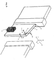
- the gate 1 slides on a linear track from an open position to a closed position, encountering the obstacle 2 at the closing point.
- the gate is actuated by the driving unit 3 with a speed V x 9 and is controlled by the unit 4, here represented for the sake of simplicity as an integral part of the control unit of the driving unit 3.
- the first part of the control method is thus represented in fig. 2 : the activation unit 25 manages the activation logic, described hereafter, by sending an obstacle signal to the control unit of the motor 4, based on a series of suitably processed and treated input signals. Some of these signals are generated by the accelerometer 5, while others are generated directly by the control unit of the motor 3.
- the input signal 7, proportional to the horizontal acceleration (A x ) of the gate 1, has a high pass filter 10 applied to it, with limit frequency f1 and a low pass filter 11 with limit frequency f2.
- the signal sampled is thus rebuilt with a rebuilder 13 FOH, to be transmitted to the unit 25.
- the signal 8, proportional to the vertical acceleration A z of the gate 1 has a high pass filter 22 applied to it, with limit frequency f 3 and a low pass filter 23, with limit frequency f 4 , also rebuilt with a rebuilder 13.
- the two signals of the accelerometer are thus acquired independently from each other and parametrised by the activation unit. These signals are not however sufficient to ensure adequate robustness of the activation criterion: it is thus suitable to carry out an integration of the horizontal acceleration signal, which creates a signal 12 through the integrator 15 and then once again filter, with a high pass filter 16, the signal that, rebuilt through the rebuilder 13, will be proportional to the variation in speed of displacement 17 of the gate in the direction of the obstacle.
- Another condition for identifying the obstacle interception situation is given by the analysis of the actual manoeuvring speed 18, which is made possible through the acquisition of a signal provided by the control unit of the motor, filtered with a low pass filter 19 and compared with a lower limit value V x,TH .
- the parameter of the reference speed 21 is used which, if greater than a certain value, identifies the condition of the motor in operation.
- This parameter does not need any filtering, given that it is a parameter provided by the control unit 4 of the motor and it is assigned based on control commands of the unit itself.
- the unit 25 can apply the activation criteria, indicated in fig. 3 . It represents the 2 states, "ON" 29, relative to triggering equal to 1 as activation state, i.e. detection of the obstacle and "OFF" 28, relative to triggering equal to 0, i.e. no obstacle, respectively, as well as the switching criteria from one state to another.
- the criterion 26 is the criterion of passing from 28 to 29 and 27 is the criterion that vice versa goes from state 29 to 28.
- the criterion 26 comprises five different conditions to be satisfied simultaneously, three of them relating to parameters acquired by the accelerometer.
- the horizontal acceleration value A x,f 12 processed by the application of at least one filter must be less than or equal to a certain threshold A x , TH , with the acceleration being considered negative with respect to the longitudinal reference axis and a condition of reduction of the speed in the direction of motion.
- the value A z,m 24 of the vertical acceleration processed by the application of at least one filter must be less than a threshold A z , TH , this being a typical condition linked to vertical interference not resulting from a true obstacle.
- the integration in time of the acceleration A x 12 processed i.e. the variation in speed V x 17, must be below the threshold V x,TH .
- the other two conditions are, on the other hand, provided by parameters acquired by the control unit of the motor 4, given that it is a reference speed 21 assigned based on the operating or stop state of the motor and on a signal 20 proportional to the actual instantaneous speed of the gate acquired through an encoder or similar, not represented here for the sake of simplicity.
- the criterion 27 for switching the trigger from 1 to 0 is simpler, since it is given by a single condition being satisfied, i.e. the decrease in speed 20 below a threshold Speede TH low, which represents the situation of the motor being stopped, faced with which it makes no sense to provide any reaction to the collision.
- Fig. 4 represents a graph of the reaction forces expressed in Newtons and measured as the effect of the impact of the gate as a function of time in seconds, in the state of the art and with the described method.
- the time to represents the moment of activation of all three different methods, here compared based on experimental measurements.
- the curve 31 represents the variation of the force according to the conventional activation method, with the application of a rubber damping rib on the contact edge: it is clear that there is a significant reaction time delay (t 0 -t 1 ), where t 1 is the moment of contact and t 0 is the moment of activation, even if the forces in play are limited within acceptable limits.
- the curve 32 represents the variation of the same interception method, but without a damping rib: it is clear that the reaction time (t 2 -t 0 ) is lower, but the maximum force peak obtained is excessive.
- the curve 33 represents, the variation of the force with the method of the present finding. It should be noted that without applying any damping element a high reactivity is obtained in terms of time (t 3 -t 0 ) and this also translates into an acceptable peak force.
- Fig. 5 represents this variant.
- the accelerometer is installed at the tip of the gate, with an axis parallel to the tangent to the trajectory of the gate 1.
Landscapes
- Control Of Position Or Direction (AREA)
- Power-Operated Mechanisms For Wings (AREA)
Abstract
Description
- The present finding concerns a method for detecting obstacles to be applied to a gate moving horizontally or pivoting about a vertical axis, according to the general part of
claim 1. - Gates are increasingly motorised by means of electrical actuation operators. Legislation in force obliges manufacturers to implement measures suitable for preventing and reducing the effects of a collision or crushing of people or things present in the manoeuvring area of the gate. The dangers connected with the motorised manoeuvring of a gate are many and partially protected by the application of photocells that recognise when people or objects pass during such manoeuvring. This protective measure, if applied by itself, is not however considered adequate to comply with the need to make a system safe. The reason for this is linked to the fact that it does not always protect against accidental contact between the mobile gate and possible obstacles present on its trajectory. For this reason the legislation offers the possibility of a mobile gate coming into contact with an obstacle, provided that the forces exerted on it are limited in terms of maximum peak and of application time. In particular, the peak of the force deriving from crushing must be kept below a maximum value of 400 N, while in a maximum time period of 5s the gate must substantially free the obstacle, exerting a residual force of no more than 25 N, measured using a load cell and a spring with predetermined elastic constant. For this purpose the manufacturers of motorisation systems have adopted numerous methods and implemented numerous devices suitable for reducing the operating forces through systems for recognising the condition of the motor's rotor being blocked or through application to the edges to be protected of deformable ribs equipped with pressure-sensitive elements (manometers, metallic cables kept under tension by spring systems that act on microswitches, pairs of photoelectric sensors, resistive profiles). The deformable ribs almost always manage to limit the forces exerted within acceptable limits, since the sensitive element is directly applied to the area involved in making contact with the obstacle and, being equipped with an elastic deformation section, dampen the reaction forces within acceptable limits, even if the reaction times of the control unit are long. In spite of this widely tested and verified efficiency, they have substantial drawbacks, linked to the fact that they must be applied to all the dangerous edges of the gate, which on a single sliding gate are two, but on a wing can even reach six, that the deformation varies as a function of the temperature and, last but not least, that they are aesthetically unacceptable. Moreover, the risk of shearing of a sliding gate with respect to the fixed pillars must be avoided through the use of another two fixed active ribs, without considering the wiring difficulties of a sliding mobile gate. For this reason, crushing-prevention safety is increasingly integrated in the controls of the actuation unit, as an inherent and undeactivatable element, if not through forcing of the programming of the control unit. In general, it is associated with an encoder control or with a limitation of the current delivered, suitable for detecting a blocked condition of the motor in different positions from the limit stop positions. The time needed to determine the blocked condition is a critical factor in carrying out a manoeuvre to disengage from the obstacle, thus limiting the reaction forces to the minimum. In the state of the art it can be estimated to be about 200 ms, which is an excessive value to limit the operating forces within an acceptable limit, with the consequence that it is almost always necessary to apply a deformable profile (called "passive rib") to the main edge and to the secondary edge of the gate, without however having to apply one of the sensors. Another drawback is linked to the fact that the obstacle recognition signal is not unequivocally associated with the real presence thereof. Poor maintenance conditions of the manufactured item, the wearing of the sliding guides and of the bearings, the accidental deformations of the gate due to various factors, can lead to "false obstacle" conditions; in other words, the actuation system carries out a safety manoeuvre, without it really being needed. This problem is usually solved in an "unorthodox" manner by installers and manufacturers, through a modification of the parameters of the control unit of the motor. Given that replacing a damaged or worn mechanical part is often economically disadvantageous, the sensitivity threshold of the control unit in the blocked condition is deliberately increased, with the real risk that safe operation is no longer guaranteed. These and other drawbacks cause manufacturers to implement devices that make the behaviour of the control unit more selective with respect to the blocked condition of the rotor. A solution widely quoted by prior art documents, but the practical implementation of which is not very common, is the use of an acceleration sensor applied to the part being manoeuvred and suitable for recognising the condition of contact with a foreign body on the stroke of the gate.
- Concerning this, the following patent documents should be quoted:
EP 1970516 A2 ,ES 1071173 U EP 2216478 A2 . - Document
EP1970516 A2 describes an example of application of an accelerometer fixedly connected to a pivoting gate, the motion of which is rotation-translation: the signal transduced varies as a function of the rotation, making it possible to determine both the position of the gate with respect to the open and closed positions, and the presence of obstacles through the analysis of the variation of the component orthogonal to the gate of the downward acceleration, normally equal to "g". DocumentES 1071173 U - The third document quoted above claims the same application to a vertical screen of the roller shutter or rolling door type, since the condition of an obstacle being present is established by the non-horizontal position of the last element of the gate, determined through an accelerometer precisely from the reduction of the vertical acceleration component, which, in normal conditions (i.e. in vertical position), is obviously equal to "g" or equal to a known component as a function of the position with respect to the vertical of the gate.
- None of the quoted documents claims the application to a gate moving horizontally, or a gate pivoting about a vertical axis and describes in detail the treatment of the signal and the solutions adopted in order to make the system completely immune from false obstacles. Moreover, the accelerometer is unable to replace other lifting systems, but can only integrate them in order to make the protection system more reactive and stronger, anticipating the interception event of the obstacle, reducing the reaction times and the forces in play.
- It has also been found that the reaction time with conventional detection systems, i.e. those that intercept the blocked situation of the rotor, is about 200 ms. This is an excessive time period, since the forces exerted on the obstacle exceed the maximum allowable peak values. In practice, it is always necessary to apply a damping profile on the contact edge, generally but not exclusively consisting of a rubber profile with hollow section, the deformation of which anticipates and attenuates the effects of direct metal-on-metal contact. This effect is particularly significant in the case of horizontal sliding gates, the kinetic energy of which discharges completely and almost instantaneously at the moment of contact.
- The present finding thus proposes to make a method for detecting obstacles that comprises an at least bi-axial acceleration sensor and some treatment and processing steps of the signal aimed at anticipating the reaction to the collision and improving the robustness of the intervention criterion.
- The finding will now be described in detail, with reference to a particular embodiment thereof, given as an example and not for limiting purposes, with the help of the attached tables of drawings, where:
-
fig. 1 represents a motorised sliding gate with horizontal rectilinear movement, to which the method according to the finding is applied: it represents an accelerometer and the directions of detection of the acceleration signal, the direction of motion of the gate and an obstacle to be intercepted, as well as the control unit and the driving unit; -
fig. 2 represents a block diagram of treatment and of processing of the signals generated by the sensors upstream of the control unit; -
fig. 3 represents the parameters processed and the criteria applied for the activation of the reaction to the collision; -
fig. 4 represents a comparative graph of the behaviour at collision of the conventional detection method and that according to the finding; -
fig. 5 represents a motorised sliding gate pivoting about a vertical axis, to which the method according to the finding is applied; the same elements corresponding to the gate with rectilinear movement according tofig. 1 can be seen. - With reference to
fig.1 , thegate 1 slides on a linear track from an open position to a closed position, encountering theobstacle 2 at the closing point. The gate is actuated by the driving unit 3 with aspeed V x 9 and is controlled by theunit 4, here represented for the sake of simplicity as an integral part of the control unit of the driving unit 3. Integral with thegate 1 there is theaccelerometer sensor 5, which detects thehorizontal acceleration A x 7 and vertical acceleration Az 8, along the axes x, z represented by the reference system 6 integral with the gate and oriented with the axis x in the closing direction. - The first part of the control method is thus represented in
fig. 2 : theactivation unit 25 manages the activation logic, described hereafter, by sending an obstacle signal to the control unit of themotor 4, based on a series of suitably processed and treated input signals. Some of these signals are generated by theaccelerometer 5, while others are generated directly by the control unit of the motor 3. Theinput signal 7, proportional to the horizontal acceleration (Ax) of thegate 1, has ahigh pass filter 10 applied to it, with limit frequency f1 and alow pass filter 11 with limit frequency f2. The signal sampled is thus rebuilt with arebuilder 13 FOH, to be transmitted to theunit 25. Similarly, the signal 8, proportional to the vertical acceleration Az of thegate 1, has a high pass filter 22 applied to it, with limit frequency f3 and alow pass filter 23, with limit frequency f4, also rebuilt with arebuilder 13. The two signals of the accelerometer are thus acquired independently from each other and parametrised by the activation unit. These signals are not however sufficient to ensure adequate robustness of the activation criterion: it is thus suitable to carry out an integration of the horizontal acceleration signal, which creates asignal 12 through theintegrator 15 and then once again filter, with ahigh pass filter 16, the signal that, rebuilt through therebuilder 13, will be proportional to the variation in speed ofdisplacement 17 of the gate in the direction of the obstacle. - Another condition for identifying the obstacle interception situation is given by the analysis of the
actual manoeuvring speed 18, which is made possible through the acquisition of a signal provided by the control unit of the motor, filtered with alow pass filter 19 and compared with a lower limit value Vx,TH. - On the other hand, in order to determine the status of the driving unit 3 the parameter of the
reference speed 21 is used which, if greater than a certain value, identifies the condition of the motor in operation. This parameter does not need any filtering, given that it is a parameter provided by thecontrol unit 4 of the motor and it is assigned based on control commands of the unit itself. At this point, once the described signals have been acquired, theunit 25 can apply the activation criteria, indicated infig. 3 . It represents the 2 states, "ON" 29, relative to triggering equal to 1 as activation state, i.e. detection of the obstacle and "OFF" 28, relative to triggering equal to 0, i.e. no obstacle, respectively, as well as the switching criteria from one state to another. In particular 26 is the criterion of passing from 28 to 29 and 27 is the criterion that vice versa goes fromstate 29 to 28. Thecriterion 26 comprises five different conditions to be satisfied simultaneously, three of them relating to parameters acquired by the accelerometer. The horizontalacceleration value A x,f 12 processed by the application of at least one filter must be less than or equal to a certain threshold Ax,TH, with the acceleration being considered negative with respect to the longitudinal reference axis and a condition of reduction of the speed in the direction of motion. Thevalue A z,m 24 of the vertical acceleration processed by the application of at least one filter must be less than a threshold Az, TH, this being a typical condition linked to vertical interference not resulting from a true obstacle. Moreover, the integration in time of theacceleration A x 12 processed, i.e. the variation inspeed V x 17, must be below the threshold Vx,TH. The other two conditions are, on the other hand, provided by parameters acquired by the control unit of themotor 4, given that it is areference speed 21 assigned based on the operating or stop state of the motor and on asignal 20 proportional to the actual instantaneous speed of the gate acquired through an encoder or similar, not represented here for the sake of simplicity. - The
criterion 27 for switching the trigger from 1 to 0 is simpler, since it is given by a single condition being satisfied, i.e. the decrease inspeed 20 below a threshold SpeedeTH low, which represents the situation of the motor being stopped, faced with which it makes no sense to provide any reaction to the collision. -
Fig. 4 represents a graph of the reaction forces expressed in Newtons and measured as the effect of the impact of the gate as a function of time in seconds, in the state of the art and with the described method. The time to represents the moment of activation of all three different methods, here compared based on experimental measurements. - The
curve 31 represents the variation of the force according to the conventional activation method, with the application of a rubber damping rib on the contact edge: it is clear that there is a significant reaction time delay (t0-t1), where t1 is the moment of contact and t0 is the moment of activation, even if the forces in play are limited within acceptable limits. - The
curve 32, on the other hand, represents the variation of the same interception method, but without a damping rib: it is clear that the reaction time (t2-t0) is lower, but the maximum force peak obtained is excessive. - The
curve 33, on the other hand, represents, the variation of the force with the method of the present finding. It should be noted that without applying any damping element a high reactivity is obtained in terms of time (t3-t0) and this also translates into an acceptable peak force. - In light of what is described above it is clear that the finding makes it possible to avoid the quoted problems, substantially reducing the reaction time and at the same time eliminating the chance of detection of false obstacles.
- The same method is applicable without substantial variations also to motorisation systems of the type pivoting about a vertical axis, where the motion of the gate is always horizontal, whereas
acceleration A x 7 andspeed V x 9 are in this case tangent to the circular trajectory described by the gate in therotation 1 on thehinges 10.Fig. 5 represents this variant. The accelerometer is installed at the tip of the gate, with an axis parallel to the tangent to the trajectory of thegate 1. - For the treatment of the signal and the processing of the activation criteria the same considerations apply as for those for the gate with rectilinear movement. In the same way, it is possible to consider that the communication between the
acceleration sensor 5 and thecontrol unit 4 takes place with a one-way radio frequency transmission and that the data processing device, the filtering device or the activation unit are directly integrated in the control unit of the motorization.
Claims (6)
- METHOD FOR DETECTING OBSTACLES TO BE APPLIED TO A GATE MOVING HORIZONTALLY OR PIVOTING ABOUT A VERTICAL AXIS, such a gate (1) including at least one detection means (5) suitable for determining its acceleration, which comprises the steps in which:a) the detection means (5) determines the horizontal (7) and vertical (8) acceleration values of the gate (1), processes them and transmits them to an activation unit (25);b) the activation unit (25) compares the acceleration values with a range of predetermined values according to a predetermined criterion (26) and checks the status of the motor unit (3) through a control unit (4);c) the activation unit (25) sends an obstacle recognition signal to the control unit (4) of the gate (1);d) the control unit (4) commands a motor unit (3) to make a manoeuvre to avoid the obstacle (2),said method being characterised in that the activation criterion (26) is given by the contemporary presence of the following three conditions:- the value of the vertical acceleration (24) processed by the application of at least one filter is below a predetermined threshold (Az, TH);- the value of the horizontal acceleration (12) processed by the application of at least one filter is below a predetermined threshold (Ax, TH);- the horizontal speed variation (17) is below a predetemined threshold (Vx, TH).
- METHOD FOR DETECTING OBSTACLES, according to claim 1, characterised in that the maximum processed vertical acceleration (24), horizontal acceleration (12) and speed variation (17) are stored by the control unit (4) and by the activation unit (25) during an initial learning step.
- METHOD FOR DETECTING OBSTACLES, according to claim 1 or 2, characterised in that the criterion (26) also comprises a condition relative to the minimum speed (20) of the gate (1) and to the reference speed (21).
- METHOD FOR DETECTING OBSTACLES, according to one or more of the previous claims, characterised in that the activation condition of the unit (5) can be switched upon the reduction in speed (20) of the gate (1) according to criteria given by a condition (27), in which the speed (20) of the gate drops below a predetermined value.
- METHOD FOR DETECTING OBSTACLES, according to one or more of the previous claims, characterised in that the transmission between activation unit (25) and control unit (4) takes place in radio frequency.
- METHOD FOR DETECTING OBSTACLES, according to one or more of the previous claims, characterised in that the activation unit (25) is integrated in the control unit (4).
Applications Claiming Priority (1)
| Application Number | Priority Date | Filing Date | Title |
|---|---|---|---|
| ITVI20140035 | 2014-02-05 |
Publications (2)
| Publication Number | Publication Date |
|---|---|
| EP2905408A1 true EP2905408A1 (en) | 2015-08-12 |
| EP2905408B1 EP2905408B1 (en) | 2017-03-08 |
Family
ID=50487077
Family Applications (1)
| Application Number | Title | Priority Date | Filing Date |
|---|---|---|---|
| EP15153752.9A Active EP2905408B1 (en) | 2014-02-05 | 2015-02-04 | Method for detecting obstacles to be applied to a gate moving horizontally or pivoting about a vertical axis |
Country Status (1)
| Country | Link |
|---|---|
| EP (1) | EP2905408B1 (en) |
Cited By (1)
| Publication number | Priority date | Publication date | Assignee | Title |
|---|---|---|---|---|
| IT201800008011A1 (en) * | 2018-08-09 | 2020-02-09 | Gunnebo Entrance Control Ltd | SAFETY SENSING SWING GATE / DOOR UNIT HAVING A MOVING LEAF |
Citations (3)
| Publication number | Priority date | Publication date | Assignee | Title |
|---|---|---|---|---|
| EP1970516A2 (en) | 2007-03-15 | 2008-09-17 | BALLAN S.p.A. | Device for controlling the safety of a frame during its movement |
| ES1071173U (en) | 2009-06-30 | 2010-02-01 | Jcm Technologies, S.A. | Set of automatic vertical movement door (Machine-translation by Google Translate, not legally binding) |
| EP2216478A2 (en) | 2009-02-06 | 2010-08-11 | Somfy SAS | Method for detecting the presence of an element between a threshold of an opening and one end of a motorised home-automation screen |
-
2015
- 2015-02-04 EP EP15153752.9A patent/EP2905408B1/en active Active
Patent Citations (3)
| Publication number | Priority date | Publication date | Assignee | Title |
|---|---|---|---|---|
| EP1970516A2 (en) | 2007-03-15 | 2008-09-17 | BALLAN S.p.A. | Device for controlling the safety of a frame during its movement |
| EP2216478A2 (en) | 2009-02-06 | 2010-08-11 | Somfy SAS | Method for detecting the presence of an element between a threshold of an opening and one end of a motorised home-automation screen |
| ES1071173U (en) | 2009-06-30 | 2010-02-01 | Jcm Technologies, S.A. | Set of automatic vertical movement door (Machine-translation by Google Translate, not legally binding) |
Cited By (1)
| Publication number | Priority date | Publication date | Assignee | Title |
|---|---|---|---|---|
| IT201800008011A1 (en) * | 2018-08-09 | 2020-02-09 | Gunnebo Entrance Control Ltd | SAFETY SENSING SWING GATE / DOOR UNIT HAVING A MOVING LEAF |
Also Published As
| Publication number | Publication date |
|---|---|
| EP2905408B1 (en) | 2017-03-08 |
Similar Documents
| Publication | Publication Date | Title |
|---|---|---|
| US8177035B2 (en) | Elevator system which controls a value of overspeed | |
| KR100671726B1 (en) | Closure device with safety function | |
| CA2973510C (en) | Method for controlling a door arrangement, as well as a door arrangement of this kind and a safety device therefor | |
| US20050203690A1 (en) | Controlling device of a regulating device of a motor vehicle | |
| US20080263964A1 (en) | Method for controlling an electrical door drive | |
| US6315355B1 (en) | Method and apparatus for triggering a sliding and hinged sun roof | |
| CN101675202A (en) | Method and device for operating an electromechanical actuating device | |
| DE19623420A1 (en) | Device for the electronic monitoring of an adjustment drive arranged in a vehicle | |
| EP2905408B1 (en) | Method for detecting obstacles to be applied to a gate moving horizontally or pivoting about a vertical axis | |
| US5841083A (en) | Blocked door detection for an elevator system | |
| JP6810000B2 (en) | Pinching detection device | |
| US20170335616A1 (en) | Control Device for a Vehicle Having an Automatically Closing Hatch | |
| KR101406069B1 (en) | Method and apparatus for controlling sunroof of vehicle | |
| CN112041609B (en) | Optoelectronic safety device and method for monitoring machine movement | |
| US9856689B2 (en) | Method and device for determining the offset of an electric window lift system | |
| EP3191670B1 (en) | Control device and operating method for a closure drive, closure drive, and closure thus driven | |
| DE102010062673B4 (en) | Gate, locking device and method for detecting a blockage | |
| KR101667487B1 (en) | A device for controoling openning angle of the door in a car | |
| EP3647523B1 (en) | Overhead door comprising an operating system | |
| EP2727872A1 (en) | Method for operating a device to prevent uncontrolled movement of a lift car | |
| DE102012008086A1 (en) | Method for operating protection device to protect e.g. finger during moving window pane of vehicle, involves controlling drive depending on determination of presence of object in monitored areas and positional information of moving element | |
| EP1580861A2 (en) | Control automatism for the movement of a door | |
| CN107587833A (en) | A kind of Australia's formula roller shutter door control method | |
| JP6583726B2 (en) | Lifting device and moving vehicle | |
| CN110867823A (en) | Current self-adaptive overcurrent protection method and system based on load characteristics |
Legal Events
| Date | Code | Title | Description |
|---|---|---|---|
| PUAI | Public reference made under article 153(3) epc to a published international application that has entered the european phase |
Free format text: ORIGINAL CODE: 0009012 |
|
| AK | Designated contracting states |
Kind code of ref document: A1 Designated state(s): AL AT BE BG CH CY CZ DE DK EE ES FI FR GB GR HR HU IE IS IT LI LT LU LV MC MK MT NL NO PL PT RO RS SE SI SK SM TR |
|
| AX | Request for extension of the european patent |
Extension state: BA ME |
|
| 17P | Request for examination filed |
Effective date: 20151222 |
|
| RBV | Designated contracting states (corrected) |
Designated state(s): AL AT BE BG CH CY CZ DE DK EE ES FI FR GB GR HR HU IE IS IT LI LT LU LV MC MK MT NL NO PL PT RO RS SE SI SK SM TR |
|
| GRAP | Despatch of communication of intention to grant a patent |
Free format text: ORIGINAL CODE: EPIDOSNIGR1 |
|
| STAA | Information on the status of an ep patent application or granted ep patent |
Free format text: STATUS: GRANT OF PATENT IS INTENDED |
|
| INTG | Intention to grant announced |
Effective date: 20161123 |
|
| GRAS | Grant fee paid |
Free format text: ORIGINAL CODE: EPIDOSNIGR3 |
|
| GRAA | (expected) grant |
Free format text: ORIGINAL CODE: 0009210 |
|
| STAA | Information on the status of an ep patent application or granted ep patent |
Free format text: STATUS: THE PATENT HAS BEEN GRANTED |
|
| AK | Designated contracting states |
Kind code of ref document: B1 Designated state(s): AL AT BE BG CH CY CZ DE DK EE ES FI FR GB GR HR HU IE IS IT LI LT LU LV MC MK MT NL NO PL PT RO RS SE SI SK SM TR |
|
| REG | Reference to a national code |
Ref country code: GB Ref legal event code: FG4D |
|
| REG | Reference to a national code |
Ref country code: CH Ref legal event code: EP Ref country code: AT Ref legal event code: REF Ref document number: 873692 Country of ref document: AT Kind code of ref document: T Effective date: 20170315 |
|
| REG | Reference to a national code |
Ref country code: IE Ref legal event code: FG4D |
|
| REG | Reference to a national code |
Ref country code: DE Ref legal event code: R096 Ref document number: 602015001692 Country of ref document: DE |
|
| REG | Reference to a national code |
Ref country code: LT Ref legal event code: MG4D |
|
| REG | Reference to a national code |
Ref country code: NL Ref legal event code: MP Effective date: 20170308 |
|
| PG25 | Lapsed in a contracting state [announced via postgrant information from national office to epo] |
Ref country code: HR Free format text: LAPSE BECAUSE OF FAILURE TO SUBMIT A TRANSLATION OF THE DESCRIPTION OR TO PAY THE FEE WITHIN THE PRESCRIBED TIME-LIMIT Effective date: 20170308 Ref country code: FI Free format text: LAPSE BECAUSE OF FAILURE TO SUBMIT A TRANSLATION OF THE DESCRIPTION OR TO PAY THE FEE WITHIN THE PRESCRIBED TIME-LIMIT Effective date: 20170308 Ref country code: GR Free format text: LAPSE BECAUSE OF FAILURE TO SUBMIT A TRANSLATION OF THE DESCRIPTION OR TO PAY THE FEE WITHIN THE PRESCRIBED TIME-LIMIT Effective date: 20170609 Ref country code: LT Free format text: LAPSE BECAUSE OF FAILURE TO SUBMIT A TRANSLATION OF THE DESCRIPTION OR TO PAY THE FEE WITHIN THE PRESCRIBED TIME-LIMIT Effective date: 20170308 Ref country code: NO Free format text: LAPSE BECAUSE OF FAILURE TO SUBMIT A TRANSLATION OF THE DESCRIPTION OR TO PAY THE FEE WITHIN THE PRESCRIBED TIME-LIMIT Effective date: 20170608 |
|
| REG | Reference to a national code |
Ref country code: AT Ref legal event code: MK05 Ref document number: 873692 Country of ref document: AT Kind code of ref document: T Effective date: 20170308 |
|
| PG25 | Lapsed in a contracting state [announced via postgrant information from national office to epo] |
Ref country code: LV Free format text: LAPSE BECAUSE OF FAILURE TO SUBMIT A TRANSLATION OF THE DESCRIPTION OR TO PAY THE FEE WITHIN THE PRESCRIBED TIME-LIMIT Effective date: 20170308 Ref country code: RS Free format text: LAPSE BECAUSE OF FAILURE TO SUBMIT A TRANSLATION OF THE DESCRIPTION OR TO PAY THE FEE WITHIN THE PRESCRIBED TIME-LIMIT Effective date: 20170308 Ref country code: ES Free format text: LAPSE BECAUSE OF FAILURE TO SUBMIT A TRANSLATION OF THE DESCRIPTION OR TO PAY THE FEE WITHIN THE PRESCRIBED TIME-LIMIT Effective date: 20170308 Ref country code: BG Free format text: LAPSE BECAUSE OF FAILURE TO SUBMIT A TRANSLATION OF THE DESCRIPTION OR TO PAY THE FEE WITHIN THE PRESCRIBED TIME-LIMIT Effective date: 20170608 Ref country code: SE Free format text: LAPSE BECAUSE OF FAILURE TO SUBMIT A TRANSLATION OF THE DESCRIPTION OR TO PAY THE FEE WITHIN THE PRESCRIBED TIME-LIMIT Effective date: 20170308 |
|
| PG25 | Lapsed in a contracting state [announced via postgrant information from national office to epo] |
Ref country code: NL Free format text: LAPSE BECAUSE OF FAILURE TO SUBMIT A TRANSLATION OF THE DESCRIPTION OR TO PAY THE FEE WITHIN THE PRESCRIBED TIME-LIMIT Effective date: 20170308 |
|
| PG25 | Lapsed in a contracting state [announced via postgrant information from national office to epo] |
Ref country code: EE Free format text: LAPSE BECAUSE OF FAILURE TO SUBMIT A TRANSLATION OF THE DESCRIPTION OR TO PAY THE FEE WITHIN THE PRESCRIBED TIME-LIMIT Effective date: 20170308 Ref country code: AT Free format text: LAPSE BECAUSE OF FAILURE TO SUBMIT A TRANSLATION OF THE DESCRIPTION OR TO PAY THE FEE WITHIN THE PRESCRIBED TIME-LIMIT Effective date: 20170308 Ref country code: RO Free format text: LAPSE BECAUSE OF FAILURE TO SUBMIT A TRANSLATION OF THE DESCRIPTION OR TO PAY THE FEE WITHIN THE PRESCRIBED TIME-LIMIT Effective date: 20170308 Ref country code: SK Free format text: LAPSE BECAUSE OF FAILURE TO SUBMIT A TRANSLATION OF THE DESCRIPTION OR TO PAY THE FEE WITHIN THE PRESCRIBED TIME-LIMIT Effective date: 20170308 Ref country code: CZ Free format text: LAPSE BECAUSE OF FAILURE TO SUBMIT A TRANSLATION OF THE DESCRIPTION OR TO PAY THE FEE WITHIN THE PRESCRIBED TIME-LIMIT Effective date: 20170308 |
|
| PG25 | Lapsed in a contracting state [announced via postgrant information from national office to epo] |
Ref country code: SM Free format text: LAPSE BECAUSE OF FAILURE TO SUBMIT A TRANSLATION OF THE DESCRIPTION OR TO PAY THE FEE WITHIN THE PRESCRIBED TIME-LIMIT Effective date: 20170308 Ref country code: PL Free format text: LAPSE BECAUSE OF FAILURE TO SUBMIT A TRANSLATION OF THE DESCRIPTION OR TO PAY THE FEE WITHIN THE PRESCRIBED TIME-LIMIT Effective date: 20170308 Ref country code: IS Free format text: LAPSE BECAUSE OF FAILURE TO SUBMIT A TRANSLATION OF THE DESCRIPTION OR TO PAY THE FEE WITHIN THE PRESCRIBED TIME-LIMIT Effective date: 20170708 Ref country code: PT Free format text: LAPSE BECAUSE OF FAILURE TO SUBMIT A TRANSLATION OF THE DESCRIPTION OR TO PAY THE FEE WITHIN THE PRESCRIBED TIME-LIMIT Effective date: 20170710 |
|
| REG | Reference to a national code |
Ref country code: DE Ref legal event code: R097 Ref document number: 602015001692 Country of ref document: DE |
|
| REG | Reference to a national code |
Ref country code: FR Ref legal event code: PLFP Year of fee payment: 4 |
|
| PLBE | No opposition filed within time limit |
Free format text: ORIGINAL CODE: 0009261 |
|
| STAA | Information on the status of an ep patent application or granted ep patent |
Free format text: STATUS: NO OPPOSITION FILED WITHIN TIME LIMIT |
|
| PG25 | Lapsed in a contracting state [announced via postgrant information from national office to epo] |
Ref country code: DK Free format text: LAPSE BECAUSE OF FAILURE TO SUBMIT A TRANSLATION OF THE DESCRIPTION OR TO PAY THE FEE WITHIN THE PRESCRIBED TIME-LIMIT Effective date: 20170308 |
|
| 26N | No opposition filed |
Effective date: 20171211 |
|
| PG25 | Lapsed in a contracting state [announced via postgrant information from national office to epo] |
Ref country code: SI Free format text: LAPSE BECAUSE OF FAILURE TO SUBMIT A TRANSLATION OF THE DESCRIPTION OR TO PAY THE FEE WITHIN THE PRESCRIBED TIME-LIMIT Effective date: 20170308 |
|
| REG | Reference to a national code |
Ref country code: CH Ref legal event code: PL |
|
| PG25 | Lapsed in a contracting state [announced via postgrant information from national office to epo] |
Ref country code: MC Free format text: LAPSE BECAUSE OF FAILURE TO SUBMIT A TRANSLATION OF THE DESCRIPTION OR TO PAY THE FEE WITHIN THE PRESCRIBED TIME-LIMIT Effective date: 20170308 |
|
| REG | Reference to a national code |
Ref country code: IE Ref legal event code: MM4A |
|
| REG | Reference to a national code |
Ref country code: BE Ref legal event code: MM Effective date: 20180228 |
|
| PG25 | Lapsed in a contracting state [announced via postgrant information from national office to epo] |
Ref country code: CH Free format text: LAPSE BECAUSE OF NON-PAYMENT OF DUE FEES Effective date: 20180228 Ref country code: LU Free format text: LAPSE BECAUSE OF NON-PAYMENT OF DUE FEES Effective date: 20180204 Ref country code: LI Free format text: LAPSE BECAUSE OF NON-PAYMENT OF DUE FEES Effective date: 20180228 |
|
| PG25 | Lapsed in a contracting state [announced via postgrant information from national office to epo] |
Ref country code: IE Free format text: LAPSE BECAUSE OF NON-PAYMENT OF DUE FEES Effective date: 20180204 |
|
| PG25 | Lapsed in a contracting state [announced via postgrant information from national office to epo] |
Ref country code: BE Free format text: LAPSE BECAUSE OF NON-PAYMENT OF DUE FEES Effective date: 20180228 |
|
| GBPC | Gb: european patent ceased through non-payment of renewal fee |
Effective date: 20190204 |
|
| PG25 | Lapsed in a contracting state [announced via postgrant information from national office to epo] |
Ref country code: MT Free format text: LAPSE BECAUSE OF NON-PAYMENT OF DUE FEES Effective date: 20180204 Ref country code: GB Free format text: LAPSE BECAUSE OF NON-PAYMENT OF DUE FEES Effective date: 20190204 |
|
| PG25 | Lapsed in a contracting state [announced via postgrant information from national office to epo] |
Ref country code: TR Free format text: LAPSE BECAUSE OF FAILURE TO SUBMIT A TRANSLATION OF THE DESCRIPTION OR TO PAY THE FEE WITHIN THE PRESCRIBED TIME-LIMIT Effective date: 20170308 |
|
| PG25 | Lapsed in a contracting state [announced via postgrant information from national office to epo] |
Ref country code: HU Free format text: LAPSE BECAUSE OF FAILURE TO SUBMIT A TRANSLATION OF THE DESCRIPTION OR TO PAY THE FEE WITHIN THE PRESCRIBED TIME-LIMIT; INVALID AB INITIO Effective date: 20150204 Ref country code: MK Free format text: LAPSE BECAUSE OF NON-PAYMENT OF DUE FEES Effective date: 20170308 Ref country code: CY Free format text: LAPSE BECAUSE OF FAILURE TO SUBMIT A TRANSLATION OF THE DESCRIPTION OR TO PAY THE FEE WITHIN THE PRESCRIBED TIME-LIMIT Effective date: 20170308 |
|
| PG25 | Lapsed in a contracting state [announced via postgrant information from national office to epo] |
Ref country code: AL Free format text: LAPSE BECAUSE OF FAILURE TO SUBMIT A TRANSLATION OF THE DESCRIPTION OR TO PAY THE FEE WITHIN THE PRESCRIBED TIME-LIMIT Effective date: 20170308 |
|
| PGFP | Annual fee paid to national office [announced via postgrant information from national office to epo] |
Ref country code: DE Payment date: 20260119 Year of fee payment: 12 |
|
| PGFP | Annual fee paid to national office [announced via postgrant information from national office to epo] |
Ref country code: IT Payment date: 20260116 Year of fee payment: 12 |
|
| PGFP | Annual fee paid to national office [announced via postgrant information from national office to epo] |
Ref country code: FR Payment date: 20260116 Year of fee payment: 12 |