EP2905407A1 - Valve device for a hydraulic door closer - Google Patents
Valve device for a hydraulic door closer Download PDFInfo
- Publication number
- EP2905407A1 EP2905407A1 EP15151755.4A EP15151755A EP2905407A1 EP 2905407 A1 EP2905407 A1 EP 2905407A1 EP 15151755 A EP15151755 A EP 15151755A EP 2905407 A1 EP2905407 A1 EP 2905407A1
- Authority
- EP
- European Patent Office
- Prior art keywords
- valve
- thread
- valve body
- adjustment
- cap
- Prior art date
- Legal status (The legal status is an assumption and is not a legal conclusion. Google has not performed a legal analysis and makes no representation as to the accuracy of the status listed.)
- Granted
Links
- 239000012530 fluid Substances 0.000 claims abstract description 27
- 238000004891 communication Methods 0.000 claims abstract description 4
- 238000013016 damping Methods 0.000 claims description 8
- 238000000034 method Methods 0.000 claims description 8
- 239000011295 pitch Substances 0.000 claims description 7
- 230000000694 effects Effects 0.000 description 6
- 230000002596 correlated effect Effects 0.000 description 4
- 238000004519 manufacturing process Methods 0.000 description 4
Images



Classifications
-
- E—FIXED CONSTRUCTIONS
- E05—LOCKS; KEYS; WINDOW OR DOOR FITTINGS; SAFES
- E05F—DEVICES FOR MOVING WINGS INTO OPEN OR CLOSED POSITION; CHECKS FOR WINGS; WING FITTINGS NOT OTHERWISE PROVIDED FOR, CONCERNED WITH THE FUNCTIONING OF THE WING
- E05F3/00—Closers or openers with braking devices, e.g. checks; Construction of pneumatic or liquid braking devices
- E05F3/04—Closers or openers with braking devices, e.g. checks; Construction of pneumatic or liquid braking devices with liquid piston brakes
- E05F3/12—Special devices controlling the circulation of the liquid, e.g. valve arrangement
-
- F—MECHANICAL ENGINEERING; LIGHTING; HEATING; WEAPONS; BLASTING
- F16—ENGINEERING ELEMENTS AND UNITS; GENERAL MEASURES FOR PRODUCING AND MAINTAINING EFFECTIVE FUNCTIONING OF MACHINES OR INSTALLATIONS; THERMAL INSULATION IN GENERAL
- F16K—VALVES; TAPS; COCKS; ACTUATING-FLOATS; DEVICES FOR VENTING OR AERATING
- F16K1/00—Lift valves or globe valves, i.e. cut-off apparatus with closure members having at least a component of their opening and closing motion perpendicular to the closing faces
- F16K1/32—Details
- F16K1/50—Preventing rotation of valve members
-
- F—MECHANICAL ENGINEERING; LIGHTING; HEATING; WEAPONS; BLASTING
- F16—ENGINEERING ELEMENTS AND UNITS; GENERAL MEASURES FOR PRODUCING AND MAINTAINING EFFECTIVE FUNCTIONING OF MACHINES OR INSTALLATIONS; THERMAL INSULATION IN GENERAL
- F16K—VALVES; TAPS; COCKS; ACTUATING-FLOATS; DEVICES FOR VENTING OR AERATING
- F16K35/00—Means to prevent accidental or unauthorised actuation
Definitions
- the present invention is related to a valve device for a hydraulic door closer, a valve cap for use in a valve device, a hydraulic door closer as well as a method for securing a valve position of a valve body of a valve device.
- valve devices are used to regulate the flow of hydraulic fluid within the door closer. Therefore, the movement of the door in the opening position as well as in the closing position can be damped by defined flow of fluid through the valve device.
- the valve device commonly known comprises valve entrances and valve exits to let a fluid flow through a valve channel extending between the valve entrance and the valve exit.
- a valve body of commonly known valve devices can be moved between different valve positions offering different passage areas for passing fluid around the valve body.
- it usually comprises an adjustment thread. By rotating the valve body relative to the thread axis of the adjustment thread, the valve body can be moved up or down between the different valve positions.
- valve devices have a great disadvantage as to their use over long time periods.
- a variation of the valve position takes a place in an undesired manner.
- the respective hydraulic fluid flows through the valve channel.
- pressure is built up against the valve position of the valve body.
- This could lead to an unwillingly rotation of the valve body in the outside direction, therefore leading to a variation of the passage area of the valve position.
- the variation of the valve position correlates with a variation of the damping effect.
- Commonly known valve devices deal with that problem by providing for example rotation stoppers to the valve body.
- a respective solution is for example shown in DE 20 2007 004 104 U1 . Such solutions have the great disadvantage of higher manufacturing complexity and costs.
- valve device according to independent claim 1
- valve cap according to independent claim 7
- hydraulic door closer according to independent claim 8
- the valve device for a door closer comprises a valve entrance and a valve exit.
- a valve channel offers fluid communication between the valve entrance and the valve exit.
- the valve device comprises a valve body, with an adjustment thread which is ranged within the valve channel and movable by the adjustment thread between a first valve position with a first passage area and at least a second valve position with a second passage area.
- An inventive valve device is characterized in that a valve cap is arranged with a contact surface contacting a counter surface of the valve body.
- the valve cap comprises a securing thread with a contrary thread direction compared to the adjustment thread for counter bearing of the valve body.
- An inventive valve device can comprise a commonly known valve body. This is used by an adjustment thread to be moved between different valve positions. Each valve position comprises an own passage area, thereby defining different square surfaces for passing the fluid flow of the hydraulic fluid. This leads to different valve positions correlating with different damping effects of the hydraulic door closer. To achieve a variation of the damping effect the valve body is rotated relative to a thread axis of the adjustment thread and thereby moved between different valve positions. According to the present invention, the variation of the valve position can now be secured by the valve cap. Therefore, the valve cap is a separate element relative to the valve body. After moving the valve body by the use of the adjustment thread in the respective valve position, the valve cap is used for the securing step.
- valve cap is also rotated relative to its thread axis of the securing thread.
- the rotation of the valve cap takes place in the contrary rotation direction relatively to the rotation of the valve body. Therefore, the valve cap offers a securing counter element for the valve body. The rotation of the valve cap takes place until a contact of a counter contact surface of the valve body.
- Different contact surfaces of the valve body as well as of the valve cap can comprise different geometrical extensions.
- the respective contact surfaces have a flat extension.
- the respective valve position of the valve body is secured by the valve cap. If in this case now the pressure increases within the valve channel by passing fluid, this increasing force can be secured not only by the adjustment thread with a valve body but also via the contact surfaces over the valve cap and the securing thread. A movement in the outside direction for a variation of the valve position by the increasing fluid flow is no longer possible. This is based on the fact that the securing thread and the adjustment thread comprise different thread directions. If such a fluid flow would tent to rotate the valve body around the thread axis of the adjustment thread this leads to a inline rotation in the same direction of rotation of the valve cap by the meaning of friction between the contact surfaces of the valve cap and the valve body. Due to the fact that the valve cap comprises the securing surface with a contrary thread direction, this leads to a counter force against the force of the increased pressure inside the valve channel.
- the valve cap comprises an easy to manufacture element, because it is separate from the valve body. Moreover, the method for securing the valve body in the respective valve position is to be carried out easily and in particular without detailed and defined instructions. All a person has to do is to place the respective valve cap and rotate it in a commonly known manner.
- a valve device which can for example be part of the housing of a hydraulic door closer or comprises an own housing
- respective counter threads for the adjustment thread namely a counter adjustment thread
- for the securing thread namely a counter securing thread
- these threads comprise different diameters.
- the adjustment thread and the counter adjustment thread comprise a smaller diameter than the securing thread and the counter securing thread.
- a valve device is characterized in that the adjustment thread and the securing thread comprise the same or at least the same thread pitches with contrary thread directions, in particular standard thread pitches.
- the thread pitches are identical in particular standard identical thread pitches for example metrical thread pitches. This leads to a further simplification of an inventive valve device and to reduced costs of manufacturing.
- an inventive valve device is characterized in that the adjustment thread and the securing thread comprise parallel or at least parallel oriented thread axis, in particular a common thread axis.
- Such an orientation leads to the advantage that a person using an inventive valve device a tool oriented in the same common or parallel orientation. This leads on one hand to easier rotation and thereby to easier handling of an inventive valve device.
- the manufacturing of the inventive valve device, in particular the different threads and the different counter threads is easier and more cost efficient.
- the valve device is characterized in that the valve cap comprises a centration surface with different extension compared to the contact surface, contacting a counter centration surface of the valve body.
- the valve cap comprises a centration surface with different extension compared to the contact surface, contacting a counter centration surface of the valve body.
- an inventive valve device can be characterized in that the valve cap comprises an adjustment opening, opening a passage way to an adjustment interface of the valve body.
- An adjustment interface can for example be a respective surface area which can be correlated with a tool head, for example a screw driver.
- the adjustment interface therefore comprises a defined geometrical extension, correlating with the respective tool head.
- the adjustment opening is in particular configured with a greater diameter than the respective necessary tool head for the adjustment interface.
- an inventive valve device is characterized in that the valve body comprises a handling interface for turning the valve cap relative to a thread axis of the securing thread.
- a handling interface can also be configured with a geometrical defined extension, for example correlating with a screw driver interface. Thereby, the handling interface is used to carry out the rotation and thereby the securing movement of the valve cap in an easy and fast manner.
- a further aspect of the present invention comprises a valve cap for use in a valve device according to the present invention.
- a valve cap is characterized in that it comprises a contact surface for contacting the counter contact surface of a valve body of the valve device.
- the valve cap further comprises a securing thread with a contrary thread direction compared to an adjustment thread of the valve body for counter bearing the valve body.
- a further aspect of the present invention is a hydraulic door closer comprising a fluid system for damping the closing movement and/or the opening movement of a door.
- An inventive hydraulic door closer is characterized in that the fluid system comprises at least one valve device according to the present invention.
- the inventive hydraulic door closer leads to the same advantages which have been discussed in detail with respect to the inventive valve device.
- An inventive hydraulic door closer can be further be characterized in that the fluid system comprises two inventive valve devices, one valve device for the opening movement of the door and one valve device for the closing movement of the door.
- the fluid system comprises two inventive valve devices, one valve device for the opening movement of the door and one valve device for the closing movement of the door.
- two different valve channels are offered by the fluid system, one for a first flow direction for the opening movement of the door and one with a second flow direction with a correlation to the closing movement of the door.
- a further aspect of the present invention is focused on a method of securing a valve position of a valve body of a valve device, in particular according to the present invention, comprising the following steps:
- Fig. 1 to 3 show a first embodiment of an inventive valve device 10.
- the valve device comprises within a housing a valve entrance 20 as well as a valve exit 30.
- the two openings of the valve entrance 20 and the valve exit 30 are in fluid communication with each other via a valve channel 40. Hydraulic fluid can flow into the valve entrance 20 passing a valve body 50 which is offering a passage area around the valve body 50 and flow through the valve channel 40 out of the valve exit 30.
- the valve body 50 can be moved upwards and downwards along a movement axis which is correlated with a thread axis 52a of an adjustment thread 52.
- the movement of adjusting valve positions of the valve body 50 is carried out by rotation of the valve body 50.
- a tool head can be used to correlate with an adjustment interface 58 to carry out the rotation of the valve body 50 relative to the thread axis 52a.
- the thread axis 62a of the securing thread 62 is common and parallel with the thread axis 52a of the adjustment thread 52.
- the rotation of the valve cap 60 is carried out until the contact surface 62 of the valve cap contacts the counter contact surface 54 of the valve body.
- valve channel 40 During use of a respective hydraulic door closer 100, fluid of the hydraulic fluid can flow through the valve channel 40. This can lead to an increase of flow and fluid pressure inside of the valve channel tending the valve body 50 to move upwards in Fig. 2 .
- the upward movement could take place by a forced rotation of the valve body 50 around the thread axis 52a of the adjustment thread 52. Due to the fact that the counter contact surface 54 of the valve body 50 is in contact with a contact surface 64 of the valve cap 60, via frictional forces this rotational movement of valve body 50 would be transferred to a rotational movement of the valve cap 60 in the same direction.
- Fig. 4 and 5 disclose further embodiment of the valve devices 10, which are here positioned in an inventive hydraulic door closer 100.
- This door closer 100 comprises a damping functionality for the movement in the opening as well as in the closing direction. Due to the fact that two separate valve devices 10 according to the present invention are used the two different movements can be configured with different variations of the damping effect by giving different valve positions P1 and P2 for the two separate valve devices 10.
- Fig. 6 and 7 show an embodiment of an inventive valve cap 60.
- the valve cap 60 comprises an adjustment opening 68, opening a passage way to a respective adjustment interface 58 of the valve body.
- the securing thread 62 is an outer thread.
- the two different orientated surfaces namely the contact surface 64 as well as the centration surface 66 can be seen.
- a handling interface 61 can be seen, which correlates with the head of a screw driver to carry out the securing movement, namely the rotation relative to the securing axis.
Landscapes
- Engineering & Computer Science (AREA)
- General Engineering & Computer Science (AREA)
- Mechanical Engineering (AREA)
- Lift Valve (AREA)
- Fluid-Damping Devices (AREA)
- Mechanically-Actuated Valves (AREA)
Abstract
Description
- The present invention is related to a valve device for a hydraulic door closer, a valve cap for use in a valve device, a hydraulic door closer as well as a method for securing a valve position of a valve body of a valve device.
- It is known, that in hydraulic door users valve devices are used to regulate the flow of hydraulic fluid within the door closer. Therefore, the movement of the door in the opening position as well as in the closing position can be damped by defined flow of fluid through the valve device. To allow a variation of the damping effect for the closing and the opening movement of the door, the valve device commonly known comprises valve entrances and valve exits to let a fluid flow through a valve channel extending between the valve entrance and the valve exit. A valve body of commonly known valve devices can be moved between different valve positions offering different passage areas for passing fluid around the valve body. To move the valve body between different valve positions, it usually comprises an adjustment thread. By rotating the valve body relative to the thread axis of the adjustment thread, the valve body can be moved up or down between the different valve positions.
- Commonly known valve devices have a great disadvantage as to their use over long time periods. In particular, in cases with large pressure during the use of the hydraulic door closer, it can happen that a variation of the valve position takes a place in an undesired manner. For example, during a door closing or door opening movement, the respective hydraulic fluid flows through the valve channel. By carrying out this fluid flow, pressure is built up against the valve position of the valve body. This could lead to an unwillingly rotation of the valve body in the outside direction, therefore leading to a variation of the passage area of the valve position. In this case, the variation of the valve position correlates with a variation of the damping effect. Commonly known valve devices deal with that problem by providing for example rotation stoppers to the valve body. A respective solution is for example shown in
DE 20 2007 004 104 U1 - Therefore, it is an object of the present invention to solve aforesaid problems at least partly. In particular, it is an object of the present invention to provide in a cost efficient and easy manner a valve device which is secured against unwillingly moving or changing of the valve positions.
- Aforesaid problem is solved by a valve device according to independent claim 1, a valve cap according to independent claim 7, a hydraulic door closer according to independent claim 8 as well as a method according to
independent claim 10. Features and details of the present invention result from the subclaims, the description and the respective drawings. Features and details discussed with respect to the inventive valve device therefore are also correlated with features and details as to the valve cap, the hydraulic door closer and the method. - According to the present invention, the valve device for a door closer comprises a valve entrance and a valve exit. A valve channel offers fluid communication between the valve entrance and the valve exit. Further, the valve device comprises a valve body, with an adjustment thread which is ranged within the valve channel and movable by the adjustment thread between a first valve position with a first passage area and at least a second valve position with a second passage area. An inventive valve device is characterized in that a valve cap is arranged with a contact surface contacting a counter surface of the valve body. Moreover, the valve cap comprises a securing thread with a contrary thread direction compared to the adjustment thread for counter bearing of the valve body.
- An inventive valve device can comprise a commonly known valve body. This is used by an adjustment thread to be moved between different valve positions. Each valve position comprises an own passage area, thereby defining different square surfaces for passing the fluid flow of the hydraulic fluid. This leads to different valve positions correlating with different damping effects of the hydraulic door closer. To achieve a variation of the damping effect the valve body is rotated relative to a thread axis of the adjustment thread and thereby moved between different valve positions. According to the present invention, the variation of the valve position can now be secured by the valve cap. Therefore, the valve cap is a separate element relative to the valve body. After moving the valve body by the use of the adjustment thread in the respective valve position, the valve cap is used for the securing step. To achieve this, the valve cap is also rotated relative to its thread axis of the securing thread. The rotation of the valve cap takes place in the contrary rotation direction relatively to the rotation of the valve body. Therefore, the valve cap offers a securing counter element for the valve body. The rotation of the valve cap takes place until a contact of a counter contact surface of the valve body.
- Different contact surfaces of the valve body as well as of the valve cap can comprise different geometrical extensions. In particular, the respective contact surfaces have a flat extension.
- By the use of an inventive valve device, the respective valve position of the valve body is secured by the valve cap. If in this case now the pressure increases within the valve channel by passing fluid, this increasing force can be secured not only by the adjustment thread with a valve body but also via the contact surfaces over the valve cap and the securing thread. A movement in the outside direction for a variation of the valve position by the increasing fluid flow is no longer possible. This is based on the fact that the securing thread and the adjustment thread comprise different thread directions. If such a fluid flow would tent to rotate the valve body around the thread axis of the adjustment thread this leads to a inline rotation in the same direction of rotation of the valve cap by the meaning of friction between the contact surfaces of the valve cap and the valve body. Due to the fact that the valve cap comprises the securing surface with a contrary thread direction, this leads to a counter force against the force of the increased pressure inside the valve channel.
- Based on the aforesaid information, the valve cap comprises an easy to manufacture element, because it is separate from the valve body. Moreover, the method for securing the valve body in the respective valve position is to be carried out easily and in particular without detailed and defined instructions. All a person has to do is to place the respective valve cap and rotate it in a commonly known manner.
- It is to be noted that in a valve device, which can for example be part of the housing of a hydraulic door closer or comprises an own housing, respective counter threads for the adjustment thread, namely a counter adjustment thread, and for the securing thread, namely a counter securing thread can be offered. For example these threads comprise different diameters. In particular, the adjustment thread and the counter adjustment thread comprise a smaller diameter than the securing thread and the counter securing thread. Thereby, the valve body can be moved through the counter securing thread of a respective housing of the valve device to be put in position for carrying out the adjustment movement by the adjustment thread.
- It is possible according to the present invention that a valve device is characterized in that the adjustment thread and the securing thread comprise the same or at least the same thread pitches with contrary thread directions, in particular standard thread pitches. In general, according to the present invention it is a core idea to present different threads with different directions of the thread. In particular, the thread pitches are identical in particular standard identical thread pitches for example metrical thread pitches. This leads to a further simplification of an inventive valve device and to reduced costs of manufacturing.
- It could further be of advantage if an inventive valve device is characterized in that the adjustment thread and the securing thread comprise parallel or at least parallel oriented thread axis, in particular a common thread axis. Such an orientation leads to the advantage that a person using an inventive valve device a tool oriented in the same common or parallel orientation. This leads on one hand to easier rotation and thereby to easier handling of an inventive valve device. Moreover, the manufacturing of the inventive valve device, in particular the different threads and the different counter threads is easier and more cost efficient.
- It could also be of advantage, if according to the present invention the valve device is characterized in that the valve cap comprises a centration surface with different extension compared to the contact surface, contacting a counter centration surface of the valve body. This leads to a situation where side translation movement of the valve cap and the valve body relative to each other is avoided. In particular, it leads to a higher surface contact and thereby to a higher friction force between the contacting valve cap and the valve body. The securing effect described in the introductory part of this application is thereby increased. Moreover, the centration surface can comprise a conical area, which is used for centering the valve cap by the movement into its securing position.
- Furthermore, an inventive valve device can be characterized in that the valve cap comprises an adjustment opening, opening a passage way to an adjustment interface of the valve body. An adjustment interface can for example be a respective surface area which can be correlated with a tool head, for example a screw driver. The adjustment interface therefore comprises a defined geometrical extension, correlating with the respective tool head. The adjustment opening is in particular configured with a greater diameter than the respective necessary tool head for the adjustment interface. Thereby, the tool head can be moved through the passage way formed by the adjustment opening to be correlated with the adjustment interface to carry out the adjustment movement of the valve body.
- Furthermore, it is of advantage if an inventive valve device is characterized in that the valve body comprises a handling interface for turning the valve cap relative to a thread axis of the securing thread. A handling interface can also be configured with a geometrical defined extension, for example correlating with a screw driver interface. Thereby, the handling interface is used to carry out the rotation and thereby the securing movement of the valve cap in an easy and fast manner.
- A further aspect of the present invention comprises a valve cap for use in a valve device according to the present invention. Such a valve cap is characterized in that it comprises a contact surface for contacting the counter contact surface of a valve body of the valve device. The valve cap further comprises a securing thread with a contrary thread direction compared to an adjustment thread of the valve body for counter bearing the valve body. The valve cap thereby leads to the same advantages which have been described in detail with respect to the valve device.
- A further aspect of the present invention is a hydraulic door closer comprising a fluid system for damping the closing movement and/or the opening movement of a door. An inventive hydraulic door closer is characterized in that the fluid system comprises at least one valve device according to the present invention. Thereby, the inventive hydraulic door closer leads to the same advantages which have been discussed in detail with respect to the inventive valve device.
- An inventive hydraulic door closer can be further be characterized in that the fluid system comprises two inventive valve devices, one valve device for the opening movement of the door and one valve device for the closing movement of the door. Thereby two different valve channels are offered by the fluid system, one for a first flow direction for the opening movement of the door and one with a second flow direction with a correlation to the closing movement of the door.
- A further aspect of the present invention is focused on a method of securing a valve position of a valve body of a valve device, in particular according to the present invention, comprising the following steps:
- Turning the valve body around a thread axis of an adjustment thread into a first valve position,
- Turning a valve cap around the thread axis of a securing thread until a contact surface of the valve cap contacts a counter contact surface of the valve body.
- An inventive method leads to the same advantages which have already been discussed in detail with respect to the inventive valve device.
- The present invention is further described in detail with respect to the accompanying drawings. Features discussed within the description of the drawings can be combined with each other freely. The figures schematically:
-
Fig. 1 a first embodiment of an inventive valve device, -
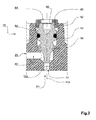
Fig. 2 the embodiment ofFig. 1 in a first secured valve position, -
Fig. 3 the embodiment ofFig. 1 in a second secured valve position, -
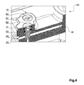
Fig. 4 an embodiment of an inventive hydraulic door closer, -
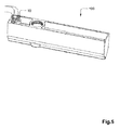
Fig. 5 the embodiment ofFig. 4 in a further view, -
Fig. 6 an embodiment of an inventive valve cap and -
Fig. 7 the embodiment ofFig. 6 in another view. -
Fig. 1 to 3 show a first embodiment of aninventive valve device 10. The valve device comprises within a housing avalve entrance 20 as well as avalve exit 30. The two openings of thevalve entrance 20 and thevalve exit 30 are in fluid communication with each other via avalve channel 40. Hydraulic fluid can flow into thevalve entrance 20 passing avalve body 50 which is offering a passage area around thevalve body 50 and flow through thevalve channel 40 out of thevalve exit 30. - According to
Fig. 1 , thevalve body 50 can be moved upwards and downwards along a movement axis which is correlated with athread axis 52a of anadjustment thread 52. The movement of adjusting valve positions of thevalve body 50 is carried out by rotation of thevalve body 50. A tool head can be used to correlate with anadjustment interface 58 to carry out the rotation of thevalve body 50 relative to thethread axis 52a. After thevalve body 50 has been positioned in the respective valve position, for example in a first valve position P1 according toFig. 2 , this position will be secured. To secure that position avalve cap 60 is used and also rotated around athread axis 62a of a securingthread 62. Thethread axis 62a of the securingthread 62 is common and parallel with thethread axis 52a of theadjustment thread 52. The rotation of thevalve cap 60 is carried out until thecontact surface 62 of the valve cap contacts thecounter contact surface 54 of the valve body. - Due to the fact that the securing
thread 62 has a contrary thread direction that the adjustment thread, a securing functionality is given. - During use of a respective hydraulic door closer 100, fluid of the hydraulic fluid can flow through the
valve channel 40. This can lead to an increase of flow and fluid pressure inside of the valve channel tending thevalve body 50 to move upwards inFig. 2 . The upward movement could take place by a forced rotation of thevalve body 50 around thethread axis 52a of theadjustment thread 52. Due to the fact that thecounter contact surface 54 of thevalve body 50 is in contact with acontact surface 64 of thevalve cap 60, via frictional forces this rotational movement ofvalve body 50 would be transferred to a rotational movement of thevalve cap 60 in the same direction. Due to the fact that the thread direction of the securingthread 62 is contrary to the thread direction of theadjustment thread 52, this leads to a contrary directed downward force of the movement by the securingthread 62 of thevalve cap 60. Thereby, even with increased fluid pressure within thevalve channel 60, the first valve position P1 or, for example accordingFig. 3 the valve position P2 according this situation is secured by therespective valve cap 60. - To achieve even further frictional forces between the two elements, namely the
valve cap 60 and thevalve body 50, they comprise further contact surfaces, namely thecentration surface 66 of thevalve cap 60 and thecounter centration surface 56 of thevalve body 50. Beside a centration functionality during the method of securing thevalve body 50, this leads to a higher contact surface overall to increase frictional forces between the two elements and thereby increasing the securing situation. -
Fig. 4 and5 disclose further embodiment of thevalve devices 10, which are here positioned in an inventivehydraulic door closer 100. This door closer 100 comprises a damping functionality for the movement in the opening as well as in the closing direction. Due to the fact that twoseparate valve devices 10 according to the present invention are used the two different movements can be configured with different variations of the damping effect by giving different valve positions P1 and P2 for the twoseparate valve devices 10. -
Fig. 6 and 7 show an embodiment of aninventive valve cap 60. As it can be seen here, thevalve cap 60 comprises anadjustment opening 68, opening a passage way to arespective adjustment interface 58 of the valve body. Moreover, it can be seen that the securingthread 62 is an outer thread. Inside of thevalve cap 60 the two different orientated surfaces, namely thecontact surface 64 as well as thecentration surface 66 can be seen. From the outside view according toFig. 6 , a handlinginterface 61 can be seen, which correlates with the head of a screw driver to carry out the securing movement, namely the rotation relative to the securing axis. - Aforesaid discussion of the different embodiments is only carried out by the way of example and does not limit the scope of protection of the present invention.
-
- 10
- valve device
- 20
- valve entrance
- 30
- valve exit
- 40
- valve channel
- 50
- valve body
- 52
- adjustment thread
- 52a
- thread axis
- 54
- counter contact surface
- 56
- counter centration surface
- 58
- adjustment interface
- 60
- valve cap
- 61
- handling interface
- 62
- securing thread
- 62a
- thread axis
- 64
- contact surface
- 66
- centration surface
- 68
- adjustment opening
- 100
- hydraulic door closer
- P1
- first valve position
- P2
- second valve position
Claims (10)
- Valve device (10) for a hydraulic door closer (100), comprising a valve entrance (20), a valve exit (30) which is in fluid communication with the valve entrance (20) via a valve channel (40), further comprising a valve body (50) with an adjustment thread (52) which is arranged within the valve channel (40) moveable by the adjustment thread (52) between a first valve position (P1) with a first passage area and at least a second valve position (P2) with a second passage area, characterized in that a valve cap (60) is arranged with a contact surface (64) contacting a counter contact surface (54) of the valve body (50), wherein the valve cap (60) comprises a securing thread (62) with contrary thread direction compared to the adjustment thread (52) for counter bearing of the valve body (50).
- Valve device (10) according to claim 1, characterized in that the adjustment thread (52) and the securing thread (62) comprise the same or at least the same thread pitches with contrary thread directions, in particular standard thread pitches.
- Valve device (10) according to any of the preceding claims, characterized in that the adjustment thread (52) and the securing thread (62) comprise parallel or at least parallel oriented thread axes (52a, 62a), in particular a common thread axis (52a, 62a).
- Valve device (10) according to any of the preceding claims, characterized in that the valve cap (60) comprises a centration surface (66), with a different extension compared to the contact surface (64), contacting a counter centration surface (56) of the valve body (50).
- Valve device (10) according to any of the preceding claims, characterized in that the valve cap (60) comprises an adjustment opening (68), opening a passage way to an adjustment interface (58) of the valve body (50).
- Valve device (10) according to any of the preceding claims, characterized in that the valve cap (60) comprises a handling interface (61) for turning the valve cap (60) relative to a thread axis (62a) of the securing thread (62).
- Valve cap (60) for use in a valve device (10) according to any of the preceding claims, characterized in that it comprises a contact surface (64) for contacting the counter contact surface (54) of a valve body (50) of the valve device (10), further comprising a securing thread (62) with a contrary thread direction compared to an adjustment thread (52) of the valve body (50) for counter bearing the valve body (50).
- Hydraulic door closer (100) comprising a fluid system for damping the closing movement and/or the opening movement of a door, characterized in that the fluid system comprises at least one valve device (10) with the features of any of claims 1 to 6.
- Hydraulic door closer (100) according to claim 8, characterized in that the fluid system comprises two valve devices (10) with the features of any of claims 1 to 6, one valve device (10) for the opening movement of the door and one valve device (10) for the closing movement of the door.
- Method of securing a valve position (P1, P2) of a valve body (50) of a valve device (10), in particular with the features of any of claims 1 to 6, comprising the following steps:- Turning the valve body (50) around a thread axis (52a) of an adjustment thread (52) into a first valve position (P1),- Turning a valve cap (60) around the thread axis (62a) of a securing thread (62) until a contact surface (64) of the valve cap (60) contacts a counter contact surface (54) of the valve body (50).
Applications Claiming Priority (1)
| Application Number | Priority Date | Filing Date | Title |
|---|---|---|---|
| DE102014101416.2A DE102014101416A1 (en) | 2014-02-05 | 2014-02-05 | Valve device for a hydraulic door closer |
Publications (2)
| Publication Number | Publication Date |
|---|---|
| EP2905407A1 true EP2905407A1 (en) | 2015-08-12 |
| EP2905407B1 EP2905407B1 (en) | 2016-11-16 |
Family
ID=52394926
Family Applications (1)
| Application Number | Title | Priority Date | Filing Date |
|---|---|---|---|
| EP15151755.4A Active EP2905407B1 (en) | 2014-02-05 | 2015-01-20 | Hydraulic door closer with a valve device |
Country Status (3)
| Country | Link |
|---|---|
| EP (1) | EP2905407B1 (en) |
| CN (1) | CN104819305B (en) |
| DE (1) | DE102014101416A1 (en) |
Cited By (3)
| Publication number | Priority date | Publication date | Assignee | Title |
|---|---|---|---|---|
| GB2570703A (en) * | 2018-02-05 | 2019-08-07 | Bae Systems Plc | Temporary valve cap |
| US10697429B2 (en) | 2016-01-29 | 2020-06-30 | Mitsubishi Heavy Industries, Ltd. | Controller for wind turbine, wind turbine, program for rotor turning, and method of rotor turning for wind turbine |
| CN114212389A (en) * | 2021-11-26 | 2022-03-22 | 山西江淮重工有限责任公司 | Telescopic pumping and inflating device and sealed storage container |
Families Citing this family (4)
| Publication number | Priority date | Publication date | Assignee | Title |
|---|---|---|---|---|
| DE102017211032B4 (en) | 2017-06-29 | 2024-05-08 | Geze Gmbh | Control valve |
| CN109099177A (en) * | 2018-09-07 | 2018-12-28 | 上海东铁五金有限公司 | A kind of regulating valve and the floor spring including it |
| US10961760B2 (en) * | 2019-02-08 | 2021-03-30 | Schlage Lock Company Llc | Door closer with backout prevention |
| US11732516B2 (en) * | 2021-07-12 | 2023-08-22 | Schlage Lock Company Llc | Door closer adjustment with backout discouragement |
Citations (4)
| Publication number | Priority date | Publication date | Assignee | Title |
|---|---|---|---|---|
| GB647808A (en) * | 1948-05-12 | 1950-12-20 | Arthur Richie Kearney | Improvements in or relating to check valves |
| US2586135A (en) * | 1949-10-15 | 1952-02-19 | Ben H Woodruff | Door closer |
| EP1491801A1 (en) * | 2003-06-26 | 2004-12-29 | Pacific Industrial Co., Ltd. | Valve plug and valve provided therewith |
| DE202007004104U1 (en) | 2007-03-16 | 2007-05-24 | Dorma Gmbh + Co. Kg | Regulating valve for hydraulic door closer has anti-rotation lock on body formed by groove on thread and holding elastic element to eliminate play |
Family Cites Families (3)
| Publication number | Priority date | Publication date | Assignee | Title |
|---|---|---|---|---|
| CN2483565Y (en) * | 2001-05-18 | 2002-03-27 | 黄俊杰 | Air-conditioning control valve |
| DE10228871A1 (en) * | 2002-06-27 | 2004-01-15 | Dorma Gmbh + Co. Kg | spool valve |
| CN101922496A (en) * | 2009-09-03 | 2010-12-22 | 张元金 | Bolt and bolt connecting structure thereof |
-
2014
- 2014-02-05 DE DE102014101416.2A patent/DE102014101416A1/en active Pending
-
2015
- 2015-01-20 EP EP15151755.4A patent/EP2905407B1/en active Active
- 2015-02-03 CN CN201510056017.3A patent/CN104819305B/en active Active
Patent Citations (4)
| Publication number | Priority date | Publication date | Assignee | Title |
|---|---|---|---|---|
| GB647808A (en) * | 1948-05-12 | 1950-12-20 | Arthur Richie Kearney | Improvements in or relating to check valves |
| US2586135A (en) * | 1949-10-15 | 1952-02-19 | Ben H Woodruff | Door closer |
| EP1491801A1 (en) * | 2003-06-26 | 2004-12-29 | Pacific Industrial Co., Ltd. | Valve plug and valve provided therewith |
| DE202007004104U1 (en) | 2007-03-16 | 2007-05-24 | Dorma Gmbh + Co. Kg | Regulating valve for hydraulic door closer has anti-rotation lock on body formed by groove on thread and holding elastic element to eliminate play |
Cited By (4)
| Publication number | Priority date | Publication date | Assignee | Title |
|---|---|---|---|---|
| US10697429B2 (en) | 2016-01-29 | 2020-06-30 | Mitsubishi Heavy Industries, Ltd. | Controller for wind turbine, wind turbine, program for rotor turning, and method of rotor turning for wind turbine |
| GB2570703A (en) * | 2018-02-05 | 2019-08-07 | Bae Systems Plc | Temporary valve cap |
| GB2570703B (en) * | 2018-02-05 | 2022-07-06 | Bae Systems Plc | Temporary valve cover |
| CN114212389A (en) * | 2021-11-26 | 2022-03-22 | 山西江淮重工有限责任公司 | Telescopic pumping and inflating device and sealed storage container |
Also Published As
| Publication number | Publication date |
|---|---|
| DE102014101416A1 (en) | 2015-08-06 |
| EP2905407B1 (en) | 2016-11-16 |
| CN104819305A (en) | 2015-08-05 |
| CN104819305B (en) | 2019-06-25 |
Similar Documents
| Publication | Publication Date | Title |
|---|---|---|
| EP2905407B1 (en) | Hydraulic door closer with a valve device | |
| KR101802027B1 (en) | Valve device and pipe coupling having the valve device | |
| EP2466058A1 (en) | An inflow assembly | |
| WO2016059419A3 (en) | Microfluidic chip | |
| WO2017003733A1 (en) | Integrated check-relief valve | |
| WO2014147327A8 (en) | Method for drilling an ophthalmic lens in a helical trajectory and associated drilling device | |
| WO2016019154A3 (en) | Downhole tool with counting mechanism | |
| EP2631515A3 (en) | Plug valve with a spring biased plug | |
| JP6774786B2 (en) | Rotary damper | |
| EP2882928B1 (en) | Rotational shear valve | |
| EP3203015A3 (en) | Spray nozzle for underground roof support | |
| EP3134667B1 (en) | Fluid control devices including self-healing materials and related methods | |
| GB2572094A (en) | Fully electric tool for continous downhole flow control | |
| WO2015143117A3 (en) | Selector valve for high pressure hydrocarbon production operations | |
| GB2575604A (en) | Magnetic flow valve for borehole use | |
| JP2012506978A5 (en) | Valve and packing follower and jet protection mechanism for use therein | |
| CN112901801A (en) | Electronic expansion valve | |
| EP2436960A3 (en) | Sealing bushing assembly and hydraulic device | |
| GB202001399D0 (en) | Centrifugally motivated fluidic systems, devices and methods | |
| GB2563172A (en) | Improvement to force multiplyer used to actuate a ball valve | |
| EP4165388A4 (en) | Microfluidic devices, systems, and methods | |
| WO2014110523A3 (en) | Method and apparatus for sealing tubulars | |
| EP2549156B1 (en) | Valve top for fittings | |
| KR101947409B1 (en) | Application Device | |
| WO2016028236A3 (en) | Methods, systems, and devices for controlling operation of a valve |
Legal Events
| Date | Code | Title | Description |
|---|---|---|---|
| PUAI | Public reference made under article 153(3) epc to a published international application that has entered the european phase |
Free format text: ORIGINAL CODE: 0009012 |
|
| AK | Designated contracting states |
Kind code of ref document: A1 Designated state(s): AL AT BE BG CH CY CZ DE DK EE ES FI FR GB GR HR HU IE IS IT LI LT LU LV MC MK MT NL NO PL PT RO RS SE SI SK SM TR |
|
| AX | Request for extension of the european patent |
Extension state: BA ME |
|
| 17P | Request for examination filed |
Effective date: 20160121 |
|
| RBV | Designated contracting states (corrected) |
Designated state(s): AL AT BE BG CH CY CZ DE DK EE ES FI FR GB GR HR HU IE IS IT LI LT LU LV MC MK MT NL NO PL PT RO RS SE SI SK SM TR |
|
| GRAP | Despatch of communication of intention to grant a patent |
Free format text: ORIGINAL CODE: EPIDOSNIGR1 |
|
| RIC1 | Information provided on ipc code assigned before grant |
Ipc: F16K 1/50 20060101ALI20160509BHEP Ipc: E05F 3/12 20060101AFI20160509BHEP Ipc: F16K 35/00 20060101ALI20160509BHEP |
|
| INTG | Intention to grant announced |
Effective date: 20160531 |
|
| GRAS | Grant fee paid |
Free format text: ORIGINAL CODE: EPIDOSNIGR3 |
|
| GRAA | (expected) grant |
Free format text: ORIGINAL CODE: 0009210 |
|
| AK | Designated contracting states |
Kind code of ref document: B1 Designated state(s): AL AT BE BG CH CY CZ DE DK EE ES FI FR GB GR HR HU IE IS IT LI LT LU LV MC MK MT NL NO PL PT RO RS SE SI SK SM TR |
|
| REG | Reference to a national code |
Ref country code: GB Ref legal event code: FG4D |
|
| REG | Reference to a national code |
Ref country code: CH Ref legal event code: EP |
|
| REG | Reference to a national code |
Ref country code: IE Ref legal event code: FG4D |
|
| REG | Reference to a national code |
Ref country code: AT Ref legal event code: REF Ref document number: 846126 Country of ref document: AT Kind code of ref document: T Effective date: 20161215 |
|
| REG | Reference to a national code |
Ref country code: DE Ref legal event code: R096 Ref document number: 602015000697 Country of ref document: DE |
|
| REG | Reference to a national code |
Ref country code: DE Ref legal event code: R096 Ref document number: 602015000697 Country of ref document: DE |
|
| PG25 | Lapsed in a contracting state [announced via postgrant information from national office to epo] |
Ref country code: LV Free format text: LAPSE BECAUSE OF FAILURE TO SUBMIT A TRANSLATION OF THE DESCRIPTION OR TO PAY THE FEE WITHIN THE PRESCRIBED TIME-LIMIT Effective date: 20161116 |
|
| REG | Reference to a national code |
Ref country code: NL Ref legal event code: MP Effective date: 20161116 |
|
| REG | Reference to a national code |
Ref country code: LT Ref legal event code: MG4D |
|
| REG | Reference to a national code |
Ref country code: AT Ref legal event code: MK05 Ref document number: 846126 Country of ref document: AT Kind code of ref document: T Effective date: 20161116 |
|
| PG25 | Lapsed in a contracting state [announced via postgrant information from national office to epo] |
Ref country code: SE Free format text: LAPSE BECAUSE OF FAILURE TO SUBMIT A TRANSLATION OF THE DESCRIPTION OR TO PAY THE FEE WITHIN THE PRESCRIBED TIME-LIMIT Effective date: 20161116 Ref country code: LT Free format text: LAPSE BECAUSE OF FAILURE TO SUBMIT A TRANSLATION OF THE DESCRIPTION OR TO PAY THE FEE WITHIN THE PRESCRIBED TIME-LIMIT Effective date: 20161116 Ref country code: NL Free format text: LAPSE BECAUSE OF FAILURE TO SUBMIT A TRANSLATION OF THE DESCRIPTION OR TO PAY THE FEE WITHIN THE PRESCRIBED TIME-LIMIT Effective date: 20161116 Ref country code: NO Free format text: LAPSE BECAUSE OF FAILURE TO SUBMIT A TRANSLATION OF THE DESCRIPTION OR TO PAY THE FEE WITHIN THE PRESCRIBED TIME-LIMIT Effective date: 20170216 Ref country code: GR Free format text: LAPSE BECAUSE OF FAILURE TO SUBMIT A TRANSLATION OF THE DESCRIPTION OR TO PAY THE FEE WITHIN THE PRESCRIBED TIME-LIMIT Effective date: 20170217 |
|
| REG | Reference to a national code |
Ref country code: DE Ref legal event code: R082 Ref document number: 602015000697 Country of ref document: DE Representative=s name: BALDER IP LAW, S.L., ES Ref country code: DE Ref legal event code: R081 Ref document number: 602015000697 Country of ref document: DE Owner name: DORMAKABA DEUTSCHLAND GMBH, DE Free format text: FORMER OWNER: DORMA DEUTSCHLAND GMBH, 58256 ENNEPETAL, DE |
|
| PG25 | Lapsed in a contracting state [announced via postgrant information from national office to epo] |
Ref country code: PL Free format text: LAPSE BECAUSE OF FAILURE TO SUBMIT A TRANSLATION OF THE DESCRIPTION OR TO PAY THE FEE WITHIN THE PRESCRIBED TIME-LIMIT Effective date: 20161116 Ref country code: BE Free format text: LAPSE BECAUSE OF NON-PAYMENT OF DUE FEES Effective date: 20170131 Ref country code: AT Free format text: LAPSE BECAUSE OF FAILURE TO SUBMIT A TRANSLATION OF THE DESCRIPTION OR TO PAY THE FEE WITHIN THE PRESCRIBED TIME-LIMIT Effective date: 20161116 Ref country code: HR Free format text: LAPSE BECAUSE OF FAILURE TO SUBMIT A TRANSLATION OF THE DESCRIPTION OR TO PAY THE FEE WITHIN THE PRESCRIBED TIME-LIMIT Effective date: 20161116 Ref country code: ES Free format text: LAPSE BECAUSE OF FAILURE TO SUBMIT A TRANSLATION OF THE DESCRIPTION OR TO PAY THE FEE WITHIN THE PRESCRIBED TIME-LIMIT Effective date: 20161116 Ref country code: RS Free format text: LAPSE BECAUSE OF FAILURE TO SUBMIT A TRANSLATION OF THE DESCRIPTION OR TO PAY THE FEE WITHIN THE PRESCRIBED TIME-LIMIT Effective date: 20161116 Ref country code: PT Free format text: LAPSE BECAUSE OF FAILURE TO SUBMIT A TRANSLATION OF THE DESCRIPTION OR TO PAY THE FEE WITHIN THE PRESCRIBED TIME-LIMIT Effective date: 20170316 Ref country code: FI Free format text: LAPSE BECAUSE OF FAILURE TO SUBMIT A TRANSLATION OF THE DESCRIPTION OR TO PAY THE FEE WITHIN THE PRESCRIBED TIME-LIMIT Effective date: 20161116 |
|
| PG25 | Lapsed in a contracting state [announced via postgrant information from national office to epo] |
Ref country code: CZ Free format text: LAPSE BECAUSE OF FAILURE TO SUBMIT A TRANSLATION OF THE DESCRIPTION OR TO PAY THE FEE WITHIN THE PRESCRIBED TIME-LIMIT Effective date: 20161116 Ref country code: EE Free format text: LAPSE BECAUSE OF FAILURE TO SUBMIT A TRANSLATION OF THE DESCRIPTION OR TO PAY THE FEE WITHIN THE PRESCRIBED TIME-LIMIT Effective date: 20161116 Ref country code: SK Free format text: LAPSE BECAUSE OF FAILURE TO SUBMIT A TRANSLATION OF THE DESCRIPTION OR TO PAY THE FEE WITHIN THE PRESCRIBED TIME-LIMIT Effective date: 20161116 Ref country code: RO Free format text: LAPSE BECAUSE OF FAILURE TO SUBMIT A TRANSLATION OF THE DESCRIPTION OR TO PAY THE FEE WITHIN THE PRESCRIBED TIME-LIMIT Effective date: 20161116 Ref country code: DK Free format text: LAPSE BECAUSE OF FAILURE TO SUBMIT A TRANSLATION OF THE DESCRIPTION OR TO PAY THE FEE WITHIN THE PRESCRIBED TIME-LIMIT Effective date: 20161116 |
|
| REG | Reference to a national code |
Ref country code: DE Ref legal event code: R097 Ref document number: 602015000697 Country of ref document: DE |
|
| PG25 | Lapsed in a contracting state [announced via postgrant information from national office to epo] |
Ref country code: IT Free format text: LAPSE BECAUSE OF FAILURE TO SUBMIT A TRANSLATION OF THE DESCRIPTION OR TO PAY THE FEE WITHIN THE PRESCRIBED TIME-LIMIT Effective date: 20161116 Ref country code: SM Free format text: LAPSE BECAUSE OF FAILURE TO SUBMIT A TRANSLATION OF THE DESCRIPTION OR TO PAY THE FEE WITHIN THE PRESCRIBED TIME-LIMIT Effective date: 20161116 Ref country code: BE Free format text: LAPSE BECAUSE OF FAILURE TO SUBMIT A TRANSLATION OF THE DESCRIPTION OR TO PAY THE FEE WITHIN THE PRESCRIBED TIME-LIMIT Effective date: 20161116 Ref country code: BG Free format text: LAPSE BECAUSE OF FAILURE TO SUBMIT A TRANSLATION OF THE DESCRIPTION OR TO PAY THE FEE WITHIN THE PRESCRIBED TIME-LIMIT Effective date: 20170216 |
|
| PLBE | No opposition filed within time limit |
Free format text: ORIGINAL CODE: 0009261 |
|
| STAA | Information on the status of an ep patent application or granted ep patent |
Free format text: STATUS: NO OPPOSITION FILED WITHIN TIME LIMIT |
|
| PG25 | Lapsed in a contracting state [announced via postgrant information from national office to epo] |
Ref country code: MC Free format text: LAPSE BECAUSE OF FAILURE TO SUBMIT A TRANSLATION OF THE DESCRIPTION OR TO PAY THE FEE WITHIN THE PRESCRIBED TIME-LIMIT Effective date: 20161116 |
|
| 26N | No opposition filed |
Effective date: 20170817 |
|
| REG | Reference to a national code |
Ref country code: FR Ref legal event code: ST Effective date: 20170929 |
|
| PG25 | Lapsed in a contracting state [announced via postgrant information from national office to epo] |
Ref country code: FR Free format text: LAPSE BECAUSE OF NON-PAYMENT OF DUE FEES Effective date: 20170131 |
|
| REG | Reference to a national code |
Ref country code: IE Ref legal event code: MM4A |
|
| PG25 | Lapsed in a contracting state [announced via postgrant information from national office to epo] |
Ref country code: LU Free format text: LAPSE BECAUSE OF NON-PAYMENT OF DUE FEES Effective date: 20170120 Ref country code: SI Free format text: LAPSE BECAUSE OF FAILURE TO SUBMIT A TRANSLATION OF THE DESCRIPTION OR TO PAY THE FEE WITHIN THE PRESCRIBED TIME-LIMIT Effective date: 20161116 |
|
| PG25 | Lapsed in a contracting state [announced via postgrant information from national office to epo] |
Ref country code: IE Free format text: LAPSE BECAUSE OF NON-PAYMENT OF DUE FEES Effective date: 20170120 |
|
| REG | Reference to a national code |
Ref country code: CH Ref legal event code: PL |
|
| PG25 | Lapsed in a contracting state [announced via postgrant information from national office to epo] |
Ref country code: MT Free format text: LAPSE BECAUSE OF NON-PAYMENT OF DUE FEES Effective date: 20170120 |
|
| PG25 | Lapsed in a contracting state [announced via postgrant information from national office to epo] |
Ref country code: LI Free format text: LAPSE BECAUSE OF NON-PAYMENT OF DUE FEES Effective date: 20180131 Ref country code: CH Free format text: LAPSE BECAUSE OF NON-PAYMENT OF DUE FEES Effective date: 20180131 |
|
| PG25 | Lapsed in a contracting state [announced via postgrant information from national office to epo] |
Ref country code: HU Free format text: LAPSE BECAUSE OF FAILURE TO SUBMIT A TRANSLATION OF THE DESCRIPTION OR TO PAY THE FEE WITHIN THE PRESCRIBED TIME-LIMIT; INVALID AB INITIO Effective date: 20150120 |
|
| GBPC | Gb: european patent ceased through non-payment of renewal fee |
Effective date: 20190120 |
|
| PG25 | Lapsed in a contracting state [announced via postgrant information from national office to epo] |
Ref country code: CY Free format text: LAPSE BECAUSE OF FAILURE TO SUBMIT A TRANSLATION OF THE DESCRIPTION OR TO PAY THE FEE WITHIN THE PRESCRIBED TIME-LIMIT Effective date: 20161116 |
|
| PG25 | Lapsed in a contracting state [announced via postgrant information from national office to epo] |
Ref country code: MK Free format text: LAPSE BECAUSE OF FAILURE TO SUBMIT A TRANSLATION OF THE DESCRIPTION OR TO PAY THE FEE WITHIN THE PRESCRIBED TIME-LIMIT Effective date: 20161116 |
|
| PG25 | Lapsed in a contracting state [announced via postgrant information from national office to epo] |
Ref country code: GB Free format text: LAPSE BECAUSE OF NON-PAYMENT OF DUE FEES Effective date: 20190120 |
|
| PG25 | Lapsed in a contracting state [announced via postgrant information from national office to epo] |
Ref country code: TR Free format text: LAPSE BECAUSE OF FAILURE TO SUBMIT A TRANSLATION OF THE DESCRIPTION OR TO PAY THE FEE WITHIN THE PRESCRIBED TIME-LIMIT Effective date: 20161116 |
|
| PG25 | Lapsed in a contracting state [announced via postgrant information from national office to epo] |
Ref country code: AL Free format text: LAPSE BECAUSE OF FAILURE TO SUBMIT A TRANSLATION OF THE DESCRIPTION OR TO PAY THE FEE WITHIN THE PRESCRIBED TIME-LIMIT Effective date: 20161116 Ref country code: IS Free format text: LAPSE BECAUSE OF FAILURE TO SUBMIT A TRANSLATION OF THE DESCRIPTION OR TO PAY THE FEE WITHIN THE PRESCRIBED TIME-LIMIT Effective date: 20170316 |
|
| PGFP | Annual fee paid to national office [announced via postgrant information from national office to epo] |
Ref country code: DE Payment date: 20250121 Year of fee payment: 11 |