EP2905212A1 - Hub system and vehicle - Google Patents
Hub system and vehicle Download PDFInfo
- Publication number
- EP2905212A1 EP2905212A1 EP15154498.8A EP15154498A EP2905212A1 EP 2905212 A1 EP2905212 A1 EP 2905212A1 EP 15154498 A EP15154498 A EP 15154498A EP 2905212 A1 EP2905212 A1 EP 2905212A1
- Authority
- EP
- European Patent Office
- Prior art keywords
- hub
- vehicle
- driving member
- shell
- hub shell
- Prior art date
- Legal status (The legal status is an assumption and is not a legal conclusion. Google has not performed a legal analysis and makes no representation as to the accuracy of the status listed.)
- Granted
Links
Images


Classifications
-
- B—PERFORMING OPERATIONS; TRANSPORTING
- B60—VEHICLES IN GENERAL
- B60B—VEHICLE WHEELS; CASTORS; AXLES FOR WHEELS OR CASTORS; INCREASING WHEEL ADHESION
- B60B35/00—Axle units; Parts thereof ; Arrangements for lubrication of axles
- B60B35/12—Torque-transmitting axles
-
- B—PERFORMING OPERATIONS; TRANSPORTING
- B60—VEHICLES IN GENERAL
- B60B—VEHICLE WHEELS; CASTORS; AXLES FOR WHEELS OR CASTORS; INCREASING WHEEL ADHESION
- B60B27/00—Hubs
- B60B27/0047—Hubs characterised by functional integration of other elements
- B60B27/0057—Hubs characterised by functional integration of other elements the element being a brake drum
-
- B—PERFORMING OPERATIONS; TRANSPORTING
- B60—VEHICLES IN GENERAL
- B60B—VEHICLE WHEELS; CASTORS; AXLES FOR WHEELS OR CASTORS; INCREASING WHEEL ADHESION
- B60B27/00—Hubs
- B60B27/02—Hubs adapted to be rotatably arranged on axle
- B60B27/023—Hubs adapted to be rotatably arranged on axle specially adapted for bicycles
-
- B—PERFORMING OPERATIONS; TRANSPORTING
- B62—LAND VEHICLES FOR TRAVELLING OTHERWISE THAN ON RAILS
- B62L—BRAKES SPECIALLY ADAPTED FOR CYCLES
- B62L5/00—Brakes, or actuating mechanisms therefor, controlled by back-pedalling
- B62L5/02—Brakes, or actuating mechanisms therefor, controlled by back-pedalling the brakes being actuated through coacting coaxial cones located in the rear wheel hub
-
- F—MECHANICAL ENGINEERING; LIGHTING; HEATING; WEAPONS; BLASTING
- F16—ENGINEERING ELEMENTS AND UNITS; GENERAL MEASURES FOR PRODUCING AND MAINTAINING EFFECTIVE FUNCTIONING OF MACHINES OR INSTALLATIONS; THERMAL INSULATION IN GENERAL
- F16D—COUPLINGS FOR TRANSMITTING ROTATION; CLUTCHES; BRAKES
- F16D13/00—Friction clutches
- F16D13/22—Friction clutches with axially-movable clutching members
- F16D13/24—Friction clutches with axially-movable clutching members with conical friction surfaces cone clutches
- F16D13/26—Friction clutches with axially-movable clutching members with conical friction surfaces cone clutches in which the or each axially-movable member is pressed exclusively against an axially-located member
-
- F—MECHANICAL ENGINEERING; LIGHTING; HEATING; WEAPONS; BLASTING
- F16—ENGINEERING ELEMENTS AND UNITS; GENERAL MEASURES FOR PRODUCING AND MAINTAINING EFFECTIVE FUNCTIONING OF MACHINES OR INSTALLATIONS; THERMAL INSULATION IN GENERAL
- F16D—COUPLINGS FOR TRANSMITTING ROTATION; CLUTCHES; BRAKES
- F16D41/00—Freewheels or freewheel clutches
- F16D41/24—Freewheels or freewheel clutches specially adapted for cycles
-
- F—MECHANICAL ENGINEERING; LIGHTING; HEATING; WEAPONS; BLASTING
- F16—ENGINEERING ELEMENTS AND UNITS; GENERAL MEASURES FOR PRODUCING AND MAINTAINING EFFECTIVE FUNCTIONING OF MACHINES OR INSTALLATIONS; THERMAL INSULATION IN GENERAL
- F16D—COUPLINGS FOR TRANSMITTING ROTATION; CLUTCHES; BRAKES
- F16D67/00—Combinations of couplings and brakes; Combinations of clutches and brakes
- F16D67/02—Clutch-brake combinations
-
- B—PERFORMING OPERATIONS; TRANSPORTING
- B60—VEHICLES IN GENERAL
- B60B—VEHICLE WHEELS; CASTORS; AXLES FOR WHEELS OR CASTORS; INCREASING WHEEL ADHESION
- B60B27/00—Hubs
- B60B27/02—Hubs adapted to be rotatably arranged on axle
- B60B27/04—Hubs adapted to be rotatably arranged on axle housing driving means, e.g. sprockets
- B60B27/047—Hubs adapted to be rotatably arranged on axle housing driving means, e.g. sprockets comprising a freewheel mechanisms
-
- B—PERFORMING OPERATIONS; TRANSPORTING
- B62—LAND VEHICLES FOR TRAVELLING OTHERWISE THAN ON RAILS
- B62K—CYCLES; CYCLE FRAMES; CYCLE STEERING DEVICES; RIDER-OPERATED TERMINAL CONTROLS SPECIALLY ADAPTED FOR CYCLES; CYCLE AXLE SUSPENSIONS; CYCLE SIDECARS, FORECARS, OR THE LIKE
- B62K5/00—Cycles with handlebars, equipped with three or more main road wheels
- B62K5/02—Tricycles
-
- B—PERFORMING OPERATIONS; TRANSPORTING
- B62—LAND VEHICLES FOR TRAVELLING OTHERWISE THAN ON RAILS
- B62M—RIDER PROPULSION OF WHEELED VEHICLES OR SLEDGES; POWERED PROPULSION OF SLEDGES OR SINGLE-TRACK CYCLES; TRANSMISSIONS SPECIALLY ADAPTED FOR SUCH VEHICLES
- B62M9/00—Transmissions characterised by use of an endless chain, belt, or the like
- B62M9/02—Transmissions characterised by use of an endless chain, belt, or the like of unchangeable ratio
-
- F—MECHANICAL ENGINEERING; LIGHTING; HEATING; WEAPONS; BLASTING
- F16—ENGINEERING ELEMENTS AND UNITS; GENERAL MEASURES FOR PRODUCING AND MAINTAINING EFFECTIVE FUNCTIONING OF MACHINES OR INSTALLATIONS; THERMAL INSULATION IN GENERAL
- F16D—COUPLINGS FOR TRANSMITTING ROTATION; CLUTCHES; BRAKES
- F16D23/00—Details of mechanically-actuated clutches not specific for one distinct type
- F16D23/12—Mechanical clutch-actuating mechanisms arranged outside the clutch as such
- F16D2023/123—Clutch actuation by cams, ramps or ball-screw mechanisms
Definitions
- the invention relates to a hub system for a vehicle, such as a chain driven vehicle, for example a go-kart for a child.
- Such hub systems for instance conventional bike hub systems, are often provided with a coaster brake arrangement.
- hub systems with a coaster brake arrangement which comprise: a hub shaft; a driving member being rotatably mounted with respect to the hub shaft; a hub shell being rotatably mounted with respect to the hub shaft; a brake shoe arranged for engaging the hub shell such as to be coupled with said hub shell temporarily; a brake anchor arranged to be fixedly attached to a frame of a vehicle; and a coupling element arranged for enabling coupling between the driving member and the hub shell in a first position of said coupling element, and for enabling coupling between the brake anchor and the hub shell in a second position of the coupling element.
- BFR Brake, Forward and Reverse.
- Said BFR hub system allows a driver to drive forwards by pedalling forwards, to coast with the pedals remaining static when the vehicle is already rolling forwards, to brake by pedalling backwards slightly thereby activating an integrated coaster brake which comprises the brake shoe, and - due to the freewheel device - to drive backwards by pedalling further backwards after having braked.
- Vehicles such as go-karts, provided with said BFR hub system normally have a driving axis rotatably arranged in a vehicle frame, said driving axis normally being provided with pedals and a driving chain-wheel, which generally is coupled with a driven sprocket-wheel by means of a drive chain.
- said driven chain-wheel is positioned around the hub shaft of the hub system, which hub shaft is fixed in rotational direction with respect to the vehicle frame, at a first lateral side of a hub shell of the system.
- the brake anchor is fixedly attached to the frame.
- said driven sprocket-wheel is coupled to the driving member of the hub system, thereby enabling that rotational motion of the pedals and corresponding rotational motion of the driving member can make the hub shell to rotate forwards in order to drive forwards, can brake the hub shell, and can make the hub shell to rotate backwards subsequently in order to drive backwards.
- a second driving chain-wheel is fixedly connected to said hub shell.
- said second driving chain-wheel is coupled with a second driven sprocket-wheel fixedly provided on a driven axis for driving at least one wheel, for example a left rear wheel, of the vehicle.
- An advantage of a conventional BFR hub system over a normal coaster-brake hub system can lie in that such BFR hub system cannot only allow driving by pedalling forwards, coasting and braking, but can also allow a driver to drive rearwards after having braked.
- disadvantages of a conventional BFR hub system may lie in that vehicles provided with such a hub system are normally of relatively complex design, e.g. due to the two separate drive chains. Further, the assembly and/or maintenance of the hub system and/or the vehicle, and/or (re-)adjustment of parts can be relatively difficult, time-consuming, error-prone and/or labour-intensive.
- An object of the present invention is to provide an alternative hub system and/or an alternative vehicle, especially a go-kart and/or a chain driven or belt vehicle, preferably for a child.
- the invention aims at providing a hub system, wherein at least one of the disadvantages of a conventional hub system is counteracted or advantages there above are obtained.
- the invention aims at providing a hub system which is arranged such that a vehicle provided with such hub system can be of relative simple design.
- the invention aims at providing a hub system which can enable that a vehicle provided therewith can allow driving forwards by pedalling forwards, can allow coasting, can allow braking, and can also allow driving rearwards after a user has braked, preferably without said vehicle having a relative complex design and/or without said vehicle being provided with two separate drive chains and/or an additional axis.
- the present invention provides for a hub system which comprises: a hub shaft; a driving member being rotatably mounted with respect to the hub shaft; a hub shell being rotatably mounted with respect to the hub shaft; a brake shoe arranged for engaging the hub shell such as to be coupled with said hub shell temporarily; a brake anchor arranged to be fixedly attached to a frame of a vehicle; and a coupling element arranged for enabling coupling between the driving member and the hub shell in a first position of said coupling element, and for enabling coupling between the brake anchor and the hub shell in a second position of the coupling element, wherein the hub shaft is rotationally coupled to the brake shoe in at least one rotational direction, and wherein the hub shaft is also rotationally coupled to the brake anchor in at least one rotational direction.
- the hub system can enable that the brake shoe can be positioned at one lateral side of the driving member, and that that the brake anchor - coupled to said brake shoe by means of the hub shaft - can be positioned at the opposite lateral side of said driving member.
- the hub shell and/or a driven axis connected thereto can extend at a first lateral side of a sprocket-wheel attached to the driving member, whereas the brake anchor coupled to the hub shaft can be provided at the opposite lateral side of said sprocket-wheel.
- the rotational movement or stagnation of the hub shell can be passed onto a wheel attached to said hub shell and/or driven axis substantially directly, e.g. without needing a second driving chain-wheel, a second driven sprocket-wheel, and a second chain engaging with said sprocket-wheels.
- a rotational coupling between the brake anchor and the brake shoe e.g. via the hub shell and the hub shaft, can comprises a freewheel device, such as for instance a roller clutch or a rattle.
- a freewheel device such as for instance a roller clutch or a rattle.
- the freewheel device can be provided outside the hub shell. More preferably, said device can be provided between the brake anchor and the hub shaft. As a result, the diameter of the hub shell may for instance be limited to some extent. However, in alternative embodiments, the freewheel device may be located elsewhere, such as for instance between the brake shoe and the hub shaft.
- the hub system may be arranged such that the freewheel device experiences a certain resistance when rotating in its freewheel direction due to friction between cooperating parts of said freewheel device, wherein a frictional force between said cooperating parts is larger than a frictional force between the coupling element and the driving member due to friction there between.
- a frictional force between said cooperating parts is larger than a frictional force between the coupling element and the driving member due to friction there between.
- the coupling element moves from its first position towards it second position when the driving member is rotated rearwards, in stead of that the hub shaft will freewheel, which usually may be highly unwanted.
- a rearward movement of the driving member can cause the hub shell to brake and/or to rotate backwards in stead of that a rearward movement of the driving member only results in coasting or so-called freewheeling.
- the hub system may comprise a resistance increasing element in order to enable that the frictional force between the cooperating parts of the freewheel device is larger than the frictional force due to the friction between the coupling element and the driving member.
- said resistance increasing element may be a washer, such as a spring washer or lock washer, or any other suitable element, which may for instance be provided between two parts of the freewheel device which are moving with respect to each other during mutual rotation of said parts in a freewheeling direction of the freewheel device.
- said frictional force between cooperating parts as mentioned can be a static frictional force.
- the hub shell can be attached to a driven axis for driving at least one wheel, or the hub shell can form a driven axis for driving at least one wheel.
- the driven axis of said wheel can be substantially in line with a central axis of the hub system.
- it can become superfluous to both mount a driven axis of the wheel to a vehicle frame and mount a parallel hub system to another part of the vehicle frame.
- a vehicle can be provided with a relatively simple frame.
- the invention also relates to a vehicle, such as a chain driven vehicle or a belt driven vehicle, for example a go-kart for a child.
- a vehicle such as a chain driven vehicle or a belt driven vehicle, for example a go-kart for a child.
- Figure 1 shows a schematic top view of a part of a conventional vehicle 101 according to the prior art. Further, at its right side, Figure 1 shows a schematic top view of a part of an inventive vehicle 100 according to an aspect of the invention. For clarity sake, no steering wheels or handle bars, no front wheels, and no seats or saddles are shown in Figure 1 .
- the prior art vehicle 101 shown at the left side of Figure 1 , is provided with a conventional hub system 201 according to the prior art, which can be better seen in Figure 2 .
- the prior art vehicle 101 has a frame 22 and a driving axis 21 rotatably arranged in said vehicle frame 22.
- Said driving axis 21 is provided with pedals 23 and a driving chain-wheel 24.
- the driving chain-wheel 24 is coupled with a driven sprocket-wheel 10 by means of a drive chain 26.
- Said driven sprocket-wheel 10 is positioned around a hub shaft 50 of the hub system 201 at a first lateral side 27 of a hub shell 18.
- Said hub shaft 50 is fixed in rotational direction with respect to the vehicle frame 22, e.g.
- a brake anchor 29 is fixedly attached to the frame 22 by means of a respective frame part 22b.
- said driven sprocket-wheel 10 is coupled to a driving member 2 of the hub system 201.
- the vehicle 101 and its hub system 201 are arranged such as to enable that rotational motion of the pedals 23 and corresponding rotational motion of the driving member 2 can make the hub shell 18 to rotate forwards in order to drive the vehicle 101 forwards, can brake the hub shell 18 in order to stop the vehicle 101, and can make the hub shell 18 to rotate backwards after braking in order to drive the vehicle 101 backwards.
- a second driving chain-wheel 31 is fixedly attached to said hub shell 18.
- said second driving chain-wheel 31 is coupled with a second driven sprocket-wheel 33 fixedly attached on a driven axis 130 for driving at least one wheel 30, for example a left rear wheel 30, of the vehicle 101.
- said driven axis 130 can substantially extend through a respective part 22d of the frame 22.
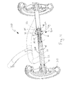
- the inventive vehicle 100 which is partly shown in Figure 4 and at the right side of Figure 1 , comprises an inventive hub system 200 according to an aspect of the invention.
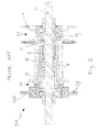
- a schematic cross section of said inventive hub system 200 is also shown in Figure 3 .
- Said hub system 200 is for a vehicle 100, for instance a pedal driven vehicle 100, a chain driven vehicle 100 and/or a go-kart, especially a vehicle for a child.
- the system 200 comprises a hub shaft 5, a driving member 2 being rotatably mounted with respect to the hub shaft 5, and a hub shell 18 being rotatably mounted with respect to the hub shaft 5, preferably at least partly by means of one or more bearings 19, especially bearings provided directly or indirectly between said hub shell 18 and the hub shaft 5 or the driving member 2.
- the inventive hub system 200 comprises a brake shoe 8 arranged for engaging the hub shell 18 such as to be coupled with said hub shell 18 temporarily, at least in rotational direction.
- the hub system 200 also comprises a brake anchor 29 arranged to be fixedly attached to a frame 22 of a vehicle 100, at least in rotational direction.
- the brake anchor 29 may for instance comprise one or more openings 34 which can be placed adjacent to a respective corresponding opening 35 in a respective frame part 22c, through which an attachments means such as a bolt can be mounted.
- the brake anchor 29 may alternatively be arranged to be fixedly attached to the frame 22 by other means.
- the hub system 200 comprises a coupling element 6 arranged for enabling coupling between the driving member 2 and the hub shell 18 in a first position of said coupling element 6, and for enabling coupling between the brake anchor 29 and the hub shell 18 in a second position of the coupling element 6.
- the coupling element 6 can be rotatably mounted with respect to the hub shaft 5, can be engaged with the driving member 2, e.g. by means of cooperating thread 37, 38, and can be movable in an axial direction or a so-called lateral direction parallel to a longitudinal direction of the hub shaft 5 between said first position and said second position.
- the hub shaft 5 is rotationally coupled to the brake shoe 8 in at least one rotational direction, and that the hub shaft 5 is also rotationally coupled to the brake anchor 29 in at least one rotational direction, preferably the same rotational direction.
- the hub shaft 5 can neither rotate forwards with respect to the brake shoe 8, nor forwards with respect to the brake anchor 29.
- the brake shoe 8 can be attached to the hub shaft 5 at least partly by means of positive locking.
- the brake shoe 8 is positively locked to a brake cone 1 provided between the hub shaft 5 and the brake shoe 8.
- the brake cone 1 can be substantially fixedly attached to the hub shaft 5.
- the brake cone 1 is provided with inner thread and is screwed onto a first end portion 5a of the hub shaft 5 which is provided with outer thread.
- an end cap 11 provided with inner tread is subsequently screwed onto outer thread of the brake cone 1. Said end cap 11 can counteract that the brake cone 1 can, during use of the hub system 200, move further laterally along the hub shaft 5 in the direction of a second end portion 5b of the hub shaft 5 opposite the first end portion 5a, e.g. due to that the end cap 11a can abut an end face 5c of the hub shaft 5.
- the hub system 200 may further comprise a brake spring 9 arranged for biasing the coupling element 6 in a direction away from the brake shoe 8 and/or towards the first position of said coupling element 6.
- the brake shoe 8 can be coupled with the hub shaft 5, e.g. rotationally coupled in at least one rotational direction, at a first location located at a first lateral side, e.g. the left side, of the driving member 2, and the brake anchor 29 can be coupled with the hub shaft 5, e.g. rotationally coupled in at least one rotational direction, at a second location, wherein the second location is located at a second lateral side of the driving member 2 and is located opposite of the first lateral side of said driving member 2, e.g. its right side.
- the brake anchor 29 and the brake shoe 8 can be coupled to each other such that the coupling there between comprises a freewheel device 44, such as for instance a roller clutch or a rattle 14, 29.
- a freewheel device 44 can be provided outside the hub shell 18, e.g. in order to save space in the hub shell 18. More preferably, the freewheel device 44 can be positioned between the brake anchor 29 and the hub shaft 5, such as is shown in Figure 3 . However, in alternative embodiments, the freewheel device 44 can have another location.
- the freewheel device 44 can be provided between the brake shoe 8 and the hub shaft 5 and/or within the hub shell 18.
- an inner portion 14 of the freewheel device can be substantially fixedly attached to the hub shaft 5, especially to its second end portion 5b.
- the inner portion 14 can be screwed onto the hub shaft 5, preferably indirectly onto to the hub shaft 5 by screwing it onto a freewheel adapter element 15, which may be screwed onto the hub shaft 5.
- a second end cap 11b can be attached to the inner portion 14 of the freewheel device, thereby preventing that said inner portion 14 of the freewheel device can substantially move towards the hub shell 18 during use.
- the second end cap 11b can be screwed onto the freewheel adapter element 15.
- the end cap 11b can abut an end face 5d of the hub shaft 5, said end cap 11b can counteract that the inner portion 14 of the freewheel device can substantially move towards the hub shell 18 during use of the hub system 200.
- the inner portion 14 of the freewheel device can in alternative embodiments be attached to the hub shaft 5 in other manners.
- the inner portion 14 may be attached to the shaft 5 by means of a bolt extending through said shaft 5 and said inner portion 14, the inner portion can be welded to the shaft 5, or the inner portion 14 can be integrally formed on the hub shaft 5.
- the end cap 11b can be an integral part of the inner portion 14.
- the hub system 200 may be arranged such that the freewheel device 44 can experiences a certain resistance when rotating in its freewheel direction due to friction between cooperating parts 14, 29 of said freewheel device 44, wherein a frictional force, such as a static frictional force, between said cooperating parts 14, 29 is larger than a frictional force, such as a static frictional force, between the coupling element 6 and the driving member 2 due to friction there between.
- a frictional force such as a static frictional force
- a frictional force such as a static frictional force
- the hub system 200 may comprise a resistance increasing element 52 in order to enable that the frictional force, such as a static frictional force, between the cooperating parts 14, 29 of the freewheel device 44 is larger than the frictional force, such as a static frictional force, due to the friction between the coupling element 6 and the driving member 2.
- said resistance increasing element 52 may be a washer 52, such as a spring washer or lock washer, or any other suitable element, which may for instance be provided between two parts 14, 29 of the freewheel device 44 which are moving with respect to each other during mutual rotation of said parts 14, 29 in a freewheeling direction of the freewheel device 44.
- the hub system 200 may be arranged to limit frictional resistance between the coupling element 6 and the driving member 2.
- the cooperating thread 37, 38 provided at these parts 2, 6 may be relatively smooth, e.g. by providing at least one of them with at least a relatively smooth outer layer, e.g. comprising Teflon.
- these parts 2, 6 may be relatively well lubricated.
- the hub system 200 can be provided in a vehicle100, such as for instance a go-kart for a child, a pedal driven vehicle, such as a chain or belt driven vehicle.
- the hub system 200 can for instance be mounted in a frame 22 of the vehicle 100.
- a central axis 45 of the hub shell 18 and/or a central axis 36 of the hub system 200 can be in line with a central axis 46 of a driven axis 13 for driving at least one wheel 30, for example a rear wheel, especially a left rear wheel, of the vehicle 100.
- the vehicle 100 can also comprise a driving axis 21 rotatably arranged in said vehicle frame 22.
- Said driving axis 21 can for instance be provided with pedals 23 and/or a driving chain-wheel 24.
- said driving chain-wheel 24 can be coupled with a driven sprocket-wheel 10 of the hub system 200, e.g. by means of a drive chain 26.
- the driving member 2 is provided with said sprocket-whee110 for cooperation with a drive chain 26.
- Said sprocket-whee110 can be fixed rotationally, and preferably also laterally or so-called axially, with respect to said driving member 2.
- the hub system 200 can be mounted to the frame 22 of the vehicle 100 at least partly by means of fixedly attaching its brake anchor 29 to the frame 22.
- the hub system 200 can be at least partly supported on bearings 47, 48 by the frame 22.
- the hub shell 18 and/or the driven axis 13 can be provided with at least one bearing element 47, 48 for facilitating that the hub shell 18 and/or the driven axis 13 can be rotatably attached to the frame 22 of a vehicle 100.
- bearings 47 e.g. one or more roller bearings 47, may be provided between the driven axis 13 and the frame 22.
- a bearing may be provided between the hub shell 18 and the frame.
- other parts of the hub system 200 can be supported on bearings.
- the hub shaft 5 e.g.
- a bearing element 48 for facilitating that the hub shaft 5 can be rotatably attached to the frame 22, and/or the hub shaft 5 may be supported on one or more bearings 48 by the frame 22.
- the latter bearing 48 is here provided indirectly on the hub shaft 5, said bearing may in alternative embodiment be placed directly onto said hub shaft 5.
- the hub system 200 is shown seen from the rear side of the hub system 200, which can correspond with the rear side of the vehicle 100.
- the driven sprocket-wheel 10 which can be directly coupled to a driving chain-wheel 24 of a vehicle 100 by means of a drive chain 26, is positioned at the right side of the hub shell 18, and the brake anchor 29 is positioned at the right side of the driven sprocket-wheel 10. It is noted that, during use, the brake anchor 29 is fixedly attached to the frame 22. All the other parts of the hub system 200 may be mounted such as to be able to rotate around the central axis 36 of the hub system 200.
- the driving member 2 which may be substantially cone-shaped and which can be a so-called driving cone 2, may be provided with outer thread 37 engaging with inner thread 38 of the coupling element 6, such that said driving member 2 can enable that the coupling element 6 moves laterally or axially with respect to the hub shaft 5.
- the coupling element 6 can move to the right.
- the coupling element 6 can move with a conical gripping surface 40 towards a corresponding conical gripping surface 39 of the hub shell 18.
- the gripping surfaces 39, 40 engage the coupling element 6 will not substantially move laterally any further, but will rotate forwards together with the driving member 2, thereby driving the engaged hub shell 18 forwards as well.
- the hub system 200 may in alternative embodiments be arranged alternatively in order to allow that the coupling element 6 can engage with the hub shell 18 in the first position in such a way that they 6, 18 are then coupled in at least one rotational direction, e.g. in such direction that the hub shell 18 rotates forwards when the coupling element 6 rotates forwards.
- the hub shell 18 can be attached to a driven axis 13 for driving at least one wheel 30.
- the hub shell 18 itself may form a driven axis 13 for driving said at least one wheel 30.
- the hub shell 18 is rotationally coupled to the driven axis 13, in both rotational directions, by fixedly attaching them to each other. This can for instance be done by means of a bolt extending trough corresponding holes 49, 50 in the driven axis 13 and hub shell 18.
- an adapter 16 which can comprise a corresponding bore hole 51, is positioned between the axis 13 and hub shell 18, such that an axis 13 can be used which has a relatively small outer diameter with respect to an inner diameter of the hub shell 18.
- the driven wheel 30 of the vehicle 100 can be rotationally coupled to the driven axis 13. Hence, a rotational movement of the hub shell 18 can be passed on to said wheel 30. Forward rotation of the hub shell 18 due to forward pedalling will thus result into forward rotation of the wheel 30.
- only one wheel 30 is driven by the driven axis 13, thereby counteracting that the vehicle cannot be steered through a turn.
- a freewheel device such as for instance a rattle or roller clutch
- a freewheel device can be provided between the coupling element 6 and the hub shell 18, e.g. provided between their gripping surfaces 39, 40 and/or formed at least partly by said gripping surfaces 39, 40.
- the hub system 200 may allow a user to coast with the vehicle 100. This is, the hub shell 18 can then keep rotating forwards, when the vehicle is rolling forwards and the pedals 23 and the driving member 2 coupled therewith are for instance held stationary with respect to the frame 22.
- the hub system 200 can be used to break.
- the coupling element 6 when the driving member 2 is rotated backwards, e.g. by pedalling backwards, the coupling element 6 can be moved to a second position.
- said second position can be axially offset from the first position.
- the coupling element 6 can be moved laterally or so-called axially with respect to the hub shaft 5, e.g. to the left, in order to be moved to said second position.
- the coupling element 6 can enable coupling between the brake anchor 29 and the hub shell 18.
- said coupling can for instance be enabled by pushing the coupling element 6 at least partly beneath a portion of the brake shoe 8 such that the brake shoe 8, which may be resilient to some extent, bends towards an inner surface 41 of the hub shell 18.
- the brake shoe 8 can grip the hub shell 18, e.g. at least partly by means of friction, and can stop said hub shell from substantially rotating with respect to the brake shoe 8, which brake shoe 8 can be kept from moving with respect to the coupling element 6 by means of cooperating gripping surfaces 42, 43 thereof.
- the hub system 200 may in alternative embodiments be arranged alternatively in order to allow that the coupling element 6 can cooperate with the brake shoe 8 in the second position such that said brake shoe 8 can then be coupled with the hub shell 18. It is noted that by stopping the hub shell 18 from moving forwards in this manner, the hub shell 18 becomes rotationally coupled, in the backward direction, with the driving member 2.
- the hub shell 18 is for instance rotationally coupled to the driving member 2 in said backward direction by means of the coupling element 6 and the brake shoe 8.
- the hub shaft 5 Since the hub shaft 5 is rotationally coupled to the brake shoe 8, in at least one rotational direction, especially the backward direction, and preferably in both rotational directions, the hub shaft 5 will here be rotated backwards when the driving member 2 is rotated backwards after a user has braked the forward rotation of the hub shell 18. It is noted that the hub shaft 5 is here coupled to the brake anchor 29 by means of freewheel device 44 which allows said hub shaft 5 to rotate backwards with respect to said brake anchor 29. As a result, by pedalling backwards after having braked, a user can make the hub shell 18 to rotate backwards. This can thus result in that the driven axis 13 attached to the hub shell 18, and the wheel 30 attached to the driven axis 13 will rotate backwards as well, thereby driving the vehicle 100 backwards.
- the vehicle 100 may be arranged such that another wheel of said vehicle is driven, for example its right rear wheel.
- the drive chain 26 can for instance be replaced by another transmission element for transmitting power from the driving axis 21 to the driving member 2.
- a drive belt may be provided, such as a teethed drive belt, and the chain-wheel and the sprocket-wheel may be replaced by corresponding pulleys or cog-wheels.
- the driving member 2 may be provided with a first gear wheel forming a connection element for cooperation with a second gear wheel forming a transmission element, e.g. for transmitting a movement of a driving axis 21 to said driving member 2, substantially directly or indirectly.
- any reference signs placed between parentheses shall not be construed as limiting the claim.
- the word 'comprising' does not exclude the presence of other features or steps then those listed in a claim.
- the words 'a' and 'an' shall not be construed as limited to 'only one', but instead are used to mean 'at least one', and do not exclude a plurality.
- the mere fact that certain measures are recited in mutually different claims does not indicate that a combination of these measures cannot be used to advantage.
Landscapes
- Engineering & Computer Science (AREA)
- Mechanical Engineering (AREA)
- General Engineering & Computer Science (AREA)
- Automatic Cycles, And Cycles In General (AREA)
- Chemical & Material Sciences (AREA)
- Combustion & Propulsion (AREA)
- Transportation (AREA)
Abstract
Description
- The invention relates to a hub system for a vehicle, such as a chain driven vehicle, for example a go-kart for a child.
- Such hub systems, for instance conventional bike hub systems, are often provided with a coaster brake arrangement.
- For example, hub systems with a coaster brake arrangement are known which comprise: a hub shaft; a driving member being rotatably mounted with respect to the hub shaft; a hub shell being rotatably mounted with respect to the hub shaft; a brake shoe arranged for engaging the hub shell such as to be coupled with said hub shell temporarily; a brake anchor arranged to be fixedly attached to a frame of a vehicle; and a coupling element arranged for enabling coupling between the driving member and the hub shell in a first position of said coupling element, and for enabling coupling between the brake anchor and the hub shell in a second position of the coupling element.
- Such hub systems are known from practice. For example, pedal driven go-karts provided with such hub system provided with a coaster brake arrangement have been sold by the company Berg Toys.
- The company Berg Toys sold for instance go-karts, wherein the brake anchor of the hub system is provided with a freewheel device. Said hub system is called a BFR hub system. It is noted that BFR stands for Brake, Forward and Reverse. Said BFR hub system allows a driver to drive forwards by pedalling forwards, to coast with the pedals remaining static when the vehicle is already rolling forwards, to brake by pedalling backwards slightly thereby activating an integrated coaster brake which comprises the brake shoe, and - due to the freewheel device - to drive backwards by pedalling further backwards after having braked.
- Vehicles, such as go-karts, provided with said BFR hub system normally have a driving axis rotatably arranged in a vehicle frame, said driving axis normally being provided with pedals and a driving chain-wheel, which generally is coupled with a driven sprocket-wheel by means of a drive chain. Commonly, said driven chain-wheel is positioned around the hub shaft of the hub system, which hub shaft is fixed in rotational direction with respect to the vehicle frame, at a first lateral side of a hub shell of the system. At a second lateral side of the hub shell, the brake anchor is fixedly attached to the frame. Further, said driven sprocket-wheel is coupled to the driving member of the hub system, thereby enabling that rotational motion of the pedals and corresponding rotational motion of the driving member can make the hub shell to rotate forwards in order to drive forwards, can brake the hub shell, and can make the hub shell to rotate backwards subsequently in order to drive backwards. In order to pass the rotational motion of the hub shell, which hub shell is thus provided between the driven sprocket-wheel and the brake anchor, on to a wheel of the vehicle, a second driving chain-wheel is fixedly connected to said hub shell. By means of a second chain, said second driving chain-wheel is coupled with a second driven sprocket-wheel fixedly provided on a driven axis for driving at least one wheel, for example a left rear wheel, of the vehicle.
- An advantage of a conventional BFR hub system over a normal coaster-brake hub system can lie in that such BFR hub system cannot only allow driving by pedalling forwards, coasting and braking, but can also allow a driver to drive rearwards after having braked.
- However, disadvantages of a conventional BFR hub system may lie in that vehicles provided with such a hub system are normally of relatively complex design, e.g. due to the two separate drive chains. Further, the assembly and/or maintenance of the hub system and/or the vehicle, and/or (re-)adjustment of parts can be relatively difficult, time-consuming, error-prone and/or labour-intensive.
- An object of the present invention is to provide an alternative hub system and/or an alternative vehicle, especially a go-kart and/or a chain driven or belt vehicle, preferably for a child. In particular, it is an object of the present invention to alleviate or solve at least one disadvantages of a conventional hub system, such as a BFR hub system, especially one of the disadvantages mentioned above. More in particular, the invention aims at providing a hub system, wherein at least one of the disadvantages of a conventional hub system is counteracted or advantages there above are obtained. Especially, the invention aims at providing a hub system which is arranged such that a vehicle provided with such hub system can be of relative simple design. In embodiments, the invention aims at providing a hub system which can enable that a vehicle provided therewith can allow driving forwards by pedalling forwards, can allow coasting, can allow braking, and can also allow driving rearwards after a user has braked, preferably without said vehicle having a relative complex design and/or without said vehicle being provided with two separate drive chains and/or an additional axis.
- In a first aspect, the present invention provides for a hub system which comprises: a hub shaft; a driving member being rotatably mounted with respect to the hub shaft; a hub shell being rotatably mounted with respect to the hub shaft; a brake shoe arranged for engaging the hub shell such as to be coupled with said hub shell temporarily; a brake anchor arranged to be fixedly attached to a frame of a vehicle; and a coupling element arranged for enabling coupling between the driving member and the hub shell in a first position of said coupling element, and for enabling coupling between the brake anchor and the hub shell in a second position of the coupling element, wherein the hub shaft is rotationally coupled to the brake shoe in at least one rotational direction, and wherein the hub shaft is also rotationally coupled to the brake anchor in at least one rotational direction.
- By rotationally coupling the hub shaft to the brake shoe in at least one rotational direction, and also rotationally coupling the hub shaft to the brake anchor in at least one rotational direction, the brake shoe and the brake anchor can be rotationally coupled to each other in at least one rotational direction via the hub shaft. Therefore, the hub system can enable that the brake shoe can be positioned at one lateral side of the driving member, and that that the brake anchor - coupled to said brake shoe by means of the hub shaft - can be positioned at the opposite lateral side of said driving member. As a result, the hub shell and/or a driven axis connected thereto can extend at a first lateral side of a sprocket-wheel attached to the driving member, whereas the brake anchor coupled to the hub shaft can be provided at the opposite lateral side of said sprocket-wheel. Hence, the rotational movement or stagnation of the hub shell can be passed onto a wheel attached to said hub shell and/or driven axis substantially directly, e.g. without needing a second driving chain-wheel, a second driven sprocket-wheel, and a second chain engaging with said sprocket-wheels.
- In embodiments, a rotational coupling between the brake anchor and the brake shoe, e.g. via the hub shell and the hub shaft, can comprises a freewheel device, such as for instance a roller clutch or a rattle. As a result, after having braked, the then rotationally coupled driving member, brake shoe and hub shell may be allowed to rotate backwards with respect to the brake anchor. Hence, the hub system can go into reverse mode, such that the vehicle can be driven backwards.
- Preferably, the freewheel device can be provided outside the hub shell. More preferably, said device can be provided between the brake anchor and the hub shaft. As a result, the diameter of the hub shell may for instance be limited to some extent. However, in alternative embodiments, the freewheel device may be located elsewhere, such as for instance between the brake shoe and the hub shaft.
- Advantageously, the hub system may be arranged such that the freewheel device experiences a certain resistance when rotating in its freewheel direction due to friction between cooperating parts of said freewheel device, wherein a frictional force between said cooperating parts is larger than a frictional force between the coupling element and the driving member due to friction there between. As a result, it can be counteracted that the driving member is unintentionally coupled to the coupling element in rotational direction due to friction there between. Actually, it may be counteracted that the coupling element and therefore the hub shaft rotate backwards together with the backwardly rotating driving member, because a resistance force of the freewheel device can prevent this. It may thus be facilitated in a relatively elegant manner that the coupling element moves from its first position towards it second position when the driving member is rotated rearwards, in stead of that the hub shaft will freewheel, which usually may be highly unwanted. Hence, it can be facilitated in an elegant manner that a rearward movement of the driving member can cause the hub shell to brake and/or to rotate backwards in stead of that a rearward movement of the driving member only results in coasting or so-called freewheeling.
- In embodiments, the hub system may comprise a resistance increasing element in order to enable that the frictional force between the cooperating parts of the freewheel device is larger than the frictional force due to the friction between the coupling element and the driving member. For example, said resistance increasing element may be a washer, such as a spring washer or lock washer, or any other suitable element, which may for instance be provided between two parts of the freewheel device which are moving with respect to each other during mutual rotation of said parts in a freewheeling direction of the freewheel device.
- In embodiments said frictional force between cooperating parts as mentioned can be a static frictional force.
- Advantageously, the hub shell can be attached to a driven axis for driving at least one wheel, or the hub shell can form a driven axis for driving at least one wheel. Hence, the driven axis of said wheel can be substantially in line with a central axis of the hub system. As a result, it can become superfluous to both mount a driven axis of the wheel to a vehicle frame and mount a parallel hub system to another part of the vehicle frame. Hence, a vehicle can be provided with a relatively simple frame.
- The invention also relates to a vehicle, such as a chain driven vehicle or a belt driven vehicle, for example a go-kart for a child.
- Advantageous embodiments of the invention are described below and in the appended claims.
- By way of non-limiting examples only, embodiments of a prior art hub system and a prior art vehicle and embodiments of the present invention are now described with reference to the accompanying figures, in which:
-
Figure 1 shows a schematic top view of a part of a conventional vehicle and a part of a vehicle according to an aspect of the invention; -
Figure 2 shows a schematic cross-sectional view of a conventional hub system of the conventional vehicle shown inFigure 1 ; -
Figure 3 shows a schematic cross-sectional view of an embodiment of an inventive hub system according to an aspect of the invention; and -
Figure 4 shows a schematic, partly cut-away perspective view of the vehicle according to an aspect of the invention shown inFigure 1 provided with the hub system shown inFigure 3 . - The embodiments disclosed herein are shown as examples only and should by no means be understood as limiting the scope of the claimed invention in any way. In this description the same or similar elements have the same or similar reference signs.
- At its left side,
Figure 1 shows a schematic top view of a part of aconventional vehicle 101 according to the prior art. Further, at its right side,Figure 1 shows a schematic top view of a part of aninventive vehicle 100 according to an aspect of the invention. For clarity sake, no steering wheels or handle bars, no front wheels, and no seats or saddles are shown inFigure 1 . - The
prior art vehicle 101, shown at the left side ofFigure 1 , is provided with aconventional hub system 201 according to the prior art, which can be better seen inFigure 2 . Here, theprior art vehicle 101 has aframe 22 and adriving axis 21 rotatably arranged in saidvehicle frame 22. Said drivingaxis 21 is provided withpedals 23 and a driving chain-wheel 24. The driving chain-wheel 24 is coupled with a driven sprocket-wheel 10 by means of adrive chain 26. Said driven sprocket-wheel 10 is positioned around ahub shaft 50 of thehub system 201 at a firstlateral side 27 of ahub shell 18. Saidhub shaft 50 is fixed in rotational direction with respect to thevehicle frame 22, e.g. by mounting it torespective frame parts 22a. At a second lateral side 28 of thehub shell 18, abrake anchor 29 is fixedly attached to theframe 22 by means of arespective frame part 22b. Further, said driven sprocket-wheel 10 is coupled to a drivingmember 2 of thehub system 201. It is noted that thevehicle 101 and itshub system 201 are arranged such as to enable that rotational motion of thepedals 23 and corresponding rotational motion of the drivingmember 2 can make thehub shell 18 to rotate forwards in order to drive thevehicle 101 forwards, can brake thehub shell 18 in order to stop thevehicle 101, and can make thehub shell 18 to rotate backwards after braking in order to drive thevehicle 101 backwards. In order to pass the rotational motion of thehub shell 18, which hub shell is thus located between the driven sprocket-wheel 10 and thebrake anchor 29, on to awheel 30 of thevehicle 101, a second driving chain-wheel 31 is fixedly attached to saidhub shell 18. By means of asecond chain 32, said second driving chain-wheel 31 is coupled with a second driven sprocket-wheel 33 fixedly attached on a drivenaxis 130 for driving at least onewheel 30, for example a leftrear wheel 30, of thevehicle 101. It is noted that said drivenaxis 130 can substantially extend through arespective part 22d of theframe 22. - The
inventive vehicle 100 according to an aspect of the invention, which is partly shown inFigure 4 and at the right side ofFigure 1 , comprises aninventive hub system 200 according to an aspect of the invention. A schematic cross section of saidinventive hub system 200 is also shown inFigure 3 .Said hub system 200 is for avehicle 100, for instance a pedal drivenvehicle 100, a chain drivenvehicle 100 and/or a go-kart, especially a vehicle for a child. Thesystem 200 comprises ahub shaft 5, a drivingmember 2 being rotatably mounted with respect to thehub shaft 5, and ahub shell 18 being rotatably mounted with respect to thehub shaft 5, preferably at least partly by means of one ormore bearings 19, especially bearings provided directly or indirectly between saidhub shell 18 and thehub shaft 5 or the drivingmember 2. Further, theinventive hub system 200 comprises a brake shoe 8 arranged for engaging thehub shell 18 such as to be coupled with saidhub shell 18 temporarily, at least in rotational direction. Thehub system 200 also comprises abrake anchor 29 arranged to be fixedly attached to aframe 22 of avehicle 100, at least in rotational direction. As can be seen inFigures 3 and4 , thebrake anchor 29 may for instance comprise one ormore openings 34 which can be placed adjacent to a respectivecorresponding opening 35 in a respective frame part 22c, through which an attachments means such as a bolt can be mounted. However, thebrake anchor 29 may alternatively be arranged to be fixedly attached to theframe 22 by other means. Furthermore, thehub system 200 comprises acoupling element 6 arranged for enabling coupling between the drivingmember 2 and thehub shell 18 in a first position of saidcoupling element 6, and for enabling coupling between thebrake anchor 29 and thehub shell 18 in a second position of thecoupling element 6. Preferably, thecoupling element 6 can be rotatably mounted with respect to thehub shaft 5, can be engaged with the drivingmember 2, e.g. by means of cooperatingthread hub shaft 5 between said first position and said second position. It is noted that thehub shaft 5 is rotationally coupled to the brake shoe 8 in at least one rotational direction, and that thehub shaft 5 is also rotationally coupled to thebrake anchor 29 in at least one rotational direction, preferably the same rotational direction. Preferably, thehub shaft 5 can neither rotate forwards with respect to the brake shoe 8, nor forwards with respect to thebrake anchor 29. For example, the brake shoe 8 can be attached to thehub shaft 5 at least partly by means of positive locking. Here, the brake shoe 8 is positively locked to a brake cone 1 provided between thehub shaft 5 and the brake shoe 8. - It is noted that the brake cone 1 can be substantially fixedly attached to the
hub shaft 5. Here, the brake cone 1 is provided with inner thread and is screwed onto a first end portion 5a of thehub shaft 5 which is provided with outer thread. Here, an end cap 11 provided with inner tread is subsequently screwed onto outer thread of the brake cone 1. Said end cap 11 can counteract that the brake cone 1 can, during use of thehub system 200, move further laterally along thehub shaft 5 in the direction of a second end portion 5b of thehub shaft 5 opposite the first end portion 5a, e.g. due to that the end cap 11a can abut an end face 5c of thehub shaft 5. - In embodiments, the
hub system 200 may further comprise a brake spring 9 arranged for biasing thecoupling element 6 in a direction away from the brake shoe 8 and/or towards the first position of saidcoupling element 6. - Advantageously, the brake shoe 8 can be coupled with the
hub shaft 5, e.g. rotationally coupled in at least one rotational direction, at a first location located at a first lateral side, e.g. the left side, of the drivingmember 2, and thebrake anchor 29 can be coupled with thehub shaft 5, e.g. rotationally coupled in at least one rotational direction, at a second location, wherein the second location is located at a second lateral side of the drivingmember 2 and is located opposite of the first lateral side of said drivingmember 2, e.g. its right side. - In embodiments, the
brake anchor 29 and the brake shoe 8 can be coupled to each other such that the coupling there between comprises afreewheel device 44, such as for instance a roller clutch or arattle freewheel device 44 can be provided outside thehub shell 18, e.g. in order to save space in thehub shell 18. More preferably, thefreewheel device 44 can be positioned between thebrake anchor 29 and thehub shaft 5, such as is shown inFigure 3 . However, in alternative embodiments, thefreewheel device 44 can have another location. For example, thefreewheel device 44 can be provided between the brake shoe 8 and thehub shaft 5 and/or within thehub shell 18. - Advantageously, an
inner portion 14 of the freewheel device can be substantially fixedly attached to thehub shaft 5, especially to its second end portion 5b. For example, theinner portion 14 can be screwed onto thehub shaft 5, preferably indirectly onto to thehub shaft 5 by screwing it onto afreewheel adapter element 15, which may be screwed onto thehub shaft 5. In embodiments, a second end cap 11b can be attached to theinner portion 14 of the freewheel device, thereby preventing that saidinner portion 14 of the freewheel device can substantially move towards thehub shell 18 during use. In order to lock saidinner portion 14 substantially with respect to thehub shaft 5, at least in one axial direction, e.g. at least in a direction towards thehub shell 18, the second end cap 11b can be screwed onto thefreewheel adapter element 15. Since the end cap 11b can abut anend face 5d of thehub shaft 5, said end cap 11b can counteract that theinner portion 14 of the freewheel device can substantially move towards thehub shell 18 during use of thehub system 200. Further, it is noted that theinner portion 14 of the freewheel device can in alternative embodiments be attached to thehub shaft 5 in other manners. For example, theinner portion 14 may be attached to theshaft 5 by means of a bolt extending through saidshaft 5 and saidinner portion 14, the inner portion can be welded to theshaft 5, or theinner portion 14 can be integrally formed on thehub shaft 5. In yet a further alternative embodiment, the end cap 11b can be an integral part of theinner portion 14. - Advantageously, the
hub system 200 may be arranged such that thefreewheel device 44 can experiences a certain resistance when rotating in its freewheel direction due to friction between cooperatingparts freewheel device 44, wherein a frictional force, such as a static frictional force, between said cooperatingparts coupling element 6 and the drivingmember 2 due to friction there between. As a result, it can be counteracted that the drivingmember 2 is unintentionally coupled to thecoupling element 6 in rotational direction due to friction there between. Actually, it may be counteracted that thecoupling element 2, and therefore also thehub shaft 5, rotates backwards together with the backwardly rotating drivingmember 2, because a resistance force of thefreewheel device 44 can prevent this. It may thus be facilitated in a relatively elegant manner that thecoupling element 6 moves from its first position towards it second position when the drivingmember 2 is rotated rearwards, in stead of that thehub shaft 5 will freewheel, which can be highly undesirable. Hence, it can thus be facilitated that a rearward movement of the drivingmember 2 causes thehub shell 5 to brake and/or to rotate backwards in stead of that a rearward movement of the drivingmember 2 only results in coasting or so-called freewheeling. - In embodiments, the
hub system 200 may comprise aresistance increasing element 52 in order to enable that the frictional force, such as a static frictional force, between the cooperatingparts freewheel device 44 is larger than the frictional force, such as a static frictional force, due to the friction between thecoupling element 6 and the drivingmember 2. For example, saidresistance increasing element 52 may be awasher 52, such as a spring washer or lock washer, or any other suitable element, which may for instance be provided between twoparts freewheel device 44 which are moving with respect to each other during mutual rotation of saidparts freewheel device 44. - Additionally or alternatively, the
hub system 200 may be arranged to limit frictional resistance between thecoupling element 6 and the drivingmember 2. For example, the cooperatingthread parts parts - It is noted that the
hub system 200 can be provided in a vehicle100, such as for instance a go-kart for a child, a pedal driven vehicle, such as a chain or belt driven vehicle. Thehub system 200 can for instance be mounted in aframe 22 of thevehicle 100. As can be seen inFigure 4 , a central axis 45 of thehub shell 18 and/or a central axis 36 of thehub system 200 can be in line with acentral axis 46 of a drivenaxis 13 for driving at least onewheel 30, for example a rear wheel, especially a left rear wheel, of thevehicle 100. - In embodiments, the
vehicle 100 can also comprise a drivingaxis 21 rotatably arranged in saidvehicle frame 22. Said drivingaxis 21 can for instance be provided withpedals 23 and/or a driving chain-wheel 24. For example, said driving chain-wheel 24 can be coupled with a driven sprocket-wheel 10 of thehub system 200, e.g. by means of adrive chain 26. Preferably, the drivingmember 2 is provided with said sprocket-whee110 for cooperation with adrive chain 26. Said sprocket-whee110 can be fixed rotationally, and preferably also laterally or so-called axially, with respect to said drivingmember 2. - Advantageously, the
hub system 200 can be mounted to theframe 22 of thevehicle 100 at least partly by means of fixedly attaching itsbrake anchor 29 to theframe 22. - Additionally or alternatively, the
hub system 200 can be at least partly supported onbearings frame 22. In embodiments, thehub shell 18 and/or the drivenaxis 13 can be provided with at least one bearingelement hub shell 18 and/or the drivenaxis 13 can be rotatably attached to theframe 22 of avehicle 100. For example,bearings 47, e.g. one ormore roller bearings 47, may be provided between the drivenaxis 13 and theframe 22. Alternatively or additionally, a bearing may be provided between thehub shell 18 and the frame. Additionally or alternatively, other parts of thehub system 200 can be supported on bearings. For example, thehub shaft 5, e.g. at an end protruding from thehub shell 18 at the side of thebrake anchor 29, may be provided with a bearingelement 48 for facilitating that thehub shaft 5 can be rotatably attached to theframe 22, and/or thehub shaft 5 may be supported on one ormore bearings 48 by theframe 22. Although thelatter bearing 48 is here provided indirectly on thehub shaft 5, said bearing may in alternative embodiment be placed directly onto saidhub shaft 5. - The operation of a
hub system 200 according to the invention will now be briefly described at the hand ofFigure 3 . Here, thehub system 200 is shown seen from the rear side of thehub system 200, which can correspond with the rear side of thevehicle 100. In the here shown exemplary embodiment, the driven sprocket-wheel 10, which can be directly coupled to a driving chain-wheel 24 of avehicle 100 by means of adrive chain 26, is positioned at the right side of thehub shell 18, and thebrake anchor 29 is positioned at the right side of the driven sprocket-wheel 10. It is noted that, during use, thebrake anchor 29 is fixedly attached to theframe 22. All the other parts of thehub system 200 may be mounted such as to be able to rotate around the central axis 36 of thehub system 200. It is further noted that, except for thecoupling element 6, all hub system parts discussed above, may be prevented from moving laterally, e.g. axially, during use of thehub system 200. When the drivingmember 2 is rotated forwards, e.g. by means of pedalling forwards, said drivingmember 2 moves thecoupling element 6 to the first position in which saidelement 6 enables coupling, especially rotational coupling in at least one direction, between the drivingmember 2 and thehub shell 18. For example the drivingmember 2, which may be substantially cone-shaped and which can be a so-calleddriving cone 2, may be provided withouter thread 37 engaging withinner thread 38 of thecoupling element 6, such that said drivingmember 2 can enable that thecoupling element 6 moves laterally or axially with respect to thehub shaft 5. Here, when the drivingmember 2 is rotated forwards, thecoupling element 6 can move to the right. In embodiments, thecoupling element 6 can move with a conicalgripping surface 40 towards a corresponding conical grippingsurface 39 of thehub shell 18. As soon as the grippingsurfaces coupling element 6 will not substantially move laterally any further, but will rotate forwards together with the drivingmember 2, thereby driving the engagedhub shell 18 forwards as well. Although thecoupling element 6 and thehub shell 18 are here provided with saidgripping surfaces hub system 200 may in alternative embodiments be arranged alternatively in order to allow that thecoupling element 6 can engage with thehub shell 18 in the first position in such a way that they 6, 18 are then coupled in at least one rotational direction, e.g. in such direction that thehub shell 18 rotates forwards when thecoupling element 6 rotates forwards. - Moreover, it is noted that the
hub shell 18 can be attached to a drivenaxis 13 for driving at least onewheel 30. Alternatively, thehub shell 18 itself may form a drivenaxis 13 for driving said at least onewheel 30. Here, thehub shell 18 is rotationally coupled to the drivenaxis 13, in both rotational directions, by fixedly attaching them to each other. This can for instance be done by means of a bolt extendingtrough corresponding holes 49, 50 in the drivenaxis 13 andhub shell 18. In the embodiment shown, anadapter 16, which can comprise acorresponding bore hole 51, is positioned between theaxis 13 andhub shell 18, such that anaxis 13 can be used which has a relatively small outer diameter with respect to an inner diameter of thehub shell 18. - Furthermore, it is noted that the driven
wheel 30 of thevehicle 100 can be rotationally coupled to the drivenaxis 13. Hence, a rotational movement of thehub shell 18 can be passed on to saidwheel 30. Forward rotation of thehub shell 18 due to forward pedalling will thus result into forward rotation of thewheel 30. Preferably, only onewheel 30 is driven by the drivenaxis 13, thereby counteracting that the vehicle cannot be steered through a turn. - In embodiments, a freewheel device, such as for instance a rattle or roller clutch, can be provided between the
coupling element 6 and thehub shell 18, e.g. provided between theirgripping surfaces surfaces hub system 200 may allow a user to coast with thevehicle 100. This is, thehub shell 18 can then keep rotating forwards, when the vehicle is rolling forwards and thepedals 23 and the drivingmember 2 coupled therewith are for instance held stationary with respect to theframe 22. - Further, the
hub system 200 can be used to break. Thereto, when the drivingmember 2 is rotated backwards, e.g. by pedalling backwards, thecoupling element 6 can be moved to a second position. Preferably, said second position can be axially offset from the first position. For example, thecoupling element 6 can be moved laterally or so-called axially with respect to thehub shaft 5, e.g. to the left, in order to be moved to said second position. In said second position, thecoupling element 6 can enable coupling between thebrake anchor 29 and thehub shell 18. Advantageously, said coupling can for instance be enabled by pushing thecoupling element 6 at least partly beneath a portion of the brake shoe 8 such that the brake shoe 8, which may be resilient to some extent, bends towards aninner surface 41 of thehub shell 18. Hence, the brake shoe 8 can grip thehub shell 18, e.g. at least partly by means of friction, and can stop said hub shell from substantially rotating with respect to the brake shoe 8, which brake shoe 8 can be kept from moving with respect to thecoupling element 6 by means of cooperating grippingsurfaces coupling element 6 and the brake shoe 8 are here provided with saidgripping surfaces hub system 200 may in alternative embodiments be arranged alternatively in order to allow that thecoupling element 6 can cooperate with the brake shoe 8 in the second position such that said brake shoe 8 can then be coupled with thehub shell 18. It is noted that by stopping thehub shell 18 from moving forwards in this manner, thehub shell 18 becomes rotationally coupled, in the backward direction, with the drivingmember 2. Here, thehub shell 18 is for instance rotationally coupled to the drivingmember 2 in said backward direction by means of thecoupling element 6 and the brake shoe 8. Since thehub shaft 5 is rotationally coupled to the brake shoe 8, in at least one rotational direction, especially the backward direction, and preferably in both rotational directions, thehub shaft 5 will here be rotated backwards when the drivingmember 2 is rotated backwards after a user has braked the forward rotation of thehub shell 18. It is noted that thehub shaft 5 is here coupled to thebrake anchor 29 by means offreewheel device 44 which allows saidhub shaft 5 to rotate backwards with respect to saidbrake anchor 29. As a result, by pedalling backwards after having braked, a user can make thehub shell 18 to rotate backwards. This can thus result in that the drivenaxis 13 attached to thehub shell 18, and thewheel 30 attached to the drivenaxis 13 will rotate backwards as well, thereby driving thevehicle 100 backwards. - The invention is not in any way limited to the exemplary embodiments presented in the description and drawings. All combinations (of parts) of the embodiments shown and described are explicitly understood to fall within the scope of the invention. Moreover, it will be understood that many variations are possible within the scope of the invention as formulated in the appended claims.
- For example, the
vehicle 100 may be arranged such that another wheel of said vehicle is driven, for example its right rear wheel. - As a further example, in embodiments, the
drive chain 26 can for instance be replaced by another transmission element for transmitting power from the drivingaxis 21 to the drivingmember 2. For example, a drive belt may be provided, such as a teethed drive belt, and the chain-wheel and the sprocket-wheel may be replaced by corresponding pulleys or cog-wheels. As another example, the drivingmember 2 may be provided with a first gear wheel forming a connection element for cooperation with a second gear wheel forming a transmission element, e.g. for transmitting a movement of a drivingaxis 21 to said drivingmember 2, substantially directly or indirectly. - However, other modifications, variations and alternatives are also possible. The specifications, drawings and examples are, accordingly, to be regarded in an illustrative rather than in a restrictive sense.
- In the claims, any reference signs placed between parentheses shall not be construed as limiting the claim. The word 'comprising' does not exclude the presence of other features or steps then those listed in a claim. Furthermore, the words 'a' and 'an' shall not be construed as limited to 'only one', but instead are used to mean 'at least one', and do not exclude a plurality. The mere fact that certain measures are recited in mutually different claims does not indicate that a combination of these measures cannot be used to advantage.
Claims (15)
- Hub system (200) for a vehicle (100), such as a chain or belt driven vehicle for example a go-kart for a child, comprising:a hub shaft (5);a driving member (2) being rotatably mounted with respect to the hub shaft (5);a hub shell (18) being rotatably mounted with respect to the hub shaft (5);a brake shoe (8) arranged for engaging the hub shell (18) such as to be coupled with said hub shell (18) temporarily;a brake anchor (29) arranged to be fixedly attached to a frame of a vehicle (100); anda coupling element (6) arranged for enabling coupling between the driving member (2) and the hub shell (18) in a first position of said coupling element (6), and for enabling coupling between the brake anchor (29) and the hub shell (18) in a second position of the coupling element (6),wherein the hub shaft (5) is rotationally coupled to the brake shoe (8) in at least one rotational direction at a first location located at a first lateral side of the driving member (2), and wherein the hub shaft (5) is rotationally coupled to the brake anchor (29) in at least one rotational direction at a second location located at a second lateral side of the driving member (2) and opposite of the first lateral side of said driving member (2).
- Hub system (200) according to claim 1, wherein a rotational coupling between the brake anchor (29) and the brake shoe (8), e.g. via the hub shell (18) and the hub shaft (5), comprises a freewheel device (44), such as for instance a roller clutch or a rattle.
- Hub system (200) according to claim 2, wherein the freewheel device (44) is provided outside the hub shell (18), preferably between the brake anchor (29) and the hub shaft (5).
- Hub system (200) according to claim 2 or 3, wherein said hub system (200) is arranged such that the freewheel device (44) experiences a certain resistance when the hub shaft (5) rotates in its freewheel direction due to friction between cooperating parts (14, 29) of said freewheel device (44), wherein a frictional force between said cooperating parts (14, 29) is larger than a frictional force between the coupling element (6) and the driving member (2) due to friction there between.
- Hub system (200) according to claim 4, further comprising a resistance increasing element (52) such as a washer (52), e.g. a spring washer or lock washer, which may be provided at least partly between the cooperating parts (14, 29) of the freewheel device (44).
- Hub system (200) according to any one of the preceding claims, wherein the hub shell (18) is attached to a driven axis (13) for driving at least one wheel (30) or wherein the hub shell (18) forms a driven axis (13) for driving at least one wheel (30).
- Hub system (200) according to any one of the preceding claims, wherein the hub shell (18) and/or the driven axis (13) is provided with a bearing element (47, 48) for facilitating that the hub shell (18) and/or the driven axis (13) can be rotatably attached to a frame (22) of a vehicle (100).
- Hub system (200) according to any one of the preceding claims, wherein the hub shaft (5) is provided with a bearing element (48) for facilitating that the hub shaft (5) can be rotatably attached to a frame (22) of a vehicle (100).
- Hub system (200) according to any one of the preceding claims, wherein the coupling element (6) is rotatably mounted with respect to the hub shaft (5), is engaged with the driving member (2), and is movable in an axial or so-called lateral direction parallel to a longitudinal direction of the hub shaft (5) between the first position and the second position.
- Hub system (200) according to any one of the preceding claims, wherein the hub system (200) is arranged such that the coupling element (6) engages with the hub shell (18) in the first position such that they (6, 18) are then coupled in at least one rotational direction.
- Hub system (200) according to any one of the preceding claims, wherein the hub system (200) is arranged such that the coupling element (6) cooperates with the brake shoe (8) in the second position such that the brake shoe (8) is then coupled with the hub shell (18).
- Hub system (200) according to any one of the preceding claims, wherein the driving member (2) is provided with a connection element (10), such as for instance a sprocket-wheel(10), a first gear wheel or a pulley, wherein said connection element (10) is arranged for cooperation with a transmission element (26) for transmitting a movement of a driving axis (21) to said driving member (2), said transmission element (26) for instance being a drive chain (26), a second gear wheel, or a drive belt.
- Vehicle (100), such as a chain or belt driven vehicle for example a go-kart for a child, comprising a hub system (200) according to any one of the preceding claims.
- Vehicle (100) according to claim 13, wherein a central axis (45) of the hub shell (18) is in line with a central axis (46) of a driven axis (13) for driving at least one wheel (30), for example a rear wheel, especially a left rear wheel, of the vehicle (100).
- Vehicle (100) according to claim 13 or 14, wherein the hub shell (18) and/or the driven axis (13), and/or the hub shaft (5) is supported on bearings by a frame (22) of said vehicle (100).
Applications Claiming Priority (1)
| Application Number | Priority Date | Filing Date | Title |
|---|---|---|---|
| NL2012240A NL2012240C2 (en) | 2014-02-11 | 2014-02-11 | Hub system and vehicle. |
Publications (2)
| Publication Number | Publication Date |
|---|---|
| EP2905212A1 true EP2905212A1 (en) | 2015-08-12 |
| EP2905212B1 EP2905212B1 (en) | 2024-12-11 |
Family
ID=50687580
Family Applications (1)
| Application Number | Title | Priority Date | Filing Date |
|---|---|---|---|
| EP15154498.8A Active EP2905212B1 (en) | 2014-02-11 | 2015-02-10 | Hub system and vehicle |
Country Status (3)
| Country | Link |
|---|---|
| US (1) | US9610805B2 (en) |
| EP (1) | EP2905212B1 (en) |
| NL (1) | NL2012240C2 (en) |
Cited By (1)
| Publication number | Priority date | Publication date | Assignee | Title |
|---|---|---|---|---|
| EP3348466A1 (en) * | 2017-01-12 | 2018-07-18 | Gerdes, Clemens | Device for changing movement variables for a muscle-operated vehicle |
Families Citing this family (5)
| Publication number | Priority date | Publication date | Assignee | Title |
|---|---|---|---|---|
| RU177600U1 (en) * | 2017-07-21 | 2018-03-01 | Иван Викторович Лебедев | FRAME OF A THREE-WHEEL BIKE |
| CN107697221A (en) * | 2017-08-31 | 2018-02-16 | 浙江栋马童车股份有限公司 | A kind of transmission device and the kart with the transmission device |
| JP6439024B1 (en) * | 2017-10-27 | 2018-12-19 | 株式会社シマノ | Bicycle hub unit and bicycle wheel assembly |
| FR3079412B1 (en) * | 2018-04-03 | 2022-02-11 | Colin Gallois | WHEELCHAIR |
| US20250108660A1 (en) * | 2023-09-28 | 2025-04-03 | Wei-Yueh CHANG | Bicycle hub kit |
Citations (3)
| Publication number | Priority date | Publication date | Assignee | Title |
|---|---|---|---|---|
| US4147243A (en) * | 1976-11-27 | 1979-04-03 | Shimano Industrial Company Limited | Multi-speed transmission hub for a bicycle |
| US5027930A (en) * | 1989-01-23 | 1991-07-02 | Hess-Reed Partners | Coaster brake assembly |
| US6386566B1 (en) * | 2001-04-03 | 2002-05-14 | Progress Place, L.L.C. | Freewheeling drive having forward, reverse and braking capability |
Family Cites Families (5)
| Publication number | Priority date | Publication date | Assignee | Title |
|---|---|---|---|---|
| US2572182A (en) * | 1946-06-20 | 1951-10-23 | Cleveland Welding Co | Coaster brake |
| US2613763A (en) * | 1948-04-29 | 1952-10-14 | Bendix Aviat Corp | Coaster brake for velocipedes |
| DE3340407A1 (en) * | 1983-11-09 | 1985-06-27 | Sanitätshaus Heinrich Oesterreich GmbH, 2800 Bremen | MEDICAL ELEVATOR |
| DE19618636A1 (en) * | 1996-05-09 | 1997-11-13 | Fichtel & Sachs Ag | Multi-speed hub with coaster brake for bicycles |
| DE602005006965D1 (en) * | 2005-03-09 | 2008-07-03 | Shimano Kk | Drive hub with brake for a go-kart |
-
2014
- 2014-02-11 NL NL2012240A patent/NL2012240C2/en active
-
2015
- 2015-02-06 US US14/615,980 patent/US9610805B2/en active Active
- 2015-02-10 EP EP15154498.8A patent/EP2905212B1/en active Active
Patent Citations (3)
| Publication number | Priority date | Publication date | Assignee | Title |
|---|---|---|---|---|
| US4147243A (en) * | 1976-11-27 | 1979-04-03 | Shimano Industrial Company Limited | Multi-speed transmission hub for a bicycle |
| US5027930A (en) * | 1989-01-23 | 1991-07-02 | Hess-Reed Partners | Coaster brake assembly |
| US6386566B1 (en) * | 2001-04-03 | 2002-05-14 | Progress Place, L.L.C. | Freewheeling drive having forward, reverse and braking capability |
Cited By (1)
| Publication number | Priority date | Publication date | Assignee | Title |
|---|---|---|---|---|
| EP3348466A1 (en) * | 2017-01-12 | 2018-07-18 | Gerdes, Clemens | Device for changing movement variables for a muscle-operated vehicle |
Also Published As
| Publication number | Publication date |
|---|---|
| EP2905212B1 (en) | 2024-12-11 |
| NL2012240C2 (en) | 2015-08-17 |
| US20150224824A1 (en) | 2015-08-13 |
| US9610805B2 (en) | 2017-04-04 |
Similar Documents
| Publication | Publication Date | Title |
|---|---|---|
| US9610805B2 (en) | Hub system and vehicle | |
| CN104220326B (en) | For the transmission system of dual-power bicycle | |
| US9199509B2 (en) | Bicycle hub | |
| JP3438203B2 (en) | Bicycle hub | |
| US8936144B2 (en) | Hub with a toothed disk freewheel | |
| TWI593599B (en) | Multi-sprocket configurations for bicycle transmissions and rear wheel axle configurations with this multi-sprocket configuration | |
| JP3563322B2 (en) | Bicycle freewheel | |
| EP1881221B1 (en) | Bicycle freewheel | |
| US20110168511A1 (en) | Bicycle hub assembly | |
| US9103392B2 (en) | Hub with mechanism to permit backwards movement without pedal movement | |
| JP5634842B2 (en) | Planetary gear mechanism and hub motor device for battery-assisted bicycle equipped with the same | |
| JP2005029072A (en) | Outer for bicycle hub and bicycle hub | |
| US10525768B2 (en) | Bicycle hub assembly | |
| US20170050465A1 (en) | Rear Hub and Bicycle Axle | |
| US20190031288A1 (en) | Bicycle sprocket assembly and bicycle drive train | |
| US11052961B2 (en) | Selectable motor clutch, system, and method | |
| KR102914477B1 (en) | Torque transistors and electric bicycles with torque transistors | |
| US11730644B2 (en) | Wheelchair | |
| JP2007290606A (en) | Hub for bicycle | |
| US10427754B2 (en) | Continuous derailleur of bicycle | |
| JP2005225289A (en) | Vehicle driving force transmission structure | |
| TW201811609A (en) | Improvements relating to bicycle transmissions | |
| EP3615406B1 (en) | Bicycle wheel axle assembly | |
| JP6179704B2 (en) | Electric hub device and electric bicycle | |
| WO2006122347A1 (en) | Responsive bicycle drive mechanism |
Legal Events
| Date | Code | Title | Description |
|---|---|---|---|
| PUAI | Public reference made under article 153(3) epc to a published international application that has entered the european phase |
Free format text: ORIGINAL CODE: 0009012 |
|
| AK | Designated contracting states |
Kind code of ref document: A1 Designated state(s): AL AT BE BG CH CY CZ DE DK EE ES FI FR GB GR HR HU IE IS IT LI LT LU LV MC MK MT NL NO PL PT RO RS SE SI SK SM TR |
|
| AX | Request for extension of the european patent |
Extension state: BA ME |
|
| RBV | Designated contracting states (corrected) |
Designated state(s): AL AT BE BG CH CY CZ DE DK EE ES FI FR GB GR HR HU IE IS IT LI LT LU LV MC MK MT NL NO PL PT RO RS SE SI SK SM TR |
|
| 17P | Request for examination filed |
Effective date: 20160211 |
|
| 17Q | First examination report despatched |
Effective date: 20160523 |
|
| RIC1 | Information provided on ipc code assigned before grant |
Ipc: B60B 27/00 20060101ALN20170321BHEP Ipc: B60B 27/02 20060101AFI20170321BHEP Ipc: B60B 27/04 20060101ALN20170321BHEP |
|
| GRAP | Despatch of communication of intention to grant a patent |
Free format text: ORIGINAL CODE: EPIDOSNIGR1 |
|
| STAA | Information on the status of an ep patent application or granted ep patent |
Free format text: STATUS: GRANT OF PATENT IS INTENDED |
|
| INTG | Intention to grant announced |
Effective date: 20170502 |
|
| GRAJ | Information related to disapproval of communication of intention to grant by the applicant or resumption of examination proceedings by the epo deleted |
Free format text: ORIGINAL CODE: EPIDOSDIGR1 |
|
| STAA | Information on the status of an ep patent application or granted ep patent |
Free format text: STATUS: EXAMINATION IS IN PROGRESS |
|
| INTC | Intention to grant announced (deleted) | ||
| RIC1 | Information provided on ipc code assigned before grant |
Ipc: B60B 27/00 20060101ALN20170725BHEP Ipc: B60B 27/04 20060101ALN20170725BHEP Ipc: B60B 27/02 20060101AFI20170725BHEP |
|
| REG | Reference to a national code |
Ref country code: DE Ref legal event code: R079 Free format text: PREVIOUS MAIN CLASS: B62L0005020000 Ipc: B60B0027020000 Ref country code: DE Ref legal event code: R079 Ref document number: 602015090610 Country of ref document: DE Free format text: PREVIOUS MAIN CLASS: B62L0005020000 Ipc: B60B0027020000 |
|
| GRAP | Despatch of communication of intention to grant a patent |
Free format text: ORIGINAL CODE: EPIDOSNIGR1 |
|
| STAA | Information on the status of an ep patent application or granted ep patent |
Free format text: STATUS: GRANT OF PATENT IS INTENDED |
|
| RIC1 | Information provided on ipc code assigned before grant |
Ipc: B60B 27/04 20060101ALN20240712BHEP Ipc: B60B 27/00 20060101ALN20240712BHEP Ipc: F16D 23/12 20060101ALI20240712BHEP Ipc: F16D 67/02 20060101ALI20240712BHEP Ipc: F16D 41/24 20060101ALI20240712BHEP Ipc: F16D 13/26 20060101ALI20240712BHEP Ipc: B62K 5/02 20130101ALI20240712BHEP Ipc: B60B 35/12 20060101ALI20240712BHEP Ipc: B62M 9/02 20060101ALI20240712BHEP Ipc: B62L 5/02 20060101ALI20240712BHEP Ipc: B60B 27/02 20060101AFI20240712BHEP |
|
| INTG | Intention to grant announced |
Effective date: 20240724 |
|
| GRAS | Grant fee paid |
Free format text: ORIGINAL CODE: EPIDOSNIGR3 |
|
| GRAA | (expected) grant |
Free format text: ORIGINAL CODE: 0009210 |
|
| STAA | Information on the status of an ep patent application or granted ep patent |
Free format text: STATUS: THE PATENT HAS BEEN GRANTED |
|
| AK | Designated contracting states |
Kind code of ref document: B1 Designated state(s): AL AT BE BG CH CY CZ DE DK EE ES FI FR GB GR HR HU IE IS IT LI LT LU LV MC MK MT NL NO PL PT RO RS SE SI SK SM TR |
|
| REG | Reference to a national code |
Ref country code: GB Ref legal event code: FG4D |
|
| REG | Reference to a national code |
Ref country code: CH Ref legal event code: EP |
|
| REG | Reference to a national code |
Ref country code: IE Ref legal event code: FG4D |
|
| REG | Reference to a national code |
Ref country code: DE Ref legal event code: R096 Ref document number: 602015090610 Country of ref document: DE |
|
| REG | Reference to a national code |
Ref country code: NL Ref legal event code: FP |
|
| REG | Reference to a national code |
Ref country code: LT Ref legal event code: MG9D |
|
| PG25 | Lapsed in a contracting state [announced via postgrant information from national office to epo] |
Ref country code: HR Free format text: LAPSE BECAUSE OF FAILURE TO SUBMIT A TRANSLATION OF THE DESCRIPTION OR TO PAY THE FEE WITHIN THE PRESCRIBED TIME-LIMIT Effective date: 20241211 |
|
| PG25 | Lapsed in a contracting state [announced via postgrant information from national office to epo] |
Ref country code: FI Free format text: LAPSE BECAUSE OF FAILURE TO SUBMIT A TRANSLATION OF THE DESCRIPTION OR TO PAY THE FEE WITHIN THE PRESCRIBED TIME-LIMIT Effective date: 20241211 |
|
| PG25 | Lapsed in a contracting state [announced via postgrant information from national office to epo] |
Ref country code: BG Free format text: LAPSE BECAUSE OF FAILURE TO SUBMIT A TRANSLATION OF THE DESCRIPTION OR TO PAY THE FEE WITHIN THE PRESCRIBED TIME-LIMIT Effective date: 20241211 |
|
| PG25 | Lapsed in a contracting state [announced via postgrant information from national office to epo] |
Ref country code: ES Free format text: LAPSE BECAUSE OF FAILURE TO SUBMIT A TRANSLATION OF THE DESCRIPTION OR TO PAY THE FEE WITHIN THE PRESCRIBED TIME-LIMIT Effective date: 20241211 |
|
| PG25 | Lapsed in a contracting state [announced via postgrant information from national office to epo] |
Ref country code: NO Free format text: LAPSE BECAUSE OF FAILURE TO SUBMIT A TRANSLATION OF THE DESCRIPTION OR TO PAY THE FEE WITHIN THE PRESCRIBED TIME-LIMIT Effective date: 20250311 |
|
| PG25 | Lapsed in a contracting state [announced via postgrant information from national office to epo] |
Ref country code: LV Free format text: LAPSE BECAUSE OF FAILURE TO SUBMIT A TRANSLATION OF THE DESCRIPTION OR TO PAY THE FEE WITHIN THE PRESCRIBED TIME-LIMIT Effective date: 20241211 Ref country code: GR Free format text: LAPSE BECAUSE OF FAILURE TO SUBMIT A TRANSLATION OF THE DESCRIPTION OR TO PAY THE FEE WITHIN THE PRESCRIBED TIME-LIMIT Effective date: 20250312 |
|
| PG25 | Lapsed in a contracting state [announced via postgrant information from national office to epo] |
Ref country code: RS Free format text: LAPSE BECAUSE OF FAILURE TO SUBMIT A TRANSLATION OF THE DESCRIPTION OR TO PAY THE FEE WITHIN THE PRESCRIBED TIME-LIMIT Effective date: 20250311 |
|
| REG | Reference to a national code |
Ref country code: AT Ref legal event code: MK05 Ref document number: 1750122 Country of ref document: AT Kind code of ref document: T Effective date: 20241211 |
|
| PG25 | Lapsed in a contracting state [announced via postgrant information from national office to epo] |
Ref country code: SM Free format text: LAPSE BECAUSE OF FAILURE TO SUBMIT A TRANSLATION OF THE DESCRIPTION OR TO PAY THE FEE WITHIN THE PRESCRIBED TIME-LIMIT Effective date: 20241211 |
|
| PG25 | Lapsed in a contracting state [announced via postgrant information from national office to epo] |
Ref country code: PL Free format text: LAPSE BECAUSE OF FAILURE TO SUBMIT A TRANSLATION OF THE DESCRIPTION OR TO PAY THE FEE WITHIN THE PRESCRIBED TIME-LIMIT Effective date: 20241211 |
|
| PG25 | Lapsed in a contracting state [announced via postgrant information from national office to epo] |
Ref country code: IS Free format text: LAPSE BECAUSE OF FAILURE TO SUBMIT A TRANSLATION OF THE DESCRIPTION OR TO PAY THE FEE WITHIN THE PRESCRIBED TIME-LIMIT Effective date: 20250411 |
|
| PG25 | Lapsed in a contracting state [announced via postgrant information from national office to epo] |
Ref country code: PT Free format text: LAPSE BECAUSE OF FAILURE TO SUBMIT A TRANSLATION OF THE DESCRIPTION OR TO PAY THE FEE WITHIN THE PRESCRIBED TIME-LIMIT Effective date: 20250411 |
|
| PG25 | Lapsed in a contracting state [announced via postgrant information from national office to epo] |
Ref country code: EE Free format text: LAPSE BECAUSE OF FAILURE TO SUBMIT A TRANSLATION OF THE DESCRIPTION OR TO PAY THE FEE WITHIN THE PRESCRIBED TIME-LIMIT Effective date: 20241211 |
|
| PG25 | Lapsed in a contracting state [announced via postgrant information from national office to epo] |
Ref country code: RO Free format text: LAPSE BECAUSE OF FAILURE TO SUBMIT A TRANSLATION OF THE DESCRIPTION OR TO PAY THE FEE WITHIN THE PRESCRIBED TIME-LIMIT Effective date: 20241211 Ref country code: AT Free format text: LAPSE BECAUSE OF FAILURE TO SUBMIT A TRANSLATION OF THE DESCRIPTION OR TO PAY THE FEE WITHIN THE PRESCRIBED TIME-LIMIT Effective date: 20241211 |
|
| PG25 | Lapsed in a contracting state [announced via postgrant information from national office to epo] |
Ref country code: SK Free format text: LAPSE BECAUSE OF FAILURE TO SUBMIT A TRANSLATION OF THE DESCRIPTION OR TO PAY THE FEE WITHIN THE PRESCRIBED TIME-LIMIT Effective date: 20241211 |
|
| PG25 | Lapsed in a contracting state [announced via postgrant information from national office to epo] |
Ref country code: CZ Free format text: LAPSE BECAUSE OF FAILURE TO SUBMIT A TRANSLATION OF THE DESCRIPTION OR TO PAY THE FEE WITHIN THE PRESCRIBED TIME-LIMIT Effective date: 20241211 |
|
| PG25 | Lapsed in a contracting state [announced via postgrant information from national office to epo] |
Ref country code: IT Free format text: LAPSE BECAUSE OF FAILURE TO SUBMIT A TRANSLATION OF THE DESCRIPTION OR TO PAY THE FEE WITHIN THE PRESCRIBED TIME-LIMIT Effective date: 20241211 |
|
| PG25 | Lapsed in a contracting state [announced via postgrant information from national office to epo] |
Ref country code: SE Free format text: LAPSE BECAUSE OF FAILURE TO SUBMIT A TRANSLATION OF THE DESCRIPTION OR TO PAY THE FEE WITHIN THE PRESCRIBED TIME-LIMIT Effective date: 20241211 |
|
| REG | Reference to a national code |
Ref country code: DE Ref legal event code: R097 Ref document number: 602015090610 Country of ref document: DE |
|
| PG25 | Lapsed in a contracting state [announced via postgrant information from national office to epo] |
Ref country code: MC Free format text: LAPSE BECAUSE OF FAILURE TO SUBMIT A TRANSLATION OF THE DESCRIPTION OR TO PAY THE FEE WITHIN THE PRESCRIBED TIME-LIMIT Effective date: 20241211 |
|
| REG | Reference to a national code |
Ref country code: CH Ref legal event code: PL |
|
| PG25 | Lapsed in a contracting state [announced via postgrant information from national office to epo] |
Ref country code: DK Free format text: LAPSE BECAUSE OF FAILURE TO SUBMIT A TRANSLATION OF THE DESCRIPTION OR TO PAY THE FEE WITHIN THE PRESCRIBED TIME-LIMIT Effective date: 20241211 |
|
| PG25 | Lapsed in a contracting state [announced via postgrant information from national office to epo] |
Ref country code: LU Free format text: LAPSE BECAUSE OF NON-PAYMENT OF DUE FEES Effective date: 20250210 |
|
| PLBE | No opposition filed within time limit |
Free format text: ORIGINAL CODE: 0009261 |
|
| STAA | Information on the status of an ep patent application or granted ep patent |
Free format text: STATUS: NO OPPOSITION FILED WITHIN TIME LIMIT |
|
| PG25 | Lapsed in a contracting state [announced via postgrant information from national office to epo] |
Ref country code: CH Free format text: LAPSE BECAUSE OF NON-PAYMENT OF DUE FEES Effective date: 20250228 |
|
| 26N | No opposition filed |
Effective date: 20250912 |
|
| GBPC | Gb: european patent ceased through non-payment of renewal fee |
Effective date: 20250311 |
|
| REG | Reference to a national code |
Ref country code: BE Ref legal event code: MM Effective date: 20250228 |
|
| PG25 | Lapsed in a contracting state [announced via postgrant information from national office to epo] |
Ref country code: GB Free format text: LAPSE BECAUSE OF NON-PAYMENT OF DUE FEES Effective date: 20250311 |
|
| PG25 | Lapsed in a contracting state [announced via postgrant information from national office to epo] |
Ref country code: FR Free format text: LAPSE BECAUSE OF NON-PAYMENT OF DUE FEES Effective date: 20250211 |
|
| PG25 | Lapsed in a contracting state [announced via postgrant information from national office to epo] |
Ref country code: BE Free format text: LAPSE BECAUSE OF NON-PAYMENT OF DUE FEES Effective date: 20250228 |
|
| PG25 | Lapsed in a contracting state [announced via postgrant information from national office to epo] |
Ref country code: IE Free format text: LAPSE BECAUSE OF NON-PAYMENT OF DUE FEES Effective date: 20250210 |
|
| PGFP | Annual fee paid to national office [announced via postgrant information from national office to epo] |
Ref country code: NL Payment date: 20260218 Year of fee payment: 12 |
|
| PGFP | Annual fee paid to national office [announced via postgrant information from national office to epo] |
Ref country code: DE Payment date: 20260218 Year of fee payment: 12 |
|
| PG25 | Lapsed in a contracting state [announced via postgrant information from national office to epo] |
Ref country code: CY Free format text: LAPSE BECAUSE OF FAILURE TO SUBMIT A TRANSLATION OF THE DESCRIPTION OR TO PAY THE FEE WITHIN THE PRESCRIBED TIME-LIMIT Effective date: 20241211 |
|
| PG25 | Lapsed in a contracting state [announced via postgrant information from national office to epo] |
Ref country code: LT Free format text: LAPSE BECAUSE OF FAILURE TO SUBMIT A TRANSLATION OF THE DESCRIPTION OR TO PAY THE FEE WITHIN THE PRESCRIBED TIME-LIMIT Effective date: 20241211 |
|
| PG25 | Lapsed in a contracting state [announced via postgrant information from national office to epo] |
Ref country code: TR Free format text: LAPSE BECAUSE OF FAILURE TO SUBMIT A TRANSLATION OF THE DESCRIPTION OR TO PAY THE FEE WITHIN THE PRESCRIBED TIME-LIMIT Effective date: 20241211 |