EP2904323B1 - Thermally free liner retention mechanism - Google Patents
Thermally free liner retention mechanism Download PDFInfo
- Publication number
- EP2904323B1 EP2904323B1 EP13846255.1A EP13846255A EP2904323B1 EP 2904323 B1 EP2904323 B1 EP 2904323B1 EP 13846255 A EP13846255 A EP 13846255A EP 2904323 B1 EP2904323 B1 EP 2904323B1
- Authority
- EP
- European Patent Office
- Prior art keywords
- liner
- combustion
- wall
- tabs
- combustion liner
- Prior art date
- Legal status (The legal status is an assumption and is not a legal conclusion. Google has not performed a legal analysis and makes no representation as to the accuracy of the status listed.)
- Active
Links
Images




Classifications
-
- F—MECHANICAL ENGINEERING; LIGHTING; HEATING; WEAPONS; BLASTING
- F23—COMBUSTION APPARATUS; COMBUSTION PROCESSES
- F23R—GENERATING COMBUSTION PRODUCTS OF HIGH PRESSURE OR HIGH VELOCITY, e.g. GAS-TURBINE COMBUSTION CHAMBERS
- F23R3/00—Continuous combustion chambers using liquid or gaseous fuel
- F23R3/002—Wall structures
-
- B—PERFORMING OPERATIONS; TRANSPORTING
- B23—MACHINE TOOLS; METAL-WORKING NOT OTHERWISE PROVIDED FOR
- B23K—SOLDERING OR UNSOLDERING; WELDING; CLADDING OR PLATING BY SOLDERING OR WELDING; CUTTING BY APPLYING HEAT LOCALLY, e.g. FLAME CUTTING; WORKING BY LASER BEAM
- B23K1/00—Soldering, e.g. brazing, or unsoldering
- B23K1/0008—Soldering, e.g. brazing, or unsoldering specially adapted for particular articles or work
-
- B—PERFORMING OPERATIONS; TRANSPORTING
- B23—MACHINE TOOLS; METAL-WORKING NOT OTHERWISE PROVIDED FOR
- B23K—SOLDERING OR UNSOLDERING; WELDING; CLADDING OR PLATING BY SOLDERING OR WELDING; CUTTING BY APPLYING HEAT LOCALLY, e.g. FLAME CUTTING; WORKING BY LASER BEAM
- B23K31/00—Processes relevant to this subclass, specially adapted for particular articles or purposes, but not covered by any single one of main groups B23K1/00 - B23K28/00
- B23K31/02—Processes relevant to this subclass, specially adapted for particular articles or purposes, but not covered by any single one of main groups B23K1/00 - B23K28/00 relating to soldering or welding
-
- F—MECHANICAL ENGINEERING; LIGHTING; HEATING; WEAPONS; BLASTING
- F23—COMBUSTION APPARATUS; COMBUSTION PROCESSES
- F23R—GENERATING COMBUSTION PRODUCTS OF HIGH PRESSURE OR HIGH VELOCITY, e.g. GAS-TURBINE COMBUSTION CHAMBERS
- F23R3/00—Continuous combustion chambers using liquid or gaseous fuel
- F23R3/42—Continuous combustion chambers using liquid or gaseous fuel characterised by the arrangement or form of the flame tubes or combustion chambers
- F23R3/60—Support structures; Attaching or mounting means
-
- F—MECHANICAL ENGINEERING; LIGHTING; HEATING; WEAPONS; BLASTING
- F23—COMBUSTION APPARATUS; COMBUSTION PROCESSES
- F23R—GENERATING COMBUSTION PRODUCTS OF HIGH PRESSURE OR HIGH VELOCITY, e.g. GAS-TURBINE COMBUSTION CHAMBERS
- F23R2900/00—Special features of, or arrangements for continuous combustion chambers; Combustion processes therefor
- F23R2900/00017—Assembling combustion chamber liners or subparts
-
- F—MECHANICAL ENGINEERING; LIGHTING; HEATING; WEAPONS; BLASTING
- F23—COMBUSTION APPARATUS; COMBUSTION PROCESSES
- F23R—GENERATING COMBUSTION PRODUCTS OF HIGH PRESSURE OR HIGH VELOCITY, e.g. GAS-TURBINE COMBUSTION CHAMBERS
- F23R2900/00—Special features of, or arrangements for continuous combustion chambers; Combustion processes therefor
- F23R2900/00018—Manufacturing combustion chamber liners or subparts
-
- Y—GENERAL TAGGING OF NEW TECHNOLOGICAL DEVELOPMENTS; GENERAL TAGGING OF CROSS-SECTIONAL TECHNOLOGIES SPANNING OVER SEVERAL SECTIONS OF THE IPC; TECHNICAL SUBJECTS COVERED BY FORMER USPC CROSS-REFERENCE ART COLLECTIONS [XRACs] AND DIGESTS
- Y10—TECHNICAL SUBJECTS COVERED BY FORMER USPC
- Y10T—TECHNICAL SUBJECTS COVERED BY FORMER US CLASSIFICATION
- Y10T29/00—Metal working
- Y10T29/49—Method of mechanical manufacture
- Y10T29/49826—Assembling or joining
Definitions
- the present invention generally relates to a system and method for improving the mechanical and thermal stresses in a combustion liner mounting system. More specifically, improvements in a mounting system are provided that compensate for the mounting system being positioned adjacent the combustion zone.
- Diffusion type nozzles where fuel is mixed with air external to the fuel nozzle by diffusion, proximate the flame zone. Diffusion type nozzles produce high emissions due to the fact that the fuel and air burn stoichiometrically at high temperature to maintain adequate combustor stability and low combustion dynamics.
- An enhancement in combustion technology is the utilization of premixing, such that the fuel and air mix prior to combustion to form a homogeneous mixture that burns at a lower temperature than a diffusion type flame and produces lower NOx emissions.
- Premixing can occur either internal to the fuel nozzle or external thereto, as long as it is upstream of the combustion zone.
- FIG. 1 An example of a combustion liner used in a premixing combustor of the prior art is shown in FIG. 1 .
- the combustion liner 100 is generally cylindrical in shape and includes an inlet end 102 and an opposing outlet end 104.
- a plurality of fuel nozzles are positioned at the inlet end 102 for injecting fuel into the combustion liner 100 to mix with compressed air and form a fuel-air premixture. This premixture is then ignited and burns to form the hot combustion gases used to drive then engine's turbine and provide either thrust for propulsive power or mechanical energy for driving an electrical generator.
- Combustion systems for a gas turbine engine can come in a variety of configurations.
- the gas turbine engine may include low emission combustors such as those disclosed herein and may be arranged in a can-annular configuration about the gas turbine engine.
- One type of gas turbine engine e.g., heavy duty gas turbine engines
- a flow sleeve 110 is positioned around the combustion liner 100, as shown in partial cross section in FIG. 2 . More specifically, the combustion liner 100 is located radially within a flow sleeve 110 while the flow sleeve 110 is located radially within a combustor casing 112. The flow sleeve 110 is secured in an axial position within the casing 112 by a forward flange 114 which is seated within a casing flange 116. However, like the flow sleeve 110, the combustion liner 100 also must be secured in the proper axial position such that the fuel nozzles and other mating hardware (not shown) are properly positioned within the gas turbine combustor.
- Combustion systems of the prior art have attempted to position and secure the combustion liner 100 in place in a variety of manners.
- a common technique of securing a combustion liner in a flow sleeve is for the liner to include a plurality of T-shaped tabs 118 which extend radially outward from the combustion liner 100 and are received within slots of corresponding flow sleeve pegs 120.
- the liner to include a plurality of T-shaped tabs 118 which extend radially outward from the combustion liner 100 and are received within slots of corresponding flow sleeve pegs 120.
- this technique includes a thick T-shaped liner tab 118 secured to the outer wall of the combustion liner 100 and such a thick tab design results in high thermal and mechanical stresses due its geometry, the amount of load on each tab and welding techniques applied for the joint between the tab and the combustion liner.
- a similar T-shaped style liner tab 118 is shown on the outer surface of an alternate combustion liner in FIG. 4 .
- FIGS. 5 and 6 An alternate prior art design for securing a combustion liner in a flow sleeve is depicted in FIGS. 5 and 6 .
- a combustion liner 500 of the prior art is shown in perspective view and includes four equally-spaced liner tabs 502.
- the liner tabs 502 were subjected to high operating temperatures and high thermal stresses since the liner tabs 502 were located radially outward of the combustion zone.
- the liner tabs 502 are shown in greater detail in FIG. 6 .
- the liner tab 502 has a general pitch-fork like shape to it, including an inverted generally U-shaped portion 504 and tab extension 506.
- the generally U-shaped portion 504 is welded to the combustion liner 500 along joints 508.
- This prior art design attempted to remove the thick liner tab portions from the combustion liner, as discussed above with respect to FIGS. 1-4 .
- the joints 508 experienced some of the highest operating stresses in the combustion liner 500. Such high stresses were due at least in part to the stiffness of the liner tabs 502.
- the present invention discloses a combustion liner having an improved means for securing the combustion liner within the gas turbine combustor.
- the securing means disclosed herein results in lower operating stresses and increased durability for the combustion liner.
- a generally cylindrical combustion liner retention system according to claim 1 is disclosed.
- a method of reducing the thermal stresses at an interface between the combustion liner and its liner support assembly according to claim 9 is disclosed.
- FIG. 7 a combustion liner 700 for use in a low emissions gas turbine combustor 750 is depicted.
- the combustion liner 700 is generally cylindrical in shape and has an inner wall 702, an outer wall 704 separated from the inner wall 702 by a liner wall thickness.
- a portion of the inner wall 702 can be coated with a thermal barrier coating generally comprising a bond coating and a ceramic top coating.
- the combustion liner 700 also has an inlet end 706 and an opposing outlet end 708. Located along the outer wall 704 of the combustion liner, and extending radially outward, is a plurality of raised surfaces 710.
- the raised surfaces 710 which are more clearly shown in FIGS. 10-12 , provide an increase in the total surface area of the outer wall 704 so as to enhance the available surface area of the combustion liner available to be cooled by the compressed air passing along the outer wall 704.
- An increase in the overall surface area capable of being cooled improves the heat transfer across the thickness of the combustion liner 700.
- the raised surfaces 710 also serve to "trip" the passing airflow or disturb the airflow pattern in order to improve cooling effectiveness.
- the size and shape of the raised surfaces 710 can vary depending on the cooling requirements for the combustion liner 700.
- the raised surfaces 710 are generally triangular in shape such that the radially outermost point of the raised surface 710 has a diameter greater than the outer wall 704.
- the raised surfaces 710 can be of alternate shapes including circular, square or rectangular. The raised surfaces extend along a length of the combustion liner 700 requiring maximum cooling efficiency.
- the combustion liner 700 also comprises a plurality of support tab assemblies 712.
- the support tab assemblies 712 which are shown in more detail in FIG. 8 , are circular, square or rectangular.
- the raised surfaces extend along a length of the combustion liner 700 requiring maximum cooling efficiency.
- the combustion liner 700 also comprises a plurality of support tab assemblies 712.
- the support tab assemblies 712 which are shown in more detail in FIG. 8 , are positioned about the outer wall 704 of the combustion liner 700.
- Each of the support tab assemblies include two parallel liner tabs 714, spaced a tangential distance apart, secured to the outer wall 704 and extend radially outward from the outer wall 704.
- three support tab assemblies 712 are spaced at approximately 120 degree intervals around the outer wall 704 of the combustion liner 700.
- the plurality of raised surfaces 710 extends along a majority of the axial length of the combustion liner 700. However, as shown in FIGS. 11 and 12 , in the area of the combustion liner 700 of the support tab assemblies 712, the plurality of raised surfaces is interrupted to create a smooth region 705 of the outer wall 704, or a region of the combustion liner outer wall that is free from the raised surfaces 710.
- the combustion liner provides a location for the combustion process to occur.
- a combustion zone 752 is located within the combustion liner 700, thereby heating the surrounding portion of the combustion liner 700. Due to the geometry of the gas turbine combustor 750 it is necessary to locate the support tab assemblies 712 a distance axially downstream from the inlet end 706 such that the support tab assemblies 712 are radially outward of the combustion zone 752. As such, the support tab assemblies 712 are subjected to higher operating temperatures than liner tabs of the prior art. Therefore, because of their elevated operating temperatures, it is necessary to minimize any heat sink associated with support tab assemblies 712 or other structures capable of absorbing the heat, and resulting thermal stresses, from the combustion zone 752.
- the support tab assemblies 712 comprise a pair of parallel liner tabs 714.
- the liner tabs 714 extend radially outward from the outer wall 704 of the combustion liner 700, where each of the liner tabs 714 have an axial length L, a radial height H, and a thickness T and are secured to the combustion liner.
- the axial length L of the tab is greater than the radial height H and the height H is greater than the thickness T.
- the liner tabs 714 are secured to the outer wall 704 of the combustion liner 700 by a means such as welding and forming a full penetration weld joint 716.
- the liner tabs 714 are secured to the outer wall 704, it is preferred that the liner tabs 714 be fabricated from a material comparable to a liner tab can be welded into a pocket in the liner, such that the machined plate forms part of the liner wall, instead of resting on top of the liner wall as in the prior art of FIGS. 1-4 . Alternate means of securing the liner tabs, such as brazing, can be used in lieu of welding.
- the liner tabs 714 are generally parallel and spaced apart by a liner tab gap G.
- the specific gap may vary depending on the specific design requirements of the combustion liner and flow sleeve, but for the embodiment depicted in FIGS. 10-12 , the gap G between liner tabs 714 is approximately 1.27 cm (0.5 inches).
- each of the liner tabs 714 are located within slots formed in pegs 703 of the flow sleeve 701.
- the pegs 703 provide a fixed location in which the liner is installed and ensures proper axial positioning of the combustion liner 700 within the gas turbine combustor. Because the material of the flow sleeve is generally harder than the combustion liner tabs 714, the liner tabs tend to become worn.
- the flow sleeve slots are coated with a wear coating that is softer than the liner tabs 714, such that any wear that does occur at this interface occurs to the wear coating.
- each of the liner tabs 714 has an axial length, a radial height and a thickness. While the specific size and shape of the liner tab 714 will vary depending on the combustor design, it is important to note that the thickness T of the liner tabs 714 for the embodiment disclosed in FIGS. 7-12 is thinner than the single T-shaped liner tab of the prior art. Through various testing and analysis, it has been determined that the use of multiple, but thinner, liner tabs, provides an advantage over the prior art in terms of reduced thermal stresses due to disconnecting the adjacent tabs and the thinner liner tabs forming less of a heat sink and smaller thermal gradient.
- the liner tabs 714 secured directly to the liner, they generate a minimal "footprint" on the combustion liner, compared to prior art designs, such as the T-shaped lug in FIGS 1-4 . More specifically, by only securing the liner tabs to the liner, and not a T-shaped plate, there is less material to absorb heat from the combustion liner.
- the present invention incorporates other stress-reducing design features such as chamfered edges, fillet radii, and improved flexibility to further reduce stresses. For example, utilizing the liner tab 714 of the present invention over the liner tab 402 has shown a reduction in maximum concentrated stress upwards of approximately 40%.
- utilizing multiple liner tabs 714 provides a stronger combustion liner support because of the multiple contact points with the mating flow sleeve. Also, the multiple liner tabs 714 provides for a corresponding increase in wear surfaces when engaged with the flow sleeve peg 703. As one skilled in the art understands, when the liner tabs 714 are engaged in the flow sleeve and the combustor is operational, the combustion liner is subjected to high levels of vibrations. As such, the combustion liner tabs 714 vibrate within the flow sleeve pegs 703, typically resulting in wear to the liner tabs 714. Therefore, providing additional surfaces capable of sustaining the wear reduces any concentrated wear experienced by liner tabs of the prior art.
Landscapes
- Engineering & Computer Science (AREA)
- Mechanical Engineering (AREA)
- Chemical & Material Sciences (AREA)
- Combustion & Propulsion (AREA)
- General Engineering & Computer Science (AREA)
- Turbine Rotor Nozzle Sealing (AREA)
- Combustion Of Fluid Fuel (AREA)
Description
- The present invention generally relates to a system and method for improving the mechanical and thermal stresses in a combustion liner mounting system. More specifically, improvements in a mounting system are provided that compensate for the mounting system being positioned adjacent the combustion zone.
- In an effort to reduce the amount of pollution emissions from gas-powered turbines, governmental agencies have enacted numerous regulations requiring reductions in the amount of oxides of nitrogen (NOx) and carbon monoxide (CO). Lower combustion emissions can often be attributed to a more efficient combustion process, with specific regard to fuel injector location and mixing effectiveness.
- Early combustion systems utilized diffusion type nozzles, where fuel is mixed with air external to the fuel nozzle by diffusion, proximate the flame zone. Diffusion type nozzles produce high emissions due to the fact that the fuel and air burn stoichiometrically at high temperature to maintain adequate combustor stability and low combustion dynamics.
- An enhancement in combustion technology is the utilization of premixing, such that the fuel and air mix prior to combustion to form a homogeneous mixture that burns at a lower temperature than a diffusion type flame and produces lower NOx emissions. Premixing can occur either internal to the fuel nozzle or external thereto, as long as it is upstream of the combustion zone. An example of a combustion liner used in a premixing combustor of the prior art is shown in
FIG. 1 . Thecombustion liner 100 is generally cylindrical in shape and includes aninlet end 102 and anopposing outlet end 104. A plurality of fuel nozzles (not shown) are positioned at theinlet end 102 for injecting fuel into thecombustion liner 100 to mix with compressed air and form a fuel-air premixture. This premixture is then ignited and burns to form the hot combustion gases used to drive then engine's turbine and provide either thrust for propulsive power or mechanical energy for driving an electrical generator. - Combustion systems for a gas turbine engine can come in a variety of configurations. Generally, for the purpose of discussion, the gas turbine engine may include low emission combustors such as those disclosed herein and may be arranged in a can-annular configuration about the gas turbine engine. One type of gas turbine engine (e.g., heavy duty gas turbine engines) may be typically provided with, but not limited to, six to eighteen individual combustors, each of the combustors having a casing, flow sleeve, combustion liner, fuel nozzles and an end cover.
- In order to regulate the amount of air provided to a low emissions combustor, a
flow sleeve 110 is positioned around thecombustion liner 100, as shown in partial cross section inFIG. 2 . More specifically, thecombustion liner 100 is located radially within aflow sleeve 110 while theflow sleeve 110 is located radially within acombustor casing 112. Theflow sleeve 110 is secured in an axial position within thecasing 112 by aforward flange 114 which is seated within acasing flange 116. However, like theflow sleeve 110, thecombustion liner 100 also must be secured in the proper axial position such that the fuel nozzles and other mating hardware (not shown) are properly positioned within the gas turbine combustor. - Combustion systems of the prior art have attempted to position and secure the
combustion liner 100 in place in a variety of manners. For example, with reference toFIGS. 1-3 , a common technique of securing a combustion liner in a flow sleeve is for the liner to include a plurality of T-shaped tabs 118 which extend radially outward from thecombustion liner 100 and are received within slots of correspondingflow sleeve pegs 120. However, as it can be seen inFIG. 3 , this technique includes a thick T-shaped liner tab 118 secured to the outer wall of thecombustion liner 100 and such a thick tab design results in high thermal and mechanical stresses due its geometry, the amount of load on each tab and welding techniques applied for the joint between the tab and the combustion liner. A similar T-shapedstyle liner tab 118 is shown on the outer surface of an alternate combustion liner inFIG. 4 . - An alternate prior art design for securing a combustion liner in a flow sleeve is depicted in
FIGS. 5 and 6 . InFIG. 5 , acombustion liner 500 of the prior art is shown in perspective view and includes four equally-spacedliner tabs 502. In this combustion system, due to the configuration of the fuel-air mixing and combustion, theliner tabs 502 were subjected to high operating temperatures and high thermal stresses since theliner tabs 502 were located radially outward of the combustion zone. Theliner tabs 502 are shown in greater detail inFIG. 6 . Theliner tab 502 has a general pitch-fork like shape to it, including an inverted generally U-shapedportion 504 andtab extension 506. The generally U-shapedportion 504 is welded to thecombustion liner 500 alongjoints 508. This prior art design attempted to remove the thick liner tab portions from the combustion liner, as discussed above with respect toFIGS. 1-4 . However, despite these design changes, thejoints 508 experienced some of the highest operating stresses in thecombustion liner 500. Such high stresses were due at least in part to the stiffness of theliner tabs 502. - Therefore, it is necessary to identify a design alternative that meets the mechanical and thermal loading conditions of the combustion liner and flow sleeve interface such that the combustion liner can be secured in its proper position and not be subjected to failure.
- The present invention discloses a combustion liner having an improved means for securing the combustion liner within the gas turbine combustor. The securing means disclosed herein results in lower operating stresses and increased durability for the combustion liner.
- According to the present invention, a generally cylindrical combustion liner retention system according to claim 1 is disclosed.
- According to another aspect of the present invention, a method of reducing the thermal stresses at an interface between the combustion liner and its liner support assembly according to
claim 9 is disclosed. - Additional advantages and features of the present invention will be set forth in part in a description which follows, and in part will become apparent to those skilled in the art upon examination of the following, or may be learned from practice of the invention. The instant invention will now be described with particular reference to the accompanying drawings.
- The present invention is described in detail below with reference to the attached drawing figures, wherein:
-
FIG. 1 is a perspective view of a combustion liner in accordance with the prior art. -
FIG. 2 is a partial cross section view of a gas turbine combustor of the prior art. -
FIG. 3 is an alternate view of the gas turbine combustor ofFIG. 2 of the prior art. -
FIG. 4 a perspective view of a combustion liner in accordance with an alternate embodiment of the prior art. -
FIG. 5 is a perspective view of a combustion liner in accordance with yet another alternate embodiment of the prior art. -
FIG. 6 is a detailed perspective view of a portion of the prior art combustion liner ofFIG. 5 . -
FIG. 7 is a cross section view of a low emissions gas turbine combustor in which an embodiment of the present invention is utilized. -
FIG. 8 is a cross section taken through the gas turbine combustor ofFIG. 7 in accordance with an embodiment of the present invention. -
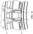
FIG. 9 is a detailed cross section view of a portion ofFIG. 8 in accordance with an embodiment of the present invention. -
FIG. 10 is a perspective view of a combustion liner in accordance with an embodiment of the present invention. -
FIG. 11 is a detailed perspective view of a portion of the combustion liner ofFIG. 10 in accordance with an embodiment of the present invention. -
FIG. 12 is a detailed top elevation view of a portion of the combustion liner ofFIG. 10 in accordance with an embodiment of the present invention. - The preferred embodiment of the present invention will now be described in detail with specific reference to
FIGS. 7-12 . Referring now toFIG. 7 , acombustion liner 700 for use in a low emissionsgas turbine combustor 750 is depicted. Referring toFIG. 10 , thecombustion liner 700 is generally cylindrical in shape and has aninner wall 702, anouter wall 704 separated from theinner wall 702 by a liner wall thickness. To compensate for elevated operating temperatures of the combustion liner, a portion of theinner wall 702 can be coated with a thermal barrier coating generally comprising a bond coating and a ceramic top coating. - The
combustion liner 700 also has aninlet end 706 and an opposing outlet end 708. Located along theouter wall 704 of the combustion liner, and extending radially outward, is a plurality of raisedsurfaces 710. The raisedsurfaces 710, which are more clearly shown inFIGS. 10-12 , provide an increase in the total surface area of theouter wall 704 so as to enhance the available surface area of the combustion liner available to be cooled by the compressed air passing along theouter wall 704. An increase in the overall surface area capable of being cooled improves the heat transfer across the thickness of thecombustion liner 700. As one skilled in the art understands, the raisedsurfaces 710 also serve to "trip" the passing airflow or disturb the airflow pattern in order to improve cooling effectiveness. The size and shape of the raisedsurfaces 710 can vary depending on the cooling requirements for thecombustion liner 700. For the embodiment of the present invention shown inFIGS. 10-12 , the raisedsurfaces 710 are generally triangular in shape such that the radially outermost point of the raisedsurface 710 has a diameter greater than theouter wall 704. However, the raisedsurfaces 710 can be of alternate shapes including circular, square or rectangular. The raised surfaces extend along a length of thecombustion liner 700 requiring maximum cooling efficiency. - The
combustion liner 700 also comprises a plurality ofsupport tab assemblies 712. Thesupport tab assemblies 712, which are shown in more detail inFIG. 8 , are circular, square or rectangular. The raised surfaces extend along a length of thecombustion liner 700 requiring maximum cooling efficiency. - The
combustion liner 700 also comprises a plurality ofsupport tab assemblies 712. Thesupport tab assemblies 712, which are shown in more detail inFIG. 8 , are positioned about theouter wall 704 of thecombustion liner 700. Each of the support tab assemblies include twoparallel liner tabs 714, spaced a tangential distance apart, secured to theouter wall 704 and extend radially outward from theouter wall 704. Preferably, threesupport tab assemblies 712 are spaced at approximately 120 degree intervals around theouter wall 704 of thecombustion liner 700. - As depicted in
FIG. 10 , the plurality of raisedsurfaces 710 extends along a majority of the axial length of thecombustion liner 700. However, as shown inFIGS. 11 and 12 , in the area of thecombustion liner 700 of thesupport tab assemblies 712, the plurality of raised surfaces is interrupted to create asmooth region 705 of theouter wall 704, or a region of the combustion liner outer wall that is free from the raised surfaces 710. - The combustion liner provides a location for the combustion process to occur. A
combustion zone 752 is located within thecombustion liner 700, thereby heating the surrounding portion of thecombustion liner 700. Due to the geometry of thegas turbine combustor 750 it is necessary to locate the support tab assemblies 712 a distance axially downstream from theinlet end 706 such that thesupport tab assemblies 712 are radially outward of thecombustion zone 752. As such, thesupport tab assemblies 712 are subjected to higher operating temperatures than liner tabs of the prior art. Therefore, because of their elevated operating temperatures, it is necessary to minimize any heat sink associated withsupport tab assemblies 712 or other structures capable of absorbing the heat, and resulting thermal stresses, from thecombustion zone 752. - As discussed above, the
support tab assemblies 712 comprise a pair ofparallel liner tabs 714. Theliner tabs 714 extend radially outward from theouter wall 704 of thecombustion liner 700, where each of theliner tabs 714 have an axial length L, a radial height H, and a thickness T and are secured to the combustion liner. For the embodiment of the present invention depicted inFIGS. 10-12 , the axial length L of the tab is greater than the radial height H and the height H is greater than the thickness T. Theliner tabs 714 are secured to theouter wall 704 of thecombustion liner 700 by a means such as welding and forming a full penetration weld joint 716. Since theliner tabs 714 are secured to theouter wall 704, it is preferred that theliner tabs 714 be fabricated from a material comparable to a liner tab can be welded into a pocket in the liner, such that the machined plate forms part of the liner wall, instead of resting on top of the liner wall as in the prior art ofFIGS. 1-4 . Alternate means of securing the liner tabs, such as brazing, can be used in lieu of welding. - The
liner tabs 714 are generally parallel and spaced apart by a liner tab gap G. The specific gap may vary depending on the specific design requirements of the combustion liner and flow sleeve, but for the embodiment depicted inFIGS. 10-12 , the gap G betweenliner tabs 714 is approximately 1.27 cm (0.5 inches). By placing a gap G between theliner tabs 714, compressed air is permitted to flow between the liner tabs thereby providing cooling air to all sides of theliner tabs 714. - Referring back to
FIGS. 8 and9 , the engagement of thecombustion liner 700 in aflow sleeve 701 is shown. Each of theliner tabs 714 are located within slots formed inpegs 703 of theflow sleeve 701. Thepegs 703 provide a fixed location in which the liner is installed and ensures proper axial positioning of thecombustion liner 700 within the gas turbine combustor. Because the material of the flow sleeve is generally harder than thecombustion liner tabs 714, the liner tabs tend to become worn. To prevent wear to thecombustion liner tabs 714, the flow sleeve slots are coated with a wear coating that is softer than theliner tabs 714, such that any wear that does occur at this interface occurs to the wear coating. - As discussed above, each of the
liner tabs 714 has an axial length, a radial height and a thickness. While the specific size and shape of theliner tab 714 will vary depending on the combustor design, it is important to note that the thickness T of theliner tabs 714 for the embodiment disclosed inFIGS. 7-12 is thinner than the single T-shaped liner tab of the prior art. Through various testing and analysis, it has been determined that the use of multiple, but thinner, liner tabs, provides an advantage over the prior art in terms of reduced thermal stresses due to disconnecting the adjacent tabs and the thinner liner tabs forming less of a heat sink and smaller thermal gradient. Furthermore, with theliner tabs 714 secured directly to the liner, they generate a minimal "footprint" on the combustion liner, compared to prior art designs, such as the T-shaped lug inFIGS 1-4 . More specifically, by only securing the liner tabs to the liner, and not a T-shaped plate, there is less material to absorb heat from the combustion liner. The present invention incorporates other stress-reducing design features such as chamfered edges, fillet radii, and improved flexibility to further reduce stresses. For example, utilizing theliner tab 714 of the present invention over the liner tab 402 has shown a reduction in maximum concentrated stress upwards of approximately 40%. - In addition to the flexibility and improved heat transfer capability, utilizing
multiple liner tabs 714 provides a stronger combustion liner support because of the multiple contact points with the mating flow sleeve. Also, themultiple liner tabs 714 provides for a corresponding increase in wear surfaces when engaged with theflow sleeve peg 703. As one skilled in the art understands, when theliner tabs 714 are engaged in the flow sleeve and the combustor is operational, the combustion liner is subjected to high levels of vibrations. As such, thecombustion liner tabs 714 vibrate within the flow sleeve pegs 703, typically resulting in wear to theliner tabs 714. Therefore, providing additional surfaces capable of sustaining the wear reduces any concentrated wear experienced by liner tabs of the prior art. - While the invention has been described in what is known as presently the preferred embodiment, it is to be understood that the invention is not to be limited to the disclosed embodiment but, on the contrary, is intended to cover various modifications and equivalent arrangements within the scope of the following claims. The present invention has been described in relation to particular embodiments, which are intended in all respects to be illustrative rather than restrictive. Alternative embodiments and required operations, such as machining of shroud faces other than the hardface surfaces and operation-induced wear of the hardfaces, will become apparent to those of ordinary skill in the art to which the present invention pertains without departing from its scope.
Claims (13)
- A generally cylindrical combustion liner (700) retention system comprising a combustion liner (700) including:an inner wall (702);an outer wall (704) separated from the inner wall (702) by a liner wall thickness;an inlet end (706);an outlet end (708) opposite the inlet end (706); anda plurality of support tab assemblies (712) positioned about the outer wall (704), each of the support tab assemblies (712) including two parallel liner tabs (714) extending radially outward from the outer wall (704), anda flow sleeve (110) positioned around the combustion liner (700), characterized in that, the flow sleeve (110) includes pegs (703) with slots,wherein the pegs (703) and the liner tabs (714) are configured and
located to enable the location of the liner tabs (714) in the slots by providing a fixed location in which the liner is installed and ensuring proper axial positioning of the combustion liner (700). - The combustion liner (700) of claim 1, wherein the outer wall (704) further comprises a plurality of raised surfaces (710) extending radially outward from the outer wall (704) where the plurality of raised surfaces (710) provide increased surface area for improving heat transfer across the liner wall thickness.
- The combustion liner (700) (700) of claim 2, wherein the plurality of support tab assemblies (712) are positioned radially outward of the combustion zone (752) in the combustion liner (700) and create a region (705) of the combustion liner (700) free from the plurality of raised surfaces (710) on the outer wall (704).
- The combustion liner (700) of claim 1, wherein the inner wall (702) further comprises a thermal barrier coating.
- The combustion liner (700) of claim 1, wherein the parallel liner tabs (714) are welded or brazed to the liner (700) outer wall (704).
- The combustion liner (700) of claim 1, wherein the support tab assemblies (712) are fabricated from a material compatible with the combustion liner (700).
- The combustion liner (700) of claim 1, wherein the liner tabs (714) are fabricated from a material similar to that of the combustion liner (700).
- The combustion liner (700) of claim 7, wherein the axial length (L) of the liner tab (714) is greater than the height (H) of the liner tab (714) and the height (H) of the liner tab (714) is greater than the thickness (T) of the liner tab (714), and the liner tab gap (G) between parallel liner tabs (714) is approximately 1.27 cm (0.5 inches).
- A method of reducing of thermal stresses at an interface between a combustion liner (700) and a liner support assembly (712), including the steps of:securing a plurality of liner support assemblies (712) to an outer wall (704) of the combustion liner (700) at equally spaced intervals, with each of the liner support assemblies (712) comprising two parallel liner tabs (714) oriented to extend radially outward from the outer wall (704) yet be separated by a tangential gap (G); andlocating the liner tabs (714) in slots formed in pegs (703) formed in flow sleeve (701) positioned around the combustion liner (700).
- The method of claim 9, wherein the securing of the liner support assemblies (712) occurs by welding or brazing a base of the liner tab (714) to the outer wall (704) of the combustion liner (700).
- The method of claim 9, wherein the liner tabs (714) extend through an opening in the liner wall, and are positioned an axial distance along the outer wall (704) of the combustion liner (700) from an inlet end (706) such that the liner tabs (714) are located radially outward of a combustion zone (752).
- The method of claim 9, wherein the sets of parallel liner tabs (714) are equally spaced at approximately 120 degree intervals about the outer wall (704) of the combustion liner (700).
- The method of claim 9, wherein cooling air passes along the outer wall (704) of the liner (700) and between the liner tabs (714).
Applications Claiming Priority (3)
| Application Number | Priority Date | Filing Date | Title |
|---|---|---|---|
| US201261708323P | 2012-10-01 | 2012-10-01 | |
| US14/038,038 US9897317B2 (en) | 2012-10-01 | 2013-09-26 | Thermally free liner retention mechanism |
| PCT/US2013/062680 WO2014099091A2 (en) | 2012-10-01 | 2013-09-30 | Thermally free liner retention mechanism |
Publications (2)
| Publication Number | Publication Date |
|---|---|
| EP2904323A2 EP2904323A2 (en) | 2015-08-12 |
| EP2904323B1 true EP2904323B1 (en) | 2017-01-25 |
Family
ID=50483464
Family Applications (1)
| Application Number | Title | Priority Date | Filing Date |
|---|---|---|---|
| EP13846255.1A Active EP2904323B1 (en) | 2012-10-01 | 2013-09-30 | Thermally free liner retention mechanism |
Country Status (9)
| Country | Link |
|---|---|
| US (1) | US9897317B2 (en) |
| EP (1) | EP2904323B1 (en) |
| JP (1) | JP6316302B2 (en) |
| KR (1) | KR102145173B1 (en) |
| CN (1) | CN104685296B (en) |
| CA (1) | CA2885288C (en) |
| MX (1) | MX355345B (en) |
| SA (1) | SA515360209B1 (en) |
| WO (1) | WO2014099091A2 (en) |
Families Citing this family (7)
| Publication number | Priority date | Publication date | Assignee | Title |
|---|---|---|---|---|
| US10060630B2 (en) | 2012-10-01 | 2018-08-28 | Ansaldo Energia Ip Uk Limited | Flamesheet combustor contoured liner |
| US9347669B2 (en) | 2012-10-01 | 2016-05-24 | Alstom Technology Ltd. | Variable length combustor dome extension for improved operability |
| US10378456B2 (en) | 2012-10-01 | 2019-08-13 | Ansaldo Energia Switzerland AG | Method of operating a multi-stage flamesheet combustor |
| KR102405991B1 (en) * | 2014-11-21 | 2022-06-10 | 에이치2 아이피 유케이 리미티드 | Flamesheet combustor contoured liner |
| US11377970B2 (en) | 2018-11-02 | 2022-07-05 | Chromalloy Gas Turbine Llc | System and method for providing compressed air to a gas turbine combustor |
| US11248797B2 (en) * | 2018-11-02 | 2022-02-15 | Chromalloy Gas Turbine Llc | Axial stop configuration for a combustion liner |
| CN112628010A (en) * | 2020-12-14 | 2021-04-09 | 大连海事大学 | Single-cylinder diesel engine cylinder sleeve temperature field control device and method |
Family Cites Families (66)
| Publication number | Priority date | Publication date | Assignee | Title |
|---|---|---|---|---|
| US2457157A (en) | 1946-07-30 | 1948-12-28 | Westinghouse Electric Corp | Turbine apparatus |
| US3759038A (en) * | 1971-12-09 | 1973-09-18 | Westinghouse Electric Corp | Self aligning combustor and transition structure for a gas turbine |
| US4292810A (en) | 1979-02-01 | 1981-10-06 | Westinghouse Electric Corp. | Gas turbine combustion chamber |
| US4735052A (en) | 1985-09-30 | 1988-04-05 | Kabushiki Kaisha Toshiba | Gas turbine apparatus |
| US4910957A (en) | 1988-07-13 | 1990-03-27 | Prutech Ii | Staged lean premix low nox hot wall gas turbine combustor with improved turndown capability |
| US4928481A (en) | 1988-07-13 | 1990-05-29 | Prutech Ii | Staged low NOx premix gas turbine combustor |
| JP2544470B2 (en) | 1989-02-03 | 1996-10-16 | 株式会社日立製作所 | Gas turbine combustor and operating method thereof |
| IL93630A0 (en) | 1989-03-27 | 1990-12-23 | Gen Electric | Flameholder for gas turbine engine afterburner |
| GB9023004D0 (en) | 1990-10-23 | 1990-12-05 | Rolls Royce Plc | A gas turbine engine combustion chamber and a method of operating a gas turbine engine combustion chamber |
| US5363643A (en) * | 1993-02-08 | 1994-11-15 | General Electric Company | Segmented combustor |
| US5676538A (en) | 1993-06-28 | 1997-10-14 | General Electric Company | Fuel nozzle for low-NOx combustor burners |
| US5452574A (en) | 1994-01-14 | 1995-09-26 | Solar Turbines Incorporated | Gas turbine engine catalytic and primary combustor arrangement having selective air flow control |
| JP2950720B2 (en) | 1994-02-24 | 1999-09-20 | 株式会社東芝 | Gas turbine combustion device and combustion control method therefor |
| DE4416650A1 (en) | 1994-05-11 | 1995-11-16 | Abb Management Ag | Combustion process for atmospheric combustion plants |
| DE69625744T2 (en) | 1995-06-05 | 2003-10-16 | Rolls-Royce Corp., Indianapolis | Lean premix burner with low NOx emissions for industrial gas turbines |
| WO1999006767A1 (en) | 1997-07-31 | 1999-02-11 | Siemens Aktiengesellschaft | Burner |
| US5983642A (en) | 1997-10-13 | 1999-11-16 | Siemens Westinghouse Power Corporation | Combustor with two stage primary fuel tube with concentric members and flow regulating |
| EP0931979A1 (en) | 1998-01-23 | 1999-07-28 | DVGW Deutscher Verein des Gas- und Wasserfaches -Technisch-wissenschaftliche Vereinigung- | Method and apparatus for supressing flame and pressure fluctuations in a furnace |
| US6199371B1 (en) * | 1998-10-15 | 2001-03-13 | United Technologies Corporation | Thermally compliant liner |
| JP3364169B2 (en) | 1999-06-09 | 2003-01-08 | 三菱重工業株式会社 | Gas turbine and its combustor |
| GB0019533D0 (en) | 2000-08-10 | 2000-09-27 | Rolls Royce Plc | A combustion chamber |
| DE10056124A1 (en) | 2000-11-13 | 2002-05-23 | Alstom Switzerland Ltd | Burner system with staged fuel injection and method of operation |
| US7093445B2 (en) | 2002-05-31 | 2006-08-22 | Catalytica Energy Systems, Inc. | Fuel-air premixing system for a catalytic combustor |
| US6915636B2 (en) | 2002-07-15 | 2005-07-12 | Power Systems Mfg., Llc | Dual fuel fin mixer secondary fuel nozzle |
| EP1413831A1 (en) * | 2002-10-21 | 2004-04-28 | Siemens Aktiengesellschaft | Annular combustor for a gas turbine and gas turbine |
| US6807803B2 (en) * | 2002-12-06 | 2004-10-26 | General Electric Company | Gas turbine exhaust diffuser |
| US6935116B2 (en) | 2003-04-28 | 2005-08-30 | Power Systems Mfg., Llc | Flamesheet combustor |
| US6986254B2 (en) | 2003-05-14 | 2006-01-17 | Power Systems Mfg, Llc | Method of operating a flamesheet combustor |
| US7373778B2 (en) * | 2004-08-26 | 2008-05-20 | General Electric Company | Combustor cooling with angled segmented surfaces |
| GB2420614B (en) * | 2004-11-30 | 2009-06-03 | Alstom Technology Ltd | Tile and exo-skeleton tile structure |
| US7308793B2 (en) | 2005-01-07 | 2007-12-18 | Power Systems Mfg., Llc | Apparatus and method for reducing carbon monoxide emissions |
| US7237384B2 (en) | 2005-01-26 | 2007-07-03 | Peter Stuttaford | Counter swirl shear mixer |
| US7677025B2 (en) | 2005-02-01 | 2010-03-16 | Power Systems Mfg., Llc | Self-purging pilot fuel injection system |
| US7386980B2 (en) | 2005-02-02 | 2008-06-17 | Power Systems Mfg., Llc | Combustion liner with enhanced heat transfer |
| US7137256B1 (en) | 2005-02-28 | 2006-11-21 | Peter Stuttaford | Method of operating a combustion system for increased turndown capability |
| US7513115B2 (en) | 2005-05-23 | 2009-04-07 | Power Systems Mfg., Llc | Flashback suppression system for a gas turbine combustor |
| JP2007113888A (en) | 2005-10-24 | 2007-05-10 | Kawasaki Heavy Ind Ltd | Gas turbine engine combustor structure |
| US7770395B2 (en) | 2006-02-27 | 2010-08-10 | Mitsubishi Heavy Industries, Ltd. | Combustor |
| US7540152B2 (en) | 2006-02-27 | 2009-06-02 | Mitsubishi Heavy Industries, Ltd. | Combustor |
| US20080083224A1 (en) | 2006-10-05 | 2008-04-10 | Balachandar Varatharajan | Method and apparatus for reducing gas turbine engine emissions |
| US7886545B2 (en) | 2007-04-27 | 2011-02-15 | General Electric Company | Methods and systems to facilitate reducing NOx emissions in combustion systems |
| US7762075B2 (en) | 2007-08-14 | 2010-07-27 | General Electric Company | Combustion liner stop in a gas turbine |
| US20090111063A1 (en) | 2007-10-29 | 2009-04-30 | General Electric Company | Lean premixed, radial inflow, multi-annular staged nozzle, can-annular, dual-fuel combustor |
| EP2107309A1 (en) | 2008-04-01 | 2009-10-07 | Siemens Aktiengesellschaft | Quarls in a burner |
| JP5172468B2 (en) | 2008-05-23 | 2013-03-27 | 川崎重工業株式会社 | Combustion device and control method of combustion device |
| CH699309A1 (en) * | 2008-08-14 | 2010-02-15 | Alstom Technology Ltd | Thermal machine with air cooled, annular combustion chamber. |
| US20100192587A1 (en) * | 2009-02-03 | 2010-08-05 | William Kirk Hessler | Combustor assembly for use in a gas turbine engine and method of assembling same |
| JP4797079B2 (en) | 2009-03-13 | 2011-10-19 | 川崎重工業株式会社 | Gas turbine combustor |
| US20100300107A1 (en) * | 2009-05-29 | 2010-12-02 | General Electric Company | Method and flow sleeve profile reduction to extend combustor liner life |
| US8336312B2 (en) | 2009-06-17 | 2012-12-25 | Siemens Energy, Inc. | Attenuation of combustion dynamics using a Herschel-Quincke filter |
| US8387393B2 (en) | 2009-06-23 | 2013-03-05 | Siemens Energy, Inc. | Flashback resistant fuel injection system |
| US20100326079A1 (en) | 2009-06-25 | 2010-12-30 | Baifang Zuo | Method and system to reduce vane swirl angle in a gas turbine engine |
| WO2011018853A1 (en) | 2009-08-13 | 2011-02-17 | 三菱重工業株式会社 | Combustor |
| US8991192B2 (en) | 2009-09-24 | 2015-03-31 | Siemens Energy, Inc. | Fuel nozzle assembly for use as structural support for a duct structure in a combustor of a gas turbine engine |
| EP2325542B1 (en) | 2009-11-18 | 2013-03-20 | Siemens Aktiengesellschaft | Swirler vane, swirler and burner assembly |
| JP5084847B2 (en) | 2010-01-13 | 2012-11-28 | 株式会社日立製作所 | Gas turbine combustor |
| US8646277B2 (en) * | 2010-02-19 | 2014-02-11 | General Electric Company | Combustor liner for a turbine engine with venturi and air deflector |
| US8769955B2 (en) | 2010-06-02 | 2014-07-08 | Siemens Energy, Inc. | Self-regulating fuel staging port for turbine combustor |
| JP5156066B2 (en) | 2010-08-27 | 2013-03-06 | 株式会社日立製作所 | Gas turbine combustor |
| US20120186269A1 (en) * | 2011-01-25 | 2012-07-26 | General Electric Company | Support between transition piece and impingement sleeve in combustor |
| US8973368B2 (en) | 2011-01-26 | 2015-03-10 | United Technologies Corporation | Mixer assembly for a gas turbine engine |
| US8448444B2 (en) * | 2011-02-18 | 2013-05-28 | General Electric Company | Method and apparatus for mounting transition piece in combustor |
| US9182122B2 (en) * | 2011-10-05 | 2015-11-10 | General Electric Company | Combustor and method for supplying flow to a combustor |
| US20150184858A1 (en) | 2012-10-01 | 2015-07-02 | Peter John Stuttford | Method of operating a multi-stage flamesheet combustor |
| US10060630B2 (en) | 2012-10-01 | 2018-08-28 | Ansaldo Energia Ip Uk Limited | Flamesheet combustor contoured liner |
| US9347669B2 (en) | 2012-10-01 | 2016-05-24 | Alstom Technology Ltd. | Variable length combustor dome extension for improved operability |
-
2013
- 2013-09-26 US US14/038,038 patent/US9897317B2/en active Active
- 2013-09-30 CN CN201380051300.6A patent/CN104685296B/en active Active
- 2013-09-30 JP JP2015535722A patent/JP6316302B2/en active Active
- 2013-09-30 KR KR1020157011137A patent/KR102145173B1/en active Active
- 2013-09-30 EP EP13846255.1A patent/EP2904323B1/en active Active
- 2013-09-30 MX MX2015003100A patent/MX355345B/en active IP Right Grant
- 2013-09-30 CA CA2885288A patent/CA2885288C/en active Active
- 2013-09-30 WO PCT/US2013/062680 patent/WO2014099091A2/en not_active Ceased
-
2015
- 2015-03-30 SA SA515360209A patent/SA515360209B1/en unknown
Non-Patent Citations (1)
| Title |
|---|
| None * |
Also Published As
| Publication number | Publication date |
|---|---|
| US20150184856A1 (en) | 2015-07-02 |
| JP2015534623A (en) | 2015-12-03 |
| CN104685296A (en) | 2015-06-03 |
| WO2014099091A3 (en) | 2014-08-28 |
| KR102145173B1 (en) | 2020-08-18 |
| SA515360209B1 (en) | 2017-05-11 |
| EP2904323A2 (en) | 2015-08-12 |
| KR20150063505A (en) | 2015-06-09 |
| JP6316302B2 (en) | 2018-04-25 |
| CA2885288A1 (en) | 2014-06-26 |
| CA2885288C (en) | 2021-06-01 |
| WO2014099091A2 (en) | 2014-06-26 |
| US9897317B2 (en) | 2018-02-20 |
| MX355345B (en) | 2018-04-16 |
| CN104685296B (en) | 2017-07-21 |
| MX2015003100A (en) | 2015-09-21 |
Similar Documents
| Publication | Publication Date | Title |
|---|---|---|
| US9383104B2 (en) | Continuous combustion liner for a combustor of a gas turbine | |
| US9897317B2 (en) | Thermally free liner retention mechanism | |
| CN104781610B (en) | fuel nozzle heat shield | |
| CA2802062C (en) | Combustor for gas turbine engine | |
| EP3220047B1 (en) | Gas turbine flow sleeve mounting | |
| US20140260277A1 (en) | Flow sleeve for a combustion module of a gas turbine | |
| US9243508B2 (en) | System and method for recirculating a hot gas flowing through a gas turbine | |
| JP2005061823A (en) | Combustor dome assembly of a gas turbine engine having an improved deflector plate | |
| US10451278B2 (en) | Combustion chamber having axially extending and annular coolant manifolds | |
| US20170268783A1 (en) | Axially staged fuel injector assembly mounting | |
| KR20210148971A (en) | Combustion liner cooling | |
| EP2230456A2 (en) | Combustion liner with mixing hole stub | |
| JP5718796B2 (en) | Gas turbine combustor with sealing member | |
| EP2626520A2 (en) | Turbine shell having a plate frame heat exchanger | |
| EP3220048B1 (en) | Combustion liner cooling |
Legal Events
| Date | Code | Title | Description |
|---|---|---|---|
| PUAI | Public reference made under article 153(3) epc to a published international application that has entered the european phase |
Free format text: ORIGINAL CODE: 0009012 |
|
| 17P | Request for examination filed |
Effective date: 20150424 |
|
| AK | Designated contracting states |
Kind code of ref document: A2 Designated state(s): AL AT BE BG CH CY CZ DE DK EE ES FI FR GB GR HR HU IE IS IT LI LT LU LV MC MK MT NL NO PL PT RO RS SE SI SK SM TR |
|
| AX | Request for extension of the european patent |
Extension state: BA ME |
|
| DAX | Request for extension of the european patent (deleted) | ||
| GRAP | Despatch of communication of intention to grant a patent |
Free format text: ORIGINAL CODE: EPIDOSNIGR1 |
|
| RAP1 | Party data changed (applicant data changed or rights of an application transferred) |
Owner name: GENERAL ELECTRIC TECHNOLOGY GMBH |
|
| INTG | Intention to grant announced |
Effective date: 20160810 |
|
| GRAS | Grant fee paid |
Free format text: ORIGINAL CODE: EPIDOSNIGR3 |
|
| GRAA | (expected) grant |
Free format text: ORIGINAL CODE: 0009210 |
|
| AK | Designated contracting states |
Kind code of ref document: B1 Designated state(s): AL AT BE BG CH CY CZ DE DK EE ES FI FR GB GR HR HU IE IS IT LI LT LU LV MC MK MT NL NO PL PT RO RS SE SI SK SM TR |
|
| REG | Reference to a national code |
Ref country code: GB Ref legal event code: FG4D |
|
| REG | Reference to a national code |
Ref country code: CH Ref legal event code: EP |
|
| REG | Reference to a national code |
Ref country code: AT Ref legal event code: REF Ref document number: 864371 Country of ref document: AT Kind code of ref document: T Effective date: 20170215 |
|
| REG | Reference to a national code |
Ref country code: IE Ref legal event code: FG4D |
|
| REG | Reference to a national code |
Ref country code: DE Ref legal event code: R096 Ref document number: 602013016878 Country of ref document: DE |
|
| REG | Reference to a national code |
Ref country code: NL Ref legal event code: FP |
|
| REG | Reference to a national code |
Ref country code: CH Ref legal event code: NV Representative=s name: RENTSCH PARTNER AG, CH Ref country code: CH Ref legal event code: PUE Owner name: ANSALDO ENERGIA IP UK LIMITED, GB Free format text: FORMER OWNER: GENERAL ELECTRIC TECHNOLOGY GMBH, CH |
|
| REG | Reference to a national code |
Ref country code: LT Ref legal event code: MG4D |
|
| RAP2 | Party data changed (patent owner data changed or rights of a patent transferred) |
Owner name: ANSALDO ENERGIA IP UK LIMITED |
|
| REG | Reference to a national code |
Ref country code: AT Ref legal event code: MK05 Ref document number: 864371 Country of ref document: AT Kind code of ref document: T Effective date: 20170125 |
|
| PG25 | Lapsed in a contracting state [announced via postgrant information from national office to epo] |
Ref country code: NO Free format text: LAPSE BECAUSE OF FAILURE TO SUBMIT A TRANSLATION OF THE DESCRIPTION OR TO PAY THE FEE WITHIN THE PRESCRIBED TIME-LIMIT Effective date: 20170425 Ref country code: GR Free format text: LAPSE BECAUSE OF FAILURE TO SUBMIT A TRANSLATION OF THE DESCRIPTION OR TO PAY THE FEE WITHIN THE PRESCRIBED TIME-LIMIT Effective date: 20170426 Ref country code: HR Free format text: LAPSE BECAUSE OF FAILURE TO SUBMIT A TRANSLATION OF THE DESCRIPTION OR TO PAY THE FEE WITHIN THE PRESCRIBED TIME-LIMIT Effective date: 20170125 Ref country code: FI Free format text: LAPSE BECAUSE OF FAILURE TO SUBMIT A TRANSLATION OF THE DESCRIPTION OR TO PAY THE FEE WITHIN THE PRESCRIBED TIME-LIMIT Effective date: 20170125 Ref country code: IS Free format text: LAPSE BECAUSE OF FAILURE TO SUBMIT A TRANSLATION OF THE DESCRIPTION OR TO PAY THE FEE WITHIN THE PRESCRIBED TIME-LIMIT Effective date: 20170525 Ref country code: LT Free format text: LAPSE BECAUSE OF FAILURE TO SUBMIT A TRANSLATION OF THE DESCRIPTION OR TO PAY THE FEE WITHIN THE PRESCRIBED TIME-LIMIT Effective date: 20170125 |
|
| PG25 | Lapsed in a contracting state [announced via postgrant information from national office to epo] |
Ref country code: SE Free format text: LAPSE BECAUSE OF FAILURE TO SUBMIT A TRANSLATION OF THE DESCRIPTION OR TO PAY THE FEE WITHIN THE PRESCRIBED TIME-LIMIT Effective date: 20170125 Ref country code: AT Free format text: LAPSE BECAUSE OF FAILURE TO SUBMIT A TRANSLATION OF THE DESCRIPTION OR TO PAY THE FEE WITHIN THE PRESCRIBED TIME-LIMIT Effective date: 20170125 Ref country code: RS Free format text: LAPSE BECAUSE OF FAILURE TO SUBMIT A TRANSLATION OF THE DESCRIPTION OR TO PAY THE FEE WITHIN THE PRESCRIBED TIME-LIMIT Effective date: 20170125 Ref country code: PT Free format text: LAPSE BECAUSE OF FAILURE TO SUBMIT A TRANSLATION OF THE DESCRIPTION OR TO PAY THE FEE WITHIN THE PRESCRIBED TIME-LIMIT Effective date: 20170525 Ref country code: PL Free format text: LAPSE BECAUSE OF FAILURE TO SUBMIT A TRANSLATION OF THE DESCRIPTION OR TO PAY THE FEE WITHIN THE PRESCRIBED TIME-LIMIT Effective date: 20170125 Ref country code: ES Free format text: LAPSE BECAUSE OF FAILURE TO SUBMIT A TRANSLATION OF THE DESCRIPTION OR TO PAY THE FEE WITHIN THE PRESCRIBED TIME-LIMIT Effective date: 20170125 Ref country code: LV Free format text: LAPSE BECAUSE OF FAILURE TO SUBMIT A TRANSLATION OF THE DESCRIPTION OR TO PAY THE FEE WITHIN THE PRESCRIBED TIME-LIMIT Effective date: 20170125 Ref country code: BG Free format text: LAPSE BECAUSE OF FAILURE TO SUBMIT A TRANSLATION OF THE DESCRIPTION OR TO PAY THE FEE WITHIN THE PRESCRIBED TIME-LIMIT Effective date: 20170425 |
|
| REG | Reference to a national code |
Ref country code: FR Ref legal event code: PLFP Year of fee payment: 5 |
|
| REG | Reference to a national code |
Ref country code: CH Ref legal event code: PCAR Free format text: NEW ADDRESS: BELLERIVESTRASSE 203 POSTFACH, 8034 ZUERICH (CH) |
|
| REG | Reference to a national code |
Ref country code: DE Ref legal event code: R097 Ref document number: 602013016878 Country of ref document: DE |
|
| PG25 | Lapsed in a contracting state [announced via postgrant information from national office to epo] |
Ref country code: CZ Free format text: LAPSE BECAUSE OF FAILURE TO SUBMIT A TRANSLATION OF THE DESCRIPTION OR TO PAY THE FEE WITHIN THE PRESCRIBED TIME-LIMIT Effective date: 20170125 Ref country code: SK Free format text: LAPSE BECAUSE OF FAILURE TO SUBMIT A TRANSLATION OF THE DESCRIPTION OR TO PAY THE FEE WITHIN THE PRESCRIBED TIME-LIMIT Effective date: 20170125 Ref country code: RO Free format text: LAPSE BECAUSE OF FAILURE TO SUBMIT A TRANSLATION OF THE DESCRIPTION OR TO PAY THE FEE WITHIN THE PRESCRIBED TIME-LIMIT Effective date: 20170125 Ref country code: EE Free format text: LAPSE BECAUSE OF FAILURE TO SUBMIT A TRANSLATION OF THE DESCRIPTION OR TO PAY THE FEE WITHIN THE PRESCRIBED TIME-LIMIT Effective date: 20170125 |
|
| PGFP | Annual fee paid to national office [announced via postgrant information from national office to epo] |
Ref country code: CH Payment date: 20170921 Year of fee payment: 5 |
|
| PG25 | Lapsed in a contracting state [announced via postgrant information from national office to epo] |
Ref country code: SM Free format text: LAPSE BECAUSE OF FAILURE TO SUBMIT A TRANSLATION OF THE DESCRIPTION OR TO PAY THE FEE WITHIN THE PRESCRIBED TIME-LIMIT Effective date: 20170125 Ref country code: DK Free format text: LAPSE BECAUSE OF FAILURE TO SUBMIT A TRANSLATION OF THE DESCRIPTION OR TO PAY THE FEE WITHIN THE PRESCRIBED TIME-LIMIT Effective date: 20170125 |
|
| PLBE | No opposition filed within time limit |
Free format text: ORIGINAL CODE: 0009261 |
|
| STAA | Information on the status of an ep patent application or granted ep patent |
Free format text: STATUS: NO OPPOSITION FILED WITHIN TIME LIMIT |
|
| 26N | No opposition filed |
Effective date: 20171026 |
|
| PG25 | Lapsed in a contracting state [announced via postgrant information from national office to epo] |
Ref country code: SI Free format text: LAPSE BECAUSE OF FAILURE TO SUBMIT A TRANSLATION OF THE DESCRIPTION OR TO PAY THE FEE WITHIN THE PRESCRIBED TIME-LIMIT Effective date: 20170125 |
|
| GBPC | Gb: european patent ceased through non-payment of renewal fee |
Effective date: 20170930 |
|
| PG25 | Lapsed in a contracting state [announced via postgrant information from national office to epo] |
Ref country code: MC Free format text: LAPSE BECAUSE OF FAILURE TO SUBMIT A TRANSLATION OF THE DESCRIPTION OR TO PAY THE FEE WITHIN THE PRESCRIBED TIME-LIMIT Effective date: 20170125 |
|
| REG | Reference to a national code |
Ref country code: IE Ref legal event code: MM4A |
|
| REG | Reference to a national code |
Ref country code: BE Ref legal event code: MM Effective date: 20170930 |
|
| PG25 | Lapsed in a contracting state [announced via postgrant information from national office to epo] |
Ref country code: LU Free format text: LAPSE BECAUSE OF NON-PAYMENT OF DUE FEES Effective date: 20170930 |
|
| PG25 | Lapsed in a contracting state [announced via postgrant information from national office to epo] |
Ref country code: IE Free format text: LAPSE BECAUSE OF NON-PAYMENT OF DUE FEES Effective date: 20170930 Ref country code: GB Free format text: LAPSE BECAUSE OF NON-PAYMENT OF DUE FEES Effective date: 20170930 |
|
| PG25 | Lapsed in a contracting state [announced via postgrant information from national office to epo] |
Ref country code: BE Free format text: LAPSE BECAUSE OF NON-PAYMENT OF DUE FEES Effective date: 20170930 |
|
| REG | Reference to a national code |
Ref country code: FR Ref legal event code: PLFP Year of fee payment: 6 |
|
| PG25 | Lapsed in a contracting state [announced via postgrant information from national office to epo] |
Ref country code: MT Free format text: LAPSE BECAUSE OF NON-PAYMENT OF DUE FEES Effective date: 20170930 |
|
| REG | Reference to a national code |
Ref country code: CH Ref legal event code: PL |
|
| PG25 | Lapsed in a contracting state [announced via postgrant information from national office to epo] |
Ref country code: HU Free format text: LAPSE BECAUSE OF FAILURE TO SUBMIT A TRANSLATION OF THE DESCRIPTION OR TO PAY THE FEE WITHIN THE PRESCRIBED TIME-LIMIT; INVALID AB INITIO Effective date: 20130930 |
|
| REG | Reference to a national code |
Ref country code: NL Ref legal event code: PD Owner name: ANSALDO ENERGIA IP UK LIMITED; GB Free format text: DETAILS ASSIGNMENT: CHANGE OF OWNER(S), ASSIGNMENT; FORMER OWNER NAME: GENERAL ELECTRIC TECHNOLOGY GMBH Effective date: 20190724 |
|
| PG25 | Lapsed in a contracting state [announced via postgrant information from national office to epo] |
Ref country code: LI Free format text: LAPSE BECAUSE OF NON-PAYMENT OF DUE FEES Effective date: 20180930 Ref country code: CH Free format text: LAPSE BECAUSE OF NON-PAYMENT OF DUE FEES Effective date: 20180930 |
|
| PG25 | Lapsed in a contracting state [announced via postgrant information from national office to epo] |
Ref country code: CY Free format text: LAPSE BECAUSE OF FAILURE TO SUBMIT A TRANSLATION OF THE DESCRIPTION OR TO PAY THE FEE WITHIN THE PRESCRIBED TIME-LIMIT Effective date: 20170125 |
|
| PG25 | Lapsed in a contracting state [announced via postgrant information from national office to epo] |
Ref country code: MK Free format text: LAPSE BECAUSE OF FAILURE TO SUBMIT A TRANSLATION OF THE DESCRIPTION OR TO PAY THE FEE WITHIN THE PRESCRIBED TIME-LIMIT Effective date: 20170125 |
|
| REG | Reference to a national code |
Ref country code: DE Ref legal event code: R082 Ref document number: 602013016878 Country of ref document: DE Representative=s name: DREISS PATENTANWAELTE PARTG MBB, DE Ref country code: DE Ref legal event code: R081 Ref document number: 602013016878 Country of ref document: DE Owner name: ANSALDO ENERGIA IP UK LIMITED, GB Free format text: FORMER OWNER: GENERAL ELECTRIC TECHNOLOGY GMBH, BADEN, CH Ref country code: DE Ref legal event code: R081 Ref document number: 602013016878 Country of ref document: DE Owner name: H2 IP UK LIMITED, GB Free format text: FORMER OWNER: GENERAL ELECTRIC TECHNOLOGY GMBH, BADEN, CH |
|
| PG25 | Lapsed in a contracting state [announced via postgrant information from national office to epo] |
Ref country code: TR Free format text: LAPSE BECAUSE OF FAILURE TO SUBMIT A TRANSLATION OF THE DESCRIPTION OR TO PAY THE FEE WITHIN THE PRESCRIBED TIME-LIMIT Effective date: 20170125 |
|
| PG25 | Lapsed in a contracting state [announced via postgrant information from national office to epo] |
Ref country code: AL Free format text: LAPSE BECAUSE OF FAILURE TO SUBMIT A TRANSLATION OF THE DESCRIPTION OR TO PAY THE FEE WITHIN THE PRESCRIBED TIME-LIMIT Effective date: 20170125 |
|
| REG | Reference to a national code |
Ref country code: DE Ref legal event code: R082 Ref document number: 602013016878 Country of ref document: DE Representative=s name: DREISS PATENTANWAELTE PARTG MBB, DE Ref country code: DE Ref legal event code: R081 Ref document number: 602013016878 Country of ref document: DE Owner name: H2 IP UK LIMITED, GB Free format text: FORMER OWNER: ANSALDO ENERGIA IP UK LIMITED, LONDON, GB |
|
| REG | Reference to a national code |
Ref country code: NL Ref legal event code: PD Owner name: H2 IP UK LIMITED; GB Free format text: DETAILS ASSIGNMENT: CHANGE OF OWNER(S), ASSIGNMENT; FORMER OWNER NAME: GENERAL ELECTRIC TECHNOLOGY GMBH Effective date: 20210621 |
|
| PGFP | Annual fee paid to national office [announced via postgrant information from national office to epo] |
Ref country code: NL Payment date: 20250704 Year of fee payment: 13 |
|
| PGFP | Annual fee paid to national office [announced via postgrant information from national office to epo] |
Ref country code: DE Payment date: 20250805 Year of fee payment: 13 |
|
| PGFP | Annual fee paid to national office [announced via postgrant information from national office to epo] |
Ref country code: IT Payment date: 20250825 Year of fee payment: 13 |
|
| PGFP | Annual fee paid to national office [announced via postgrant information from national office to epo] |
Ref country code: FR Payment date: 20250808 Year of fee payment: 13 |