EP2904279B1 - A refrigeration reciprocating compressor including bearing arrangements - Google Patents
A refrigeration reciprocating compressor including bearing arrangements Download PDFInfo
- Publication number
- EP2904279B1 EP2904279B1 EP13780305.2A EP13780305A EP2904279B1 EP 2904279 B1 EP2904279 B1 EP 2904279B1 EP 13780305 A EP13780305 A EP 13780305A EP 2904279 B1 EP2904279 B1 EP 2904279B1
- Authority
- EP
- European Patent Office
- Prior art keywords
- end portion
- crankshaft
- bushing
- reciprocating compressor
- bearing
- Prior art date
- Legal status (The legal status is an assumption and is not a legal conclusion. Google has not performed a legal analysis and makes no representation as to the accuracy of the status listed.)
- Active
Links
Images



Classifications
-
- F—MECHANICAL ENGINEERING; LIGHTING; HEATING; WEAPONS; BLASTING
- F16—ENGINEERING ELEMENTS AND UNITS; GENERAL MEASURES FOR PRODUCING AND MAINTAINING EFFECTIVE FUNCTIONING OF MACHINES OR INSTALLATIONS; THERMAL INSULATION IN GENERAL
- F16C—SHAFTS; FLEXIBLE SHAFTS; ELEMENTS OR CRANKSHAFT MECHANISMS; ROTARY BODIES OTHER THAN GEARING ELEMENTS; BEARINGS
- F16C25/00—Bearings for exclusively rotary movement adjustable for wear or play
- F16C25/02—Sliding-contact bearings
- F16C25/04—Sliding-contact bearings self-adjusting
-
- F—MECHANICAL ENGINEERING; LIGHTING; HEATING; WEAPONS; BLASTING
- F04—POSITIVE - DISPLACEMENT MACHINES FOR LIQUIDS; PUMPS FOR LIQUIDS OR ELASTIC FLUIDS
- F04B—POSITIVE-DISPLACEMENT MACHINES FOR LIQUIDS; PUMPS
- F04B39/00—Component parts, details, or accessories, of pumps or pumping systems specially adapted for elastic fluids, not otherwise provided for in, or of interest apart from, groups F04B25/00 - F04B37/00
- F04B39/0094—Component parts, details, or accessories, of pumps or pumping systems specially adapted for elastic fluids, not otherwise provided for in, or of interest apart from, groups F04B25/00 - F04B37/00 crankshaft
-
- F—MECHANICAL ENGINEERING; LIGHTING; HEATING; WEAPONS; BLASTING
- F04—POSITIVE - DISPLACEMENT MACHINES FOR LIQUIDS; PUMPS FOR LIQUIDS OR ELASTIC FLUIDS
- F04B—POSITIVE-DISPLACEMENT MACHINES FOR LIQUIDS; PUMPS
- F04B9/00—Piston machines or pumps characterised by the driving or driven means to or from their working members
- F04B9/02—Piston machines or pumps characterised by the driving or driven means to or from their working members the means being mechanical
- F04B9/04—Piston machines or pumps characterised by the driving or driven means to or from their working members the means being mechanical the means being cams, eccentrics or pin-and-slot mechanisms
- F04B9/045—Piston machines or pumps characterised by the driving or driven means to or from their working members the means being mechanical the means being cams, eccentrics or pin-and-slot mechanisms the means being eccentrics
-
- F—MECHANICAL ENGINEERING; LIGHTING; HEATING; WEAPONS; BLASTING
- F16—ENGINEERING ELEMENTS AND UNITS; GENERAL MEASURES FOR PRODUCING AND MAINTAINING EFFECTIVE FUNCTIONING OF MACHINES OR INSTALLATIONS; THERMAL INSULATION IN GENERAL
- F16C—SHAFTS; FLEXIBLE SHAFTS; ELEMENTS OR CRANKSHAFT MECHANISMS; ROTARY BODIES OTHER THAN GEARING ELEMENTS; BEARINGS
- F16C3/00—Shafts; Axles; Cranks; Eccentrics
- F16C3/04—Crankshafts, eccentric-shafts; Cranks, eccentrics
- F16C3/22—Cranks; Eccentrics
-
- F—MECHANICAL ENGINEERING; LIGHTING; HEATING; WEAPONS; BLASTING
- F16—ENGINEERING ELEMENTS AND UNITS; GENERAL MEASURES FOR PRODUCING AND MAINTAINING EFFECTIVE FUNCTIONING OF MACHINES OR INSTALLATIONS; THERMAL INSULATION IN GENERAL
- F16C—SHAFTS; FLEXIBLE SHAFTS; ELEMENTS OR CRANKSHAFT MECHANISMS; ROTARY BODIES OTHER THAN GEARING ELEMENTS; BEARINGS
- F16C33/00—Parts of bearings; Special methods for making bearings or parts thereof
- F16C33/02—Parts of sliding-contact bearings
- F16C33/04—Brasses; Bushes; Linings
- F16C33/06—Sliding surface mainly made of metal
- F16C33/10—Construction relative to lubrication
-
- F—MECHANICAL ENGINEERING; LIGHTING; HEATING; WEAPONS; BLASTING
- F16—ENGINEERING ELEMENTS AND UNITS; GENERAL MEASURES FOR PRODUCING AND MAINTAINING EFFECTIVE FUNCTIONING OF MACHINES OR INSTALLATIONS; THERMAL INSULATION IN GENERAL
- F16C—SHAFTS; FLEXIBLE SHAFTS; ELEMENTS OR CRANKSHAFT MECHANISMS; ROTARY BODIES OTHER THAN GEARING ELEMENTS; BEARINGS
- F16C33/00—Parts of bearings; Special methods for making bearings or parts thereof
- F16C33/02—Parts of sliding-contact bearings
- F16C33/04—Brasses; Bushes; Linings
- F16C33/06—Sliding surface mainly made of metal
- F16C33/10—Construction relative to lubrication
- F16C33/1025—Construction relative to lubrication with liquid, e.g. oil, as lubricant
-
- F—MECHANICAL ENGINEERING; LIGHTING; HEATING; WEAPONS; BLASTING
- F16—ENGINEERING ELEMENTS AND UNITS; GENERAL MEASURES FOR PRODUCING AND MAINTAINING EFFECTIVE FUNCTIONING OF MACHINES OR INSTALLATIONS; THERMAL INSULATION IN GENERAL
- F16C—SHAFTS; FLEXIBLE SHAFTS; ELEMENTS OR CRANKSHAFT MECHANISMS; ROTARY BODIES OTHER THAN GEARING ELEMENTS; BEARINGS
- F16C33/00—Parts of bearings; Special methods for making bearings or parts thereof
- F16C33/02—Parts of sliding-contact bearings
- F16C33/04—Brasses; Bushes; Linings
- F16C33/06—Sliding surface mainly made of metal
- F16C33/10—Construction relative to lubrication
- F16C33/1025—Construction relative to lubrication with liquid, e.g. oil, as lubricant
- F16C33/106—Details of distribution or circulation inside the bearings, e.g. details of the bearing surfaces to affect flow or pressure of the liquid
-
- F—MECHANICAL ENGINEERING; LIGHTING; HEATING; WEAPONS; BLASTING
- F16—ENGINEERING ELEMENTS AND UNITS; GENERAL MEASURES FOR PRODUCING AND MAINTAINING EFFECTIVE FUNCTIONING OF MACHINES OR INSTALLATIONS; THERMAL INSULATION IN GENERAL
- F16C—SHAFTS; FLEXIBLE SHAFTS; ELEMENTS OR CRANKSHAFT MECHANISMS; ROTARY BODIES OTHER THAN GEARING ELEMENTS; BEARINGS
- F16C33/00—Parts of bearings; Special methods for making bearings or parts thereof
- F16C33/02—Parts of sliding-contact bearings
- F16C33/04—Brasses; Bushes; Linings
- F16C33/06—Sliding surface mainly made of metal
- F16C33/12—Structural composition; Use of special materials or surface treatments, e.g. for rust-proofing
- F16C33/121—Use of special materials
-
- F—MECHANICAL ENGINEERING; LIGHTING; HEATING; WEAPONS; BLASTING
- F16—ENGINEERING ELEMENTS AND UNITS; GENERAL MEASURES FOR PRODUCING AND MAINTAINING EFFECTIVE FUNCTIONING OF MACHINES OR INSTALLATIONS; THERMAL INSULATION IN GENERAL
- F16C—SHAFTS; FLEXIBLE SHAFTS; ELEMENTS OR CRANKSHAFT MECHANISMS; ROTARY BODIES OTHER THAN GEARING ELEMENTS; BEARINGS
- F16C33/00—Parts of bearings; Special methods for making bearings or parts thereof
- F16C33/02—Parts of sliding-contact bearings
- F16C33/04—Brasses; Bushes; Linings
- F16C33/06—Sliding surface mainly made of metal
- F16C33/12—Structural composition; Use of special materials or surface treatments, e.g. for rust-proofing
- F16C33/122—Multilayer structures of sleeves, washers or liners
- F16C33/125—Details of bearing layers, i.e. the lining
-
- F—MECHANICAL ENGINEERING; LIGHTING; HEATING; WEAPONS; BLASTING
- F16—ENGINEERING ELEMENTS AND UNITS; GENERAL MEASURES FOR PRODUCING AND MAINTAINING EFFECTIVE FUNCTIONING OF MACHINES OR INSTALLATIONS; THERMAL INSULATION IN GENERAL
- F16C—SHAFTS; FLEXIBLE SHAFTS; ELEMENTS OR CRANKSHAFT MECHANISMS; ROTARY BODIES OTHER THAN GEARING ELEMENTS; BEARINGS
- F16C33/00—Parts of bearings; Special methods for making bearings or parts thereof
- F16C33/02—Parts of sliding-contact bearings
- F16C33/04—Brasses; Bushes; Linings
- F16C33/06—Sliding surface mainly made of metal
- F16C33/12—Structural composition; Use of special materials or surface treatments, e.g. for rust-proofing
- F16C33/128—Porous bearings, e.g. bushes of sintered alloy
-
- F—MECHANICAL ENGINEERING; LIGHTING; HEATING; WEAPONS; BLASTING
- F16—ENGINEERING ELEMENTS AND UNITS; GENERAL MEASURES FOR PRODUCING AND MAINTAINING EFFECTIVE FUNCTIONING OF MACHINES OR INSTALLATIONS; THERMAL INSULATION IN GENERAL
- F16C—SHAFTS; FLEXIBLE SHAFTS; ELEMENTS OR CRANKSHAFT MECHANISMS; ROTARY BODIES OTHER THAN GEARING ELEMENTS; BEARINGS
- F16C33/00—Parts of bearings; Special methods for making bearings or parts thereof
- F16C33/02—Parts of sliding-contact bearings
- F16C33/04—Brasses; Bushes; Linings
- F16C33/20—Sliding surface consisting mainly of plastics
-
- F—MECHANICAL ENGINEERING; LIGHTING; HEATING; WEAPONS; BLASTING
- F16—ENGINEERING ELEMENTS AND UNITS; GENERAL MEASURES FOR PRODUCING AND MAINTAINING EFFECTIVE FUNCTIONING OF MACHINES OR INSTALLATIONS; THERMAL INSULATION IN GENERAL
- F16C—SHAFTS; FLEXIBLE SHAFTS; ELEMENTS OR CRANKSHAFT MECHANISMS; ROTARY BODIES OTHER THAN GEARING ELEMENTS; BEARINGS
- F16C33/00—Parts of bearings; Special methods for making bearings or parts thereof
- F16C33/02—Parts of sliding-contact bearings
- F16C33/04—Brasses; Bushes; Linings
- F16C33/20—Sliding surface consisting mainly of plastics
- F16C33/203—Multilayer structures, e.g. sleeves comprising a plastic lining
- F16C33/205—Multilayer structures, e.g. sleeves comprising a plastic lining with two layers
-
- F—MECHANICAL ENGINEERING; LIGHTING; HEATING; WEAPONS; BLASTING
- F16—ENGINEERING ELEMENTS AND UNITS; GENERAL MEASURES FOR PRODUCING AND MAINTAINING EFFECTIVE FUNCTIONING OF MACHINES OR INSTALLATIONS; THERMAL INSULATION IN GENERAL
- F16C—SHAFTS; FLEXIBLE SHAFTS; ELEMENTS OR CRANKSHAFT MECHANISMS; ROTARY BODIES OTHER THAN GEARING ELEMENTS; BEARINGS
- F16C9/00—Bearings for crankshafts or connecting-rods; Attachment of connecting-rods
- F16C9/02—Crankshaft bearings
-
- F—MECHANICAL ENGINEERING; LIGHTING; HEATING; WEAPONS; BLASTING
- F16—ENGINEERING ELEMENTS AND UNITS; GENERAL MEASURES FOR PRODUCING AND MAINTAINING EFFECTIVE FUNCTIONING OF MACHINES OR INSTALLATIONS; THERMAL INSULATION IN GENERAL
- F16C—SHAFTS; FLEXIBLE SHAFTS; ELEMENTS OR CRANKSHAFT MECHANISMS; ROTARY BODIES OTHER THAN GEARING ELEMENTS; BEARINGS
- F16C9/00—Bearings for crankshafts or connecting-rods; Attachment of connecting-rods
- F16C9/02—Crankshaft bearings
- F16C9/03—Arrangements for adjusting play
-
- F—MECHANICAL ENGINEERING; LIGHTING; HEATING; WEAPONS; BLASTING
- F16—ENGINEERING ELEMENTS AND UNITS; GENERAL MEASURES FOR PRODUCING AND MAINTAINING EFFECTIVE FUNCTIONING OF MACHINES OR INSTALLATIONS; THERMAL INSULATION IN GENERAL
- F16C—SHAFTS; FLEXIBLE SHAFTS; ELEMENTS OR CRANKSHAFT MECHANISMS; ROTARY BODIES OTHER THAN GEARING ELEMENTS; BEARINGS
- F16C2208/00—Plastics; Synthetic resins, e.g. rubbers
- F16C2208/20—Thermoplastic resins
-
- F—MECHANICAL ENGINEERING; LIGHTING; HEATING; WEAPONS; BLASTING
- F16—ENGINEERING ELEMENTS AND UNITS; GENERAL MEASURES FOR PRODUCING AND MAINTAINING EFFECTIVE FUNCTIONING OF MACHINES OR INSTALLATIONS; THERMAL INSULATION IN GENERAL
- F16C—SHAFTS; FLEXIBLE SHAFTS; ELEMENTS OR CRANKSHAFT MECHANISMS; ROTARY BODIES OTHER THAN GEARING ELEMENTS; BEARINGS
- F16C2208/00—Plastics; Synthetic resins, e.g. rubbers
- F16C2208/20—Thermoplastic resins
- F16C2208/58—Several materials as provided for in F16C2208/30 - F16C2208/54 mentioned as option
-
- F—MECHANICAL ENGINEERING; LIGHTING; HEATING; WEAPONS; BLASTING
- F16—ENGINEERING ELEMENTS AND UNITS; GENERAL MEASURES FOR PRODUCING AND MAINTAINING EFFECTIVE FUNCTIONING OF MACHINES OR INSTALLATIONS; THERMAL INSULATION IN GENERAL
- F16C—SHAFTS; FLEXIBLE SHAFTS; ELEMENTS OR CRANKSHAFT MECHANISMS; ROTARY BODIES OTHER THAN GEARING ELEMENTS; BEARINGS
- F16C2223/00—Surface treatments; Hardening; Coating
- F16C2223/30—Coating surfaces
- F16C2223/60—Coating surfaces by vapour deposition, e.g. PVD, CVD
-
- F—MECHANICAL ENGINEERING; LIGHTING; HEATING; WEAPONS; BLASTING
- F16—ENGINEERING ELEMENTS AND UNITS; GENERAL MEASURES FOR PRODUCING AND MAINTAINING EFFECTIVE FUNCTIONING OF MACHINES OR INSTALLATIONS; THERMAL INSULATION IN GENERAL
- F16C—SHAFTS; FLEXIBLE SHAFTS; ELEMENTS OR CRANKSHAFT MECHANISMS; ROTARY BODIES OTHER THAN GEARING ELEMENTS; BEARINGS
- F16C3/00—Shafts; Axles; Cranks; Eccentrics
- F16C3/04—Crankshafts, eccentric-shafts; Cranks, eccentrics
- F16C3/06—Crankshafts
- F16C3/08—Crankshafts made in one piece
-
- F—MECHANICAL ENGINEERING; LIGHTING; HEATING; WEAPONS; BLASTING
- F16—ENGINEERING ELEMENTS AND UNITS; GENERAL MEASURES FOR PRODUCING AND MAINTAINING EFFECTIVE FUNCTIONING OF MACHINES OR INSTALLATIONS; THERMAL INSULATION IN GENERAL
- F16C—SHAFTS; FLEXIBLE SHAFTS; ELEMENTS OR CRANKSHAFT MECHANISMS; ROTARY BODIES OTHER THAN GEARING ELEMENTS; BEARINGS
- F16C3/00—Shafts; Axles; Cranks; Eccentrics
- F16C3/04—Crankshafts, eccentric-shafts; Cranks, eccentrics
- F16C3/06—Crankshafts
- F16C3/14—Features relating to lubrication
Definitions
- the present invention refers to a refrigeration reciprocating compressor including bearing arrangements of the type which comprises: a crankcase carrying a cylinder and a bearing hub defining a radial bearing, a crankshaft mounted in the radial bearing and having an eccentric end portion and a free end portion which project outwards from a first and second end portions, respectively, of the bearing hub, a piston housed in the cylinder and a connecting rod coupling the eccentric end portion of the crankshaft to the piston, wherein the first end portion of the bearing hub is defined by a bushing extension affixed in the interior of the bearing hub and presenting an end portion which projects axially.
- FIG. 1 of the enclosed drawings A conventional construction for a refrigeration compressor of the reciprocating type is illustrated in figure 1 of the enclosed drawings and comprises, in the interior of a shell (not illustrated), a crankcase 10 which carries a cylinder 20, inside which reciprocates a piston 30.
- the crankcase 10 is also provided with a bearing hub 40 which defines, internally, a radial bearing 41 in which is mounted a crankshaft 50 which incorporates an eccentric end portion 55, projecting outwardly from a first end portion 40a of the bearing hub 40 and operatively coupled to the piston 30, by means of a connecting rod 60, and a free end portion 56 which projects outwardly from a second end portion 40b of the bearing hub 40.
- crankshaft 50 Around the eccentric end portion 55 of the crankshaft 50 is mounted a larger eye 61 of the connecting rod 60, whose smaller eye 62 is coupled to the piston 30, by a piston pin 63.
- the free end portion 56 of the crankshaft 50 which projects outwards from the bearing hub 40, is coupled to a rotor 71 of an electric motor 70, having a stator 72 attached to the crankcase 10.
- the rotor 71 of the electric motor 70 rotates the crankshaft 50, impelling the piston 30, by means of the connecting rod 60, in a reciprocating movement.
- valve plate (not illustrated), provided with at least one suction valve and a discharge valve, according to any adequate construction known in the prior art or not.
- a first problem related to these compressors results from the process employed to carry out the machining operations in the crankcase 10, in order to form the cylinder 20 and the radial bearing 41, in the crankshaft 50 and also in the eyes of the connecting rod 60. Regardless of the economically feasible type of said process, position errors will always occur, in greater or lesser extent, such as those which cause loss of orthogonality between the axis of the crankshaft 50 and the axis of the piston 30 of the mounted assembly.
- the positioning errors mentioned above are responsible for localized contacts between the piston 30 and the cylinder 20, between the piston pin 63 and the smaller eye 62 of the connecting rod 60, between the larger eye 61 of the connecting rod 60 and the eccentric portion 55 of the crankshaft 50, and also between the latter and the radial bearing 41 machined in the bearing hub 40 of the crankcase 10.
- a second problematic feature is due to the fact that, during compression of the gas in the cylinder 20, the compression force F, which actuates against the top of the piston 30, is transmitted to the connecting rod 60 and to the eccentric portion 55 of the crankshaft 50, generating deformations in the mechanical assembly, which cause the misalignment of the eccentric portion 55 of the crankshaft 50 in relation to the axis of the larger eye 61 of the connecting rod 60, and of the crankshaft 50 in relation to the axis of the radial bearing 41, increasing the problems of localized contacts mentioned above which result from position errors in the manufacture and assembly of the component parts, and producing wear and high energy consumption.
- the first end portion 40a and, in a much lesser extent, the second end portion 40b of the bearing hub 40 are those in which the radial bearing 41 supports the load and the moments imposed to the bearing hub 40, which causes the same wear problems by localized contact and high energy consumption mentioned above.
- a third aspect to be considered in these compressors is related to the stator 72, when it presents concentricity deviations in relation to the radial bearing 41 of the bearing hub 40, and also to the rotor 71 when it presents radial errors in its positioning.
- the stator 72 When the starts of the electric motor 70, presenting said deviations and errors, magnetic radial forces on the rotor 71 are produced, causing localized wear in the radial bearing 41, in the second end portion 40b of the bearing hub 40.
- the highest contact forces, between the crankshaft 50 and the second end portion 40b of the bearing hub 40 require a higher torque from the motor 70 to start the movement, that is, a higher motor power, thus increasing the minimum starting voltage.
- the first end portion of the bearing hub may present a certain compliance, and may be radially and elastically deformed by the localized pressure exerted by the confronting region of the crankshaft, at the final phase of the compression stroke of the piston, in order to accommodate to the surface of the crankshaft, avoiding a punctual contact and the interruption of the thick oil film between the crankshaft and the bearing hub in the first end portion of the latter.
- said previous construction provides a compliant region in the bearing hub 40, it deals only with the interruption of the oil film in the first end portion 40a of the bearing hub 40, on which are applied, by the crankshaft 50, the highest forces derived from the compression of the refrigerant gas by the piston.
- the compliance (elastic deformation) of the first end portion 40a of the bearing hub 40 is not able to eliminate, neither the problem of the accentuated wear in said end portion of the larger eye 61 of the connecting rod 60, nor the transmission, by the latter, of forces on the piston 30, forcing it radially against the cylinder 20.
- Another aspect not considered by said previous construction is the increase of torque of the electric motor 70, and the wear by localized contact in the second end portion 40b of the bearing hub 40, at starts of the electric motor 70 with the rotor 71 presenting concentricity deviations in relation to the stator 72.
- Said previous construction is only directed to the maintenance of the oil film in the radial bearings of a refrigeration reciprocating compressor, considering only the problem of the lubrication deficiency and accentuated wear in the first end portion 40a of the bearing hub 40.
- the prior art requires additional machining and finishing operations in the crankcase 10, for forming the region which is capable to present the compliance, and also for forming the end radial bearing extensions to be defined in the bearing hub 40. It should also be observed that the formation of the compliant region and of the radial bearing regions directly in the crankcase 10 is also costly, requiring precise dimensional adjustments in the machining and finishing operations for each type of compressor, making difficult to use variations of the usual cylindrical shape of the radial bearing regions in the bearing hub 40.
- the present invention has the object of providing a refrigeration reciprocating compressor, including bearing arrangements, of the type discussed above, which allow simplifying the provision of bearing regions and avoiding, or at least reducing, the wear, by localized contact, of the radial bearing regions of the crankshaft in relation to the end portions of the bearing hub.
- the present invention has the object of avoiding, or at least reducing, said wear, compensating, at least partially, for the coaxiality deviations of the crankshaft in relation to the radial bearing in the bearing hub, and which are generally caused by geometric deviations during manufacture and assembly of said movable cooperating parts, by the compression forces of the refrigerant gas, or also by the magnetic radial forces of the rotor of the electric motor, particularly at the start of the latter.
- An additional and complementary object of the present invention is to provide bearing arrangements in a refrigeration compressor as mentioned above, which allow simplifying the provision of bearing regions and avoiding, or at least reducing, the wear, by localized contact, of the radial bearing regions of the crankshaft in relation to the larger eye of the connecting rod, avoiding, or at least reducing, said wear, by compensating, at least partially, for the coaxiality deviations of the crankshaft in relation to the larger eye of the connecting rod.
- bearing arrangements in a refrigeration reciprocating compressor of the type mentioned at the beginning in which the end portions of the bearing hub are each defined by a respective bushing extension affixed in the interior of the bearing hub, and presenting an end portion, which projects axially outwards from the bearing hub, so as to be elastically and radially deformed outwardly when pressed by a confronting portion of the crankshaft which presents a coaxiality deviation of its axis in relation to the axis of the radial bearing.
- the end portion of the larger eye of the connecting rod, turned to the crankcase is defined by a bushing extension fixed in the interior of the larger eye and presenting an end portion, which projects axially outwards from the larger eye, so as to be elastically and radially deformed outwardly when pressed by a confronting portion of the eccentric end portion of the crankshaft, which presents a coaxiality deviation of its axis in relation to the axis of the larger eye.
- the construction proposed by the present invention allows substantially improving the bearing conditions, not only of the crankshaft, but also of its eccentric end portion, in the bearing hub and in the larger eye of the connecting rod, respectively, thus reducing localized wear, efficiency loss, and avoiding the increase of the starting torque in the operation of the compressor.
- the radial bearing regions are allowed to undergo a controlled deformation, so as to compensate, at least in part, for the deviations in the nominal relative positioning of the cooperating parts, caused by misalignments in the manufacture or assembly of said cooperating parts, or by forces acting thereon and resulting from the operation of the electric motor of the compressor or from compression of the refrigerant gas.
- any of said end portions of the bearing hub and of the large eye of the connecting rod, with reduced thickness can be easily obtained without using special machining in the crankcase, in the case of the bearing hub, and without using special geometries in the process of compressing the connecting rod produced by sintering, by using bushing extensions fixed in the interior of the bearing hub and of the larger eye.
- the elastic radial deformation of said end portions with reduced thickness may occur due to the direct contact of the two surfaces, or by force transfer through a field of distributed pressures generated in the oil film and which separates, totally or partially, the two surfaces, an effect known as elastohydrodynamic lubrication.
- a refrigeration compressor of the type which comprises, in the interior of a shell (not illustrated), a crankcase 10 defining, generally in a single cast piece, a cylinder 20 having an axis Z, and a bearing hub 40 which defines, internally, a radial bearing 41 having an axis X1.
- a crankshaft 50 having an axis Y1 is mounted in the interior of the radial bearing 41 of the bearing hub 40 and has an eccentric end portion 55, with an axis Y2 projecting outwards from a first end portion 40a of the bearing hub 40, and a free end portion 56 which projects outwards from a second end portion 40b of the bearing hub 40.
- a piston 30 is housed in the cylinder 20, so as to be displaced therein, in a reciprocating movement, by a connecting rod 60 which has an end defining a larger eye 61, mounted around the eccentric end portion 55 of the crankshaft 50, and an opposite end carrying a coupling means 62 to allow coupling the connecting rod 60 to the piston 30.
- the coupling means 62 can take the form of a smaller eye 62a, of a spherical joint (not illustrated), or any other means capable of carrying out the connecting rod-piston coupling.
- the smaller eye 62a is coupled to the piston 30, by means of a piston pin 63, the crankshaft 50 being rotatively driven by an electric motor 70 which comprises a rotor 71, mounted to the free end portion 56 of the crankshaft 50, and a stator 72 attached to the crankcase 10, around the rotor 71.
- an electric motor 70 which comprises a rotor 71, mounted to the free end portion 56 of the crankshaft 50, and a stator 72 attached to the crankcase 10, around the rotor 71.
- piston pin 63 and the smaller eye 62a of the connecting rod 60 can be replaced by a piston-connecting rod assembly having a spherical joint, or any other coupling arrangement, without departing from the constructive concept of the present invention.
- crankcase 10 and crankshaft 50 may be constructed in any adequate well known prior art material as, for example, aluminum or cast iron alloys for the crankcase 10, and steel or cast iron alloys for the crankshaft 50.
- figure 3 does not illustrate the cylinder, the piston, part of the connecting rod and the electric motor, it should be understood that such parts were suppressed only for purposes of simplification of said figure, since they are already part of the type of compressor to which the present bearing arrangements are applied.
- the axis Y1 of the crankshaft 50 coincides with the axis X1 of the radial bearing 41 of the bearing hub 40, and the axis X2 of the larger eye 61 of the connecting rod 60 coincides with the axis Y2 of the eccentric end portion 55 of the crankshaft 50.
- the axes Y1 and Y2 of the crankshaft 50 and of its eccentric end portion 55 are orthogonal to the axis Z of the cylinder 20.
- the positioning error of the crankshaft 50 and of its eccentric end portion 55, in the interior of the radial bearing 41 and of the larger eye 61 of the connecting rod 60, respectively, causes the crankshaft 50 to have circumferential portions of its surface with small dimensions, in the axial and circumferential directions, seated only on end circumferential regions, with small axial and circumferential dimensions, of the first and second end portions 40a, 40b of the bearing hub 40, and of the end portion 61a of the larger eye 61 of the connecting rod 60, since these mutual contact regions or practically punctual bearing regions, under positioning error of the crankshaft, do not accommodate to the angular misalignment of the crankshaft in relation to the part of the radial bearing which supports said crankshaft.
- the provision of a compliant region in the first end portion 40a of the bearing hub 40 does not address the issue regarding the increase of torque of the electric motor 70 and the wear by localized contact in the second end portion 40b of the bearing hub 40, at starts of the electric motor 70, with the rotor 71 presenting concentricity deviations in relation to the stator 72.
- the localized wear produced by the operational condition of "inclination" of the crankshaft 50, is high and it is also responsible for the loss of efficiency due to the rupture of the oil film in said bearing regions with a reduced area, often requiring the use of high viscosity oil or bearings with higher load capacity, which tends to increase the losses by viscous friction.
- the first and second end portions 40a, 40b of the bearing hub 40 are each defined by a respective bushing extension 45, 46, fixed in the interior of the bearing hub 40 and presenting an end portion 45a, 46a, which projects axially outwards from the bearing hub 40, so as to be elastically and radially deformed outwardly when pressed by a confronting portion of the crankshaft 50, when the latter presents a coaxiality deviation of its axis Y1 in relation to the axis X1 of the radial bearing 41.
- the dimensioning of the radial thickness and axial extension of said end portions 45a, 46a of the bushing extensions 45, 46 is made so as to allow for a desired radial deformation of said end portions 45a, 46a, which is necessary and sufficient to minimize or completely eliminate the mutual contact regions of the crankshaft 50 with the radial bearing 41, in the positioning error condition of the crankshaft 50 already mentioned above.
- each of the end portions 45a, 46a of the bushing extensions 45, 46 defines, with a confronting part of the crankshaft 50 and in the elastically deformed condition, a confronting region CR of surfaces having dimensions, in the axial and circumferential directions, which are capable of maintaining, in said regions, an oil film which separates, at least partially, the surfaces which form said the confronting region (CR) of surfaces.
- the compliant regions, in the end portions of the bearing hub 40, allow that the radial deformation of the bushing extensions 45, 46 produces a confronting region CR of surfaces, whose axial and circumferential dimensions are increased from a nominal condition of linear tangency between said parts, to a support condition provided by axial and circumferential extensions sufficient to avoid interruption of the oil film.
- the confronting region CR of surfaces of the deformed end portion 45a, between the crankshaft 50 and the bushing extension 45, in the first end portion 40a of the bearing hub 40 takes a nearly semi-elliptical form, with its end edge coinciding with the marginal edge of the adjacent end portion 45a of the respective bushing extension 45. It should be understood that the confronting region of surfaces, between the crankshaft 50 and the bushing extension 46, in the second end portion 40b of the bearing hub 40, present, according to the present invention, the same configuration illustrated in figures 5 and 6 .
- the invention produces a confronting region CR of surfaces, between the crankshaft 50 and the bushing extensions 45, 46 of the radial bearing 41, in the first and second end portions 40a, 40b of the bearing hub 40, take a nearly semi-elliptical form, with its end edge coinciding with the marginal edge of the adjacent end portion 45a, 46a of the respective bushing extension 45, 46.
- the solution proposed by the invention allows increasing the effective bearing area between said relatively moving parts of crankshaft 50 and of radial bearing defined by the bushing extensions 45, 46, from a condition of tangential contact in pieces, assumed as rigid, according to a circumferential arc line, to a condition in which said contact occurs according to the confronting region CR of surfaces, which is increased in the axial and circumferential directions.
- the dimensions, in the axial and circumferential directions, of said elastically deformable end portions, are determined by the design characteristics of the compressor, the size and operational conditions of the compressor, and by the dimensional tolerances permitted in the manufacturing and assembly processes.
- crankcase 10 As being usually produced in a cast metal alloy, its internal conformation for receiving and retaining the bushing extensions 45, 46 may be made by machining the crankcase 10. As illustrated in figures 2 and 3 , the crankcase 10 has its end region, from which projects the eccentric end portion 55 of the crankshaft 50, machined for forming a recess 11 around the radial bearing 41, within which is housed an axial bearing 80, to support the weight of the crankshaft 50 and of the rotor 71 and which may present any adequate construction, such as a roller or a sliding bearing.
- end portion 45a, 46a of the bushing extension 45, 46 may present the same radial thickness of the remainder of the bushing extension 45, 46, it is possible to provide the end portions 45a, 46a projecting axially outwards from the bearing hub 40, with the radial thickness reduced in relation to the largest diameter thereof, when the radial thickness required for the bushing extensions 45, 46 is greater than that necessary to provide, to their respective end portions 45a, 46a, the desired capacity of elastic deformation, when pressed by a confronting portion of the crankshaft 50, which presents a coaxiality deviation of its axis in relation to the axis of the respective part of radial bearing 41.
- said reduced thickness may be constant or variable, depending on the design characteristics of the compressor.
- the bearing hub 40 may be internally provided with an inner median circumferential projection 48, configured to define a stop for the bushing extensions 45, 46.
- the first and second end portions 40a, 40b of the bearing hub 40 may be defined by respective bushing extensions 45, 46 formed in a single tubular piece with a longitudinal extension compatible with the longitudinal extension of the bearing hub 40.
- bushing extensions 45, 46 favors the use of materials other than cast or sintered iron, aluminum or nickel alloys, such as, for example, polymeric materials, iron or nickel alloys with self-lubricating properties, and special coatings which are economically feasible, since said materials may have localized applications in said components.
- the bushing extensions 45, 46 are formed in a single material which, as mentioned above, may be iron alloys, aluminum or nickel alloys, or polymeric materials.
- the material is defined in metal alloys, particularly iron or nickel alloys, it may be formed so as to present self-lubricating characteristics defined, for example, by the dispersion of non-metallic solid lubricant material in the metallic matrix.
- the bushing extensions 45, 46 may also be formed in a single material defined by an engineering polymer, adequately dimensioned to operate as a radial bearing and also to define the axial projections external to the bearing hub, which are responsible for defining the compliant regions upon occurrence of coaxiality deviation between the crankshaft 50 and the axis X1 of the radial bearing 41.
- the dimensioning of the radial thickness and of the axial extension of said end portions 45a, 46a is made as previously mentioned, to allow for the desired radial deformation of said end portions 45a, 46a in the positioning error condition of the crankshaft 50.
- the bushing extensions 45, 46 when formed in metal alloys, can receive a surface treatment for reducing wear, such as nitriding, and/or for reducing the friction coefficient, such as diamondlike carbon deposition (DLC-Diamond Like Carbon) or other material by physical deposition (PVD-Physical Vapour Deposition).
- a surface treatment for reducing wear such as nitriding
- reducing the friction coefficient such as diamondlike carbon deposition (DLC-Diamond Like Carbon) or other material by physical deposition (PVD-Physical Vapour Deposition).
- the bushing extensions may also be constructed in more than one material such as, for example, a material comprising an inner anti-friction layer AF, obtained in a polymeric material such as, for example, PTFE (polytetrafluorethylene), which is housed and retained within a jacket S, in a metallic material and to be equally affixed inside the bearing hub 40, as schematically illustrated in figures 4 and 5 .
- a material comprising an inner anti-friction layer AF obtained in a polymeric material such as, for example, PTFE (polytetrafluorethylene), which is housed and retained within a jacket S, in a metallic material and to be equally affixed inside the bearing hub 40, as schematically illustrated in figures 4 and 5 .
- the end portion of the larger eye 61 of the connecting rod 60, facing the crankcase 10, may be defined by a bushing extension 65 affixed in the interior of the larger eye 61 and presenting an end portion 65a, which projects axially outwards from the larger eye 61, so as to be elastically and radially deformed outwardly when pressed by a confronting portion of the eccentric end portion 55 of the crankshaft 50 which presents a coaxiality deviation of its axis Y2 in relation to the axis X2 of the larger eye 61.
- the end portion 65a of the bushing extension 65 defines, with the confronting portions of the eccentric end portion 55 of the crankshaft 50, and in the elastically deformed condition, the confronting region CR of surfaces, having dimensions, in the axial and circumferential directions, capable of maintaining, in said regions, an oil film which separates, at least partially, the surfaces which form said confronting region CR of surfaces.
- the end portion 65a of the bushing extension 65 may present the same radial thickness of the remainder of the bushing extension 65, or a reduced radial thickness, as already described with respect to the bushing extensions 45, 46 associated with the radial bearing 41.
- the confronting region CR of surfaces in the case of the bushing extension 65 of the larger eye 61, takes a nearly semi-elliptical form, with its end edge coinciding with the adjacent marginal edge of the end portion 65a of the respective bushing extension 65 mounted in the interior of the larger eye 61.
- the end portion 65a of said bushing extension 65 may present a radial thickness which is reduced in relation to that of the remainder of the respective bushing extension 65, which reduced thickness may have a constant or variable value.
- bushing extension 65 of the larger eye 61 can be made in the same manner and with the same material variations, as already described above with respect to the bushing extensions 45, 46 of the bearing hub 40.
Landscapes
- Engineering & Computer Science (AREA)
- General Engineering & Computer Science (AREA)
- Mechanical Engineering (AREA)
- Chemical & Material Sciences (AREA)
- Oil, Petroleum & Natural Gas (AREA)
- Ocean & Marine Engineering (AREA)
- Metallurgy (AREA)
- Compressor (AREA)
- Shafts, Cranks, Connecting Bars, And Related Bearings (AREA)
- Sliding-Contact Bearings (AREA)
- Mounting Of Bearings Or Others (AREA)
Description
- The present invention refers to a refrigeration reciprocating compressor including bearing arrangements of the type which comprises: a crankcase carrying a cylinder and a bearing hub defining a radial bearing, a crankshaft mounted in the radial bearing and having an eccentric end portion and a free end portion which project outwards from a first and second end portions, respectively, of the bearing hub, a piston housed in the cylinder and a connecting rod coupling the eccentric end portion of the crankshaft to the piston, wherein the first end portion of the bearing hub is defined by a bushing extension affixed in the interior of the bearing hub and presenting an end portion which projects axially.
- A conventional construction for a refrigeration compressor of the reciprocating type is illustrated in
figure 1 of the enclosed drawings and comprises, in the interior of a shell (not illustrated), acrankcase 10 which carries acylinder 20, inside which reciprocates apiston 30. - The
crankcase 10 is also provided with a bearinghub 40 which defines, internally, aradial bearing 41 in which is mounted acrankshaft 50 which incorporates aneccentric end portion 55, projecting outwardly from afirst end portion 40a of the bearinghub 40 and operatively coupled to thepiston 30, by means of a connectingrod 60, and afree end portion 56 which projects outwardly from asecond end portion 40b of the bearinghub 40. - Around the
eccentric end portion 55 of thecrankshaft 50 is mounted alarger eye 61 of the connectingrod 60, whose smaller eye 62 is coupled to thepiston 30, by apiston pin 63. Thefree end portion 56 of thecrankshaft 50, which projects outwards from the bearinghub 40, is coupled to arotor 71 of anelectric motor 70, having astator 72 attached to thecrankcase 10. Therotor 71 of theelectric motor 70 rotates thecrankshaft 50, impelling thepiston 30, by means of the connectingrod 60, in a reciprocating movement. - The end of the
cylinder 20, opposite to the connectingrod 60, is closed by a valve plate (not illustrated), provided with at least one suction valve and a discharge valve, according to any adequate construction known in the prior art or not. - A first problem related to these compressors results from the process employed to carry out the machining operations in the
crankcase 10, in order to form thecylinder 20 and theradial bearing 41, in thecrankshaft 50 and also in the eyes of the connectingrod 60. Regardless of the economically feasible type of said process, position errors will always occur, in greater or lesser extent, such as those which cause loss of orthogonality between the axis of thecrankshaft 50 and the axis of thepiston 30 of the mounted assembly. - The positioning errors mentioned above are responsible for localized contacts between the
piston 30 and thecylinder 20, between thepiston pin 63 and the smaller eye 62 of the connectingrod 60, between thelarger eye 61 of the connectingrod 60 and theeccentric portion 55 of thecrankshaft 50, and also between the latter and theradial bearing 41 machined in the bearinghub 40 of thecrankcase 10. - A second problematic feature, related to the compressor type considered herein and described above, is due to the fact that, during compression of the gas in the
cylinder 20, the compression force F, which actuates against the top of thepiston 30, is transmitted to the connectingrod 60 and to theeccentric portion 55 of thecrankshaft 50, generating deformations in the mechanical assembly, which cause the misalignment of theeccentric portion 55 of thecrankshaft 50 in relation to the axis of thelarger eye 61 of the connectingrod 60, and of thecrankshaft 50 in relation to the axis of theradial bearing 41, increasing the problems of localized contacts mentioned above which result from position errors in the manufacture and assembly of the component parts, and producing wear and high energy consumption. - In this known construction, during compression of the gas in the
cylinder 20, the compression force F, which actuates against the top of thepiston 30 is transmitted, by the connectingrod 60, to theend portion 61a of thelarger eye 61, generating a reaction in theeccentric end portion 55 of thecrankshaft 50, which is transmitted, by thecrankshaft 50, to theradial bearing 41 of the bearinghub 40, in the first andsecond end portion crankshaft 50 and theradial bearing 41, in thefirst end portion 40a, of the bearinghub 40, positioned closer to the axis of actuation of the compression force F. - The forces mentioned above, in the presence of the radial gaps between the
crankshaft 50 and theradial bearing 41, inherent to the sliding bearings, produce the so-called misalignment of thecrankshaft 50. Considering an ideal situation of high rigidity of the mechanism components with said misalignment of thecrankshaft 50, thefirst end portion 40a and, in a much lesser extent, thesecond end portion 40b of the bearinghub 40, are those in which theradial bearing 41 supports the load and the moments imposed to the bearinghub 40, which causes the same wear problems by localized contact and high energy consumption mentioned above. - A third aspect to be considered in these compressors is related to the
stator 72, when it presents concentricity deviations in relation to theradial bearing 41 of the bearinghub 40, and also to therotor 71 when it presents radial errors in its positioning. During the starts of theelectric motor 70, presenting said deviations and errors, magnetic radial forces on therotor 71 are produced, causing localized wear in theradial bearing 41, in thesecond end portion 40b of the bearinghub 40. Besides this inconvenience, the highest contact forces, between thecrankshaft 50 and thesecond end portion 40b of the bearinghub 40, require a higher torque from themotor 70 to start the movement, that is, a higher motor power, thus increasing the minimum starting voltage. There are known constructions provided with a region which may be radially and elastically deformed, in the first end portion of the bearing hub, which region is obtained by a circumferential groove or cutout provided in the bearing hub. - In this known construction, the first end portion of the bearing hub may present a certain compliance, and may be radially and elastically deformed by the localized pressure exerted by the confronting region of the crankshaft, at the final phase of the compression stroke of the piston, in order to accommodate to the surface of the crankshaft, avoiding a punctual contact and the interruption of the thick oil film between the crankshaft and the bearing hub in the first end portion of the latter.
- Although said previous construction provides a compliant region in the bearing
hub 40, it deals only with the interruption of the oil film in thefirst end portion 40a of the bearinghub 40, on which are applied, by thecrankshaft 50, the highest forces derived from the compression of the refrigerant gas by the piston. - In the operational condition in which the compliant region (with a controlled elastic deformation) of the
first end portion 40a of the bearinghub 40 is elastically deformed by the pressure exerted by thecrankshaft 50, the latter and, consequently, itsend portion 55, tend to occupy a position in which its axis presents a certain inclination relative to the axis of the bearinghub 40 and of thelarger eye 61 of the connectingrod 60. Said inclination of thecrankshaft 50 and of itseccentric portion 55 tends to cause interruption of the oil film in theend portion 61a of thelarger eye 61 of the connectingrod 60, facing thecrankcase 10. - The compliance (elastic deformation) of the
first end portion 40a of the bearinghub 40, according to the previous construction, is not able to eliminate, neither the problem of the accentuated wear in said end portion of thelarger eye 61 of the connectingrod 60, nor the transmission, by the latter, of forces on thepiston 30, forcing it radially against thecylinder 20. - Another aspect not considered by said previous construction is the increase of torque of the
electric motor 70, and the wear by localized contact in thesecond end portion 40b of the bearinghub 40, at starts of theelectric motor 70 with therotor 71 presenting concentricity deviations in relation to thestator 72. Said previous construction is only directed to the maintenance of the oil film in the radial bearings of a refrigeration reciprocating compressor, considering only the problem of the lubrication deficiency and accentuated wear in thefirst end portion 40a of the bearinghub 40. Besides providing only the possibility of compliance in a region of thefirst end portion 40a of the bearinghub 40, the prior art requires additional machining and finishing operations in thecrankcase 10, for forming the region which is capable to present the compliance, and also for forming the end radial bearing extensions to be defined in the bearinghub 40. It should also be observed that the formation of the compliant region and of the radial bearing regions directly in thecrankcase 10 is also costly, requiring precise dimensional adjustments in the machining and finishing operations for each type of compressor, making difficult to use variations of the usual cylindrical shape of the radial bearing regions in the bearinghub 40. - On account of the problems regarding localized wear, high energy consumption, increase of the starting voltage of the electric motors, and the complexity and limitation of the specific machining operations in the
crankcase 10, it is desirable to provide a technical solution, to be applied to the bearing of the crankshaft of a refrigeration reciprocating compressor, and which can eliminate, or at least minimize, the inconveniences caused by the positioning error of the crankshaft, both at the start and during operation of the compressor, as well as the complex and specific machining operations of thecrankcase 10 for each compressor model. - Bearing arrangements in a refrigeration reciprocating compressor of the type mentioned at the beginning is described in
US 6190137 B1 . In this known construction, there is provided a crankcase with a central bearing portion which radially supports the upper journal portion of the crankshaft. A bushing extension is affixed in the interior of the central bearing portion along the axial length thereof for effecting radial support of the upper journal portion of the crankshaft. However, the problems caused by the positioning error of the crankshaft and by coaxiality deviations of the crankshaft in relation to the radial bearing in the bearing hub are not avoided by this known compressor. - In view of the operational problems mentioned above, the present invention has the object of providing a refrigeration reciprocating compressor, including bearing arrangements, of the type discussed above, which allow simplifying the provision of bearing regions and avoiding, or at least reducing, the wear, by localized contact, of the radial bearing regions of the crankshaft in relation to the end portions of the bearing hub.
- More specifically, the present invention has the object of avoiding, or at least reducing, said wear, compensating, at least partially, for the coaxiality deviations of the crankshaft in relation to the radial bearing in the bearing hub, and which are generally caused by geometric deviations during manufacture and assembly of said movable cooperating parts, by the compression forces of the refrigerant gas, or also by the magnetic radial forces of the rotor of the electric motor, particularly at the start of the latter.
- An additional and complementary object of the present invention is to provide bearing arrangements in a refrigeration compressor as mentioned above, which allow simplifying the provision of bearing regions and avoiding, or at least reducing, the wear, by localized contact, of the radial bearing regions of the crankshaft in relation to the larger eye of the connecting rod, avoiding, or at least reducing, said wear, by compensating, at least partially, for the coaxiality deviations of the crankshaft in relation to the larger eye of the connecting rod.
- According to the present invention there are provided bearing arrangements in a refrigeration reciprocating compressor of the type mentioned at the beginning, in which the end portions of the bearing hub are each defined by a respective bushing extension affixed in the interior of the bearing hub, and presenting an end portion, which projects axially outwards from the bearing hub, so as to be elastically and radially deformed outwardly when pressed by a confronting portion of the crankshaft which presents a coaxiality deviation of its axis in relation to the axis of the radial bearing.
- Also according to the invention, the end portion of the larger eye of the connecting rod, turned to the crankcase, is defined by a bushing extension fixed in the interior of the larger eye and presenting an end portion, which projects axially outwards from the larger eye, so as to be elastically and radially deformed outwardly when pressed by a confronting portion of the eccentric end portion of the crankshaft, which presents a coaxiality deviation of its axis in relation to the axis of the larger eye.
- The construction proposed by the present invention allows substantially improving the bearing conditions, not only of the crankshaft, but also of its eccentric end portion, in the bearing hub and in the larger eye of the connecting rod, respectively, thus reducing localized wear, efficiency loss, and avoiding the increase of the starting torque in the operation of the compressor.
- In the construction according to the invention, the radial bearing regions are allowed to undergo a controlled deformation, so as to compensate, at least in part, for the deviations in the nominal relative positioning of the cooperating parts, caused by misalignments in the manufacture or assembly of said cooperating parts, or by forces acting thereon and resulting from the operation of the electric motor of the compressor or from compression of the refrigerant gas.
- It should be further noted that any of said end portions of the bearing hub and of the large eye of the connecting rod, with reduced thickness, can be easily obtained without using special machining in the crankcase, in the case of the bearing hub, and without using special geometries in the process of compressing the connecting rod produced by sintering, by using bushing extensions fixed in the interior of the bearing hub and of the larger eye. The elastic radial deformation of said end portions with reduced thickness may occur due to the direct contact of the two surfaces, or by force transfer through a field of distributed pressures generated in the oil film and which separates, totally or partially, the two surfaces, an effect known as elastohydrodynamic lubrication.
- Advantageous embodiments of the invention are set forth in the subclaims.
- The invention will be described below, with reference to the enclosed drawings, given by way of example and in which:
-
Figure 1 represents a simplified vertical sectional view of a refrigeration compressor of the type considered herein, with the radial bearings of the crankshaft being constructed according to the prior art, and further illustrating, in an enlarged way, the crankshaft angularly inclined in relation to the axis of the radial bearing, defined in the bearing hub, and to the axis of the larger eye of the connecting rod; -
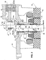
Figure 2 represents a view similar to that offigure 1 , but illustrating the radial bearings, of the crankshaft, constructed according to the invention, the crankshaft being inclined in relation to the axis of the bearing hub and of the larger eye of the connecting rod; -
Figure 3 represents an enlarged detail of the part offigure 2 which illustrates the radial bearings of the crankshaft; -
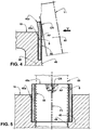
Figure 4 represents an enlarged and partial simplified vertical sectional view of the crankshaft portion, which presses and elastically and radially deforms, outwardly, the first end portion of the bearing hub, constructed according to a constructive variant for the bushing, according to the present invention; -
Figure 5 represents a simplified front view of the region of the first end portion of the bearing hub illustrated infigure 4 , said view being taken in the direction of arrow V of the previous figure, with the crankshaft illustrated in dashed lines; and -
Figure 6 represents a schematic perspective view of the elastically deformed bearing region, illustrated infigure 5 . - As already previously described and illustrated in
figures 1 and2 of the enclosed drawings, the bearing arrangements of the present invention are applied to a refrigeration compressor of the type which comprises, in the interior of a shell (not illustrated), acrankcase 10 defining, generally in a single cast piece, acylinder 20 having an axis Z, and abearing hub 40 which defines, internally, aradial bearing 41 having an axis X1. - A
crankshaft 50, having an axis Y1, is mounted in the interior of the radial bearing 41 of thebearing hub 40 and has aneccentric end portion 55, with an axis Y2 projecting outwards from afirst end portion 40a of thebearing hub 40, and afree end portion 56 which projects outwards from asecond end portion 40b of thebearing hub 40. - A
piston 30 is housed in thecylinder 20, so as to be displaced therein, in a reciprocating movement, by a connectingrod 60 which has an end defining alarger eye 61, mounted around theeccentric end portion 55 of thecrankshaft 50, and an opposite end carrying a coupling means 62 to allow coupling the connectingrod 60 to thepiston 30. The coupling means 62 can take the form of a smaller eye 62a, of a spherical joint (not illustrated), or any other means capable of carrying out the connecting rod-piston coupling. - In the illustrated construction, the smaller eye 62a is coupled to the
piston 30, by means of apiston pin 63, thecrankshaft 50 being rotatively driven by anelectric motor 70 which comprises arotor 71, mounted to thefree end portion 56 of thecrankshaft 50, and astator 72 attached to thecrankcase 10, around therotor 71. - As mentioned above, the
piston pin 63 and the smaller eye 62a of the connectingrod 60 can be replaced by a piston-connecting rod assembly having a spherical joint, or any other coupling arrangement, without departing from the constructive concept of the present invention. - The parts of
crankcase 10 andcrankshaft 50 may be constructed in any adequate well known prior art material as, for example, aluminum or cast iron alloys for thecrankcase 10, and steel or cast iron alloys for thecrankshaft 50. - Although
figure 3 does not illustrate the cylinder, the piston, part of the connecting rod and the electric motor, it should be understood that such parts were suppressed only for purposes of simplification of said figure, since they are already part of the type of compressor to which the present bearing arrangements are applied. - In an ideal condition for the assembly and operation of the compressor (not illustrated), the axis Y1 of the
crankshaft 50 coincides with the axis X1 of theradial bearing 41 of thebearing hub 40, and the axis X2 of thelarger eye 61 of the connectingrod 60 coincides with the axis Y2 of theeccentric end portion 55 of thecrankshaft 50. In this ideal condition, the axes Y1 and Y2 of thecrankshaft 50 and of itseccentric end portion 55 are orthogonal to the axis Z of thecylinder 20. - As already mentioned in the introduction of the present specification, position errors will always occur, in greater or lesser extent, in the construction of the components and in the assembly of the compressor, which cause some misalignment of the axes Y1 and Y2 of the
crankshaft 50 and of itseccentric end portion 55 in relation to the axes X1 and X2 of theradial bearing 41 and of thelarger eye 61 of the connectingrod 60, as well as loss of orthogonality between the axes Y1 and Y2 of thecrankshaft 50 and of itseccentric end portion 55 in relation to the axis Z of thecylinder 20. - In addition to the position errors mentioned above, it should be further considered the effects of the compression force F transmitted to the
eccentric end portion 55 of thecrankshaft 50 and which tends to cause deformation of the mechanism components and misalignment between the axes of the parts involved in these bearing regions, causing high levels of wear and energy consumption, as previously mentioned. - To the problems cited above, related to the position errors and to the compression forces, it can be added the problem of misalignment of the portions of
crankshaft 50 in relation to theradial bearing 41 and to thelarger eye 61, upon start of theelectric motor 70 with itsstator 72 presenting concentricity deviations in relation to theradial bearing 41, defined in the bearinghub 40. Said position and coaxiality errors, between thestator 72 and theradial bearing 41, and also the compression forces of the refrigerant gas, cause the positioning error of thecrankshaft 50 and of itseccentric end portion 55, respectively, in the interior of theradial bearing 41 and of thelarger eye 61 of the connectingrod 60, as illustrated infigures 1 ,2 and3 . - In the conventional constructions of the radial bearing parts, as illustrated in
figure 1 , the positioning error of thecrankshaft 50 and of itseccentric end portion 55, in the interior of theradial bearing 41 and of thelarger eye 61 of the connectingrod 60, respectively, causes thecrankshaft 50 to have circumferential portions of its surface with small dimensions, in the axial and circumferential directions, seated only on end circumferential regions, with small axial and circumferential dimensions, of the first andsecond end portions hub 40, and of theend portion 61a of thelarger eye 61 of the connectingrod 60, since these mutual contact regions or practically punctual bearing regions, under positioning error of the crankshaft, do not accommodate to the angular misalignment of the crankshaft in relation to the part of the radial bearing which supports said crankshaft. - Even in the cases in which it is provided, in the
first end portion 40a of the bearinghub 40, an elastically deformable radial region obtained by a circumferential groove or cutout provided in the bearinghub 40, it is only contemplated the interruption of the oil film in thefirst end portion 40a of the bearinghub 40, on which are applied, by thecrankshaft 50, the greatest forces derived from compression of the refrigerant gas by the piston. - However, the provision of a compliant region in the
first end portion 40a of the bearinghub 40 does not address the issue regarding the increase of torque of theelectric motor 70 and the wear by localized contact in thesecond end portion 40b of the bearinghub 40, at starts of theelectric motor 70, with therotor 71 presenting concentricity deviations in relation to thestator 72. - Besides the fact that the prior art provides only the possibility of compliance in a region of the
first end portion 40a of the bearinghub 40, it requires additional machining operations in thecrankcase 10, in order to form the region capable to present the compliance, as well as the end radial bearings extensions to be defined in the bearinghub 40. - The localized wear, produced by the operational condition of "inclination" of the
crankshaft 50, is high and it is also responsible for the loss of efficiency due to the rupture of the oil film in said bearing regions with a reduced area, often requiring the use of high viscosity oil or bearings with higher load capacity, which tends to increase the losses by viscous friction. - According to the present invention, the first and
second end portions hub 40 are each defined by arespective bushing extension hub 40 and presenting anend portion hub 40, so as to be elastically and radially deformed outwardly when pressed by a confronting portion of thecrankshaft 50, when the latter presents a coaxiality deviation of its axis Y1 in relation to the axis X1 of theradial bearing 41. - The dimensioning of the radial thickness and axial extension of said
end portions bushing extensions end portions crankshaft 50 with theradial bearing 41, in the positioning error condition of thecrankshaft 50 already mentioned above. In other words, each of theend portions bushing extensions crankshaft 50 and in the elastically deformed condition, a confronting region CR of surfaces having dimensions, in the axial and circumferential directions, which are capable of maintaining, in said regions, an oil film which separates, at least partially, the surfaces which form said the confronting region (CR) of surfaces. - The compliant regions, in the end portions of the bearing
hub 40, allow that the radial deformation of thebushing extensions - As illustrated in
figures 4, 5 and6 , the confronting region CR of surfaces of thedeformed end portion 45a, between thecrankshaft 50 and thebushing extension 45, in thefirst end portion 40a of the bearinghub 40, takes a nearly semi-elliptical form, with its end edge coinciding with the marginal edge of theadjacent end portion 45a of therespective bushing extension 45. It should be understood that the confronting region of surfaces, between thecrankshaft 50 and thebushing extension 46, in thesecond end portion 40b of the bearinghub 40, present, according to the present invention, the same configuration illustrated infigures 5 and6 . - Thus, it can be said that the invention produces a confronting region CR of surfaces, between the
crankshaft 50 and thebushing extensions radial bearing 41, in the first andsecond end portions hub 40, take a nearly semi-elliptical form, with its end edge coinciding with the marginal edge of theadjacent end portion respective bushing extension - Therefore, the solution proposed by the invention allows increasing the effective bearing area between said relatively moving parts of
crankshaft 50 and of radial bearing defined by thebushing extensions - The increase of the axial dimension of the confronting region CR of surfaces, between the parts of the
crankshaft 50 and the parts ofradial bearing 41, by means of elastic radial deformation of theend portions bushing extensions crankshaft 50 in its inevitable positioning error conditions, eliminating localized wear and loss of efficiency due to rupture of the oil films, transforming metal-metal friction into viscous friction, in said confronting region CR of surfaces of the tribological pairs. - The dimensions, in the axial and circumferential directions, of said elastically deformable end portions, are determined by the design characteristics of the compressor, the size and operational conditions of the compressor, and by the dimensional tolerances permitted in the manufacturing and assembly processes.
- Considering the
crankcase 10 as being usually produced in a cast metal alloy, its internal conformation for receiving and retaining thebushing extensions crankcase 10. As illustrated infigures 2 and3 , thecrankcase 10 has its end region, from which projects theeccentric end portion 55 of thecrankshaft 50, machined for forming arecess 11 around theradial bearing 41, within which is housed anaxial bearing 80, to support the weight of thecrankshaft 50 and of therotor 71 and which may present any adequate construction, such as a roller or a sliding bearing. However, while theend portion bushing extension bushing extension end portions hub 40, with the radial thickness reduced in relation to the largest diameter thereof, when the radial thickness required for thebushing extensions respective end portions crankshaft 50, which presents a coaxiality deviation of its axis in relation to the axis of the respective part ofradial bearing 41. It should be understood that said reduced thickness may be constant or variable, depending on the design characteristics of the compressor. - The fixation of the
bushing extensions hub 40, may be made in different ways. As illustrated infigures 2 and3 , the bearinghub 40 may be internally provided with an inner mediancircumferential projection 48, configured to define a stop for thebushing extensions second end portions hub 40 may be defined byrespective bushing extensions hub 40. In a constructive variant, also not illustrated, it is possible to provide two bushing extensions, in separate pieces, but which would be mutually and axially confronting in the inner median region of the bearing hub. - In these two cases, it is not provided the inner median
circumferential projection 48 illustrated in the construction offigures 2 e 3 . - The use of the
bushing extensions - In the construction illustrated in
figures 2 and3 , thebushing extensions - The
bushing extensions crankshaft 50 and the axis X1 of theradial bearing 41. - Regardless of the type of material used for the formation of the
bushing extensions end portions end portions crankshaft 50. - In addition to the constructive aspects mentioned above, it should be understood that the
bushing extensions - The bushing extensions may also be constructed in more than one material such as, for example, a material comprising an inner anti-friction layer AF, obtained in a polymeric material such as, for example, PTFE (polytetrafluorethylene), which is housed and retained within a jacket S, in a metallic material and to be equally affixed inside the bearing
hub 40, as schematically illustrated infigures 4 and 5 . - Further according to
figures 2 and3 , the end portion of thelarger eye 61 of the connectingrod 60, facing thecrankcase 10, may be defined by abushing extension 65 affixed in the interior of thelarger eye 61 and presenting anend portion 65a, which projects axially outwards from thelarger eye 61, so as to be elastically and radially deformed outwardly when pressed by a confronting portion of theeccentric end portion 55 of thecrankshaft 50 which presents a coaxiality deviation of its axis Y2 in relation to the axis X2 of thelarger eye 61. - As already described in relation to the
radial bearing 41, theend portion 65a of thebushing extension 65 defines, with the confronting portions of theeccentric end portion 55 of thecrankshaft 50, and in the elastically deformed condition, the confronting region CR of surfaces, having dimensions, in the axial and circumferential directions, capable of maintaining, in said regions, an oil film which separates, at least partially, the surfaces which form said confronting region CR of surfaces. - The
end portion 65a of thebushing extension 65 may present the same radial thickness of the remainder of thebushing extension 65, or a reduced radial thickness, as already described with respect to thebushing extensions radial bearing 41. - Further as previously described regarding the
bushing extensions radial bearing 41, the confronting region CR of surfaces, in the case of thebushing extension 65 of thelarger eye 61, takes a nearly semi-elliptical form, with its end edge coinciding with the adjacent marginal edge of theend portion 65a of therespective bushing extension 65 mounted in the interior of thelarger eye 61. - Also as previously described in relation to the
bushing extensions radial bearing 41, theend portion 65a of saidbushing extension 65 may present a radial thickness which is reduced in relation to that of the remainder of therespective bushing extension 65, which reduced thickness may have a constant or variable value. - It should also be understood that the
bushing extension 65 of thelarger eye 61 can be made in the same manner and with the same material variations, as already described above with respect to thebushing extensions hub 40. - It should also be noted that the constructive variants described herein may be presented either individually, in particular constructions, or also partially or totally combined with each other.
- While the invention has been described herein with reference to the construction illustrated in the enclosed drawings, it should be understood that the present arrangements may be applied to other possible compressor constructions, without departing from the inventive concept defined in the claims that accompany the present specification.
Claims (16)
- A refrigeration reciprocating compressor including bearing arrangements and comprising: a crankcase (10) carrying a cylinder (20) and a bearing hub (40) defining a radial bearing (41); a crankshaft (50) mounted in the radial bearing (41) and having an eccentric end portion (55) and a free end portion (56) which project outwards from a first and second end portions (40a, 40b), respectively, of the bearing hub (40); a piston (30) housed in the cylinder (20); and a connecting rod (60) coupling the eccentric end portion (55) of the crankshaft (50) to the piston (30), wherein the first end portion (40a) of the bearing hub (40) is defined by a bushing extension (45) affixed in the interior of the bearing hub (40) and presenting an end portion (45a), which projects axially, characterized in that the end portions (40a, 40b) of the bearing hub (40) are each defined by a respective bushing extension (45, 46) affixed in the interior of the bearing hub (40) and presenting an end portion (45a, 46a) which projects axially outwards from the bearing hub (40), so as to be elastically and radially deformed outwardly when pressed by a confronting portion of the crankshaft (50), which presents a coaxiality deviation of its axis (Y1) in relation to the axis (X1) of the radial bearing (41).
- The refrigeration reciprocating compressor as set forth in claim 1, characterized in that each of the end portions (45a, 46a) of the bushing extensions (45, 46) defines, with a confronting part of the crankshaft (50), in the elastically deformed condition, a confronting region (CR) of surfaces having dimensions, in the axial and circumferential directions, capable of maintaining, in said regions, an oil film which separates, at least partially, the surfaces which form said confronting region (CR) of surfaces.
- The refrigeration reciprocating compressor as set forth in claim 2, characterized in that the end portion (45a, 46a) of the bushing extension (45, 46) presents the same radial thickness of the remainder of the bushing extension (45, 46).
- The refrigeration reciprocating compressor as set forth in any of claims 2 or 3, characterized in that the confronting region (CR) of surfaces takes a nearly semi-elliptical form, with its end edge coinciding with the marginal edge of the adjacent end portion (45a, 46a) of the respective bushing extension (45, 46).
- The refrigeration reciprocating compressor as set forth in any of claims 1 to 4, characterized in that the bushing extensions (45, 46) define end parts of a single piece.
- The refrigeration reciprocating compressor as set forth in any of claims 1 to 5, in which the connecting rod (60) has a larger eye (61) mounted around the eccentric end portion (55) of the crankshaft (50) and being coupled, by an opposite end, to the piston (30), characterized in that the end portion of the larger eye (61) of the connecting rod (60), facing the crankcase (10), is defined by a bushing extension (65) affixed in the interior of the larger eye (61) and presenting an end portion (65a), which projects axially outwards from the larger eye (61), so as to be elastically and radially deformed outwardly when pressed by a confronting portion of the eccentric end portion (55) of the crankshaft (50) which presents a coaxiality deviation of its axis (Y2) in relation to the axis (X2) of the larger eye (61).
- The refrigeration reciprocating compressor as set forth in claim 6, characterized in that the end portion (65a) of the bushing extension (65) defines, with the confronting portion of the eccentric end portion (55) of the crankshaft (50) and in the elastically deformed condition, a confronting region (CR) of surfaces, having dimensions, in the axial and circumferential directions, capable of maintaining, in said regions, an oil film which separates, at least partially, the surfaces which form said confronting region (CR) of surfaces.
- The refrigeration reciprocating compressor as set forth in claim 7, characterized in that the end portion (65a) of the bushing extension (65) presents the same radial thickness of the remainder of the bushing extension (65).
- The refrigeration reciprocating compressor as set forth in any of claims 6 to 8, characterized in that the confronting region (CR) of surfaces takes a nearly semi-elliptical form, with its end edge coinciding with the adjacent marginal edge of one of the parts of radial bearing (40a, 40b, 45a, 46a) and of the larger eye (61).
- The refrigeration reciprocating compressor as set forth in any of claims 1, 2, 4 to 7 and 9, characterized in that the end portion (45a, 46a, 65a) of each bushing extension (45, 46, 65) presents a radial thickness reduced in relation to that of the remainder of the respective bushing extension (45, 46, 65).
- The refrigeration reciprocating compressor as set forth in claim 10, characterized in that the reduced radial thickness of the end portion (45a, 46a, 65a) of at least one of the bushing extensions (45, 46, 65) is constant.
- The refrigeration reciprocating compressor as set forth in any of claims 1 to 11, characterized in that at least one of the bushing extensions (45, 46, 65) is made in a metal alloy selected from iron, aluminum and nickel.
- The refrigeration reciprocating compressor as set forth in claim 12, characterized in that at least one of the bushing extensions (45, 46, 65) is made in a self-lubricating material defined by a metallic alloy matrix incorporating a dispersion of non-metallic solid lubricant.
- The refrigeration reciprocating compressor as set forth in claim 12, characterized in that at least one of the bushing extensions (45, 46, 65) is provided with a surface treatment for reducing wear and/or the friction coefficient.
- The refrigeration reciprocating compressor as set forth in any of claims 1 to 11, characterized in that at least one of the bushing extensions (45, 46, 65) is formed in a single material defined by an engineering polymer.
- The refrigeration reciprocating compressor as set forth in any of claims 1 to 11, characterized in that at least one of the bushing extensions (45, 46, 65) comprises an inner anti-friction layer (AF), obtained in a polymeric material and which is housed and retained in the interior of a jacket (S) in a metallic material and to be affixed inside the bearing hub (40).
Applications Claiming Priority (2)
| Application Number | Priority Date | Filing Date | Title |
|---|---|---|---|
| BR102012025039-0A BR102012025039B1 (en) | 2012-10-01 | 2012-10-01 | RADIAL BEARING IMPROVEMENTS IN AN ALTERNATIVE COOLING COMPRESSOR |
| PCT/BR2013/000383 WO2014053036A1 (en) | 2012-10-01 | 2013-08-01 | Bearing arrangements in a refrigeration reciprocating compressor |
Publications (2)
| Publication Number | Publication Date |
|---|---|
| EP2904279A1 EP2904279A1 (en) | 2015-08-12 |
| EP2904279B1 true EP2904279B1 (en) | 2020-03-18 |
Family
ID=49484050
Family Applications (1)
| Application Number | Title | Priority Date | Filing Date |
|---|---|---|---|
| EP13780305.2A Active EP2904279B1 (en) | 2012-10-01 | 2013-08-01 | A refrigeration reciprocating compressor including bearing arrangements |
Country Status (9)
| Country | Link |
|---|---|
| US (1) | US9611888B2 (en) |
| EP (1) | EP2904279B1 (en) |
| JP (1) | JP2015535903A (en) |
| KR (1) | KR20150063063A (en) |
| CN (1) | CN104813040B (en) |
| BR (1) | BR102012025039B1 (en) |
| ES (1) | ES2803526T3 (en) |
| SG (1) | SG11201502218WA (en) |
| WO (1) | WO2014053036A1 (en) |
Families Citing this family (8)
| Publication number | Priority date | Publication date | Assignee | Title |
|---|---|---|---|---|
| CN105570278B (en) * | 2016-01-28 | 2020-08-14 | 珠海格力电器股份有限公司 | Connecting rod and reciprocating compressor |
| JP7795294B2 (en) * | 2018-06-27 | 2026-01-07 | パナソニック株式会社 | Hermetic refrigerant compressor and refrigeration/freezing device using same |
| CN110761977A (en) * | 2019-10-29 | 2020-02-07 | 东贝机电(江苏)有限公司 | Oil suspension type cylinder seat bearing structure |
| JP7722926B2 (en) * | 2019-11-25 | 2025-08-13 | パナソニック株式会社 | Hermetic refrigerant compressor and refrigeration/freezing device using same |
| JP2022043621A (en) * | 2020-09-04 | 2022-03-16 | 日立グローバルライフソリューションズ株式会社 | Hermetic compressor |
| CN114856967B (en) * | 2022-06-02 | 2023-03-28 | 珠海格力电器股份有限公司 | Crankshaft and compressor |
| IT202200024036A1 (en) * | 2022-11-22 | 2024-05-22 | Officine Mario Dorin S P A | MODULAR RECIPROCATING COMPRESSOR WITH RADIAL CYLINDERS |
| CN116642127B (en) * | 2023-07-21 | 2024-05-07 | 河南豫氢装备有限公司 | High-pressure hydrogen filling gun for hydrogen fuel cell automobile and use method thereof |
Citations (1)
| Publication number | Priority date | Publication date | Assignee | Title |
|---|---|---|---|---|
| US6190137B1 (en) * | 1999-09-24 | 2001-02-20 | Tecumseh Products Company | Reversible, variable displacement compressor |
Family Cites Families (11)
| Publication number | Priority date | Publication date | Assignee | Title |
|---|---|---|---|---|
| US1347443A (en) * | 1919-04-03 | 1920-07-20 | Christiani Thomas | Automatically-adjustable bearing |
| US2703737A (en) * | 1952-05-15 | 1955-03-08 | Maytag Co | Self-adjusting thrust bearings |
| US4828403A (en) * | 1987-04-03 | 1989-05-09 | Schwartzman Everett H | Resiliently mounted fluid bearing assembly |
| CH675283A5 (en) | 1988-03-25 | 1990-09-14 | Asea Brown Boveri | |
| BR9600687A (en) | 1996-03-13 | 1998-01-21 | Brasil Compressores Sa | Axial bearing for hermetic compressor |
| DE10053574B4 (en) * | 2000-10-28 | 2005-07-28 | Danfoss Compressors Gmbh | Piston compressor, in particular hermetically sealed refrigerant compressor |
| EP2191134B1 (en) | 2007-08-31 | 2011-01-19 | Arçelik Anonim Sirketi | A compressor |
| KR101463833B1 (en) | 2009-01-07 | 2014-11-20 | 엘지전자 주식회사 | Reciprocating compressor and refrigerating machine having the same |
| BRPI0902973B1 (en) | 2009-08-27 | 2020-03-10 | Embraco Indústria De Compressores E Soluções E Refrigeração Ltda. | ALTERNATIVE REFRIGERATION COMPRESSOR BLOCK |
| KR20110101496A (en) * | 2010-03-08 | 2011-09-16 | 엘지전자 주식회사 | Reciprocating compressors and freezers using them |
| BRPI1100652B1 (en) * | 2011-01-13 | 2021-08-10 | Embraco Indústria De Compressores E Soluções Em Refrigeração Ltda | BEARING ARRANGEMENT FOR AN ALTERNATIVE COOLING COMPRESSOR |
-
2012
- 2012-10-01 BR BR102012025039-0A patent/BR102012025039B1/en active IP Right Grant
-
2013
- 2013-08-01 KR KR1020157008443A patent/KR20150063063A/en not_active Withdrawn
- 2013-08-01 ES ES13780305T patent/ES2803526T3/en active Active
- 2013-08-01 CN CN201380058196.3A patent/CN104813040B/en active Active
- 2013-08-01 EP EP13780305.2A patent/EP2904279B1/en active Active
- 2013-08-01 SG SG11201502218WA patent/SG11201502218WA/en unknown
- 2013-08-01 US US14/432,306 patent/US9611888B2/en not_active Expired - Fee Related
- 2013-08-01 WO PCT/BR2013/000383 patent/WO2014053036A1/en not_active Ceased
- 2013-08-01 JP JP2015533383A patent/JP2015535903A/en active Pending
Patent Citations (1)
| Publication number | Priority date | Publication date | Assignee | Title |
|---|---|---|---|---|
| US6190137B1 (en) * | 1999-09-24 | 2001-02-20 | Tecumseh Products Company | Reversible, variable displacement compressor |
Also Published As
| Publication number | Publication date |
|---|---|
| BR102012025039B1 (en) | 2021-09-28 |
| CN104813040B (en) | 2017-07-11 |
| SG11201502218WA (en) | 2015-04-29 |
| US20150267743A1 (en) | 2015-09-24 |
| JP2015535903A (en) | 2015-12-17 |
| CN104813040A (en) | 2015-07-29 |
| KR20150063063A (en) | 2015-06-08 |
| WO2014053036A1 (en) | 2014-04-10 |
| EP2904279A1 (en) | 2015-08-12 |
| BR102012025039A2 (en) | 2015-10-27 |
| US9611888B2 (en) | 2017-04-04 |
| ES2803526T3 (en) | 2021-01-27 |
Similar Documents
| Publication | Publication Date | Title |
|---|---|---|
| US9611888B2 (en) | Bearing arrangements in a refrigeration reciprocating compressor | |
| EP2455627B1 (en) | Anti-abrasion apparatus and reciprocating compressor adopting the same | |
| US10309383B2 (en) | Bearing arrangement for a reciprocating compressor | |
| WO2012071639A1 (en) | Tribological pair and process for surface treatment in tribological pairs | |
| EP2947321A1 (en) | Multi-cylinder rotary compressor | |
| EP2470789B1 (en) | Block for a reciprocating refrigeration compressor | |
| EP3126675B1 (en) | Radial bearing arrangement in a refrigeration compressor | |
| JP5287400B2 (en) | Radial plain bearing | |
| JP5429026B2 (en) | Radial slide bearing and rotating shaft bearing structure | |
| JP2010223181A (en) | Fuel injection pump | |
| US6841900B2 (en) | Reciprocating device and linear suspension | |
| CN218325221U (en) | Diaphragm compressor crankshaft positioning device | |
| EP3176393B1 (en) | Cam follower roller device with spacer and improved wear resistance | |
| WO2017186798A1 (en) | Shell bearing for internal combustion engines |
Legal Events
| Date | Code | Title | Description |
|---|---|---|---|
| PUAI | Public reference made under article 153(3) epc to a published international application that has entered the european phase |
Free format text: ORIGINAL CODE: 0009012 |
|
| 17P | Request for examination filed |
Effective date: 20150504 |
|
| AK | Designated contracting states |
Kind code of ref document: A1 Designated state(s): AL AT BE BG CH CY CZ DE DK EE ES FI FR GB GR HR HU IE IS IT LI LT LU LV MC MK MT NL NO PL PT RO RS SE SI SK SM TR |
|
| AX | Request for extension of the european patent |
Extension state: BA ME |
|
| DAX | Request for extension of the european patent (deleted) | ||
| STAA | Information on the status of an ep patent application or granted ep patent |
Free format text: STATUS: EXAMINATION IS IN PROGRESS |
|
| 17Q | First examination report despatched |
Effective date: 20180206 |
|
| REG | Reference to a national code |
Ref country code: DE Ref legal event code: R079 Ref document number: 602013066964 Country of ref document: DE Free format text: PREVIOUS MAIN CLASS: F16C0003140000 Ipc: F16C0009020000 |
|
| RIC1 | Information provided on ipc code assigned before grant |
Ipc: F16C 9/02 20060101AFI20190704BHEP |
|
| GRAP | Despatch of communication of intention to grant a patent |
Free format text: ORIGINAL CODE: EPIDOSNIGR1 |
|
| STAA | Information on the status of an ep patent application or granted ep patent |
Free format text: STATUS: GRANT OF PATENT IS INTENDED |
|
| INTG | Intention to grant announced |
Effective date: 20191002 |
|
| GRAS | Grant fee paid |
Free format text: ORIGINAL CODE: EPIDOSNIGR3 |
|
| GRAA | (expected) grant |
Free format text: ORIGINAL CODE: 0009210 |
|
| STAA | Information on the status of an ep patent application or granted ep patent |
Free format text: STATUS: THE PATENT HAS BEEN GRANTED |
|
| AK | Designated contracting states |
Kind code of ref document: B1 Designated state(s): AL AT BE BG CH CY CZ DE DK EE ES FI FR GB GR HR HU IE IS IT LI LT LU LV MC MK MT NL NO PL PT RO RS SE SI SK SM TR |
|
| REG | Reference to a national code |
Ref country code: GB Ref legal event code: FG4D |
|
| REG | Reference to a national code |
Ref country code: DE Ref legal event code: R096 Ref document number: 602013066964 Country of ref document: DE |
|
| REG | Reference to a national code |
Ref country code: AT Ref legal event code: REF Ref document number: 1246216 Country of ref document: AT Kind code of ref document: T Effective date: 20200415 Ref country code: IE Ref legal event code: FG4D |
|
| PG25 | Lapsed in a contracting state [announced via postgrant information from national office to epo] |
Ref country code: FI Free format text: LAPSE BECAUSE OF FAILURE TO SUBMIT A TRANSLATION OF THE DESCRIPTION OR TO PAY THE FEE WITHIN THE PRESCRIBED TIME-LIMIT Effective date: 20200318 Ref country code: NO Free format text: LAPSE BECAUSE OF FAILURE TO SUBMIT A TRANSLATION OF THE DESCRIPTION OR TO PAY THE FEE WITHIN THE PRESCRIBED TIME-LIMIT Effective date: 20200618 Ref country code: RS Free format text: LAPSE BECAUSE OF FAILURE TO SUBMIT A TRANSLATION OF THE DESCRIPTION OR TO PAY THE FEE WITHIN THE PRESCRIBED TIME-LIMIT Effective date: 20200318 |
|
| REG | Reference to a national code |
Ref country code: NL Ref legal event code: MP Effective date: 20200318 |
|
| PG25 | Lapsed in a contracting state [announced via postgrant information from national office to epo] |
Ref country code: HR Free format text: LAPSE BECAUSE OF FAILURE TO SUBMIT A TRANSLATION OF THE DESCRIPTION OR TO PAY THE FEE WITHIN THE PRESCRIBED TIME-LIMIT Effective date: 20200318 Ref country code: SE Free format text: LAPSE BECAUSE OF FAILURE TO SUBMIT A TRANSLATION OF THE DESCRIPTION OR TO PAY THE FEE WITHIN THE PRESCRIBED TIME-LIMIT Effective date: 20200318 Ref country code: LV Free format text: LAPSE BECAUSE OF FAILURE TO SUBMIT A TRANSLATION OF THE DESCRIPTION OR TO PAY THE FEE WITHIN THE PRESCRIBED TIME-LIMIT Effective date: 20200318 Ref country code: BG Free format text: LAPSE BECAUSE OF FAILURE TO SUBMIT A TRANSLATION OF THE DESCRIPTION OR TO PAY THE FEE WITHIN THE PRESCRIBED TIME-LIMIT Effective date: 20200618 |
|
| REG | Reference to a national code |
Ref country code: LT Ref legal event code: MG4D |
|
| PG25 | Lapsed in a contracting state [announced via postgrant information from national office to epo] |
Ref country code: NL Free format text: LAPSE BECAUSE OF FAILURE TO SUBMIT A TRANSLATION OF THE DESCRIPTION OR TO PAY THE FEE WITHIN THE PRESCRIBED TIME-LIMIT Effective date: 20200318 |
|
| REG | Reference to a national code |
Ref country code: SK Ref legal event code: T3 Ref document number: E 34707 Country of ref document: SK |
|
| PG25 | Lapsed in a contracting state [announced via postgrant information from national office to epo] |
Ref country code: IS Free format text: LAPSE BECAUSE OF FAILURE TO SUBMIT A TRANSLATION OF THE DESCRIPTION OR TO PAY THE FEE WITHIN THE PRESCRIBED TIME-LIMIT Effective date: 20200718 Ref country code: RO Free format text: LAPSE BECAUSE OF FAILURE TO SUBMIT A TRANSLATION OF THE DESCRIPTION OR TO PAY THE FEE WITHIN THE PRESCRIBED TIME-LIMIT Effective date: 20200318 Ref country code: LT Free format text: LAPSE BECAUSE OF FAILURE TO SUBMIT A TRANSLATION OF THE DESCRIPTION OR TO PAY THE FEE WITHIN THE PRESCRIBED TIME-LIMIT Effective date: 20200318 Ref country code: CZ Free format text: LAPSE BECAUSE OF FAILURE TO SUBMIT A TRANSLATION OF THE DESCRIPTION OR TO PAY THE FEE WITHIN THE PRESCRIBED TIME-LIMIT Effective date: 20200318 Ref country code: PT Free format text: LAPSE BECAUSE OF FAILURE TO SUBMIT A TRANSLATION OF THE DESCRIPTION OR TO PAY THE FEE WITHIN THE PRESCRIBED TIME-LIMIT Effective date: 20200812 Ref country code: EE Free format text: LAPSE BECAUSE OF FAILURE TO SUBMIT A TRANSLATION OF THE DESCRIPTION OR TO PAY THE FEE WITHIN THE PRESCRIBED TIME-LIMIT Effective date: 20200318 Ref country code: SM Free format text: LAPSE BECAUSE OF FAILURE TO SUBMIT A TRANSLATION OF THE DESCRIPTION OR TO PAY THE FEE WITHIN THE PRESCRIBED TIME-LIMIT Effective date: 20200318 |
|
| REG | Reference to a national code |
Ref country code: DE Ref legal event code: R097 Ref document number: 602013066964 Country of ref document: DE |
|
| PLBE | No opposition filed within time limit |
Free format text: ORIGINAL CODE: 0009261 |
|
| STAA | Information on the status of an ep patent application or granted ep patent |
Free format text: STATUS: NO OPPOSITION FILED WITHIN TIME LIMIT |
|
| REG | Reference to a national code |
Ref country code: ES Ref legal event code: FG2A Ref document number: 2803526 Country of ref document: ES Kind code of ref document: T3 Effective date: 20210127 |
|
| PG25 | Lapsed in a contracting state [announced via postgrant information from national office to epo] |
Ref country code: DK Free format text: LAPSE BECAUSE OF FAILURE TO SUBMIT A TRANSLATION OF THE DESCRIPTION OR TO PAY THE FEE WITHIN THE PRESCRIBED TIME-LIMIT Effective date: 20200318 |
|
| 26N | No opposition filed |
Effective date: 20201221 |
|
| PG25 | Lapsed in a contracting state [announced via postgrant information from national office to epo] |
Ref country code: PL Free format text: LAPSE BECAUSE OF FAILURE TO SUBMIT A TRANSLATION OF THE DESCRIPTION OR TO PAY THE FEE WITHIN THE PRESCRIBED TIME-LIMIT Effective date: 20200318 |
|
| PG25 | Lapsed in a contracting state [announced via postgrant information from national office to epo] |
Ref country code: MC Free format text: LAPSE BECAUSE OF FAILURE TO SUBMIT A TRANSLATION OF THE DESCRIPTION OR TO PAY THE FEE WITHIN THE PRESCRIBED TIME-LIMIT Effective date: 20200318 |
|
| REG | Reference to a national code |
Ref country code: CH Ref legal event code: PL |
|
| GBPC | Gb: european patent ceased through non-payment of renewal fee |
Effective date: 20200801 |
|
| REG | Reference to a national code |
Ref country code: SK Ref legal event code: MM4A Ref document number: E 34707 Country of ref document: SK Effective date: 20200801 |
|
| PG25 | Lapsed in a contracting state [announced via postgrant information from national office to epo] |
Ref country code: LI Free format text: LAPSE BECAUSE OF NON-PAYMENT OF DUE FEES Effective date: 20200831 Ref country code: CH Free format text: LAPSE BECAUSE OF NON-PAYMENT OF DUE FEES Effective date: 20200831 Ref country code: LU Free format text: LAPSE BECAUSE OF NON-PAYMENT OF DUE FEES Effective date: 20200801 |
|
| REG | Reference to a national code |
Ref country code: BE Ref legal event code: MM Effective date: 20200831 |
|
| PG25 | Lapsed in a contracting state [announced via postgrant information from national office to epo] |
Ref country code: SI Free format text: LAPSE BECAUSE OF FAILURE TO SUBMIT A TRANSLATION OF THE DESCRIPTION OR TO PAY THE FEE WITHIN THE PRESCRIBED TIME-LIMIT Effective date: 20200318 |
|
| PG25 | Lapsed in a contracting state [announced via postgrant information from national office to epo] |
Ref country code: SK Free format text: LAPSE BECAUSE OF NON-PAYMENT OF DUE FEES Effective date: 20200801 |
|
| PG25 | Lapsed in a contracting state [announced via postgrant information from national office to epo] |
Ref country code: FR Free format text: LAPSE BECAUSE OF NON-PAYMENT OF DUE FEES Effective date: 20200831 |
|
| PG25 | Lapsed in a contracting state [announced via postgrant information from national office to epo] |
Ref country code: IE Free format text: LAPSE BECAUSE OF NON-PAYMENT OF DUE FEES Effective date: 20200801 Ref country code: GB Free format text: LAPSE BECAUSE OF NON-PAYMENT OF DUE FEES Effective date: 20200801 Ref country code: BE Free format text: LAPSE BECAUSE OF NON-PAYMENT OF DUE FEES Effective date: 20200831 |
|
| PG25 | Lapsed in a contracting state [announced via postgrant information from national office to epo] |
Ref country code: IT Free format text: LAPSE BECAUSE OF NON-PAYMENT OF DUE FEES Effective date: 20200801 |
|
| PGFP | Annual fee paid to national office [announced via postgrant information from national office to epo] |
Ref country code: AT Payment date: 20210820 Year of fee payment: 9 |
|
| PGFP | Annual fee paid to national office [announced via postgrant information from national office to epo] |
Ref country code: DE Payment date: 20210920 Year of fee payment: 9 |
|
| PGFP | Annual fee paid to national office [announced via postgrant information from national office to epo] |
Ref country code: TR Payment date: 20211018 Year of fee payment: 9 Ref country code: ES Payment date: 20211026 Year of fee payment: 9 |
|
| PG25 | Lapsed in a contracting state [announced via postgrant information from national office to epo] |
Ref country code: MT Free format text: LAPSE BECAUSE OF FAILURE TO SUBMIT A TRANSLATION OF THE DESCRIPTION OR TO PAY THE FEE WITHIN THE PRESCRIBED TIME-LIMIT Effective date: 20200318 Ref country code: CY Free format text: LAPSE BECAUSE OF FAILURE TO SUBMIT A TRANSLATION OF THE DESCRIPTION OR TO PAY THE FEE WITHIN THE PRESCRIBED TIME-LIMIT Effective date: 20200318 |
|
| PG25 | Lapsed in a contracting state [announced via postgrant information from national office to epo] |
Ref country code: MK Free format text: LAPSE BECAUSE OF FAILURE TO SUBMIT A TRANSLATION OF THE DESCRIPTION OR TO PAY THE FEE WITHIN THE PRESCRIBED TIME-LIMIT Effective date: 20200318 Ref country code: AL Free format text: LAPSE BECAUSE OF FAILURE TO SUBMIT A TRANSLATION OF THE DESCRIPTION OR TO PAY THE FEE WITHIN THE PRESCRIBED TIME-LIMIT Effective date: 20200318 |
|
| PG25 | Lapsed in a contracting state [announced via postgrant information from national office to epo] |
Ref country code: GR Free format text: LAPSE BECAUSE OF FAILURE TO SUBMIT A TRANSLATION OF THE DESCRIPTION OR TO PAY THE FEE WITHIN THE PRESCRIBED TIME-LIMIT Effective date: 20200318 |
|
| REG | Reference to a national code |
Ref country code: DE Ref legal event code: R119 Ref document number: 602013066964 Country of ref document: DE |
|
| REG | Reference to a national code |
Ref country code: AT Ref legal event code: MM01 Ref document number: 1246216 Country of ref document: AT Kind code of ref document: T Effective date: 20220801 |
|
| PG25 | Lapsed in a contracting state [announced via postgrant information from national office to epo] |
Ref country code: AT Free format text: LAPSE BECAUSE OF NON-PAYMENT OF DUE FEES Effective date: 20220801 |
|
| PG25 | Lapsed in a contracting state [announced via postgrant information from national office to epo] |
Ref country code: DE Free format text: LAPSE BECAUSE OF NON-PAYMENT OF DUE FEES Effective date: 20230301 |
|
| REG | Reference to a national code |
Ref country code: ES Ref legal event code: FD2A Effective date: 20230926 |
|
| PG25 | Lapsed in a contracting state [announced via postgrant information from national office to epo] |
Ref country code: ES Free format text: LAPSE BECAUSE OF NON-PAYMENT OF DUE FEES Effective date: 20220802 |
|
| PG25 | Lapsed in a contracting state [announced via postgrant information from national office to epo] |
Ref country code: TR Free format text: LAPSE BECAUSE OF NON-PAYMENT OF DUE FEES Effective date: 20220801 |
|
| REG | Reference to a national code |
Ref country code: AT Ref legal event code: UEP Ref document number: 1246216 Country of ref document: AT Kind code of ref document: T Effective date: 20200318 |