EP2903862B1 - Visual locating device for a motor vehicle - Google Patents
Visual locating device for a motor vehicle Download PDFInfo
- Publication number
- EP2903862B1 EP2903862B1 EP13803240.4A EP13803240A EP2903862B1 EP 2903862 B1 EP2903862 B1 EP 2903862B1 EP 13803240 A EP13803240 A EP 13803240A EP 2903862 B1 EP2903862 B1 EP 2903862B1
- Authority
- EP
- European Patent Office
- Prior art keywords
- motor vehicle
- light signal
- optoelectronic
- light
- antenna
- Prior art date
- Legal status (The legal status is an assumption and is not a legal conclusion. Google has not performed a legal analysis and makes no representation as to the accuracy of the status listed.)
- Active
Links
Images

Classifications
-
- G—PHYSICS
- G08—SIGNALLING
- G08G—TRAFFIC CONTROL SYSTEMS
- G08G1/00—Traffic control systems for road vehicles
- G08G1/123—Traffic control systems for road vehicles indicating the position of vehicles, e.g. scheduled vehicles; Managing passenger vehicles circulating according to a fixed timetable, e.g. buses, trains, trams
-
- B—PERFORMING OPERATIONS; TRANSPORTING
- B60—VEHICLES IN GENERAL
- B60Q—ARRANGEMENT OF SIGNALLING OR LIGHTING DEVICES, THE MOUNTING OR SUPPORTING THEREOF OR CIRCUITS THEREFOR, FOR VEHICLES IN GENERAL
- B60Q1/00—Arrangement of optical signalling or lighting devices, the mounting or supporting thereof or circuits therefor
- B60Q1/26—Arrangement of optical signalling or lighting devices, the mounting or supporting thereof or circuits therefor the devices being primarily intended to indicate the vehicle, or parts thereof, or to give signals, to other traffic
- B60Q1/48—Arrangement of optical signalling or lighting devices, the mounting or supporting thereof or circuits therefor the devices being primarily intended to indicate the vehicle, or parts thereof, or to give signals, to other traffic for parking purposes
- B60Q1/482—Arrangement of optical signalling or lighting devices, the mounting or supporting thereof or circuits therefor the devices being primarily intended to indicate the vehicle, or parts thereof, or to give signals, to other traffic for parking purposes for locating vehicle in parking lot
-
- G—PHYSICS
- G08—SIGNALLING
- G08B—SIGNALLING SYSTEMS, e.g. PERSONAL CALLING SYSTEMS; ORDER TELEGRAPHS; ALARM SYSTEMS
- G08B5/00—Visible signalling systems, e.g. visible personal calling systems or remote indication of seats occupied
- G08B5/22—Visible signalling systems, e.g. visible personal calling systems or remote indication of seats occupied using electric transmission; using electromagnetic transmission
- G08B5/36—Visible signalling systems, e.g. visible personal calling systems or remote indication of seats occupied using electric transmission; using electromagnetic transmission using visible light sources
-
- H—ELECTRICITY
- H01—ELECTRIC ELEMENTS
- H01Q—ANTENNAS, i.e. RADIO AERIALS
- H01Q1/00—Details of, or arrangements associated with, antennas
- H01Q1/06—Means for the lighting or illuminating of antennas, e.g. for purpose of warning
-
- H—ELECTRICITY
- H01—ELECTRIC ELEMENTS
- H01Q—ANTENNAS, i.e. RADIO AERIALS
- H01Q1/00—Details of, or arrangements associated with, antennas
- H01Q1/27—Adaptation for use in or on movable bodies
- H01Q1/32—Adaptation for use in or on road or rail vehicles
- H01Q1/325—Adaptation for use in or on road or rail vehicles characterised by the location of the antenna on the vehicle
- H01Q1/3275—Adaptation for use in or on road or rail vehicles characterised by the location of the antenna on the vehicle mounted on a horizontal surface of the vehicle, e.g. on roof, hood, trunk
-
- H—ELECTRICITY
- H01—ELECTRIC ELEMENTS
- H01Q—ANTENNAS, i.e. RADIO AERIALS
- H01Q1/00—Details of, or arrangements associated with, antennas
- H01Q1/27—Adaptation for use in or on movable bodies
- H01Q1/32—Adaptation for use in or on road or rail vehicles
- H01Q1/3208—Adaptation for use in or on road or rail vehicles characterised by the application wherein the antenna is used
- H01Q1/3233—Adaptation for use in or on road or rail vehicles characterised by the application wherein the antenna is used particular used as part of a sensor or in a security system, e.g. for automotive radar, navigation systems
- H01Q1/3241—Adaptation for use in or on road or rail vehicles characterised by the application wherein the antenna is used particular used as part of a sensor or in a security system, e.g. for automotive radar, navigation systems particular used in keyless entry systems
Definitions
- the present invention relates to a visual locating device for a motor vehicle, in particular a passenger car.
- US Patent 6,239,701 describes a visual locating device for a motor vehicle, which can be combined with anantenna of the motor vehicle's radio system to emit, when activated, a flashing light signal in order to facilitate visually locating the motor vehicle within a search area, for example, in a car park.
- US Patent 7,119,679 describes a visual locating device for a motor vehicle in which a spherical body made of a transparent material and housing a light source can be coupled with the tip of the antenna of a motor vehicle's radio system; the light source can be activated by means of a wireless command generated by a remote control to produce a light signal suitable to enable locating the motor vehicle.
- a device for generating a sound signal is available within the body of the motor vehicle, for example inside the engine compartment, and can also be activated remotely by means of a remote control, which can enable the generation of just the sound signal or a sound and light signal.
- European Patent EP 1 630 051 describes a solution similar to that described in US Patent 7,119,679 , in which the signalling unit that can be coupled with the antenna of a motor vehicle's radio system can be activated remotely by means of a remote control and is able to generate a light and sound signal.
- US 7,369,061 B1 discloses a visual locating device for a motor vehicle, comprising: an optoelectronic light signal generator operable to emit a light signal; and an electronic control circuit responsive to activation/setting commands to accordingly control the optoelectronic light signal generator to cause emission of a light signal suitable to enable visually locating the motor vehicle; wherein the optoelectronic light signal generator comprises: an optoelectronic light source operable to generate a light signal, and a transparent lens cover configured to be mechanically coupleable with an external antenna of the motor vehicle, wherein the transparent lens cover is configured to be fastenable to a body part of the motor vehicle via a base plate where an associated electronic control circuit is housed; wherein the electronic control circuit is further configured to cause distinct light patterns and the light flash intensity of the light signal generated by the optoelectronic light signal generator to be user-settable remotely from the motor vehicle; and wherein the electronic control system is further configured to allow the optoelectronic light signal generator to be remotely activated via
- Known types of visual location devices generate a light signal having fixed characteristics, for example intensity and/or duration.
- this signal is not suitable to allow easy identification of the motor vehicle: consider, for example, a light signal that can be suitable in certain lighting conditions, but insufficient in situations of high brightness.
- the light source described in US Patent 7,119,679 is a normal incandescent light bulb mounted in a socket housed inside the spherical body.
- This structure comprises metal parts that can magnetically interfere with the original structure of the antenna, deteriorating its performance.
- connection between the transparent plastic body and the tip of the antenna is not stable and the plastic body can come loose from the antenna, for example, due to vibrations transmitted by the motor vehicle and/or the waving movement of the antenna due to the motor vehicle moving forward. This constitutes a further technical problem of the known art.
- the object of the present invention is that of providing a visual locating device for a motor vehicle, in particular a passenger car, which overcomes the drawbacks of the known art.
- reference numeral 1 indicates, as a whole, a visual locating device for a motor vehicle 2, in particular a passenger car (schematically and partially shown in Figures 2 and 3 ).
- the locating device 1 comprises:
- the antenna 5 extends upwards from the roof of the motor vehicle's body and comprises a straight elongated insulating element 11 containing the circuit portion of the antenna (of known type and not shown for simplicity).
- the light signal generator 4 comprises a plurality of LEDs (light emitting diodes) 4-L powered by a driving circuit (of known type and not shown for simplicity), and a waveguide 15 coupled to the antenna 5 to receive the optical signal generated by the LEDS 4-L.
- the waveguide 15 is made of a transparent material so that the optical signal generated by the LEDS 4-L is fed to the inlet of the waveguide 15 and enables the illumination of at least part of the waveguide 15, providing the aforementioned visual indication.
- the optical signal can provide illumination for the entire length of the waveguide or illuminate one or more portions of the waveguide, for example, an end portion.
- the waveguide 15 is made of a synthetic material and does not interfere with the electromagnetic structure of the antenna 5. Furthermore, even the LEDs 4-L do not effectively comprise materials that could cause electromagnetic interference with the antenna 5.
- the visual locating device 1 is extremely simple, robust, inexpensive and not subject to deterioration.
- the waveguide 15 comprises a single straight element 17, made of a synthetic material, which extends along the antenna 5 parallel to the axis of antenna 5 and incorporates the antenna 5.
- the waveguide 15 can be coupled externally to the antenna 5; in this case, the antenna 5 is not contained inside the element made of a plastic material, which can be fastened to the antenna 5 by means of known connection systems, for example, snap-fit systems.
- the waveguide 5 can have longitudinal dimensions smaller than those of the antenna 5, extending for just a section of the antenna 5.
- the straight element 17 of the waveguide 15 has a widened base portion 17-B fastened to the motor vehicle's body by a base plate 18 and a tapered tip portion 17-R.
- the base plate 18 conveniently houses the control circuit 9 and the LEDs 4-L.
- control circuit 9 comprises a set-up circuit 20 ( Figure 2 ) for selection and adjustment of the light emission modes of the generator 4.
- the set-up circuit 20 is able to modify all of the following settings:
- the functions of the set-up circuit 20 are conveniently implemented by the infotelematic system and/or infotainment system and can be activated both remotely by means of a remote control 10 and locally by means of the user interface of the infotelematic system and/or infotainment system.
- the remote control 10 can be implemented by means of a user's mobile phone and, consequently, the control circuit 9 is interfaced with an onboard receiver device 22 capable of communicating with the mobile phone.
- the remote control 10 is integrated in the ignition key 12 of the motor vehicle.
- the key 12 could be provided with a specific button “T" for generating the activation signal of the visual locating device 1.
Landscapes
- Engineering & Computer Science (AREA)
- Transportation (AREA)
- Physics & Mathematics (AREA)
- Remote Sensing (AREA)
- General Physics & Mathematics (AREA)
- Mechanical Engineering (AREA)
- Radar, Positioning & Navigation (AREA)
- Electromagnetism (AREA)
- Fittings On The Vehicle Exterior For Carrying Loads, And Devices For Holding Or Mounting Articles (AREA)
- Reciprocating, Oscillating Or Vibrating Motors (AREA)
- Lens Barrels (AREA)
- Lighting Device Outwards From Vehicle And Optical Signal (AREA)
Description
- The present invention relates to a visual locating device for a motor vehicle, in particular a passenger car.
-
US Patent 6,239,701 describes a visual locating device for a motor vehicle, which can be combined with anantenna of the motor vehicle's radio system to emit, when activated, a flashing light signal in order to facilitate visually locating the motor vehicle within a search area, for example, in a car park. - Examples of similar devices are described in
US Patents 5,933,091 and6,580,368 . -
US Patent 7,119,679 describes a visual locating device for a motor vehicle in which a spherical body made of a transparent material and housing a light source can be coupled with the tip of the antenna of a motor vehicle's radio system; the light source can be activated by means of a wireless command generated by a remote control to produce a light signal suitable to enable locating the motor vehicle. - In addition, a device for generating a sound signal is available within the body of the motor vehicle, for example inside the engine compartment, and can also be activated remotely by means of a remote control, which can enable the generation of just the sound signal or a sound and light signal.
-
European Patent EP 1 630 051 describes a solution similar to that described inUS Patent 7,119,679 , in which the signalling unit that can be coupled with the antenna of a motor vehicle's radio system can be activated remotely by means of a remote control and is able to generate a light and sound signal. -
US 7,369,061 B1 discloses a visual locating device for a motor vehicle, comprising: an optoelectronic light signal generator operable to emit a light signal; and an electronic control circuit responsive to activation/setting commands to accordingly control the optoelectronic light signal generator to cause emission of a light signal suitable to enable visually locating the motor vehicle; wherein the optoelectronic light signal generator comprises: an optoelectronic light source operable to generate a light signal, and a transparent lens cover configured to be mechanically coupleable with an external antenna of the motor vehicle, wherein the transparent lens cover is configured to be fastenable to a body part of the motor vehicle via a base plate where an associated electronic control circuit is housed; wherein the electronic control circuit is further configured to cause distinct light patterns and the light flash intensity of the light signal generated by the optoelectronic light signal generator to be user-settable remotely from the motor vehicle; and wherein the electronic control system is further configured to allow the optoelectronic light signal generator to be remotely activated via a remote control. - Known types of visual location devices generate a light signal having fixed characteristics, for example intensity and/or duration. However, in many environmental conditions this signal is not suitable to allow easy identification of the motor vehicle: consider, for example, a light signal that can be suitable in certain lighting conditions, but insufficient in situations of high brightness.
- Thus, the need is felt to provide a visual locating device for a motor vehicle that solves the problems of the known art.
- The problems pointed out in the solution described in
European Patent EP 1 630 051 are similar to those described with reference toUS Patent 7,119,679 . - Furthermore, the light source described in
US Patent 7,119,679 is a normal incandescent light bulb mounted in a socket housed inside the spherical body. This structure comprises metal parts that can magnetically interfere with the original structure of the antenna, deteriorating its performance. - In addition, the connection between the transparent plastic body and the tip of the antenna is not stable and the plastic body can come loose from the antenna, for example, due to vibrations transmitted by the motor vehicle and/or the waving movement of the antenna due to the motor vehicle moving forward. This constitutes a further technical problem of the known art.
- The object of the present invention is that of providing a visual locating device for a motor vehicle, in particular a passenger car, which overcomes the drawbacks of the known art.
- The foregoing object is achieved by the present invention insofar as it relates to a visual locating device for a motor vehicle and a motor vehicle with such a visual locating device, as defined in the appended claims.
-
-
Figure 1 schematically shows the use of a visual locating device for a motor vehicle according to the present invention. -
Figure 2 shows the wiring diagram of the device inFigure 1 in greater detail. -
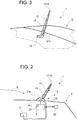
Figure 3 shows the mechanical structure of the device inFigure 1 . - The present invention will now be described in detail with reference to the attached figures to enable an expert in the field to embody it and use it. Various modifications to the described embodiments will be immediately obvious to experts in the field, and the generic principles described herein can be applied to other embodiments and applications without departing from the scope of the present invention, as defined in the appended claims. Therefore, the present invention should not be considered as limited to the embodiments set forth herein, but is to be accorded the widest scope consistent with the principles and features disclosed and claimed herein.
- In
Figure 1 ,reference numeral 1 indicates, as a whole, a visual locating device for amotor vehicle 2, in particular a passenger car (schematically and partially shown inFigures 2 and 3 ). - The locating
device 1 comprises: - a
light signal generator 4 coupled to anexternal antenna 5, of known type, of aradio system 7 of themotor vehicle 2; and - a
control circuit 9 operable to control, in response to an activation command S, the light signal thegenerator 4 to cause the latter to emit a light signal to facilitate visually locating the motor vehicle 2 (seeFigure 1 ). - Typically, the
antenna 5 extends upwards from the roof of the motor vehicle's body and comprises a straight elongatedinsulating element 11 containing the circuit portion of the antenna (of known type and not shown for simplicity). - According to the invention, the
light signal generator 4 comprises a plurality of LEDs (light emitting diodes) 4-L powered by a driving circuit (of known type and not shown for simplicity), and awaveguide 15 coupled to theantenna 5 to receive the optical signal generated by the LEDS 4-L. Thewaveguide 15 is made of a transparent material so that the optical signal generated by the LEDS 4-L is fed to the inlet of thewaveguide 15 and enables the illumination of at least part of thewaveguide 15, providing the aforementioned visual indication. - The optical signal can provide illumination for the entire length of the waveguide or illuminate one or more portions of the waveguide, for example, an end portion.
- The
waveguide 15 is made of a synthetic material and does not interfere with the electromagnetic structure of theantenna 5. Furthermore, even the LEDs 4-L do not effectively comprise materials that could cause electromagnetic interference with theantenna 5. - In this way, the problems of electromagnetic compatibility of devices pertaining to the known art are overcome.
- Furthermore, the visual locating
device 1 is extremely simple, robust, inexpensive and not subject to deterioration. - The
waveguide 15 comprises a singlestraight element 17, made of a synthetic material, which extends along theantenna 5 parallel to the axis ofantenna 5 and incorporates theantenna 5. - Alternatively, the
waveguide 15 can be coupled externally to theantenna 5; in this case, theantenna 5 is not contained inside the element made of a plastic material, which can be fastened to theantenna 5 by means of known connection systems, for example, snap-fit systems. - Furthermore, unlike that shown, the
waveguide 5 can have longitudinal dimensions smaller than those of theantenna 5, extending for just a section of theantenna 5. - The
straight element 17 of thewaveguide 15 has a widened base portion 17-B fastened to the motor vehicle's body by abase plate 18 and a tapered tip portion 17-R. Thebase plate 18 conveniently houses thecontrol circuit 9 and the LEDs 4-L. - According to the present invention, the
control circuit 9 comprises a set-up circuit 20 (Figure 2 ) for selection and adjustment of the light emission modes of thegenerator 4. - The set-
up circuit 20 is able to modify all of the following settings: - the emission colour of the light signal generated by the LEDs 4-L (i.e. several colours can be selected);
- the flash frequency of the light signal generated by the LEDs 4-L (i.e. several frequencies can be selected);
- the number of flashes of the light signal generated by the LEDs 4-L (i.e. the length of the light signal is adjustable); and
- the intensity of the light signal generated by the LEDs 4-L (i.e. the intensity of the light signal is adjustable).
- In this way, it is possible to change the characteristics of the light signal that facilitates locating the motor vehicle so that they are better suited to the environment where the motor vehicle is located.
- In motor vehicles equipped with an infotelematic system and/or infotainment system, the functions of the set-
up circuit 20 are conveniently implemented by the infotelematic system and/or infotainment system and can be activated both remotely by means of aremote control 10 and locally by means of the user interface of the infotelematic system and/or infotainment system. - Conveniently, the
remote control 10 can be implemented by means of a user's mobile phone and, consequently, thecontrol circuit 9 is interfaced with anonboard receiver device 22 capable of communicating with the mobile phone. - In particular, by using remote control implemented via a mobile phone of the smart-phone type (
Figure 1 ), it is possible to control an application for activating the visual locating device 1 (icon "M") and setting the parameters (icon "S") . - In alternative, the
remote control 10 is integrated in theignition key 12 of the motor vehicle. In this case, thekey 12 could be provided with a specific button "T" for generating the activation signal of the visual locatingdevice 1.
Claims (3)
- A visual locating device (1) for a motor vehicle (2), comprising:• an optoelectronic light signal generator (4) operable to emit a light signal; and• electronic control means (9) responsive to activation/setting commands to accordingly control the optoelectronic light signal generator (4) to cause emission of a light signal suitable to enable visually locating the motor vehicle (2);wherein the optoelectronic light signal generator (4) comprises:• an optoelectronic light source (4-L) operable to generate a light signal, and• a waveguide (15) configured to be mechanically coupleable with an external antenna (5) of the motor vehicle (2) to extend along at least part of the external antenna (5);
wherein the optoelectronic light source comprises a number of light emitting diodes (4-L);
wherein the waveguide (15) is configured to either enclose or be externally fastenable to, at least part the antenna (5),
wherein the waveguide (15) is made of optically transparent material that does not interfere with the electromagnetic structure of the antenna (5) and is configured to be optically coupleable with the optoelectronic light source (4-L) to receive a light signal therefrom and, resultingly, be at least partially illuminated thereby;
wherein the waveguide (15) comprises a substantially straight element (17) with a widened base portion (17-B) configured to be fastenable to a body part of the motor vehicle (2) via a base plate (18) where the optoelectronic light source (4-L) and the electronic control means (9), in form of a control circuit, are housed;
wherein the electronic control means (9) comprise user-controllable setting means (20) configured to cause all of the following quantities of the light signal generated by the optoelectronic light signal generator (4) to be user-settable both on the motor vehicle (2) and remotely therefrom:- light colour,- light intensity;- light flash frequency, and- number of light flashes,wherein the user-controllable setting means (20) are further configured to allow the user-settable quantities to be set via:- an on-vehicle user interface, and- a personal communication device;and wherein the electronic control means (9) are further configured to allow the optoelectronic light signal generator (4) to be remotely activated via:- a remote control (10) integrated in an ignition key (12) of the motor vehicle (2), and- a personal communication device into which the remote control (10) is implemented. - A visual locating device (1) according to claim 1, wherein the straight element (17) comprises a tapered tip portion (17-R).
- A motor vehicle (2) comprising an external antenna (5) and a visual locating device (1) according to any one of the preceding claims.
Applications Claiming Priority (2)
| Application Number | Priority Date | Filing Date | Title |
|---|---|---|---|
| IT000862A ITTO20120862A1 (en) | 2012-10-03 | 2012-10-03 | VISUAL LOCATION OF A MOTOR VEHICLE |
| PCT/IB2013/059099 WO2014054020A1 (en) | 2012-10-03 | 2013-10-03 | Visual locating device for a motor vehicle |
Publications (2)
| Publication Number | Publication Date |
|---|---|
| EP2903862A1 EP2903862A1 (en) | 2015-08-12 |
| EP2903862B1 true EP2903862B1 (en) | 2020-08-12 |
Family
ID=47324293
Family Applications (1)
| Application Number | Title | Priority Date | Filing Date |
|---|---|---|---|
| EP13803240.4A Active EP2903862B1 (en) | 2012-10-03 | 2013-10-03 | Visual locating device for a motor vehicle |
Country Status (4)
| Country | Link |
|---|---|
| US (1) | US9373260B2 (en) |
| EP (1) | EP2903862B1 (en) |
| IT (1) | ITTO20120862A1 (en) |
| WO (1) | WO2014054020A1 (en) |
Families Citing this family (9)
| Publication number | Priority date | Publication date | Assignee | Title |
|---|---|---|---|---|
| FR3029605B1 (en) * | 2014-12-03 | 2016-12-30 | Peugeot Citroen Automobiles Sa | MOBILE HOST LIGHTING AND / OR SIGNALING DEVICE FOR A MOTOR VEHICLE ASSOCIATED WITH THE LOCATION OF THE VEHICLE |
| US20160379532A1 (en) * | 2015-06-25 | 2016-12-29 | Lauresa Tomlinson | Vehicle location assistance assembly |
| FR3056501B1 (en) * | 2016-09-28 | 2020-05-29 | Valeo Vision | ASSISTANCE SYSTEM FOR THE IDENTIFICATION OF A MOTOR VEHICLE AND ITS IMPLEMENTATION METHOD |
| US10176719B1 (en) * | 2017-09-23 | 2019-01-08 | John Jackson | System for locating a parked vehicle |
| TW201917043A (en) * | 2017-10-24 | 2019-05-01 | 大昱光電股份有限公司 | Automobile light emitting device |
| FR3087398A1 (en) * | 2018-10-18 | 2020-04-24 | Christian Jean Felix Antoine Lafon | DEVICE FOR FACILITATING THE MARKING OF A VEHICLE IN A PARKING |
| US11772549B2 (en) * | 2021-03-19 | 2023-10-03 | Claudia Roque | Remote-control device and method for locating a parked vehicle |
| US11634314B1 (en) | 2022-11-17 | 2023-04-25 | Sharkninja Operating Llc | Dosing accuracy |
| EP4395070A1 (en) * | 2022-12-30 | 2024-07-03 | Aptiv Technologies AG | Integrated vehicle antenna indicator system |
Family Cites Families (14)
| Publication number | Priority date | Publication date | Assignee | Title |
|---|---|---|---|---|
| US3506956A (en) * | 1968-04-10 | 1970-04-14 | Sonus Corp | Automobile recognition system |
| US4011443A (en) * | 1974-09-16 | 1977-03-08 | Smith Merle F | Motorcycle indicating safety light assembly |
| US4797671A (en) * | 1987-01-15 | 1989-01-10 | Toal Jr Robert P | Motor vehicle locator system |
| US6126303A (en) * | 1994-09-09 | 2000-10-03 | Enterprises, Inc. | Illuminated car locator |
| US5933091A (en) | 1996-08-12 | 1999-08-03 | Mccaslin; Robert E. | Remotely-actuated infrared-sensitive switch |
| US5933081A (en) * | 1998-05-05 | 1999-08-03 | Antenna Buddies, Inc. | Device for aiding in the location of an automobile |
| US6239701B1 (en) | 1999-09-07 | 2001-05-29 | Michael Vasquez | Vehicle locator light |
| US6580368B1 (en) | 2000-06-06 | 2003-06-17 | Adam Jacobs | Vehicle locator device |
| US20040164861A1 (en) * | 2003-02-25 | 2004-08-26 | Rawson Dennis G. | Antenna-mounted vehicle location system |
| DE102004041245A1 (en) | 2004-08-26 | 2006-03-02 | Robert Bosch Gmbh | Arrangement for displaying a vehicle location |
| US7369061B1 (en) * | 2004-10-05 | 2008-05-06 | Steven Sellers | Vehicle locator device |
| US7119679B1 (en) | 2004-12-03 | 2006-10-10 | Crom Eugene F | Vehicle locating apparatus |
| DE202006009591U1 (en) * | 2006-06-20 | 2006-10-05 | Özkan, Volkan | Motor vehicle antenna, has LEDs mounted for producing flashing or non-flashing light |
| DE202011004301U1 (en) * | 2011-03-21 | 2011-07-29 | Thanh-Son Le | Car remote discovery |
-
2012
- 2012-10-03 IT IT000862A patent/ITTO20120862A1/en unknown
-
2013
- 2013-10-03 EP EP13803240.4A patent/EP2903862B1/en active Active
- 2013-10-03 US US14/432,981 patent/US9373260B2/en active Active
- 2013-10-03 WO PCT/IB2013/059099 patent/WO2014054020A1/en not_active Ceased
Non-Patent Citations (1)
| Title |
|---|
| None * |
Also Published As
| Publication number | Publication date |
|---|---|
| ITTO20120862A1 (en) | 2014-04-04 |
| US9373260B2 (en) | 2016-06-21 |
| WO2014054020A8 (en) | 2014-07-31 |
| US20150254980A1 (en) | 2015-09-10 |
| EP2903862A1 (en) | 2015-08-12 |
| WO2014054020A1 (en) | 2014-04-10 |
Similar Documents
| Publication | Publication Date | Title |
|---|---|---|
| US9373260B2 (en) | Visual locating device for a motor vehicle | |
| US10005387B2 (en) | Vehicle locator system | |
| US8414168B2 (en) | Roof rack assembly with integrated lighting | |
| US10371324B2 (en) | Single color or multiple color LED angel eyes halo headlight | |
| US10836306B1 (en) | Vehicle with portable signature light assembly | |
| KR20210090725A (en) | Reinforcement of vehicle emergency system | |
| EP3671018B1 (en) | Vehicle winglet, sequential blinker assembly and system for sequentially illuminating regions of a vehicle winglet | |
| CA2695245A1 (en) | Lighting system | |
| US20090213602A1 (en) | Light-emitting device for the interior of a vehicle with music synchronization | |
| WO2006047513A2 (en) | Auxiliary safety light system | |
| US9589746B2 (en) | Switch device for vehicular air conditioning system | |
| CN107525032A (en) | Lighting module for motor vehicles | |
| US7276854B1 (en) | Decorative lamp and lighting system for vehicles | |
| JP3149542U (en) | Bicycle traveling assistance device | |
| US20020171536A1 (en) | Signalling arrangement for vehicle, in particular motor vehicle, locking circuit | |
| KR101305782B1 (en) | emergency signal apparatus for vehicles | |
| KR101858722B1 (en) | Air floating type traffic accident notification device | |
| US20060028349A1 (en) | LED indicator set with radio signal transmitter | |
| KR101273388B1 (en) | Portable led emergency light and method for controlling the same | |
| KR20100063350A (en) | Luminous car wheel | |
| CN206633945U (en) | A kind of control device of wireless on automobile | |
| US12601471B1 (en) | Illuminable badge assembly of motor vehicle | |
| KR101130763B1 (en) | The Model Equipment for Ornmental and Real Time Detects Arcing of a Lamp | |
| CN218237122U (en) | Electric torch for vehicle | |
| KR20240148644A (en) | AML Control Box |
Legal Events
| Date | Code | Title | Description |
|---|---|---|---|
| PUAI | Public reference made under article 153(3) epc to a published international application that has entered the european phase |
Free format text: ORIGINAL CODE: 0009012 |
|
| 17P | Request for examination filed |
Effective date: 20150415 |
|
| AK | Designated contracting states |
Kind code of ref document: A1 Designated state(s): AL AT BE BG CH CY CZ DE DK EE ES FI FR GB GR HR HU IE IS IT LI LT LU LV MC MK MT NL NO PL PT RO RS SE SI SK SM TR |
|
| AX | Request for extension of the european patent |
Extension state: BA ME |
|
| DAX | Request for extension of the european patent (deleted) | ||
| GRAP | Despatch of communication of intention to grant a patent |
Free format text: ORIGINAL CODE: EPIDOSNIGR1 |
|
| STAA | Information on the status of an ep patent application or granted ep patent |
Free format text: STATUS: GRANT OF PATENT IS INTENDED |
|
| INTG | Intention to grant announced |
Effective date: 20200305 |
|
| GRAS | Grant fee paid |
Free format text: ORIGINAL CODE: EPIDOSNIGR3 |
|
| GRAA | (expected) grant |
Free format text: ORIGINAL CODE: 0009210 |
|
| STAA | Information on the status of an ep patent application or granted ep patent |
Free format text: STATUS: THE PATENT HAS BEEN GRANTED |
|
| AK | Designated contracting states |
Kind code of ref document: B1 Designated state(s): AL AT BE BG CH CY CZ DE DK EE ES FI FR GB GR HR HU IE IS IT LI LT LU LV MC MK MT NL NO PL PT RO RS SE SI SK SM TR |
|
| REG | Reference to a national code |
Ref country code: CH Ref legal event code: EP |
|
| REG | Reference to a national code |
Ref country code: IE Ref legal event code: FG4D |
|
| REG | Reference to a national code |
Ref country code: DE Ref legal event code: R096 Ref document number: 602013071600 Country of ref document: DE |
|
| REG | Reference to a national code |
Ref country code: AT Ref legal event code: REF Ref document number: 1301247 Country of ref document: AT Kind code of ref document: T Effective date: 20200915 |
|
| REG | Reference to a national code |
Ref country code: LT Ref legal event code: MG4D |
|
| REG | Reference to a national code |
Ref country code: NL Ref legal event code: MP Effective date: 20200812 |
|
| PG25 | Lapsed in a contracting state [announced via postgrant information from national office to epo] |
Ref country code: HR Free format text: LAPSE BECAUSE OF FAILURE TO SUBMIT A TRANSLATION OF THE DESCRIPTION OR TO PAY THE FEE WITHIN THE PRESCRIBED TIME-LIMIT Effective date: 20200812 Ref country code: SE Free format text: LAPSE BECAUSE OF FAILURE TO SUBMIT A TRANSLATION OF THE DESCRIPTION OR TO PAY THE FEE WITHIN THE PRESCRIBED TIME-LIMIT Effective date: 20200812 Ref country code: FI Free format text: LAPSE BECAUSE OF FAILURE TO SUBMIT A TRANSLATION OF THE DESCRIPTION OR TO PAY THE FEE WITHIN THE PRESCRIBED TIME-LIMIT Effective date: 20200812 Ref country code: LT Free format text: LAPSE BECAUSE OF FAILURE TO SUBMIT A TRANSLATION OF THE DESCRIPTION OR TO PAY THE FEE WITHIN THE PRESCRIBED TIME-LIMIT Effective date: 20200812 Ref country code: BG Free format text: LAPSE BECAUSE OF FAILURE TO SUBMIT A TRANSLATION OF THE DESCRIPTION OR TO PAY THE FEE WITHIN THE PRESCRIBED TIME-LIMIT Effective date: 20201112 Ref country code: GR Free format text: LAPSE BECAUSE OF FAILURE TO SUBMIT A TRANSLATION OF THE DESCRIPTION OR TO PAY THE FEE WITHIN THE PRESCRIBED TIME-LIMIT Effective date: 20201113 Ref country code: ES Free format text: LAPSE BECAUSE OF FAILURE TO SUBMIT A TRANSLATION OF THE DESCRIPTION OR TO PAY THE FEE WITHIN THE PRESCRIBED TIME-LIMIT Effective date: 20200812 Ref country code: NO Free format text: LAPSE BECAUSE OF FAILURE TO SUBMIT A TRANSLATION OF THE DESCRIPTION OR TO PAY THE FEE WITHIN THE PRESCRIBED TIME-LIMIT Effective date: 20201112 |
|
| REG | Reference to a national code |
Ref country code: AT Ref legal event code: MK05 Ref document number: 1301247 Country of ref document: AT Kind code of ref document: T Effective date: 20200812 |
|
| PG25 | Lapsed in a contracting state [announced via postgrant information from national office to epo] |
Ref country code: IS Free format text: LAPSE BECAUSE OF FAILURE TO SUBMIT A TRANSLATION OF THE DESCRIPTION OR TO PAY THE FEE WITHIN THE PRESCRIBED TIME-LIMIT Effective date: 20201212 Ref country code: NL Free format text: LAPSE BECAUSE OF FAILURE TO SUBMIT A TRANSLATION OF THE DESCRIPTION OR TO PAY THE FEE WITHIN THE PRESCRIBED TIME-LIMIT Effective date: 20200812 Ref country code: RS Free format text: LAPSE BECAUSE OF FAILURE TO SUBMIT A TRANSLATION OF THE DESCRIPTION OR TO PAY THE FEE WITHIN THE PRESCRIBED TIME-LIMIT Effective date: 20200812 Ref country code: PL Free format text: LAPSE BECAUSE OF FAILURE TO SUBMIT A TRANSLATION OF THE DESCRIPTION OR TO PAY THE FEE WITHIN THE PRESCRIBED TIME-LIMIT Effective date: 20200812 Ref country code: LV Free format text: LAPSE BECAUSE OF FAILURE TO SUBMIT A TRANSLATION OF THE DESCRIPTION OR TO PAY THE FEE WITHIN THE PRESCRIBED TIME-LIMIT Effective date: 20200812 |
|
| PG25 | Lapsed in a contracting state [announced via postgrant information from national office to epo] |
Ref country code: CZ Free format text: LAPSE BECAUSE OF FAILURE TO SUBMIT A TRANSLATION OF THE DESCRIPTION OR TO PAY THE FEE WITHIN THE PRESCRIBED TIME-LIMIT Effective date: 20200812 Ref country code: DK Free format text: LAPSE BECAUSE OF FAILURE TO SUBMIT A TRANSLATION OF THE DESCRIPTION OR TO PAY THE FEE WITHIN THE PRESCRIBED TIME-LIMIT Effective date: 20200812 Ref country code: EE Free format text: LAPSE BECAUSE OF FAILURE TO SUBMIT A TRANSLATION OF THE DESCRIPTION OR TO PAY THE FEE WITHIN THE PRESCRIBED TIME-LIMIT Effective date: 20200812 Ref country code: RO Free format text: LAPSE BECAUSE OF FAILURE TO SUBMIT A TRANSLATION OF THE DESCRIPTION OR TO PAY THE FEE WITHIN THE PRESCRIBED TIME-LIMIT Effective date: 20200812 Ref country code: SM Free format text: LAPSE BECAUSE OF FAILURE TO SUBMIT A TRANSLATION OF THE DESCRIPTION OR TO PAY THE FEE WITHIN THE PRESCRIBED TIME-LIMIT Effective date: 20200812 |
|
| REG | Reference to a national code |
Ref country code: DE Ref legal event code: R097 Ref document number: 602013071600 Country of ref document: DE |
|
| PG25 | Lapsed in a contracting state [announced via postgrant information from national office to epo] |
Ref country code: AL Free format text: LAPSE BECAUSE OF FAILURE TO SUBMIT A TRANSLATION OF THE DESCRIPTION OR TO PAY THE FEE WITHIN THE PRESCRIBED TIME-LIMIT Effective date: 20200812 Ref country code: AT Free format text: LAPSE BECAUSE OF FAILURE TO SUBMIT A TRANSLATION OF THE DESCRIPTION OR TO PAY THE FEE WITHIN THE PRESCRIBED TIME-LIMIT Effective date: 20200812 |
|
| REG | Reference to a national code |
Ref country code: CH Ref legal event code: PL |
|
| PLBE | No opposition filed within time limit |
Free format text: ORIGINAL CODE: 0009261 |
|
| STAA | Information on the status of an ep patent application or granted ep patent |
Free format text: STATUS: NO OPPOSITION FILED WITHIN TIME LIMIT |
|
| PG25 | Lapsed in a contracting state [announced via postgrant information from national office to epo] |
Ref country code: MC Free format text: LAPSE BECAUSE OF FAILURE TO SUBMIT A TRANSLATION OF THE DESCRIPTION OR TO PAY THE FEE WITHIN THE PRESCRIBED TIME-LIMIT Effective date: 20200812 Ref country code: SK Free format text: LAPSE BECAUSE OF FAILURE TO SUBMIT A TRANSLATION OF THE DESCRIPTION OR TO PAY THE FEE WITHIN THE PRESCRIBED TIME-LIMIT Effective date: 20200812 Ref country code: LU Free format text: LAPSE BECAUSE OF NON-PAYMENT OF DUE FEES Effective date: 20201003 |
|
| REG | Reference to a national code |
Ref country code: BE Ref legal event code: MM Effective date: 20201031 |
|
| 26N | No opposition filed |
Effective date: 20210514 |
|
| GBPC | Gb: european patent ceased through non-payment of renewal fee |
Effective date: 20201112 |
|
| PG25 | Lapsed in a contracting state [announced via postgrant information from national office to epo] |
Ref country code: LI Free format text: LAPSE BECAUSE OF NON-PAYMENT OF DUE FEES Effective date: 20201031 Ref country code: SI Free format text: LAPSE BECAUSE OF FAILURE TO SUBMIT A TRANSLATION OF THE DESCRIPTION OR TO PAY THE FEE WITHIN THE PRESCRIBED TIME-LIMIT Effective date: 20200812 Ref country code: CH Free format text: LAPSE BECAUSE OF NON-PAYMENT OF DUE FEES Effective date: 20201031 Ref country code: BE Free format text: LAPSE BECAUSE OF NON-PAYMENT OF DUE FEES Effective date: 20201031 |
|
| PG25 | Lapsed in a contracting state [announced via postgrant information from national office to epo] |
Ref country code: IE Free format text: LAPSE BECAUSE OF NON-PAYMENT OF DUE FEES Effective date: 20201003 |
|
| PG25 | Lapsed in a contracting state [announced via postgrant information from national office to epo] |
Ref country code: GB Free format text: LAPSE BECAUSE OF NON-PAYMENT OF DUE FEES Effective date: 20201112 |
|
| PG25 | Lapsed in a contracting state [announced via postgrant information from national office to epo] |
Ref country code: IS Free format text: LAPSE BECAUSE OF FAILURE TO SUBMIT A TRANSLATION OF THE DESCRIPTION OR TO PAY THE FEE WITHIN THE PRESCRIBED TIME-LIMIT Effective date: 20201212 Ref country code: TR Free format text: LAPSE BECAUSE OF FAILURE TO SUBMIT A TRANSLATION OF THE DESCRIPTION OR TO PAY THE FEE WITHIN THE PRESCRIBED TIME-LIMIT Effective date: 20200812 Ref country code: MT Free format text: LAPSE BECAUSE OF FAILURE TO SUBMIT A TRANSLATION OF THE DESCRIPTION OR TO PAY THE FEE WITHIN THE PRESCRIBED TIME-LIMIT Effective date: 20200812 Ref country code: CY Free format text: LAPSE BECAUSE OF FAILURE TO SUBMIT A TRANSLATION OF THE DESCRIPTION OR TO PAY THE FEE WITHIN THE PRESCRIBED TIME-LIMIT Effective date: 20200812 |
|
| PG25 | Lapsed in a contracting state [announced via postgrant information from national office to epo] |
Ref country code: MK Free format text: LAPSE BECAUSE OF FAILURE TO SUBMIT A TRANSLATION OF THE DESCRIPTION OR TO PAY THE FEE WITHIN THE PRESCRIBED TIME-LIMIT Effective date: 20200812 |
|
| PG25 | Lapsed in a contracting state [announced via postgrant information from national office to epo] |
Ref country code: PT Free format text: LAPSE BECAUSE OF FAILURE TO SUBMIT A TRANSLATION OF THE DESCRIPTION OR TO PAY THE FEE WITHIN THE PRESCRIBED TIME-LIMIT Effective date: 20200812 |
|
| PGFP | Annual fee paid to national office [announced via postgrant information from national office to epo] |
Ref country code: FR Payment date: 20240919 Year of fee payment: 12 |
|
| PGFP | Annual fee paid to national office [announced via postgrant information from national office to epo] |
Ref country code: IT Payment date: 20240919 Year of fee payment: 12 |
|
| PGFP | Annual fee paid to national office [announced via postgrant information from national office to epo] |
Ref country code: DE Payment date: 20240919 Year of fee payment: 12 |