EP2903840B1 - Suspension for a wheeled vehicle - Google Patents
Suspension for a wheeled vehicle Download PDFInfo
- Publication number
- EP2903840B1 EP2903840B1 EP13805508.2A EP13805508A EP2903840B1 EP 2903840 B1 EP2903840 B1 EP 2903840B1 EP 13805508 A EP13805508 A EP 13805508A EP 2903840 B1 EP2903840 B1 EP 2903840B1
- Authority
- EP
- European Patent Office
- Prior art keywords
- chamber
- cylinder
- suspension
- spring
- gas
- Prior art date
- Legal status (The legal status is an assumption and is not a legal conclusion. Google has not performed a legal analysis and makes no representation as to the accuracy of the status listed.)
- Active
Links
Images

Classifications
-
- B—PERFORMING OPERATIONS; TRANSPORTING
- B60—VEHICLES IN GENERAL
- B60G—VEHICLE SUSPENSION ARRANGEMENTS
- B60G11/00—Resilient suspensions characterised by arrangement, location or kind of springs
- B60G11/32—Resilient suspensions characterised by arrangement, location or kind of springs having springs of different kinds
- B60G11/48—Resilient suspensions characterised by arrangement, location or kind of springs having springs of different kinds not including leaf springs
- B60G11/56—Resilient suspensions characterised by arrangement, location or kind of springs having springs of different kinds not including leaf springs having helical, spiral or coil springs, and also fluid springs
-
- B—PERFORMING OPERATIONS; TRANSPORTING
- B60—VEHICLES IN GENERAL
- B60G—VEHICLE SUSPENSION ARRANGEMENTS
- B60G15/00—Resilient suspensions characterised by arrangement, location or type of combined spring and vibration damper, e.g. telescopic type
- B60G15/02—Resilient suspensions characterised by arrangement, location or type of combined spring and vibration damper, e.g. telescopic type having mechanical spring
- B60G15/06—Resilient suspensions characterised by arrangement, location or type of combined spring and vibration damper, e.g. telescopic type having mechanical spring and fluid damper
- B60G15/062—Resilient suspensions characterised by arrangement, location or type of combined spring and vibration damper, e.g. telescopic type having mechanical spring and fluid damper the spring being arranged around the damper
- B60G15/063—Resilient suspensions characterised by arrangement, location or type of combined spring and vibration damper, e.g. telescopic type having mechanical spring and fluid damper the spring being arranged around the damper characterised by the mounting of the spring on the damper
-
- B—PERFORMING OPERATIONS; TRANSPORTING
- B60—VEHICLES IN GENERAL
- B60G—VEHICLE SUSPENSION ARRANGEMENTS
- B60G17/00—Resilient suspensions having means for adjusting the spring or vibration-damper characteristics, for regulating the distance between a supporting surface and a sprung part of vehicle or for locking suspension during use to meet varying vehicular or surface conditions, e.g. due to speed or load
- B60G17/02—Spring characteristics, e.g. mechanical springs and mechanical adjusting means
- B60G17/027—Mechanical springs regulated by fluid means
- B60G17/0272—Mechanical springs regulated by fluid means the mechanical spring being a coil spring
-
- B—PERFORMING OPERATIONS; TRANSPORTING
- B60—VEHICLES IN GENERAL
- B60G—VEHICLE SUSPENSION ARRANGEMENTS
- B60G17/00—Resilient suspensions having means for adjusting the spring or vibration-damper characteristics, for regulating the distance between a supporting surface and a sprung part of vehicle or for locking suspension during use to meet varying vehicular or surface conditions, e.g. due to speed or load
- B60G17/02—Spring characteristics, e.g. mechanical springs and mechanical adjusting means
- B60G17/04—Spring characteristics, e.g. mechanical springs and mechanical adjusting means fluid spring characteristics
- B60G17/0416—Spring characteristics, e.g. mechanical springs and mechanical adjusting means fluid spring characteristics regulated by varying the resiliency of hydropneumatic suspensions
- B60G17/0424—Spring characteristics, e.g. mechanical springs and mechanical adjusting means fluid spring characteristics regulated by varying the resiliency of hydropneumatic suspensions by varying the air pressure of the accumulator
-
- B—PERFORMING OPERATIONS; TRANSPORTING
- B60—VEHICLES IN GENERAL
- B60G—VEHICLE SUSPENSION ARRANGEMENTS
- B60G2202/00—Indexing codes relating to the type of spring, damper or actuator
- B60G2202/10—Type of spring
- B60G2202/12—Wound spring
-
- B—PERFORMING OPERATIONS; TRANSPORTING
- B60—VEHICLES IN GENERAL
- B60G—VEHICLE SUSPENSION ARRANGEMENTS
- B60G2202/00—Indexing codes relating to the type of spring, damper or actuator
- B60G2202/10—Type of spring
- B60G2202/15—Fluid spring
- B60G2202/154—Fluid spring with an accumulator
-
- B—PERFORMING OPERATIONS; TRANSPORTING
- B60—VEHICLES IN GENERAL
- B60G—VEHICLE SUSPENSION ARRANGEMENTS
- B60G2202/00—Indexing codes relating to the type of spring, damper or actuator
- B60G2202/30—Spring/Damper and/or actuator Units
- B60G2202/31—Spring/Damper and/or actuator Units with the spring arranged around the damper, e.g. MacPherson strut
- B60G2202/312—The spring being a wound spring
-
- B—PERFORMING OPERATIONS; TRANSPORTING
- B60—VEHICLES IN GENERAL
- B60G—VEHICLE SUSPENSION ARRANGEMENTS
- B60G2202/00—Indexing codes relating to the type of spring, damper or actuator
- B60G2202/40—Type of actuator
- B60G2202/41—Fluid actuator
- B60G2202/412—Pneumatic actuator
-
- B—PERFORMING OPERATIONS; TRANSPORTING
- B60—VEHICLES IN GENERAL
- B60G—VEHICLE SUSPENSION ARRANGEMENTS
- B60G2204/00—Indexing codes related to suspensions per se or to auxiliary parts
- B60G2204/10—Mounting of suspension elements
- B60G2204/12—Mounting of springs or dampers
- B60G2204/124—Mounting of coil springs
- B60G2204/1242—Mounting of coil springs on a damper, e.g. MacPerson strut
-
- B—PERFORMING OPERATIONS; TRANSPORTING
- B60—VEHICLES IN GENERAL
- B60G—VEHICLE SUSPENSION ARRANGEMENTS
- B60G2400/00—Indexing codes relating to detected, measured or calculated conditions or factors
- B60G2400/25—Stroke; Height; Displacement
- B60G2400/252—Stroke; Height; Displacement vertical
-
- B—PERFORMING OPERATIONS; TRANSPORTING
- B60—VEHICLES IN GENERAL
- B60G—VEHICLE SUSPENSION ARRANGEMENTS
- B60G2500/00—Indexing codes relating to the regulated action or device
- B60G2500/20—Spring action or springs
-
- B—PERFORMING OPERATIONS; TRANSPORTING
- B60—VEHICLES IN GENERAL
- B60G—VEHICLE SUSPENSION ARRANGEMENTS
- B60G2500/00—Indexing codes relating to the regulated action or device
- B60G2500/30—Height or ground clearance
Definitions
- the present invention relates to a suspension for wheeled vehicles.
- the present invention is used in the automotive and motorcycle field.
- suspensions for vehicles which comprise a fluidic damper that is constrained between at least the wheel and the frame of the vehicle and provided with a cylinder and a piston sliding within said cylinder, and one spring element, such as a coil spring, coupleable to said fluidic damper coaxially to the latter, for the transmission of loads between the wheel and the frame when the position of said piston with respect to said cylinder changes.
- vehicle suspensions have to accomplish several operations, such as to absorb the ground bumps, limit the side movements of the vehicle and uniformly distribute the loads on the wheels.
- the spring plays a substantial role, having just the function of transmitting the loads between the vehicle wheel and frame to ensure a greater comfort of passengers.
- This system provides a passive control of the spring modulus based on the position and have a curve following the progressiveness of the air spring but as reliable as a coil spring.
- the price that has to be paid for this system is still the lack of versatility and adaptability, because it is necessary to replace one or more springs to change the suspension feature.
- this solution makes very difficult to change the vehicle ground clearance without replacing one or more of the spring elements.
- JP S59 165287 U discloses a motorbike suspension system that comprises a forward suspension and a rearward suspension.
- JP 2007 0300660 A discloses a vehicle height adjusting system which can improve a riding feeling by reducing frictions and can reduce the volume and the weight of the overall system.
- JP S58 26612 A relates to a car level which is automatically controlled in accordance with a car running state, by producing compressed oil in a hydraulic pump house by dint of an external vibration output.
- DE102005008814 A1 relates to a hydraulic height adjustment for a motor vehicle landing gear, in particular for a spring strut with spiral spring and damping unit. It is therefore an object of the present invention to provide a suspension, alternatively to the others above mentioned systems, ensuring at the same time a high comfort and a limited car roll in all traveling conditions of the car and any type of road the car is facing.
- Another object is to provide a suspension that is simple, reliable and with a greater versatility with respect to the suspensions of the known art, provided with known means for changing the law of transmission of loads of the spring element.
- the present suspension for a wheeled vehicle comprising at least one fluidic damper constrained between at least one wheel and the frame of said vehicle and provided with a cylinder and a piston sliding within said cylinder, at least one spring element coupleable to said fluidic damper for the transmission of loads between said at least one wheel and said frame when the position of said piston with respect to said cylinder changes, and means for changing the law of transmission of loads of said at least one spring element when the position of said piston relative to said cylinder changes, characterized in that said means for changing the law of transmission of loads comprise at least one gas spring operatively coupled in series to said at least one spring element and acting for at least part of the stroke of said piston relative to said cylinder, said at least one gas spring being fluidically independent from said at least one fluidic damper.
- the suspension comprises a spring element, or main spring, such as a coil spring, preferably having a high, but nevertheless constant or predetermined, spring modulus operatively placed in series with an air spring, preferably having a travel smaller than the spring element and anyway with a variable spring modulus based on the relative displacement of piston and cylinder of the fluidic damper, based as well on the volume and initial pressure of the gas spring itself.
- a spring element such as a coil spring
- main spring such as a coil spring
- an air spring preferably having a travel smaller than the spring element and anyway with a variable spring modulus based on the relative displacement of piston and cylinder of the fluidic damper, based as well on the volume and initial pressure of the gas spring itself.
- the means for changing the law of transmission of loads of the spring element allow to change the overall spring modulus K of the suspension, so that the inverse of the spring modulus of the coil spring, that is to say 1/k1, is added to the inverse of the spring modulus k2 of the gas spring, whose value changes based on the position of the piston relative to the cylinder of the damper.
- the spring modulus k2 represented by a curve that changes based on the piston displacement with respect to the cylinder of the damper, also depends on the initial volume (Vo) and initial pressure (Po), as well as on a reference surface inside the gas spring itself. On the contrary, such a spring modulus is completely independent from the geometry of the fluidic damper.
- This suspension is as versatile as a suspension having only one air spring, because we can obtain an unlimited range of characteristic curves of load transmission by changing the air pressure and volume included in said gas spring, without replacing any part. Additionally, together with the above mentioned advantages, the suspension has a simple structure and a high safety degree since in case of air leakage of the gas spring, the car would be anyway supported by coil springs, therefore the suspensions would act as the traditional one.
- the gas spring is fluidically independent from said at least one fluidic damper. Basically, when the oil inside the damper moves, during the piston displacement with respect to the cylinder, the gas spring operation is not affected, the two elements being structurally separated.
- the coefficient c would in any case depend on K(x) as well. Therefore, the coefficient c would be a function of both dx/dt and K(x). This dependency condition is difficult to analyze, and, anyway, it would be difficult to control.
- K(x) is completely independent from the fluidic damper geometry, as the reference surface where the air spring pressure acts is inside the spring itself and it does not affect the damper components.
- said at least one gas spring comprises at least one first chamber containing a gas.
- Said at least one first chamber is provided with at least one wall, or separator, which is sliding, or deformable, within said at least one first chamber based on the position of said piston relative to said cylinder, to change the gas volume, or pressure, inside said at least one first chamber.
- said at least one gas spring comprises as well at least one second and one third chamber fluidically communicating with each other and containing an incompressible fluid, wherein said at least one third chamber is provided with at least one first portion directly or indirectly connected to said cylinder, and one second portion constrained movable sealingly with respect to said at least one first portion to transfer said incompressible fluid between said at least one second chamber and said at least one third chamber, and vice versa, when the position of said piston relative to said cylinder changes.
- the incompressible fluid transferred from said at least one second chamber and said at least one third chamber never contacts the fluid that is inside the damper and that is moved by the piston when it slides inside the cylinder and never transfers the pressure of said at least one second and at least one third chambers to the damper components.
- the gas spring is fluidically independent from said at least one fluidic damper.
- said at least one partition wall is also sliding, or deformable, within said at least one first chamber and within said at least one second chamber, based on the volume of incompressible fluid transferred from said at least one second chamber to said at least one third chamber, and vice versa.
- said at least one first and said at least one second chamber are formed inside a tank and said at least one wall is sliding, or deformable, inside said tank to define at least said one first chamber and said at least one second chamber.
- this solution makes not necessary to provide for a gas spring sealed against gas leakages by means of two reciprocally moving parts to compress a gas.
- said at least one second chamber and said at least one third chamber allows to realize a gas spring whose sealing problems are transferred to said first and second portion of said at least one third chamber housing, as mentioned, a liquid and not a gas.
- said at least one first portion and said at least one second portion of said at least one third chamber are arranged coaxially to said fluidic damper, as well as said spring element.
- the third chamber is substantially annular-shaped and said at least one first portion comprises at least one first hollow sleeve and said at least one second portion comprises at least one second hollow sleeve shaped to sealingly slide with respect to said at least one first hollow sleeve.
- said at least one first portion has a zone constrained by interference to said cylinder of said damper.
- said at least one spring element has an end abutting against said at least one second portion of said at least one third chamber.
- the travel of the gas spring is smaller than that of the spring element.
- said gas spring comprises at least one duct for fluidically connecting said at least one second chamber with said at least one third chamber in order to transfer said incompressible fluid between said at least one second chamber and said at least one third chamber, and vice versa.
- the suspension also comprises first means for adjusting the gas input/output to/from said at least one first chamber.
- Said first adjusting means comprise at least one valve, fluidically connected with said at least one first chamber, and a system for the air inflow/ outflow to/from said at least one first chamber.
- the suspension also comprises second means for adjusting the input/output of said incompressible fluid to/from said at least one second and third chamber.
- Said second adjusting means comprise at least one valve fluidically connected with said connecting duct, or said at least one second chamber or said at least one third chamber, and a second system for inflow/ outflow of said incompressible fluid from/to said at least one connecting duct.
- any portion of the volume got inside said one first chamber maybe introduced, the chamber containing gas, such that it is possible to independently control the available stroke of the gas spring and, accordingly, the ground clearance of the vehicle.
- the suspension according to the invention an unlimited amount of force-displacement characteristic curves of the suspension can be obtained by adjusting the initial pressure and the volume of the oil introduced in the circuit, not only during the tuning but also dynamically without replacing any mechanical component. In this way, it is possible to have a very wide range of characteristic curves that allow to adapt a car to any operating condition, either totally comfort-oriented or sport-oriented; on road or off road.
- the suspension object of the present invention allows therefore to easily and reliably adjust the spring modulus based on the position of the damper.
- the suspension allows to independently adjust its force-displacement characteristic curve and the vehicle ground clearance without replacing any mechanical part, easily and reliably.
- the oil inlet valve can be used to adjust the initial position of the piston, and therefore the vehicle ground clearance, in a range defined by the maximum travel of the cylinder-piston system.
- the maximum travel of the cylinder- piston system is a fraction of the overall travel of the suspension.
- the remaining part of the suspension travel is absorbed by a coil spring with a constant modulus operatively placed in series with said gas spring, ensuring the total reliability of the suspension in case of breakage of said gas spring.
- the suspension which can be defined as a mix of a suspension provided with only a coil spring and a suspension provided with only a gas spring, allows to obtain a very wide range of characteristic curves, acting as a hydro pneumatic suspension in terms of progressiveness and versatility, but being as reliable as a coil spring suspension.
- this hybrid system can allow an active control of the suspension by way of one or more sensors, able to immediately control the suspension feature so as to dynamically obtain the change of air volume and/or pressure present inside said first chamber, or the volume of oil, or a similar liquid, present inside said at least one second and third chamber.
- the objects of the present invention are achieved, as well, by the only means for changing the law of transmission of loads for at least one spring element of a suspension comprising at least one fluidic damper provided with a cylinder and a piston sliding inside said cylinder, wherein said at least one spring element is coupleable to said fluidic damper to transmit loads between said at least one wheel and said frame when the position of said piston with respect to said cylinder changes, characterized by comprising at least one gas spring operatively coupled in series to said at least one spring element and acting for at least part of said piston stroke relative to said cylinder, wherein said at least one spring is fluidically independent from said at least one fluidic damper.
- numeral 1 is shown a container according to the invention.
- the suspension 1 for a wheeled vehicle comprises a fluidic damper 2 constrained between a wheel 50 and the frame 51 of said vehicle (herein not shown) and provided with a cylinder 3 and a piston 4 sliding within said cylinder 3 and a spring element 5, for example a coil spring, coupleable to said fluidic damper 2 for the transmission of loads between said wheel 50 and said frame 51 when the position of said piston 4 with respect to said cylinder 3 changes.
- Said coil spring 5 is coaxial to said fluidic damper 2.
- said suspension 1 comprises means 6 for changing the law of transmission of loads of said spring element 5 when the position of said piston 4 relative to said cylinder 3 changes.
- Said means 6 for changing the law of transmission of loads comprise a gas spring 7 operatively coupled in series to said spring element 5 and acting for at least part of the stroke of said piston 4 relative to said cylinder 3.
- said gas spring 7 comprises a first chamber 8 containing a gas, particularly air, and is provided with a partition wall 20 which is sliding within said first chamber 8 based on the position of said piston 4 relative to said cylinder 3, to change the gas volume and/or pressure inside said first chamber 8.
- said spring element 5 has a high spring modulus, in any case constant, whereas said air spring 7 operates through a stroke of the piston 4 lower than the operating stroke of the spring element 5. This allows to operate the suspension 1 through the first displacement length of the piston 4 relative to the cylinder 3, and at a higher spring modulus through the remaining displacement length of the piston 4.
- said gas spring 7 also comprises as well a second 9 and a third 10 chamber fluidically communicating with each other through a duct 13 and containing an incompressible fluid, for example oil, so that the oil could be transferred from said second chamber 9 to said third chamber 10, and vice versa, when the position of said piston 4 relative to said cylinder 3 changes.
- an incompressible fluid for example oil
- the incompressible fluid transferred between said second 9 and said third chamber 10, and vice versa never contacts the fluid in the fluidic damper 2 displaced by the piston 4 during its sliding inside the cylinder 3, therefore said second chamber 9 and said third chamber 10 are fluidically independent from the fluidic damper 2. Therefore, ultimately, the gas spring 7 is fluidically independent from said fluidic damper 2.
- said third chamber 10 is provided with a first portion 11 directly or indirectly coupled to the cylinder and a second portion 12 constrained sliding movable sealingly with respect to said first portion 11 to transfer the oil between said second chamber 9 and said third chamber 10 and vice versa, when the position of said piston 4 relative to said cylinder 3 changes.
- the above mentioned partition wall 20 is sliding as well, based on the incompressible fluid volume transferred from said second chamber 9 to said third camber 10, and vice versa.
- said first 8 and said second chamber 9 are formed inside a tank 100 and said wall 20 is sliding inside said tank 100 to define said first chamber 8 and said second chamber 9.
- said first portion 11 and said second portion 12 of said third chamber 10 are arranged coaxially to said fluidic damper 2.
- said third chamber 10 has a substantially annular shape in which said first portion 11 comprises a first hollow sleeve 11a having a zone 70 constrained by interference to said cylinder 3 of said fluidic damper 2 and said second portion 12 comprises a second hollow sleeve 12a shaped to sealingly slide on the outside of said first hollow sleeve 11.
- said spring element 5 has an end 5a abutting against said second portion 12 of said third chamber 10.
- said gas spring 7 further comprises first means for adjusting the air input/ output to/from said first chamber 8.
- said first adjusting means comprise a valve 30 fluidically connected with said first chamber 8 and a system (herein not shown) for the inflow/ outflow of gas, for example preferably air, from/to said at least one first chamber.
- This system for the gas inflow/ outflow from/to said chamber comprises in a very simplified embodiment, a circuit housing a compressor operated by compressor adjusting elements.
- the circuit allows to introduce or extract air into/from said first chamber 8, venting air to the outside, according to the requests of the designer and/or the user.
- the control can take place either every time the car set-up changes or dynamically according to the presence of any sensors that automatically change the stiffness of the gas spring 7 based on measurements of the chamber pressure or volume.
- said gas spring 7 comprises second means for adjusting said incompressible fluid input/ output to/from said second 9 and third chamber 10.
- said second adjusting means comprise a valve 40 fluidically connected with said connecting duct 13 and a second system for the inflow/ outflow of said incompressible fluid from/to said at least one connecting duct.
- This system for the inflow/ outflow of incompressible fluid from/to said at least one connecting duct 13, not shown here, is highly well known to the field technician and comprises, in its simplified form, a closed circuit comprising at least one pump ad at least one pair of electro-valves to open and close the circuit based on the designer requirements either during the initial set-up arrangement of the vehicle, or dynamically if the set-up changes on user request. Therefore, this system allows to change the total stiffness of the gas spring 7 as well as the ground clearance of the vehicle.
- the invention also relates to the only means 6 for changing the law of transmission of loads for one spring element 5 of a suspension 1 comprising a fluidic damper 2 provided with a cylinder 3 and a piston 4 sliding inside said cylinder 3, examined separately from said suspension 1 too.
- said spring element 5 preferably a coil spring
- said spring element 5 is coupleable to said fluidic damper 2 to transmit loads between said wheel and said frame when the position of said piston 3 relative to said cylinder 4 changes.
- the above mentioned means 6 for changing the law of transmission of loads comprise a gas spring 7 operatively coupled in series to said spring element 5 and acting a length of the stroke of said piston 4 relative to said cylinder 3.
- said spring element 5 of the coil spring type has a very high, anyway constant, spring modulus whereas said air spring 7 has a lower travel with respect to the spring element.
- these means 6 for changing the law of transmission of loads can be coupled in series to any suspension 1 provided with a fluidic damper 2 and one or more spring elements 5.
Landscapes
- Engineering & Computer Science (AREA)
- Mechanical Engineering (AREA)
- Vehicle Body Suspensions (AREA)
- Addition Polymer Or Copolymer, Post-Treatments, Or Chemical Modifications (AREA)
Description
- The present invention relates to a suspension for wheeled vehicles.
- Particularly, the present invention is used in the automotive and motorcycle field.
- As a matter of fact, in this field suspensions for vehicles are known, which comprise a fluidic damper that is constrained between at least the wheel and the frame of the vehicle and provided with a cylinder and a piston sliding within said cylinder, and one spring element, such as a coil spring, coupleable to said fluidic damper coaxially to the latter, for the transmission of loads between the wheel and the frame when the position of said piston with respect to said cylinder changes. As also known, vehicle suspensions have to accomplish several operations, such as to absorb the ground bumps, limit the side movements of the vehicle and uniformly distribute the loads on the wheels. In this regard, the spring plays a substantial role, having just the function of transmitting the loads between the vehicle wheel and frame to ensure a greater comfort of passengers. Therefore, in the designing step of the suspensions, specifically during the spring element sizing, it is necessary to take proper precautions nevertheless considering that the spring modulus of springs is constant and thus is not able to meet all conflicting requirements of the different kind of cars. In fact, to absorb the wide travels and minimize the transmitted loads it is convenient to have a not so high spring modulus, but this involves a high roll during cornering; on the contrary if it is necessary to avoid an excessive car roll, the spring has to be sized with high spring modulus. Thus, sport cars not provided with active suspensions generally have very rigid suspensions with little travels, whereas passenger cars have softer suspensions with high roll.
- Means for changing the law of transmission of loads of the spring element when the position of said piston relative to said cylinder of the damper changes, have been brought in to strike a balance between the above mentioned conflicting requirements concerning comfort and roll reduction in the suspension. In this way, it is possible to have a progression of the spring modulus such that, at the beginning, the spring modulus is low to absorb little bumps, and at greater travels, it becomes higher in order to limit the roll motion. There are several achievement ways for this; by working on the geometry of suspension arms, using a non-linear spring element, such as for example air, or using coil springs in series having different spring moduli. Unfortunately, all the previously mentioned solutions have drawbacks. Actually, the solution relating to the geometry of suspension arms is reliable, but is quite expensive and doesn't allow a dynamic adjustment of the suspension itself. On the contrary, although the use of non-linear spring elements offers a considerable versatility, since the feature of an air spring can be adjusted by changing the pressure, its current implementation is very complex. The arrangement in series of coil springs, one of which is much softer than the other and has a limited travel, allows a force-displacement characteristic curve split into two parts. A first, low coefficient part when the two springs operate in series, and a second, more rigid part starting at the end of the stroke of the softer spring, generally called "tender-spring". This system provides a passive control of the spring modulus based on the position and have a curve following the progressiveness of the air spring but as reliable as a coil spring. The price that has to be paid for this system is still the lack of versatility and adaptability, because it is necessary to replace one or more springs to change the suspension feature. Moreover, this solution makes very difficult to change the vehicle ground clearance without replacing one or more of the spring elements.
-
JP S59 165287 U -
JP 2007 0300660 A -
JP S58 26612 A -
DE102005008814 A1 relates to a hydraulic height adjustment for a motor vehicle landing gear, in particular for a spring strut with spiral spring and damping unit. It is therefore an object of the present invention to provide a suspension, alternatively to the others above mentioned systems, ensuring at the same time a high comfort and a limited car roll in all traveling conditions of the car and any type of road the car is facing. - Another object is to provide a suspension that is simple, reliable and with a greater versatility with respect to the suspensions of the known art, provided with known means for changing the law of transmission of loads of the spring element.
- These and other object are achieved by the present suspension for a wheeled vehicle comprising at least one fluidic damper constrained between at least one wheel and the frame of said vehicle and provided with a cylinder and a piston sliding within said cylinder, at least one spring element coupleable to said fluidic damper for the transmission of loads between said at least one wheel and said frame when the position of said piston with respect to said cylinder changes, and means for changing the law of transmission of loads of said at least one spring element when the position of said piston relative to said cylinder changes, characterized in that said means for changing the law of transmission of loads comprise at least one gas spring operatively coupled in series to said at least one spring element and acting for at least part of the stroke of said piston relative to said cylinder, said at least one gas spring being fluidically independent from said at least one fluidic damper.
- Substantially, according to the invention, the suspension comprises a spring element, or main spring, such as a coil spring, preferably having a high, but nevertheless constant or predetermined, spring modulus operatively placed in series with an air spring, preferably having a travel smaller than the spring element and anyway with a variable spring modulus based on the relative displacement of piston and cylinder of the fluidic damper, based as well on the volume and initial pressure of the gas spring itself. Basically, the means for changing the law of transmission of loads of the spring element allow to change the overall spring modulus K of the suspension, so that the inverse of the spring modulus of the coil spring, that is to say 1/k1, is added to the inverse of the spring modulus k2 of the gas spring, whose value changes based on the position of the piston relative to the cylinder of the damper. Ultimately, the overall spring modulus K of the suspension is given by the coil spring and gas spring contributions, that can be mathematically obtained adding the inverse of the constant spring modulus k1 of the coil spring to the inverse of the variable spring modulus k2 of the gas spring, that is 1/K=1/k1+1/k2. The spring modulus k2, represented by a curve that changes based on the piston displacement with respect to the cylinder of the damper, also depends on the initial volume (Vo) and initial pressure (Po), as well as on a reference surface inside the gas spring itself. On the contrary, such a spring modulus is completely independent from the geometry of the fluidic damper.
- This suspension is as versatile as a suspension having only one air spring, because we can obtain an unlimited range of characteristic curves of load transmission by changing the air pressure and volume included in said gas spring, without replacing any part. Additionally, together with the above mentioned advantages, the suspension has a simple structure and a high safety degree since in case of air leakage of the gas spring, the car would be anyway supported by coil springs, therefore the suspensions would act as the traditional one.
- Further, it should be noted that the gas spring is fluidically independent from said at least one fluidic damper. Basically, when the oil inside the damper moves, during the piston displacement with respect to the cylinder, the gas spring operation is not affected, the two elements being structurally separated.
- This gives the advantage of uncoupling the adjustment of transmission of static loads, that is to say the loads depending on the relative position of suspension components, from the adjustment of dynamic loads depending on the speed of relative displacement of damper components. Mathematically, if we represent the force F transmitted by the suspension as F= Kx+cdx/dt, where x is the relative position of the fixed part with respect to the movable part of the suspension, or, more simply, the relative displacement of the piston with respect to the cylinder of the damper, K is the overall spring modulus given by the coil spring and gas spring contributions, that can be mathematically obtained adding the inverse of the constant spring modulus k1 of the coil spring to the inverse of the variable spring modulus k2 of the gas spring, that is 1/K=1/k1+1/k2, where c is the damping coefficient of the shock absorber, so the means for changing the law of transmission of loads allow a K adjustment based on the displacement x of the fixed part with respect o the movable part of the suspension, whereas c(dx/dt) is a function of the displacement speed dx/dt, or anyway depends only on the fluidic damper. Otherwise, in case of fluidic coupling between the gas spring and the fluidic damper, the coefficient c would in any case depend on K(x) as well. Therefore, the coefficient c would be a function of both dx/dt and K(x). This dependency condition is difficult to analyze, and, anyway, it would be difficult to control.
- Moreover, K(x) is completely independent from the fluidic damper geometry, as the reference surface where the air spring pressure acts is inside the spring itself and it does not affect the damper components.
- Therefore, the removal of such a dependency allows to considerably facilitate the design and adjustment of individual components, that is to say the gas spring and the fluidic damper.
- Further, said at least one gas spring comprises at least one first chamber containing a gas. Said at least one first chamber is provided with at least one wall, or separator, which is sliding, or deformable, within said at least one first chamber based on the position of said piston relative to said cylinder, to change the gas volume, or pressure, inside said at least one first chamber.
- In detail, said at least one gas spring comprises as well at least one second and one third chamber fluidically communicating with each other and containing an incompressible fluid, wherein said at least one third chamber is provided with at least one first portion directly or indirectly connected to said cylinder, and one second portion constrained movable sealingly with respect to said at least one first portion to transfer said incompressible fluid between said at least one second chamber and said at least one third chamber, and vice versa, when the position of said piston relative to said cylinder changes. Basically, the incompressible fluid transferred from said at least one second chamber and said at least one third chamber never contacts the fluid that is inside the damper and that is moved by the piston when it slides inside the cylinder and never transfers the pressure of said at least one second and at least one third chambers to the damper components. After all, in this case the gas spring is fluidically independent from said at least one fluidic damper.
- Additionally, said at least one partition wall is also sliding, or deformable, within said at least one first chamber and within said at least one second chamber, based on the volume of incompressible fluid transferred from said at least one second chamber to said at least one third chamber, and vice versa.
- Therefore, when the piston is compressed by the suspension it tends to come into the cylinder and move the oil from said third chamber to said second chamber. The force produced by the gas pressure inside said at least one first chamber will counter the movement, and will apply on the piston surface.
- According to the invention, said at least one first and said at least one second chamber are formed inside a tank and said at least one wall is sliding, or deformable, inside said tank to define at least said one first chamber and said at least one second chamber.
- In practice, this solution makes not necessary to provide for a gas spring sealed against gas leakages by means of two reciprocally moving parts to compress a gas. Conversely, the presence of said at least one second chamber and said at least one third chamber allows to realize a gas spring whose sealing problems are transferred to said first and second portion of said at least one third chamber housing, as mentioned, a liquid and not a gas.
- In detail, said at least one first portion and said at least one second portion of said at least one third chamber are arranged coaxially to said fluidic damper, as well as said spring element. The third chamber is substantially annular-shaped and said at least one first portion comprises at least one first hollow sleeve and said at least one second portion comprises at least one second hollow sleeve shaped to sealingly slide with respect to said at least one first hollow sleeve. Moreover, said at least one first portion has a zone constrained by interference to said cylinder of said damper. According to the invention, thus, said at least one spring element has an end abutting against said at least one second portion of said at least one third chamber. Preferably, the travel of the gas spring is smaller than that of the spring element.
- According to an embodiment of the invention, said gas spring comprises at least one duct for fluidically connecting said at least one second chamber with said at least one third chamber in order to transfer said incompressible fluid between said at least one second chamber and said at least one third chamber, and vice versa.
- Further, the suspension also comprises first means for adjusting the gas input/output to/from said at least one first chamber. Said first adjusting means comprise at least one valve, fluidically connected with said at least one first chamber, and a system for the air inflow/ outflow to/from said at least one first chamber. This allows to adjust the gas spring features either on user request or in a dynamic way. Therefore, given a movement range for the damper, the characteristic curve of the gas spring can be easily adjusted by changing the load pressure of said first chamber. Particularly, if the load pressure of said at least one first chamber lowers, the balance position will be reached with a volume of said at least one first chamber lower than in case of a higher initial pressure, resulting in a suspension stiffening.
- Furthermore, the suspension also comprises second means for adjusting the input/output of said incompressible fluid to/from said at least one second and third chamber. Said second adjusting means comprise at least one valve fluidically connected with said connecting duct, or said at least one second chamber or said at least one third chamber, and a second system for inflow/ outflow of said incompressible fluid from/to said at least one connecting duct.
- By way of an oil inlet valve, any portion of the volume got inside said one first chamber maybe introduced, the chamber containing gas, such that it is possible to independently control the available stroke of the gas spring and, accordingly, the ground clearance of the vehicle.
- Moreover, with the suspension according to the invention, an unlimited amount of force-displacement characteristic curves of the suspension can be obtained by adjusting the initial pressure and the volume of the oil introduced in the circuit, not only during the tuning but also dynamically without replacing any mechanical component. In this way, it is possible to have a very wide range of characteristic curves that allow to adapt a car to any operating condition, either totally comfort-oriented or sport-oriented; on road or off road. The suspension object of the present invention allows therefore to easily and reliably adjust the spring modulus based on the position of the damper. Moreover, the suspension allows to independently adjust its force-displacement characteristic curve and the vehicle ground clearance without replacing any mechanical part, easily and reliably.
- When the initial pressure required to have the desired law of motion is set, the oil inlet valve can be used to adjust the initial position of the piston, and therefore the vehicle ground clearance, in a range defined by the maximum travel of the cylinder-piston system.
- The maximum travel of the cylinder- piston system is a fraction of the overall travel of the suspension. The remaining part of the suspension travel is absorbed by a coil spring with a constant modulus operatively placed in series with said gas spring, ensuring the total reliability of the suspension in case of breakage of said gas spring. The suspension, which can be defined as a mix of a suspension provided with only a coil spring and a suspension provided with only a gas spring, allows to obtain a very wide range of characteristic curves, acting as a hydro pneumatic suspension in terms of progressiveness and versatility, but being as reliable as a coil spring suspension. Moreover this hybrid system can allow an active control of the suspension by way of one or more sensors, able to immediately control the suspension feature so as to dynamically obtain the change of air volume and/or pressure present inside said first chamber, or the volume of oil, or a similar liquid, present inside said at least one second and third chamber.
- Moreover, the objects of the present invention are achieved, as well, by the only means for changing the law of transmission of loads for at least one spring element of a suspension comprising at least one fluidic damper provided with a cylinder and a piston sliding inside said cylinder, wherein said at least one spring element is coupleable to said fluidic damper to transmit loads between said at least one wheel and said frame when the position of said piston with respect to said cylinder changes, characterized by comprising at least one gas spring operatively coupled in series to said at least one spring element and acting for at least part of said piston stroke relative to said cylinder, wherein said at least one spring is fluidically independent from said at least one fluidic damper.
- For purposes of illustrations and not limitative, more particular preferred embodiments of the present invention will be now provided with reference to the accompanying figures, in which:
-
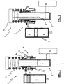
figure 1 is a schematic longitudinal section view of a suspension according to the invention, with the piston in a first position; -
figure 2 is a schematic longitudinal section view of a suspension according to the invention, with the piston in a second position; -
figure 3 is a longitudinal section view of said tank; -
figure 4 is a schematic view of said at least one third chamber. - Referring particularly to such figures, with
numeral 1 is shown a container according to the invention. - Referring to
figure 1 , thesuspension 1 for a wheeled vehicle comprises afluidic damper 2 constrained between awheel 50 and theframe 51 of said vehicle (herein not shown) and provided with a cylinder 3 and apiston 4 sliding within said cylinder 3 and a spring element 5, for example a coil spring, coupleable to saidfluidic damper 2 for the transmission of loads between saidwheel 50 and saidframe 51 when the position of saidpiston 4 with respect to said cylinder 3 changes. Said coil spring 5 is coaxial to saidfluidic damper 2. Furthermore, saidsuspension 1 comprisesmeans 6 for changing the law of transmission of loads of said spring element 5 when the position of saidpiston 4 relative to said cylinder 3 changes. Said means 6 for changing the law of transmission of loads comprise agas spring 7 operatively coupled in series to said spring element 5 and acting for at least part of the stroke of saidpiston 4 relative to said cylinder 3. In detail, still according to the embodiment described herein, saidgas spring 7 comprises afirst chamber 8 containing a gas, particularly air, and is provided with apartition wall 20 which is sliding within saidfirst chamber 8 based on the position of saidpiston 4 relative to said cylinder 3, to change the gas volume and/or pressure inside saidfirst chamber 8. Preferably, said spring element 5 has a high spring modulus, in any case constant, whereas saidair spring 7 operates through a stroke of thepiston 4 lower than the operating stroke of the spring element 5. This allows to operate thesuspension 1 through the first displacement length of thepiston 4 relative to the cylinder 3, and at a higher spring modulus through the remaining displacement length of thepiston 4. - It should be noted that, although the embodiments herein described relate to the
suspension 1, nevertheless an embodiment relating only to themeans 6 for changing the law of transmission of the loads, examined separately from saidsuspension 1, still falls within the protection scope of the present invention. Furthermore, it should be noted that, hereinafter, the described embodiment provides for apartition wall 20 sliding within saidfirst chamber 8, nevertheless an embodiment wherein saidpartition wall 20 is deformable and comprises, for example, a diaphragm, still falls within the protection scope of the present invention. - Further, said
gas spring 7 also comprises as well a second 9 and a third 10 chamber fluidically communicating with each other through aduct 13 and containing an incompressible fluid, for example oil, so that the oil could be transferred from saidsecond chamber 9 to saidthird chamber 10, and vice versa, when the position of saidpiston 4 relative to said cylinder 3 changes. Note that an embodiment wherein thegas spring 7 comprises only saidfirst chamber 8 still falls within the protection scope of the present invention, although not shown. - Basically, the incompressible fluid transferred between said second 9 and said
third chamber 10, and vice versa, never contacts the fluid in thefluidic damper 2 displaced by thepiston 4 during its sliding inside the cylinder 3, therefore saidsecond chamber 9 and saidthird chamber 10 are fluidically independent from thefluidic damper 2. Therefore, ultimately, thegas spring 7 is fluidically independent from saidfluidic damper 2. - More specifically, said
third chamber 10 is provided with afirst portion 11 directly or indirectly coupled to the cylinder and asecond portion 12 constrained sliding movable sealingly with respect to saidfirst portion 11 to transfer the oil between saidsecond chamber 9 and saidthird chamber 10 and vice versa, when the position of saidpiston 4 relative to said cylinder 3 changes. The above mentionedpartition wall 20 is sliding as well, based on the incompressible fluid volume transferred from saidsecond chamber 9 to saidthird camber 10, and vice versa. As shown infigures 1 to 3 , said first 8 and saidsecond chamber 9 are formed inside atank 100 and saidwall 20 is sliding inside saidtank 100 to define saidfirst chamber 8 and saidsecond chamber 9. Moreover, saidfirst portion 11 and saidsecond portion 12 of saidthird chamber 10 are arranged coaxially to saidfluidic damper 2. In the embodiment shown herein, saidthird chamber 10 has a substantially annular shape in which saidfirst portion 11 comprises a firsthollow sleeve 11a having azone 70 constrained by interference to said cylinder 3 of saidfluidic damper 2 and saidsecond portion 12 comprises a secondhollow sleeve 12a shaped to sealingly slide on the outside of said firsthollow sleeve 11. Thus, said spring element 5 has anend 5a abutting against saidsecond portion 12 of saidthird chamber 10. - As shown in
figure 3 , saidgas spring 7 further comprises first means for adjusting the air input/ output to/from saidfirst chamber 8. Particularly, said first adjusting means comprise avalve 30 fluidically connected with saidfirst chamber 8 and a system (herein not shown) for the inflow/ outflow of gas, for example preferably air, from/to said at least one first chamber. This system for the gas inflow/ outflow from/to said chamber, not shown herein, but nevertheless known to the field technician, comprises in a very simplified embodiment, a circuit housing a compressor operated by compressor adjusting elements. Thus, the circuit allows to introduce or extract air into/from saidfirst chamber 8, venting air to the outside, according to the requests of the designer and/or the user. Actually, the control can take place either every time the car set-up changes or dynamically according to the presence of any sensors that automatically change the stiffness of thegas spring 7 based on measurements of the chamber pressure or volume. - Again, said
gas spring 7 comprises second means for adjusting said incompressible fluid input/ output to/from said second 9 andthird chamber 10. Even in this case, said second adjusting means comprise avalve 40 fluidically connected with said connectingduct 13 and a second system for the inflow/ outflow of said incompressible fluid from/to said at least one connecting duct. This system for the inflow/ outflow of incompressible fluid from/to said at least one connectingduct 13, not shown here, is highly well known to the field technician and comprises, in its simplified form, a closed circuit comprising at least one pump ad at least one pair of electro-valves to open and close the circuit based on the designer requirements either during the initial set-up arrangement of the vehicle, or dynamically if the set-up changes on user request. Therefore, this system allows to change the total stiffness of thegas spring 7 as well as the ground clearance of the vehicle. - Finally, even if the one or more embodiments described above relate to said
suspension 1, the invention also relates to the only means 6 for changing the law of transmission of loads for one spring element 5 of asuspension 1 comprising afluidic damper 2 provided with a cylinder 3 and apiston 4 sliding inside said cylinder 3, examined separately from saidsuspension 1 too. Particularly, said spring element 5, preferably a coil spring, is coupleable to saidfluidic damper 2 to transmit loads between said wheel and said frame when the position of said piston 3 relative to saidcylinder 4 changes. The above mentioned means 6 for changing the law of transmission of loads comprise agas spring 7 operatively coupled in series to said spring element 5 and acting a length of the stroke of saidpiston 4 relative to said cylinder 3. Preferably, said spring element 5 of the coil spring type has a very high, anyway constant, spring modulus whereas saidair spring 7 has a lower travel with respect to the spring element. Thus, thesemeans 6 for changing the law of transmission of loads can be coupled in series to anysuspension 1 provided with afluidic damper 2 and one or more spring elements 5. The inclusion of said means for changing the law of transmission of said spring element in known suspensions operating with one or more coil springs of constant modulus, gives the possibility to adapt them in a later time.
Claims (9)
- Suspension (1) for a wheeled vehicle comprising at least one fluidic damper (2) constrained between at least one wheel (50) and the frame (51) of said vehicle and provided with a cylinder (3) and a piston (4) sliding within said cylinder, at least one spring element (5) coupled to said fluidic damper for the transmission of loads between said at least one wheel and said frame when the position of said piston with respect to said cylinder changes, and means (6) for changing the law of transmission of loads of said at least one spring element (5) when the position of said piston relative to said cylinder changes, said means for changing the law of transmission of loads comprising at least one gas spring (7) operatively coupled in series to said at least one spring element (5) and acting for at least part of the stroke of said piston relative to said cylinder, said at least one gas spring being fluidically independent from said at least one fluidic damper, said at least one gas spring (7) comprising at least one first chamber (8) containing a gas, said at least one first chamber being provided with at least one partition wall (20) which is sliding, or deformable, within said at least one first chamber based on the position of said piston relative to said cylinder, to change the gas pressure or volume inside said at least one first chamber, said at least one gas spring (7) comprising as well at least one second (9) and one third chamber (10) fluidically communicating with each other and containing an incompressible fluid, said at least one third chamber (10) being provided with at least one first portion (11) directly or indirectly connected to said cylinder (3), and at least one second portion (12) constrained movable sealingly with respect to said at least one first portion (11) to transfer said incompressible fluid between said at least one second chamber and said at least one third chamber, and vice versa, when the position of said piston relative to said cylinder changes, said at least one partition wall (20) being slidable as well, or deformable, based on the incompressible fluid volume transferred from said at least one second chamber to said at least one third chamber, and vice versa, said at least one second chamber and said at least one third chamber being fluidically independent from said at least one fluidic damper, characterized in that said at least one gas spring comprises second means for adjusting said incompressible fluid input/ output to/ from said at least one second and third chamber, said second adjusting means comprising at least one valve (40) fluidically connected with said connecting duct, or said at least one second chamber or said at least one third chamber, and a second system for the inflow/ outflow of said incompressible fluid from/to said at least one connecting duct, wherein said at least one gas spring comprises first means for adjusting the gas input/ output to/ from said at least one first chamber, said first adjusting means comprising at least one valve (30), fluidically connected with said at least one first chamber, and a system for gas inflow/ outflow from/ to said at least one first chamber.
- Suspension (1) according to claim 1, characterized in that said at least one first and said at least one second chamber are formed inside a tank (100) and said at least one wall (20) is slidable, or deformable, inside said tank to define at least one first chamber and said at least one second chamber.
- Suspension (1) according to claim 2, characterized in that said at least one first portion and said at least one second portion of said at least one third chamber are arranged coaxially to said fluidic damper.
- Suspension (1) according to claim 3, characterized in that said at least one third chamber has a substantially annular shape.
- Suspension (1) according to claim 3 or 4, characterized in that said at least one first portion comprises at least one first hollow sleeve (11a) and said at least one second portion comprises at least one second hollow sleeve (12a) shaped to sealingly slide with respect to said at least one first hollow sleeve (11a).
- Suspension (1) according to one or more of claims 2 to 5, characterized in that said at least one gas spring comprises at least one duct (13) for fluidically connecting said at least one second chamber (9) with said at least one third chamber (10) to transfer said incompressible fluid between said at least one second chamber and said at least one third chamber, and vice versa.
- Suspension (1) according to one or more of the preceding claims, characterized in that said at least one spring element (5) is coaxial to said fluidic damper.
- Suspension (1) according to claim 7, characterized in that said at least one spring element has an end (5a) abutting against said at least one second portion (12) of said at least one third chamber.
- Means (6) for changing the law of transmission of loads for at least one spring element (5) of a suspension comprising at least one fluidic damper (2) provided with a cylinder (3) and a piston (4) which is sliding inside said cylinder, wherein said at least one spring element (5) is coupled to said fluidic damper to transmit loads between said at least one wheel and said frame when the position of said piston with respect to said cylinder changes, said means for changing the law of transmission of loads comprising at least one gas spring (7) operatively coupled in series to said at least one spring element (5) and acting for at least part of said piston stroke relative to said cylinder, said at least one gas spring being fluidically independent from said at least one fluidic damper, said at least one gas spring (7) comprising at least one first chamber (8) containing a gas, said at least one first chamber being provided with at least one partition wall (20) which is sliding, or deformable, within said at least one first chamber based on the position of said piston relative to said cylinder, to change the gas, or pressure, volume inside said at least one first chamber, said at least one gas spring (7) comprising as well at least one second (9) and one third chamber (10) fluidically communicating with each other and containing an incompressible fluid, said at least one third chamber (10) being provided with at least one first portion (11) directly or indirectly connected to said cylinder (3), and at least one second portion (12) constrained movable sealingly with respect to said at least one first portion (11) to transfer said incompressible fluid between said at least one second chamber and said at least one third chamber, and vice versa, when the position of said piston relative to said cylinder changes, said at least one partition wall (20) being slidable as well, or deformable, based on the incompressible fluid volume transferred from said at least one second chamber to said at least one third chamber, and vice versa, said at least one second chamber and said at least one third chamber being fluidically independent from said at least one fluidic damper, characterized in that said at least one gas spring comprises second means for adjusting said incompressible fluid input/ output to/ from said at least one second and third chamber, said second adjusting means comprising at least one valve (40) fluidically connected with said connecting duct, or said at least one second chamber or said at least one third chamber, and a second system for the inflow/ outflow of said incompressible fluid from/to said at least one connecting duct, wherein said at least one gas spring comprises first means for adjusting the gas input/ output to/ from said at least one first chamber, and wherein said first adjusting means comprise at least one valve (30), fluidically connected with said at least one first chamber, and a system for gas inflow/ outflow from/to said at least one first chamber.
Applications Claiming Priority (2)
| Application Number | Priority Date | Filing Date | Title |
|---|---|---|---|
| IT001683A ITMI20121683A1 (en) | 2012-10-08 | 2012-10-08 | SUSPENSION FOR VEHICLE WITH WHEELS |
| PCT/IB2013/002216 WO2014057334A1 (en) | 2012-10-08 | 2013-10-07 | Suspension for a wheeled vehicle |
Publications (2)
| Publication Number | Publication Date |
|---|---|
| EP2903840A1 EP2903840A1 (en) | 2015-08-12 |
| EP2903840B1 true EP2903840B1 (en) | 2018-12-05 |
Family
ID=47388535
Family Applications (1)
| Application Number | Title | Priority Date | Filing Date |
|---|---|---|---|
| EP13805508.2A Active EP2903840B1 (en) | 2012-10-08 | 2013-10-07 | Suspension for a wheeled vehicle |
Country Status (4)
| Country | Link |
|---|---|
| EP (1) | EP2903840B1 (en) |
| ES (1) | ES2714524T3 (en) |
| IT (1) | ITMI20121683A1 (en) |
| WO (1) | WO2014057334A1 (en) |
Cited By (1)
| Publication number | Priority date | Publication date | Assignee | Title |
|---|---|---|---|---|
| IT202100008516A1 (en) | 2021-04-06 | 2022-10-06 | Umbria Kinetics Srl | SHOCK ABSORBER FOR WHEEL VEHICLES. |
Families Citing this family (5)
| Publication number | Priority date | Publication date | Assignee | Title |
|---|---|---|---|---|
| US9834058B2 (en) | 2014-12-04 | 2017-12-05 | Sistemi Sospensioni S.P.A. | Linear actuator for adjusting the vertical position of a spring of a damper and spring unit for a vehicle suspension and damper and spring unit for a vehicle suspension comprising such an actuator |
| DE102016213429A1 (en) * | 2016-07-22 | 2018-01-25 | Bayerische Motoren Werke Aktiengesellschaft | Spring and damping arrangement for a motorcycle |
| DE102017201642A1 (en) * | 2017-02-02 | 2018-08-02 | Zf Friedrichshafen Ag | Spring strut with variable spring rate |
| DE102019119419B4 (en) * | 2019-07-17 | 2023-01-12 | Ktm Ag | Pneumatically actuable adjustment device for loading a spring device of a spring damper device having a tubular body |
| IT202100004217A1 (en) * | 2021-02-23 | 2022-08-23 | Yamaha Motor Co Ltd | HEIGHT ADJUSTABLE SADDLE TYPE VEHICLE AND RELATED CONTROL METHOD |
Citations (5)
| Publication number | Priority date | Publication date | Assignee | Title |
|---|---|---|---|---|
| JPS60136635A (en) * | 1983-12-22 | 1985-07-20 | Showa Mfg Co Ltd | Variable spring constant damper |
| JPS60192138A (en) * | 1984-03-14 | 1985-09-30 | Showa Mfg Co Ltd | Variable spring constant damper |
| JPH0667942U (en) * | 1993-02-26 | 1994-09-22 | カヤバ工業株式会社 | Vehicle height adjustment device |
| JPH10299811A (en) * | 1997-04-25 | 1998-11-13 | Showa:Kk | Vehicle height adjusting device and method of using the same |
| DE102005008814A1 (en) * | 2005-02-24 | 2006-09-07 | H & R Spezialfedern Gmbh & Co. Kg | Hydraulic height adjusting device for e.g. motor vehicle chassis, has piston mechanism circularly surrounding exterior of support tube, and chamber formed by tube exterior, interiors of cylindrical arrangement and front side of mechanism |
Family Cites Families (10)
| Publication number | Priority date | Publication date | Assignee | Title |
|---|---|---|---|---|
| DE3174727D1 (en) * | 1980-11-25 | 1986-07-03 | Bayerische Motoren Werke Ag | Suspension system for vehicles |
| JPS5826613A (en) * | 1981-08-11 | 1983-02-17 | Showa Mfg Co Ltd | Car level-control oleo fork |
| JPS59137206A (en) * | 1983-01-24 | 1984-08-07 | Nissan Motor Co Ltd | Suspension device |
| JPS59165287U (en) * | 1983-04-22 | 1984-11-06 | カヤバ工業株式会社 | suspension system |
| JP2797133B2 (en) * | 1990-03-14 | 1998-09-17 | 日野自動車工業株式会社 | Hydropneumatic suspension device |
| DE10123491A1 (en) * | 2001-05-15 | 2002-11-21 | Porsche Ag | Adjustable shock absorber for a motor vehicle |
| DE102004032083B4 (en) * | 2004-07-02 | 2007-05-31 | Audi Ag | Spring and damping device for wheel suspensions |
| JP2006131066A (en) * | 2004-11-05 | 2006-05-25 | Nissan Motor Co Ltd | Suspension device |
| JP2007030660A (en) * | 2005-07-26 | 2007-02-08 | Nissan Motor Co Ltd | Vehicle height adjustment device |
| DE102009045051B4 (en) * | 2009-09-28 | 2011-09-01 | Zf Friedrichshafen Ag | Adjustable strut |
-
2012
- 2012-10-08 IT IT001683A patent/ITMI20121683A1/en unknown
-
2013
- 2013-10-07 ES ES13805508T patent/ES2714524T3/en active Active
- 2013-10-07 EP EP13805508.2A patent/EP2903840B1/en active Active
- 2013-10-07 WO PCT/IB2013/002216 patent/WO2014057334A1/en not_active Ceased
Patent Citations (5)
| Publication number | Priority date | Publication date | Assignee | Title |
|---|---|---|---|---|
| JPS60136635A (en) * | 1983-12-22 | 1985-07-20 | Showa Mfg Co Ltd | Variable spring constant damper |
| JPS60192138A (en) * | 1984-03-14 | 1985-09-30 | Showa Mfg Co Ltd | Variable spring constant damper |
| JPH0667942U (en) * | 1993-02-26 | 1994-09-22 | カヤバ工業株式会社 | Vehicle height adjustment device |
| JPH10299811A (en) * | 1997-04-25 | 1998-11-13 | Showa:Kk | Vehicle height adjusting device and method of using the same |
| DE102005008814A1 (en) * | 2005-02-24 | 2006-09-07 | H & R Spezialfedern Gmbh & Co. Kg | Hydraulic height adjusting device for e.g. motor vehicle chassis, has piston mechanism circularly surrounding exterior of support tube, and chamber formed by tube exterior, interiors of cylindrical arrangement and front side of mechanism |
Cited By (2)
| Publication number | Priority date | Publication date | Assignee | Title |
|---|---|---|---|---|
| IT202100008516A1 (en) | 2021-04-06 | 2022-10-06 | Umbria Kinetics Srl | SHOCK ABSORBER FOR WHEEL VEHICLES. |
| EP4070974A1 (en) | 2021-04-06 | 2022-10-12 | Umbria Kinetics SRL | Shock absorber for wheeled vehicles |
Also Published As
| Publication number | Publication date |
|---|---|
| ES2714524T3 (en) | 2019-05-28 |
| ITMI20121683A1 (en) | 2014-04-09 |
| EP2903840A1 (en) | 2015-08-12 |
| WO2014057334A1 (en) | 2014-04-17 |
Similar Documents
| Publication | Publication Date | Title |
|---|---|---|
| EP2903840B1 (en) | Suspension for a wheeled vehicle | |
| US8210330B2 (en) | Electronically controlled frequency dependent damping | |
| JP5519502B2 (en) | shock absorber | |
| US5924528A (en) | Load depending damping assembly | |
| US4607861A (en) | Hydraulic stabilizing system for vehicle suspension | |
| US10414232B2 (en) | Suspension for wheeled vehicle | |
| CN103802626B (en) | Vehicle suspension system | |
| CN106090111B (en) | A kind of adaptive damping hydraulic vibration damper used for vehicle with height adjusting system | |
| CN110869224B (en) | Spring damper system with variable spring stiffness and spring constant control method | |
| JP2012517925A (en) | Active suspension system and fluid pressure driven ram for use in the active suspension system | |
| EP1231403B1 (en) | Frequency dependent damper | |
| US10035400B2 (en) | Vehicle suspension system | |
| Cao et al. | Pitch plane analysis of a twin-gas-chamber strut suspension | |
| CN106704442B (en) | Oil and gas spring | |
| WO2018092111A1 (en) | Vehicle wheel suspension provided with active adjustment system for adjusting in a controlled manner the overall stiffness of the suspension | |
| CN103895468A (en) | Vehicle suspension system and motor vehicle | |
| CN207673772U (en) | A kind of pneumatic cylinder | |
| EP2225115B1 (en) | Suspension system, vehicle comprising such a suspension system and a method for controlling a suspension system | |
| EP4070974B1 (en) | Shock absorber for wheeled vehicles | |
| CN103982584B (en) | Sliding piston formula amplitude is correlated with orifice valve | |
| US9193242B2 (en) | Air shock absorber with smart suspension system with height adjustment without losing comfort and safety | |
| US8087646B2 (en) | Hydropneumatic suspension with load-dependent damping control | |
| CN107989947B (en) | A multi-piston damping adjustable shock absorber mechanism | |
| EP2935931B1 (en) | Self-adjusting, self-damping air spring system and method of damping oscillation | |
| JP2025505098A (en) | Dual Volume Air Spring |
Legal Events
| Date | Code | Title | Description |
|---|---|---|---|
| PUAI | Public reference made under article 153(3) epc to a published international application that has entered the european phase |
Free format text: ORIGINAL CODE: 0009012 |
|
| 17P | Request for examination filed |
Effective date: 20150507 |
|
| AK | Designated contracting states |
Kind code of ref document: A1 Designated state(s): AL AT BE BG CH CY CZ DE DK EE ES FI FR GB GR HR HU IE IS IT LI LT LU LV MC MK MT NL NO PL PT RO RS SE SI SK SM TR |
|
| AX | Request for extension of the european patent |
Extension state: BA ME |
|
| DAX | Request for extension of the european patent (deleted) | ||
| 17Q | First examination report despatched |
Effective date: 20160622 |
|
| STAA | Information on the status of an ep patent application or granted ep patent |
Free format text: STATUS: EXAMINATION IS IN PROGRESS |
|
| GRAP | Despatch of communication of intention to grant a patent |
Free format text: ORIGINAL CODE: EPIDOSNIGR1 |
|
| STAA | Information on the status of an ep patent application or granted ep patent |
Free format text: STATUS: GRANT OF PATENT IS INTENDED |
|
| INTG | Intention to grant announced |
Effective date: 20180608 |
|
| GRAS | Grant fee paid |
Free format text: ORIGINAL CODE: EPIDOSNIGR3 |
|
| GRAA | (expected) grant |
Free format text: ORIGINAL CODE: 0009210 |
|
| STAA | Information on the status of an ep patent application or granted ep patent |
Free format text: STATUS: THE PATENT HAS BEEN GRANTED |
|
| AK | Designated contracting states |
Kind code of ref document: B1 Designated state(s): AL AT BE BG CH CY CZ DE DK EE ES FI FR GB GR HR HU IE IS IT LI LT LU LV MC MK MT NL NO PL PT RO RS SE SI SK SM TR |
|
| REG | Reference to a national code |
Ref country code: GB Ref legal event code: FG4D |
|
| REG | Reference to a national code |
Ref country code: CH Ref legal event code: EP |
|
| REG | Reference to a national code |
Ref country code: AT Ref legal event code: REF Ref document number: 1072566 Country of ref document: AT Kind code of ref document: T Effective date: 20181215 |
|
| REG | Reference to a national code |
Ref country code: IE Ref legal event code: FG4D |
|
| REG | Reference to a national code |
Ref country code: DE Ref legal event code: R096 Ref document number: 602013047884 Country of ref document: DE |
|
| REG | Reference to a national code |
Ref country code: CH Ref legal event code: NV Representative=s name: FABIANO, FRANKE AND MGT SAGL, CH |
|
| REG | Reference to a national code |
Ref country code: SE Ref legal event code: TRGR |
|
| REG | Reference to a national code |
Ref country code: NL Ref legal event code: FP |
|
| REG | Reference to a national code |
Ref country code: LT Ref legal event code: MG4D |
|
| PG25 | Lapsed in a contracting state [announced via postgrant information from national office to epo] |
Ref country code: HR Free format text: LAPSE BECAUSE OF FAILURE TO SUBMIT A TRANSLATION OF THE DESCRIPTION OR TO PAY THE FEE WITHIN THE PRESCRIBED TIME-LIMIT Effective date: 20181205 Ref country code: LT Free format text: LAPSE BECAUSE OF FAILURE TO SUBMIT A TRANSLATION OF THE DESCRIPTION OR TO PAY THE FEE WITHIN THE PRESCRIBED TIME-LIMIT Effective date: 20181205 Ref country code: LV Free format text: LAPSE BECAUSE OF FAILURE TO SUBMIT A TRANSLATION OF THE DESCRIPTION OR TO PAY THE FEE WITHIN THE PRESCRIBED TIME-LIMIT Effective date: 20181205 Ref country code: NO Free format text: LAPSE BECAUSE OF FAILURE TO SUBMIT A TRANSLATION OF THE DESCRIPTION OR TO PAY THE FEE WITHIN THE PRESCRIBED TIME-LIMIT Effective date: 20190305 Ref country code: FI Free format text: LAPSE BECAUSE OF FAILURE TO SUBMIT A TRANSLATION OF THE DESCRIPTION OR TO PAY THE FEE WITHIN THE PRESCRIBED TIME-LIMIT Effective date: 20181205 Ref country code: BG Free format text: LAPSE BECAUSE OF FAILURE TO SUBMIT A TRANSLATION OF THE DESCRIPTION OR TO PAY THE FEE WITHIN THE PRESCRIBED TIME-LIMIT Effective date: 20190305 |
|
| REG | Reference to a national code |
Ref country code: CH Ref legal event code: PCAR Free format text: NEW ADDRESS: PIAZZETTA SAN CARLO 2, 6900 LUGANO (CH) |
|
| REG | Reference to a national code |
Ref country code: ES Ref legal event code: FG2A Ref document number: 2714524 Country of ref document: ES Kind code of ref document: T3 Effective date: 20190528 |
|
| PG25 | Lapsed in a contracting state [announced via postgrant information from national office to epo] |
Ref country code: GR Free format text: LAPSE BECAUSE OF FAILURE TO SUBMIT A TRANSLATION OF THE DESCRIPTION OR TO PAY THE FEE WITHIN THE PRESCRIBED TIME-LIMIT Effective date: 20190306 Ref country code: AL Free format text: LAPSE BECAUSE OF FAILURE TO SUBMIT A TRANSLATION OF THE DESCRIPTION OR TO PAY THE FEE WITHIN THE PRESCRIBED TIME-LIMIT Effective date: 20181205 Ref country code: RS Free format text: LAPSE BECAUSE OF FAILURE TO SUBMIT A TRANSLATION OF THE DESCRIPTION OR TO PAY THE FEE WITHIN THE PRESCRIBED TIME-LIMIT Effective date: 20181205 |
|
| PG25 | Lapsed in a contracting state [announced via postgrant information from national office to epo] |
Ref country code: PL Free format text: LAPSE BECAUSE OF FAILURE TO SUBMIT A TRANSLATION OF THE DESCRIPTION OR TO PAY THE FEE WITHIN THE PRESCRIBED TIME-LIMIT Effective date: 20181205 Ref country code: PT Free format text: LAPSE BECAUSE OF FAILURE TO SUBMIT A TRANSLATION OF THE DESCRIPTION OR TO PAY THE FEE WITHIN THE PRESCRIBED TIME-LIMIT Effective date: 20190405 |
|
| PG25 | Lapsed in a contracting state [announced via postgrant information from national office to epo] |
Ref country code: RO Free format text: LAPSE BECAUSE OF FAILURE TO SUBMIT A TRANSLATION OF THE DESCRIPTION OR TO PAY THE FEE WITHIN THE PRESCRIBED TIME-LIMIT Effective date: 20181205 Ref country code: SM Free format text: LAPSE BECAUSE OF FAILURE TO SUBMIT A TRANSLATION OF THE DESCRIPTION OR TO PAY THE FEE WITHIN THE PRESCRIBED TIME-LIMIT Effective date: 20181205 Ref country code: EE Free format text: LAPSE BECAUSE OF FAILURE TO SUBMIT A TRANSLATION OF THE DESCRIPTION OR TO PAY THE FEE WITHIN THE PRESCRIBED TIME-LIMIT Effective date: 20181205 Ref country code: IS Free format text: LAPSE BECAUSE OF FAILURE TO SUBMIT A TRANSLATION OF THE DESCRIPTION OR TO PAY THE FEE WITHIN THE PRESCRIBED TIME-LIMIT Effective date: 20190405 Ref country code: SK Free format text: LAPSE BECAUSE OF FAILURE TO SUBMIT A TRANSLATION OF THE DESCRIPTION OR TO PAY THE FEE WITHIN THE PRESCRIBED TIME-LIMIT Effective date: 20181205 |
|
| REG | Reference to a national code |
Ref country code: DE Ref legal event code: R097 Ref document number: 602013047884 Country of ref document: DE |
|
| PLBE | No opposition filed within time limit |
Free format text: ORIGINAL CODE: 0009261 |
|
| STAA | Information on the status of an ep patent application or granted ep patent |
Free format text: STATUS: NO OPPOSITION FILED WITHIN TIME LIMIT |
|
| PG25 | Lapsed in a contracting state [announced via postgrant information from national office to epo] |
Ref country code: DK Free format text: LAPSE BECAUSE OF FAILURE TO SUBMIT A TRANSLATION OF THE DESCRIPTION OR TO PAY THE FEE WITHIN THE PRESCRIBED TIME-LIMIT Effective date: 20181205 Ref country code: SI Free format text: LAPSE BECAUSE OF FAILURE TO SUBMIT A TRANSLATION OF THE DESCRIPTION OR TO PAY THE FEE WITHIN THE PRESCRIBED TIME-LIMIT Effective date: 20181205 |
|
| 26N | No opposition filed |
Effective date: 20190906 |
|
| PG25 | Lapsed in a contracting state [announced via postgrant information from national office to epo] |
Ref country code: TR Free format text: LAPSE BECAUSE OF FAILURE TO SUBMIT A TRANSLATION OF THE DESCRIPTION OR TO PAY THE FEE WITHIN THE PRESCRIBED TIME-LIMIT Effective date: 20181205 |
|
| PG25 | Lapsed in a contracting state [announced via postgrant information from national office to epo] |
Ref country code: MC Free format text: LAPSE BECAUSE OF FAILURE TO SUBMIT A TRANSLATION OF THE DESCRIPTION OR TO PAY THE FEE WITHIN THE PRESCRIBED TIME-LIMIT Effective date: 20181205 |
|
| PG25 | Lapsed in a contracting state [announced via postgrant information from national office to epo] |
Ref country code: LU Free format text: LAPSE BECAUSE OF NON-PAYMENT OF DUE FEES Effective date: 20191007 |
|
| REG | Reference to a national code |
Ref country code: BE Ref legal event code: MM Effective date: 20191031 |
|
| PG25 | Lapsed in a contracting state [announced via postgrant information from national office to epo] |
Ref country code: BE Free format text: LAPSE BECAUSE OF NON-PAYMENT OF DUE FEES Effective date: 20191031 |
|
| REG | Reference to a national code |
Ref country code: AT Ref legal event code: UEP Ref document number: 1072566 Country of ref document: AT Kind code of ref document: T Effective date: 20181205 |
|
| PG25 | Lapsed in a contracting state [announced via postgrant information from national office to epo] |
Ref country code: CY Free format text: LAPSE BECAUSE OF FAILURE TO SUBMIT A TRANSLATION OF THE DESCRIPTION OR TO PAY THE FEE WITHIN THE PRESCRIBED TIME-LIMIT Effective date: 20181205 |
|
| PG25 | Lapsed in a contracting state [announced via postgrant information from national office to epo] |
Ref country code: HU Free format text: LAPSE BECAUSE OF FAILURE TO SUBMIT A TRANSLATION OF THE DESCRIPTION OR TO PAY THE FEE WITHIN THE PRESCRIBED TIME-LIMIT; INVALID AB INITIO Effective date: 20131007 |
|
| PG25 | Lapsed in a contracting state [announced via postgrant information from national office to epo] |
Ref country code: MK Free format text: LAPSE BECAUSE OF FAILURE TO SUBMIT A TRANSLATION OF THE DESCRIPTION OR TO PAY THE FEE WITHIN THE PRESCRIBED TIME-LIMIT Effective date: 20181205 |
|
| PGFP | Annual fee paid to national office [announced via postgrant information from national office to epo] |
Ref country code: IE Payment date: 20230928 Year of fee payment: 11 |
|
| PGFP | Annual fee paid to national office [announced via postgrant information from national office to epo] |
Ref country code: NL Payment date: 20231025 Year of fee payment: 11 |
|
| PGFP | Annual fee paid to national office [announced via postgrant information from national office to epo] |
Ref country code: MT Payment date: 20230928 Year of fee payment: 11 |
|
| PGFP | Annual fee paid to national office [announced via postgrant information from national office to epo] |
Ref country code: CZ Payment date: 20231006 Year of fee payment: 11 |
|
| PG25 | Lapsed in a contracting state [announced via postgrant information from national office to epo] |
Ref country code: CZ Free format text: LAPSE BECAUSE OF NON-PAYMENT OF DUE FEES Effective date: 20241007 |
|
| REG | Reference to a national code |
Ref country code: NL Ref legal event code: MM Effective date: 20241101 |
|
| PG25 | Lapsed in a contracting state [announced via postgrant information from national office to epo] |
Ref country code: NL Free format text: LAPSE BECAUSE OF NON-PAYMENT OF DUE FEES Effective date: 20241101 |
|
| PG25 | Lapsed in a contracting state [announced via postgrant information from national office to epo] |
Ref country code: IE Free format text: LAPSE BECAUSE OF NON-PAYMENT OF DUE FEES Effective date: 20241007 |
|
| REG | Reference to a national code |
Ref country code: CH Ref legal event code: U11 Free format text: ST27 STATUS EVENT CODE: U-0-0-U10-U11 (AS PROVIDED BY THE NATIONAL OFFICE) Effective date: 20251101 |
|
| PGFP | Annual fee paid to national office [announced via postgrant information from national office to epo] |
Ref country code: GB Payment date: 20251021 Year of fee payment: 13 |
|
| PGFP | Annual fee paid to national office [announced via postgrant information from national office to epo] |
Ref country code: AT Payment date: 20251028 Year of fee payment: 13 |
|
| PGFP | Annual fee paid to national office [announced via postgrant information from national office to epo] |
Ref country code: IT Payment date: 20251022 Year of fee payment: 13 |
|
| PGFP | Annual fee paid to national office [announced via postgrant information from national office to epo] |
Ref country code: FR Payment date: 20251022 Year of fee payment: 13 |
|
| PGFP | Annual fee paid to national office [announced via postgrant information from national office to epo] |
Ref country code: SE Payment date: 20251022 Year of fee payment: 13 Ref country code: CH Payment date: 20251101 Year of fee payment: 13 |
|
| PGFP | Annual fee paid to national office [announced via postgrant information from national office to epo] |
Ref country code: ES Payment date: 20251104 Year of fee payment: 13 |
|
| PGFP | Annual fee paid to national office [announced via postgrant information from national office to epo] |
Ref country code: DE Payment date: 20251222 Year of fee payment: 13 |