EP2903301B1 - Improving at least one of intelligibility or loudness of an audio program - Google Patents
Improving at least one of intelligibility or loudness of an audio program Download PDFInfo
- Publication number
- EP2903301B1 EP2903301B1 EP15151272.0A EP15151272A EP2903301B1 EP 2903301 B1 EP2903301 B1 EP 2903301B1 EP 15151272 A EP15151272 A EP 15151272A EP 2903301 B1 EP2903301 B1 EP 2903301B1
- Authority
- EP
- European Patent Office
- Prior art keywords
- signal
- signals
- upmix
- audio program
- surround
- Prior art date
- Legal status (The legal status is an assumption and is not a legal conclusion. Google has not performed a legal analysis and makes no representation as to the accuracy of the status listed.)
- Active
Links
Images




Classifications
-
- H—ELECTRICITY
- H04—ELECTRIC COMMUNICATION TECHNIQUE
- H04S—STEREOPHONIC SYSTEMS
- H04S3/00—Systems employing more than two channels, e.g. quadraphonic
- H04S3/006—Systems employing more than two channels, e.g. quadraphonic in which a plurality of audio signals are transformed in a combination of audio signals and modulated signals, e.g. CD-4 systems
-
- H—ELECTRICITY
- H04—ELECTRIC COMMUNICATION TECHNIQUE
- H04S—STEREOPHONIC SYSTEMS
- H04S3/00—Systems employing more than two channels, e.g. quadraphonic
- H04S3/02—Systems employing more than two channels, e.g. quadraphonic of the matrix type, i.e. in which input signals are combined algebraically, e.g. after having been phase shifted with respect to each other
-
- H—ELECTRICITY
- H04—ELECTRIC COMMUNICATION TECHNIQUE
- H04S—STEREOPHONIC SYSTEMS
- H04S2400/00—Details of stereophonic systems covered by H04S but not provided for in its groups
- H04S2400/01—Multi-channel, i.e. more than two input channels, sound reproduction with two speakers wherein the multi-channel information is substantially preserved
-
- H—ELECTRICITY
- H04—ELECTRIC COMMUNICATION TECHNIQUE
- H04S—STEREOPHONIC SYSTEMS
- H04S2400/00—Details of stereophonic systems covered by H04S but not provided for in its groups
- H04S2400/03—Aspects of down-mixing multi-channel audio to configurations with lower numbers of playback channels, e.g. 7.1 -> 5.1
-
- H—ELECTRICITY
- H04—ELECTRIC COMMUNICATION TECHNIQUE
- H04S—STEREOPHONIC SYSTEMS
- H04S2400/00—Details of stereophonic systems covered by H04S but not provided for in its groups
- H04S2400/13—Aspects of volume control, not necessarily automatic, in stereophonic sound systems
Definitions
- Programs such as those intended for television broadcast are, in many cases, intentionally produced with variable loudness and wide dynamic range to convey emotion or a level of excitement in a given scene.
- a movie may include a scene with the subtle chirping of a cricket and another scene with the blasting sound of a shooting cannon.
- Interstitial material such as commercial advertisements, on the other hand, is very often intended to convey a coherent message, and is, thus, often produced at a constant loudness, narrow dynamic range, or both.
- Annoying loudness disturbances commonly occur at the point of transition between the programming and the interstitial material. Thus the problem is commonly known as the "loud commercial problem.” Loudness annoyances, however, are not limited to the programming/interstitial material transition, but are pervasive within the programming and the interstitial material themselves.
- Another conventional technique measures loudness by measuring whatever component of the audio is the loudest for the longest period of time.
- This technique may provide measurements that deviate from the intent of the programming or from human perception of loudness. This may be particularly true for programming that has wide dynamic range. For example, this technique may erroneously judge the loudness of a scene which contains the roaring sound of a jet flying overhead as too loud. This measurement may result in processing or adjustment of the audio program that, for example, may lower speech components of the audio to unintelligible levels.
- US 2005/074127 A1 discloses an arrangement for processing a multi-channel audio signal having at least three original channels, in which a first downmix channel and a second downmix channel are provided, which are derived from the original channels.
- channel side information is calculated such that a downmix channel or a combined downmix channel including the first and second downmix channels, when weighted using the channel side information, results in an approximation of the selected original channel.
- the channel side information and the first and second downmix channels form output data to be transmitted to a decoder, which, in case of a low level decoder only decodes the first and second downmix channels or, in case of a high level decoder provides a full multi-channel audio signal based on the downmix channels and the channel side information.
- WO 2011/069205 A1 discloses a matrix decoder for use in a surround sound system, wherein at least four audio input signals representing an original sound field are encoded into two channel signals and said encoded signals are decoded into at least four audio output signals corresponding to the four audio input signals and have an amplitude ratio and a phase relationship.
- the decoder includes means for: compensating the said encoded signals for variations in perceived loudness relative to frequency associated with the encoded two channel signals due to non-linearity in human hearing response at least at some frequencies; producing steering signals in response to the phase relationship of the said compensated signals; and decoding said encoded signals to produce audio output signals corresponding to audio input signals by varying at least the amplitude ratio of said encoded signals contained in each of the output signals in response to said steering signals.
- the present disclosure describes novel techniques for improving intelligibility and loudness measurement accuracy of audio programs.
- the present disclosure describes systems and methods for better isolating sounds that humans perceive in an audio program as anchors, which are components of the audio that humans perceive as indicating direction of, for example, action displayed in a TV or movie screen.
- Isolating sounds that humans perceive as anchors enables focused measurement of loudness and intelligibility of the program, which, in turn, allows for the processing of the program based on the anchor-based measurements to improve loudness and/or intelligibility.
- the present disclosure also describes systems and methods whereby frequency and level processing is applied to certain components of front and rear (a.k.a. surround) audio channels to selectively enhance or diminish certain characteristics of the audio signals thus resulting in improved measurement accuracy and intelligibility.
- Separation of front channel and surround (a.k.a. rear) channel audio allows specific processing to be applied to each as required. Examples of processing include frequency and level equalization, often differing in type and style between the front and rear channels, but with the shared goal of preventing one component from overpowering another more important component.
- the techniques disclosed here may find particular application in the fields of broadcast and consumer audio. These techniques may be applied to stereo audio or multichannel audio of more than two channels, including but not limited to common formats such as 5.1 or 7.1 channels. These techniques may be also be applied to systems which use channel based and/or object based audio to convey additional dimensions and reality. Examples of channel and object based audio can be found in the developing MPEG-H standard, or in the recently described Dolby AC-4 system.
- Figures 1A and 1B illustrate high-level block diagrams of an exemplary system 100 for improving at least one of intelligibility or loudness of an audio program.
- the system 100 includes an input 101 that includes a set of terminals including left front Lf, right front Rf, center front Cf, low frequency effects LFE, left surround Ls, and right surround Rs corresponding to a 5.1 channel format.
- the system 100 also includes an output 102 that includes a set of terminals including left front Lf', right front Rf', center front Cf', low frequency effects LFE, left surround Ls', and right surround Rs' corresponding to a 5.1 channel format.
- the input 101 and the output 102 each includes six terminals corresponding to a 5.1 channel format
- the input 101 and the output 102 may include more or less than six terminals corresponding to formats other than a 5.1 channel format (e.g., 2-channel stereo, 3.1, 7.1, etc.)
- the input 101 receives six signals Lf, Rf, Cf, LFE, Ls, and Rs.
- the input 101 receives two signals L and R.
- the system 100 may include a detector 123 that detects whether at least one of the Cf, Ls, or Rs signals is present among signals of the audio program received by the input 101. That is, the detector 123 determines whether the audio program received by the input 101 is in a multichannel format (e.g., 3.1, 5.1, 7.1, etc.) or in a two channel (e.g., stereo) format. As described in more detail below, the system 100 performs differently depending on whether the audio program received by the input 101 is in a multichannel format or in a stereo format.
- a multichannel format e.g., 3.1, 5.1, 7.1, etc.
- a two channel e.g., stereo
- the present disclosure first describes the system 100 in the context of Figure 1A (i.e., the detector 123 has determined that the audio program received at the input 101 is in a 5.1 multichannel format.)
- the system 100 includes a matrix encoder 105 that receives the Lf, Cf, and Rf signals and encodes (i.e., combines or downmixes) the signals to obtain left downmix Ld and right downmix Rd signals.
- the encoder 105 may be one of many encoders or downmixers known in the art.
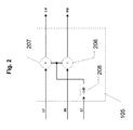
- Figure 2 illustrates a block diagram of an exemplary encoder 105.
- the encoder 105 includes a gain adjust 206 and two summers 207 and 208.
- the gain adjust 206 adjusts the gain of the Cf signal (e.g., by -3dB).
- the summer 207 sums Lf to the gain adjusted Cf signal to obtain Ld.
- the summer 208 sums Rf to the gain adjusted Cf signal to obtain Rd.
- the encoder 105 may be one of many encoders or downmixers known in the art other than the one illustrated in Figure 2 .
- the system 100 includes a matrix decoder 110 that receives the Ld and Rd signals and decodes (e.g., separates or upmixes) the signals to obtain left upmix Lu, right upmix Ru, center upmix Cu, and surround upmix Su.
- the decoder 110 may be one of many decoders or upmixers known in the art an. An example of a decoder that may serve as the decoder 110 is described in U.S. Pat. No. 5,046,098 to Mandell .
- the system 100 includes a matrix decoder that, instead of the surround Su signal, outputs left/surround upmix and right/surround upmix signals.
- the system 100 includes a matrix decoder that does not output a surround upmix Su signal, but only Lu, Ru and Cu.
- the system 100 includes a matrix decoder that center upmix Cu only.
- Multichannel audio of more than two channels presents another challenge in the increasing use of so-called dialog panning where dialog may be present, in addition to the center front Cf channel, in the left front Lf and or right front Rf channels.
- This may require additional techniques to combine the Lf, Rf, and Cf channels prior to further decomposition and may result in the front dominant signals, including speech if present, to be directed primarily to one channel.
- the above-described first downmix then upmix technique tends to direct any audio that is common between left front Lf and center front Cf and any audio that is common between right front Rf and center front Cf into just the center upmix Cu signal.
- the resulting Cu signal includes the vast majority of the anchor elements even for programs in which the original left front Lf and/or right front Rf may also contain anchor elements (e.g., left to right/right to left dialog panning).
- the system 100 may also include the processor 115 that may process the Cu signal to filter out information above and below certain frequencies that are not part of those frequencies normally found in dialog or considered anchors.
- the processor 115 may alternatively or in addition process the Cu signal to enhance speech formants and increase the peak to trough ratio both of which can improve intelligibility.
- the Cu signal (or the processed Cu signal) may be provided via the output 102 for use by processes that may benefit from better anchor isolation.
- the Cu signal (or the processed Cu signal) may also be used to process at least one of the signals of the audio program based on the Cu signal to improve intelligibility or loudness of the audio program.
- the Cu signal may be added to the Cf signal (not shown) to improve intelligibility of the audio program.
- the system 100 may also include or be connected to a meter 113.
- the meter 113 may be compliant with a loudness measurement standard (e.g., EBU R128, ITU-R BS.1770, ATSC A/85, etc.) and the Cu signal (or the processed Cu signal) may be available as an input to the meter 113 so that loudness of the audio program may be measured very precisely.
- the output of the meter 113 may be used by processes that may benefit from better loudness measurement.
- the output of the meter 113 may also be used to process at least one of the signals of the audio program based on the Cu signal to improve intelligibility or loudness of the audio program.
- detector 123 determines signal presence above threshold in the center front Cf, left surround Ls, or right surround Rs channels. If the detector 123 determines signal presence above threshold in the center front Cf, left surround Ls, or right surround Rs channels, the detector 123 may transmit a signal 124 to the switches 125 to allow left front Lf and right front Rf input audio to pass directly from input 101 to the output 102.
- the center front signal Cf often contains most of the dialog present in a program.
- the system 100 may also include a processor 122 that processes the Cf signal.
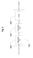
- Figure 3 illustrates a block diagram of an example processor 122 that includes an adjustable equalizer 302, an adjustable gain 303 and a limiter 304.
- the processor 122 therefore enables variable equalization, variable gain, and limiting to be applied to the center channel Cf.
- the adjustable equalizer (EQ) 302 such as a parametric equalizer may be used to modify the frequency response of the Cf signal.
- the variable gain stage 303 may apply positive or negative gain as desired.
- the limiter 304 such as, for example, a peak limiter may prevent audio from exceeding a set threshold before being output as Cf'.
- one or more of the adjustable equalizer 302, the adjustable gain 303 and the limiter 304 is controlled based on the Cu signal such that the Cf signal is processed based on the Cu signal to, for example, improve intelligibility or loudness of the audio program.
- Ls and Rs often contain crowd noise, effects, and other information which may be out of phase and time alignment with the front channels Lf and Rf.
- the system 100 may also include processors 121a-b that process the Ls and Rs signals.
- FIG. 4A illustrates a block diagram of an exemplary processor 121.
- the processor 121 includes a fixed equalizer (EQ) 402 that may be used to apply the frequency response shown in Figure 4B which is the inverse frequency response of a filter that may be found in consumer equipment as part of a "hypersurround” effect.
- EQ fixed equalizer
- the EQ 402 may be followed by a variable gain stage 403 which can apply positive or negative gain as desired.
- the frequency response of this signal may also be modified by an adjustable equalizer (EQ) 404 such as a parametric equalizer, and a limiter 405 such as a peak limiter to prevent audio from exceeding a set threshold.
- EQ adjustable equalizer
- the system 100 may also include a delay 114 that works in conjunction with one or more of the processors 121a-b and 122 to delay the Lf and Rf signals to compensate for any delays introduced in the Cf', Ls' and Rs' signals by the processors 121a-b and 122.
- the present disclosure now describes the system 100 in the context of Figure 1B (i.e., the detector 123 has determined that the audio program received at the input 101 is in a two-channel stereo format.)
- Multichannel signals of more than two channels such as in formats of 5.1 or 7.1 channels, already have the front and surround channels separated, but two channel stereo content has the front and rear information combined and thus requires additional processing.
- the input 101 receives two signals L and R.
- the matrix encoder 105 receives the L and R signals and outputs left downmix Ld and right downmix Rd signals, which are then passed to the matrix decoder 110.
- the L and R signals may simply be passed through encoder 105 as the Ld and Rd signals, respectively.
- the system 100 does not include the encoder 105 and the L and R signals are passed directly as the Ld and Rd signals to the matrix decoder 110.
- the matrix decoder 110 receives the Ld and Rd signals and decodes (e.g., separates or upmixes) the signals to obtain left upmix Lu, right upmix Ru, center upmix Cu, and surround upmix Su.
- decodes e.g., separates or upmixes
- the simplest method to accomplish front/rear separation in two channel stereo signals is by creating L+R, or Front, and L-R, or Rear audio signals. However, applying correction individually to just these signals may result in undesired audible artifacts such as stereo image narrowing.
- Further decomposing the front and surround into left front upmix Lu, center upmix Cu, right front upmix Ru, and surround upmix Su enables more finely grained control to be applied. Further decomposing the front and surround into left front upmix Lu, center upmix Cu, right front upmix Ru, and surround upmix Su (or left surround and right surround) also further isolates Cu, which often contains the dialog or other anchor portions of a program.
- the Cu signal (or the Cu signal processed by the processor 115 to filter out frequencies of the Cu signal that are not part of those frequencies normally found in dialog or considered anchors or to enhance speech formants or increase the peak to trough ratio) may be output via the output 102 for use by processes that may benefit from better anchor isolation.
- the system 100 may also include the meter 113 and the Cu signal (or the processed Cu signal) may be available as an input to the meter 113 so that loudness of the audio program may be measured very precisely.
- the Cu signal (or the processed Cu signal) or the output of the meter 113 may also be used to process at least one of the signals of the audio program based on the Cu signal to improve intelligibility or loudness of the audio program. For example, the Cu signal may be added to the L and R signals to improve intelligibility of the audio program.
- the Cu signal or the Cu signal as processed by the processor 115 may be applied to a second matrix encoder 117 together with the other outputs of the matrix decoder 110.
- the Lu, Ru, Cu and Su signals are applied to matrix encoder or downmixer 117 to produce left downmix Ld' and right downmix Rd' signals.
- Figure 5 illustrates a block diagram of an exemplary downmixer or encoder 117.
- the encoder 117 includes gain adjusts 505 and 506 that adjust the gain (e.g., by -3dB) of the Cu signal and the Su signals, respectively.
- the encoder 117 also includes summers 507 and 509 that sum Lu to the gain adjusted Cu signal and the gain adjusted Su signal, respectively, to obtain Ld'.
- the encoder 117 also includes the summers 508 and 510 that sum Ru to the gain adjusted Cu signal and the gain adjusted Su signal, respectively, to obtain Rd'.
- the encoder 117 may be one of many encoders or downmixers known in the art other than the one illustrated in Figure 5 .
- the decoder 110 may output a different number of signals from those shown.
- the decoder 110 outputs more or less than the illustrated outputs Lu, Ru, Cu and Su (for example where the decoder 110 outputs only Lu, Ru and Cu or where the decoder 110 outputs left surround and right surround in addition to Lu, Ru and Cu)
- the outputs of the decoder 110 as applicable are applied to the encoder 117 to produce the left downmix Ld' and right downmix Rd' signals.
- the system 100 may also include the processor 121c that processes the Su signal.
- Figure 4A illustrates a block diagram of the exemplary processor 121, which includes the fixed equalizer (EQ) 402 that may be used to apply the frequency response shown in Figure 4B which is the inverse frequency response of a filter that may be found in consumer equipment as part of a "hypersurround" effect.
- the EQ 402 may be followed by a variable gain stage 403 which can apply positive or negative gain as desired.
- the frequency response of this signal may also be modified by an adjustable equalizer (EQ) 404 such as a parametric equalizer, and a limiter 405 such as a peak limiter to prevent audio from exceeding a set threshold.
- EQ adjustable equalizer
- the system 100 may also include a delay 116 that works in conjunction with one or more of the processors 121c and 115 to delay the Lu and Ru signals to compensate for any latency caused by the processors 121c and 115.
- the detector 123 determines signal presence above threshold in the center front Cf, left surround Ls, or right surround Rs channels. If the detector 123 determines no signal presence above threshold in the center front Cf, left surround Ls, or right surround Rs channels (i.e., stereo), the detector 123 may transmit the signal 124 to the switches 125 to pass the Ld' and Rd' to the output 102.
- Example methods may be better appreciated with reference to the flow diagram of Figure 6 .
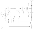
- Figure 6 illustrates a flow diagram for an exemplary method 600 for improving at least one of intelligibility or loudness of an audio program.
- the method 600 includes detecting whether at least one of a center/front signal or a surround signal is present among signals of the audio program.
- the method 600 includes receiving the audio signals of the audio program including at least left/front, center/front and right/front signals each of which includes at least some anchor components of the audio program, and, at 615, passing the left/front and right/front signals to the output.
- the method 600 includes downmixing the left/front, center/front and right/front signals to obtain left downmix and right downmix signals.
- the method 600 includes upmixing the left downmix and right downmix signals to obtain at least a center upmix signal.
- the center upmix signal includes a majority of the anchor components of the audio program including at least some anchor components of the audio program that were included in the left/front and right/front signals.
- the center upmix signal is passed to the output.
- the method 600 includes receiving the audio signals of the audio program including at least left and right signals each of which includes at least some anchor components of the audio program.
- the method 600 includes upmixing the left and right signals to obtain at least the center upmix signal, which includes a majority of the anchor components of the audio program including at least some anchor components of the audio program that were included in the left and right signals.
- the upmixing of the left and right signals may also produce left and right upmix signals and surround upmix signals (e.g., left and right surround upmix signals.)
- processing the center upmix signal or the surround upmix signal may include adjustably equalizing the center upmix signal or the surround upmix signal, adjustably varying the gain of the center upmix signal or the surround upmix signal, and limiting the center upmix signal or the surround upmix signal from exceeding a set threshold.
- processing the surround upmix signal may also include equalizing the surround upmix signal to preprocess the signal with an inverse frequency response (see Fig. 4B ) of a filter found in consumer equipment as part of a "hypersurround" effect.
- the method 600 includes downmixing at least the left and right upmix signals and the processed center upmix signal or surround upmix signal to obtain left and right downmix signals in which at least one of intelligibility or loudness has been improved over intelligibility or loudness of the left and right signals.
- the method 600 passes the left and right downmix signals to the output.
- the method 600 also includes providing the center upmix signal as an output.
- the center upmix signal may be used by an external process to process at least one of the signals of the audio program based on the center upmix signal to improve at least one of intelligibility or loudness of the audio program.
- the method 600 may include metering the center upmix signal to provide a value of intelligibility or loudness of the audio program that may serve as basis for processing at least one of the signals of the audio program to improve intelligibility or loudness of the audio program.
- the metering may be done in compliance with established standards such as EBU R128, ITU-R BS.1770, ATSC A/85, etc.
- a method for improving at least one of intelligibility or loudness of an audio program comprising: detecting whether at least one of a center/front signal or a surround signal is present among signals of the audio program; and if at least one of the center/front or the surround signal is present among the signals of the audio program: receiving the audio signals of the audio program including at least left/front, center/front and right/front signals each of which includes at least some anchor components of the audio program; downmixing the left/front, center/front and right/front signals to obtain left downmix and right downmix signals; and upmixing the left downmix and right downmix signals to obtain at least a center upmix signal, which includes a majority of the anchor components of the audio program including at least some anchor components of the audio program that were included in the left/front and right/front signals; and if at least one of the center/front or the surround signal is not present among the signals of the audio program: receiving the audio signals of the audio program including at least left and right signals each of which includes at least some anchor components of the audio program
- the method of example 1, comprising: metering the center upmix signal to provide a value of intelligibility or loudness of the audio program.
- the method of example 2 comprising: processing at least one of the signals of the audio program based on the value of intelligibility or loudness of the audio program to improve intelligibility or loudness, respectively, of the audio program.
- the method of example 1, comprising: if at least one of the center/front or the surround signal is present among the signals of the audio program: passing the left/front and right/front signals; and if at least one of the center/front or the surround signal is not present among the signals of the audio program: obtaining at least the center upmix signal and left and right upmix signals from the upmixing of the left and right signals; processing the center upmix signal, and downmixing at least the left and right upmix signals and the processed center upmix signal to obtain left and right downmix signals in which at least one of intelligibility or loudness has been adjusted over the left and right signals.
- upmixing the left downmix and right downmix signals includes: upmixing the left downmix and right downmix signals to obtain left and right upmix signals and at least one surround upmix signal that includes only non-anchor components of the audio program.
- upmixing the left and right signals includes: upmixing the left and right signals to obtain left and right upmix signals and at least one surround upmix signal that includes only non-anchor components of the audio program.
- the method of example 7, comprising: processing at least one of the center upmix signal or the at least one surround upmix signal, wherein the processing includes at least one of: equalizing the at least one surround upmix signal to preprocess the at least one surround upmix signal with an inverse frequency response of a filter found in consumer equipment as part of a hypersurround effect; adjustably equalizing the center upmix signal or the at least one surround upmix signal; adjustably varying the gain of the center upmix signal or the at least one surround upmix signal; and limiting the center upmix signal or the at least one surround upmix signal from exceeding a set threshold; and downmixing at least the left and right upmix signals and at least one of the processed surround upmix signal and the processed center upmix signal to obtain left and right downmix signals in which at least one of intelligibility or loudness has been adjusted over the left and right signals.
- the method of example 1, comprising: processing the center/front signal to improve at least one of the intelligibility or the loudness of the audio program, the processing including at least one of: adjustably equalizing the center/front signal; adjustably varying the gain of the center/front signal; and limiting the center/front signal from exceeding a set threshold.
- the method of example 1, comprising: processing at least one surround signal of the audio program, the processing including at least one of: equalizing the at least one surround signal to preprocess the at least one surround signal with an inverse frequency response of a filter found in consumer equipment as part a hypersurround effect; adjustably equalizing the at least one surround signal; adjustably varying the gain of the at least one surround signal; and limiting the at least one surround signal from exceeding a set threshold.
- a method for improving at least one of intelligibility or loudness of an audio program comprising: receiving audio signals of the audio program including at least left/front, center/front and right/front signals each of which includes at least some anchor components of the audio program; downmixing the left/front, center/front and right/front signals to obtain left downmix and right downmix signals; upmixing the left downmix and right downmix signals to obtain at least a center upmix signal that includes a majority of the anchor components of the audio program including at least some anchor components of the audio program that were included in the left/front and right/front signals; and providing the center upmix signal to process at least a center/front output signal based on the center upmix signal to improve at least one of intelligibility or loudness of the audio program.
- the method of example 11, comprising: metering the center upmix signal to provide a value of intelligibility or loudness of the audio program.
- the method of example 12 comprising: processing at least one of the signals of the audio program based on the value of intelligibility or loudness of the audio program to improve intelligibility or loudness, respectively, of the audio program.
- the method of example 11, comprising: adding at least a portion of the center upmix signal to the center/front signal to obtain the center/front output signal to improve the intelligibility of the audio program.
- upmixing the left downmix and right downmix signals includes: upmixing the left downmix and right downmix signals to obtain left and right upmix signals and at least one surround upmix signal that includes only non-anchor components of the audio program.
- the method of example 11, comprising: processing the center/front signal to improve at least one of the intelligibility or the loudness of the audio program, the processing including at least one of: adjustably equalizing the center/front signal; adjustably varying the gain of the center/front signal; and limiting the center/front signal from exceeding a set threshold.
- a method for improving at least one of intelligibility or loudness of an audio program comprising: receiving audio signals of the audio program including at least left and right signals each of which includes at least some anchor components of the audio program; upmixing the left and right signals to obtain at least a center upmix signal that includes a majority of the anchor components of the audio program including at least some anchor components of the audio program that were included in the left and right signals; and providing the center upmix signal to process left and right output signals based on the center upmix signal to improve at least one of intelligibility or loudness of the audio program.
- the method of example 18, comprising: metering the center upmix signal to provide a value of intelligibility or loudness of the audio program.
- the method of example 19, comprising: processing at least one of the signals of the audio program based on the value of intelligibility or loudness of the audio program to improve intelligibility or loudness, respectively, of the audio program.
- the method of example 18, comprising: adding at least a portion of the center upmix signal to the left and right signals to obtain the left and right output signals to improve the intelligibility of the audio program.
- the method of example 18, wherein the upmixing of the left and right signals produces at least the center upmix signal and left and right upmix signals comprising: processing the center upmix signal, and downmixing at least the left and right upmix signals and the processed center upmix signal to obtain left and right downmix signals in which at least one of intelligibility or loudness has been adjusted over the left and right signals.
- upmixing the left and right signals includes: upmixing the left and right signals to obtain left and right upmix signals and at least one surround upmix signal that includes only non-anchor components of the audio program.
- the method of example 23, comprising: processing at least one of the center upmix signal or the at least one surround upmix signal, wherein the processing includes at least one of: equalizing the at least one surround upmix signal to preprocess the at least one surround upmix signal with an inverse frequency response of a filter found in consumer equipment as part of a hypersurround effect; adjustably equalizing the center upmix signal or the at least one surround upmix signal; adjustably varying the gain of the center upmix signal or the at least one surround upmix signal; and limiting the center upmix signal or the at least one surround upmix signal from exceeding a set threshold; and downmixing at least the left and right upmix signals and at least one of the processed surround upmix signal and the processed center upmix signal to obtain left and right downmix signals in which at least one of intelligibility or loudness has been adjusted over the left and right signals.
- the method of example 18, comprising: processing at least one surround signal of the audio program, the processing including at least one of: equalizing the at least one surround signal to preprocess the at least one surround signal with an inverse frequency response of a filter found in consumer equipment as part a hypersurround effect; adjustably equalizing the at least one surround signal; adjustably varying the gain of the at least one surround signal; and limiting the at least one surround signal from exceeding a set threshold.
Landscapes
- Engineering & Computer Science (AREA)
- Physics & Mathematics (AREA)
- Signal Processing (AREA)
- Acoustics & Sound (AREA)
- General Physics & Mathematics (AREA)
- Algebra (AREA)
- Mathematical Analysis (AREA)
- Mathematical Optimization (AREA)
- Mathematical Physics (AREA)
- Pure & Applied Mathematics (AREA)
- Theoretical Computer Science (AREA)
- Multimedia (AREA)
- Stereophonic System (AREA)
- Tone Control, Compression And Expansion, Limiting Amplitude (AREA)
Description
- Programs, such as those intended for television broadcast are, in many cases, intentionally produced with variable loudness and wide dynamic range to convey emotion or a level of excitement in a given scene. For example, a movie may include a scene with the subtle chirping of a cricket and another scene with the blasting sound of a shooting cannon. Interstitial material such as commercial advertisements, on the other hand, is very often intended to convey a coherent message, and is, thus, often produced at a constant loudness, narrow dynamic range, or both. Annoying loudness disturbances commonly occur at the point of transition between the programming and the interstitial material. Thus the problem is commonly known as the "loud commercial problem." Loudness annoyances, however, are not limited to the programming/interstitial material transition, but are pervasive within the programming and the interstitial material themselves.
- Intelligibility issues arise when a component of the audio that is important for comprehension of the programming, also known as an anchor, is made inaudible or is overpowered by another component of the audio. Dialog is arguably the most common program anchor. An example is the broadcast of a tennis match on TV. A commentator narrates the action on the court while at the same time noise from the crowd and the competitors may be heard. If the crowd noise overpowers the narrator's voice, that part of the program, the narrator's voice, may be rendered unintelligible.
- Processes addressing the loud commercial problem and intelligibility issues generally attempt to measure loudness and use this measurement to adjust audio signals accordingly to improve loudness and intelligibility. Conventional techniques for measuring loudness, however, may be unsatisfactory.
- One technique for measuring loudness disclosed in
U.S. Pat. No. 7,454,331 to Vinton et al. measures the speech component of the audio exclusively to determine program loudness. This technique, however, may provide insufficient loudness measurement for programming that includes only minimal speech components. For programming that includes no speech components at all, loudness may remain unmeasured and thus unimproved. - Another conventional technique, in essence, measures loudness by measuring whatever component of the audio is the loudest for the longest period of time. This technique, however, may provide measurements that deviate from the intent of the programming or from human perception of loudness. This may be particularly true for programming that has wide dynamic range. For example, this technique may erroneously judge the loudness of a scene which contains the roaring sound of a jet flying overhead as too loud. This measurement may result in processing or adjustment of the audio program that, for example, may lower speech components of the audio to unintelligible levels.
-
US 2005/074127 A1 discloses an arrangement for processing a multi-channel audio signal having at least three original channels, in which a first downmix channel and a second downmix channel are provided, which are derived from the original channels. For a selected original channel, channel side information is calculated such that a downmix channel or a combined downmix channel including the first and second downmix channels, when weighted using the channel side information, results in an approximation of the selected original channel. The channel side information and the first and second downmix channels form output data to be transmitted to a decoder, which, in case of a low level decoder only decodes the first and second downmix channels or, in case of a high level decoder provides a full multi-channel audio signal based on the downmix channels and the channel side information. -
WO 2011/069205 A1 discloses a matrix decoder for use in a surround sound system, wherein at least four audio input signals representing an original sound field are encoded into two channel signals and said encoded signals are decoded into at least four audio output signals corresponding to the four audio input signals and have an amplitude ratio and a phase relationship. The decoder includes means for: compensating the said encoded signals for variations in perceived loudness relative to frequency associated with the encoded two channel signals due to non-linearity in human hearing response at least at some frequencies; producing steering signals in response to the phase relationship of the said compensated signals; and decoding said encoded signals to produce audio output signals corresponding to audio input signals by varying at least the amplitude ratio of said encoded signals contained in each of the output signals in response to said steering signals. - The present disclosure describes novel techniques for improving intelligibility and loudness measurement accuracy of audio programs.
- Specifically, the present disclosure describes systems and methods for better isolating sounds that humans perceive in an audio program as anchors, which are components of the audio that humans perceive as indicating direction of, for example, action displayed in a TV or movie screen. Isolating sounds that humans perceive as anchors enables focused measurement of loudness and intelligibility of the program, which, in turn, allows for the processing of the program based on the anchor-based measurements to improve loudness and/or intelligibility.
- The present disclosure also describes systems and methods whereby frequency and level processing is applied to certain components of front and rear (a.k.a. surround) audio channels to selectively enhance or diminish certain characteristics of the audio signals thus resulting in improved measurement accuracy and intelligibility. Separation of front channel and surround (a.k.a. rear) channel audio allows specific processing to be applied to each as required. Examples of processing include frequency and level equalization, often differing in type and style between the front and rear channels, but with the shared goal of preventing one component from overpowering another more important component.
- The techniques disclosed here may find particular application in the fields of broadcast and consumer audio. These techniques may be applied to stereo audio or multichannel audio of more than two channels, including but not limited to common formats such as 5.1 or 7.1 channels. These techniques may be also be applied to systems which use channel based and/or object based audio to convey additional dimensions and reality. Examples of channel and object based audio can be found in the developing MPEG-H standard, or in the recently described Dolby AC-4 system.
-
-
Figures 1A and1B illustrate high-level block diagrams of an exemplary system for improving at least one of intelligibility or loudness of an audio program. -
Figure 2 illustrates a block diagram of an exemplary encoder. -
Figure 3 illustrates a block diagram of an example processor that includes an adjustable equalizer, an adjustable gain and a limiter. -
Figure 4A illustrates a block diagram of an exemplary processor that includes a fixed equalizer that applies the frequency response shown inFigure 4B . -
Figure 4B illustrates the inverse frequency response of a filter that may be found in consumer equipment as part of a "hypersurround" effect. -
Figure 5 illustrates a block diagram of an exemplary downmixer. -
Figure 6 illustrates a flow diagram for an example method for improving at least one of intelligibility or loudness of an audio program. -
Figures 1A and1B illustrate high-level block diagrams of anexemplary system 100 for improving at least one of intelligibility or loudness of an audio program. - The
system 100 includes aninput 101 that includes a set of terminals including left front Lf, right front Rf, center front Cf, low frequency effects LFE, left surround Ls, and right surround Rs corresponding to a 5.1 channel format. Thesystem 100 also includes anoutput 102 that includes a set of terminals including left front Lf', right front Rf', center front Cf', low frequency effects LFE, left surround Ls', and right surround Rs' corresponding to a 5.1 channel format. While in the embodiments ofFigures 1A and1B theinput 101 and theoutput 102 each includes six terminals corresponding to a 5.1 channel format, in other embodiments, theinput 101 and theoutput 102 may include more or less than six terminals corresponding to formats other than a 5.1 channel format (e.g., 2-channel stereo, 3.1, 7.1, etc.) - In the embodiment of
Figure 1A theinput 101 receives six signals Lf, Rf, Cf, LFE, Ls, and Rs. In the embodiment ofFigure 1B theinput 101 receives two signals L and R. - The
system 100 may include adetector 123 that detects whether at least one of the Cf, Ls, or Rs signals is present among signals of the audio program received by theinput 101. That is, thedetector 123 determines whether the audio program received by theinput 101 is in a multichannel format (e.g., 3.1, 5.1, 7.1, etc.) or in a two channel (e.g., stereo) format. As described in more detail below, thesystem 100 performs differently depending on whether the audio program received by theinput 101 is in a multichannel format or in a stereo format. - The present disclosure first describes the
system 100 in the context ofFigure 1A (i.e., thedetector 123 has determined that the audio program received at theinput 101 is in a 5.1 multichannel format.) - The
system 100 includes amatrix encoder 105 that receives the Lf, Cf, and Rf signals and encodes (i.e., combines or downmixes) the signals to obtain left downmix Ld and right downmix Rd signals. Theencoder 105 may be one of many encoders or downmixers known in the art. -
Figure 2 illustrates a block diagram of anexemplary encoder 105. In the embodiment ofFigure 2 , theencoder 105 includes a gain adjust 206 and twosummers summer 207 sums Lf to the gain adjusted Cf signal to obtain Ld. Thesummer 208 sums Rf to the gain adjusted Cf signal to obtain Rd. Theencoder 105 may be one of many encoders or downmixers known in the art other than the one illustrated inFigure 2 . - Returning to
Figure 1A , thesystem 100 includes amatrix decoder 110 that receives the Ld and Rd signals and decodes (e.g., separates or upmixes) the signals to obtain left upmix Lu, right upmix Ru, center upmix Cu, and surround upmix Su. Thedecoder 110 may be one of many decoders or upmixers known in the art an. An example of a decoder that may serve as thedecoder 110 is described inU.S. Pat. No. 5,046,098 to Mandell . - In one embodiment (not shown), the
system 100 includes a matrix decoder that, instead of the surround Su signal, outputs left/surround upmix and right/surround upmix signals. In another embodiment (not shown), thesystem 100 includes a matrix decoder that does not output a surround upmix Su signal, but only Lu, Ru and Cu. In yet other embodiments, thesystem 100 includes a matrix decoder that center upmix Cu only. - Multichannel audio of more than two channels presents another challenge in the increasing use of so-called dialog panning where dialog may be present, in addition to the center front Cf channel, in the left front Lf and or right front Rf channels. This may require additional techniques to combine the Lf, Rf, and Cf channels prior to further decomposition and may result in the front dominant signals, including speech if present, to be directed primarily to one channel. For multichannel audio the above-described first downmix then upmix technique tends to direct any audio that is common between left front Lf and center front Cf and any audio that is common between right front Rf and center front Cf into just the center upmix Cu signal. Thus the resulting Cu signal includes the vast majority of the anchor elements even for programs in which the original left front Lf and/or right front Rf may also contain anchor elements (e.g., left to right/right to left dialog panning).
- The
system 100 may also include theprocessor 115 that may process the Cu signal to filter out information above and below certain frequencies that are not part of those frequencies normally found in dialog or considered anchors. Theprocessor 115 may alternatively or in addition process the Cu signal to enhance speech formants and increase the peak to trough ratio both of which can improve intelligibility. - The Cu signal (or the processed Cu signal) may be provided via the
output 102 for use by processes that may benefit from better anchor isolation. The Cu signal (or the processed Cu signal) may also be used to process at least one of the signals of the audio program based on the Cu signal to improve intelligibility or loudness of the audio program. For example, the Cu signal may be added to the Cf signal (not shown) to improve intelligibility of the audio program. - The
system 100 may also include or be connected to ameter 113. Themeter 113 may be compliant with a loudness measurement standard (e.g., EBU R128, ITU-R BS.1770, ATSC A/85, etc.) and the Cu signal (or the processed Cu signal) may be available as an input to themeter 113 so that loudness of the audio program may be measured very precisely. The output of themeter 113 may be used by processes that may benefit from better loudness measurement. The output of themeter 113 may also be used to process at least one of the signals of the audio program based on the Cu signal to improve intelligibility or loudness of the audio program. - As described above,
detector 123 determines signal presence above threshold in the center front Cf, left surround Ls, or right surround Rs channels. If thedetector 123 determines signal presence above threshold in the center front Cf, left surround Ls, or right surround Rs channels, thedetector 123 may transmit asignal 124 to theswitches 125 to allow left front Lf and right front Rf input audio to pass directly frominput 101 to theoutput 102. - For the case of multichannel audio, the center front signal Cf often contains most of the dialog present in a program. Regarding the center front channel Cf, the
system 100 may also include aprocessor 122 that processes the Cf signal. -
Figure 3 illustrates a block diagram of anexample processor 122 that includes anadjustable equalizer 302, anadjustable gain 303 and alimiter 304. Theprocessor 122 therefore enables variable equalization, variable gain, and limiting to be applied to the center channel Cf. The adjustable equalizer (EQ) 302 such as a parametric equalizer may be used to modify the frequency response of the Cf signal. Thevariable gain stage 303 may apply positive or negative gain as desired. Thelimiter 304 such as, for example, a peak limiter may prevent audio from exceeding a set threshold before being output as Cf'. In one embodiment (not shown), one or more of theadjustable equalizer 302, theadjustable gain 303 and thelimiter 304 is controlled based on the Cu signal such that the Cf signal is processed based on the Cu signal to, for example, improve intelligibility or loudness of the audio program. - Returning to
Figure 1A , for the case of multichannel audio, Ls and Rs often contain crowd noise, effects, and other information which may be out of phase and time alignment with the front channels Lf and Rf. Regarding the left surround Ls and right surround Rs signals, thesystem 100 may also includeprocessors 121a-b that process the Ls and Rs signals. -
Figure 4A illustrates a block diagram of anexemplary processor 121. Theprocessor 121 includes a fixed equalizer (EQ) 402 that may be used to apply the frequency response shown inFigure 4B which is the inverse frequency response of a filter that may be found in consumer equipment as part of a "hypersurround" effect. An example of such a "hypersurround" effect is described inU.S. Pat. Nos. 4,748,669 and5,892,830 to Klayman . TheEQ 402 may be followed by avariable gain stage 403 which can apply positive or negative gain as desired. The frequency response of this signal may also be modified by an adjustable equalizer (EQ) 404 such as a parametric equalizer, and alimiter 405 such as a peak limiter to prevent audio from exceeding a set threshold. - Back to
Figure 1A , thesystem 100 may also include adelay 114 that works in conjunction with one or more of theprocessors 121a-b and 122 to delay the Lf and Rf signals to compensate for any delays introduced in the Cf', Ls' and Rs' signals by theprocessors 121a-b and 122. - The present disclosure now describes the
system 100 in the context ofFigure 1B (i.e., thedetector 123 has determined that the audio program received at theinput 101 is in a two-channel stereo format.) Multichannel signals of more than two channels, such as in formats of 5.1 or 7.1 channels, already have the front and surround channels separated, but two channel stereo content has the front and rear information combined and thus requires additional processing. - As discussed above, in the embodiment of
Figure 1B theinput 101 receives two signals L and R. Thematrix encoder 105 receives the L and R signals and outputs left downmix Ld and right downmix Rd signals, which are then passed to thematrix decoder 110. In this case, however, since a one-to-one relationship exists between inputs and outputs signals, the L and R signals may simply be passed throughencoder 105 as the Ld and Rd signals, respectively. In one embodiment (not shown), thesystem 100 does not include theencoder 105 and the L and R signals are passed directly as the Ld and Rd signals to thematrix decoder 110. - The
matrix decoder 110 receives the Ld and Rd signals and decodes (e.g., separates or upmixes) the signals to obtain left upmix Lu, right upmix Ru, center upmix Cu, and surround upmix Su. The simplest method to accomplish front/rear separation in two channel stereo signals is by creating L+R, or Front, and L-R, or Rear audio signals. However, applying correction individually to just these signals may result in undesired audible artifacts such as stereo image narrowing. Through the use of matrix decoding or upmixing, further decomposing the front and surround into left front upmix Lu, center upmix Cu, right front upmix Ru, and surround upmix Su (or left surround and right surround) enables more finely grained control to be applied. Further decomposing the front and surround into left front upmix Lu, center upmix Cu, right front upmix Ru, and surround upmix Su (or left surround and right surround) also further isolates Cu, which often contains the dialog or other anchor portions of a program. - The Cu signal (or the Cu signal processed by the
processor 115 to filter out frequencies of the Cu signal that are not part of those frequencies normally found in dialog or considered anchors or to enhance speech formants or increase the peak to trough ratio) may be output via theoutput 102 for use by processes that may benefit from better anchor isolation. Thesystem 100 may also include themeter 113 and the Cu signal (or the processed Cu signal) may be available as an input to themeter 113 so that loudness of the audio program may be measured very precisely. The Cu signal (or the processed Cu signal) or the output of themeter 113 may also be used to process at least one of the signals of the audio program based on the Cu signal to improve intelligibility or loudness of the audio program. For example, the Cu signal may be added to the L and R signals to improve intelligibility of the audio program. - In another example and as illustrated in
Figure 1B , the Cu signal or the Cu signal as processed by theprocessor 115 may be applied to asecond matrix encoder 117 together with the other outputs of thematrix decoder 110. In the embodiment ofFigure 1B , the Lu, Ru, Cu and Su signals are applied to matrix encoder ordownmixer 117 to produce left downmix Ld' and right downmix Rd' signals. -
Figure 5 illustrates a block diagram of an exemplary downmixer orencoder 117. In the embodiment ofFigure 5 , theencoder 117 includes gain adjusts 505 and 506 that adjust the gain (e.g., by -3dB) of the Cu signal and the Su signals, respectively. Theencoder 117 also includessummers encoder 117 also includes thesummers encoder 117 may be one of many encoders or downmixers known in the art other than the one illustrated inFigure 5 . - Returning to
Figure 1B , thedecoder 110 may output a different number of signals from those shown. In those embodiments (not shown) in which thedecoder 110 outputs more or less than the illustrated outputs Lu, Ru, Cu and Su (for example where thedecoder 110 outputs only Lu, Ru and Cu or where thedecoder 110 outputs left surround and right surround in addition to Lu, Ru and Cu), the outputs of thedecoder 110 as applicable are applied to theencoder 117 to produce the left downmix Ld' and right downmix Rd' signals. - In one embodiment, the
system 100 may also include theprocessor 121c that processes the Su signal. As described above,Figure 4A illustrates a block diagram of theexemplary processor 121, which includes the fixed equalizer (EQ) 402 that may be used to apply the frequency response shown inFigure 4B which is the inverse frequency response of a filter that may be found in consumer equipment as part of a "hypersurround" effect. TheEQ 402 may be followed by avariable gain stage 403 which can apply positive or negative gain as desired. The frequency response of this signal may also be modified by an adjustable equalizer (EQ) 404 such as a parametric equalizer, and alimiter 405 such as a peak limiter to prevent audio from exceeding a set threshold. - The
system 100 may also include adelay 116 that works in conjunction with one or more of theprocessors processors - As described above, the
detector 123 determines signal presence above threshold in the center front Cf, left surround Ls, or right surround Rs channels. If thedetector 123 determines no signal presence above threshold in the center front Cf, left surround Ls, or right surround Rs channels (i.e., stereo), thedetector 123 may transmit thesignal 124 to theswitches 125 to pass the Ld' and Rd' to theoutput 102. - Example methods may be better appreciated with reference to the flow diagram of
Figure 6 . -
Figure 6 illustrates a flow diagram for anexemplary method 600 for improving at least one of intelligibility or loudness of an audio program. At 605, themethod 600 includes detecting whether at least one of a center/front signal or a surround signal is present among signals of the audio program. - If at least one of the center/front or the surround signal is present among the signals of the audio program, at 610, the
method 600 includes receiving the audio signals of the audio program including at least left/front, center/front and right/front signals each of which includes at least some anchor components of the audio program, and, at 615, passing the left/front and right/front signals to the output. - At 620, the
method 600 includes downmixing the left/front, center/front and right/front signals to obtain left downmix and right downmix signals. At 625, themethod 600 includes upmixing the left downmix and right downmix signals to obtain at least a center upmix signal. The center upmix signal includes a majority of the anchor components of the audio program including at least some anchor components of the audio program that were included in the left/front and right/front signals. At 655, the center upmix signal is passed to the output. - Back to 605, if at least one of the center/front or the surround signal is not present among the signals of the audio program, at 630, the
method 600 includes receiving the audio signals of the audio program including at least left and right signals each of which includes at least some anchor components of the audio program. At 635, themethod 600 includes upmixing the left and right signals to obtain at least the center upmix signal, which includes a majority of the anchor components of the audio program including at least some anchor components of the audio program that were included in the left and right signals. Along with the center upmix signal, the upmixing of the left and right signals may also produce left and right upmix signals and surround upmix signals (e.g., left and right surround upmix signals.) - At 640, the
method 600 includes processing at least one of the center upmix signal or a surround upmix signal. For example, processing the center upmix signal or the surround upmix signal may include adjustably equalizing the center upmix signal or the surround upmix signal, adjustably varying the gain of the center upmix signal or the surround upmix signal, and limiting the center upmix signal or the surround upmix signal from exceeding a set threshold. Processing the surround upmix signal may also include equalizing the surround upmix signal to preprocess the signal with an inverse frequency response (seeFig. 4B ) of a filter found in consumer equipment as part of a "hypersurround" effect. - At 645, the
method 600 includes downmixing at least the left and right upmix signals and the processed center upmix signal or surround upmix signal to obtain left and right downmix signals in which at least one of intelligibility or loudness has been improved over intelligibility or loudness of the left and right signals. At 650, themethod 600 passes the left and right downmix signals to the output. At 655, themethod 600 also includes providing the center upmix signal as an output. - The center upmix signal may be used by an external process to process at least one of the signals of the audio program based on the center upmix signal to improve at least one of intelligibility or loudness of the audio program.
- For example, the
method 600 may include metering the center upmix signal to provide a value of intelligibility or loudness of the audio program that may serve as basis for processing at least one of the signals of the audio program to improve intelligibility or loudness of the audio program. The metering may be done in compliance with established standards such as EBU R128, ITU-R BS.1770, ATSC A/85, etc. - A method for improving at least one of intelligibility or loudness of an audio program, the method comprising: detecting whether at least one of a center/front signal or a surround signal is present among signals of the audio program; and if at least one of the center/front or the surround signal is present among the signals of the audio program: receiving the audio signals of the audio program including at least left/front, center/front and right/front signals each of which includes at least some anchor components of the audio program; downmixing the left/front, center/front and right/front signals to obtain left downmix and right downmix signals; and upmixing the left downmix and right downmix signals to obtain at least a center upmix signal, which includes a majority of the anchor components of the audio program including at least some anchor components of the audio program that were included in the left/front and right/front signals; and if at least one of the center/front or the surround signal is not present among the signals of the audio program: receiving the audio signals of the audio program including at least left and right signals each of which includes at least some anchor components of the audio program; and upmixing the left and right signals to obtain at least the center upmix signal, which includes a majority of the anchor components of the audio program including at least some anchor components of the audio program that were included in the left and right signals; and providing the center upmix signal to process at least one of the signals of the audio program based on the center upmix signal to improve at least one of intelligibility or loudness of the audio program.
- The method of example 1, comprising: metering the center upmix signal to provide a value of intelligibility or loudness of the audio program.
- The method of example 2, comprising: processing at least one of the signals of the audio program based on the value of intelligibility or loudness of the audio program to improve intelligibility or loudness, respectively, of the audio program.
- The method of example 2, wherein the metering is compliant with at least one of: EBU R128; ITU-R BS.1770; and ATSC A/85.
- The method of example 1, comprising: if at least one of the center/front or the surround signal is present among the signals of the audio program: passing the left/front and right/front signals; and if at least one of the center/front or the surround signal is not present among the signals of the audio program: obtaining at least the center upmix signal and left and right upmix signals from the upmixing of the left and right signals; processing the center upmix signal, and downmixing at least the left and right upmix signals and the processed center upmix signal to obtain left and right downmix signals in which at least one of intelligibility or loudness has been adjusted over the left and right signals.
- The method of example 1, wherein the upmixing the left downmix and right downmix signals includes: upmixing the left downmix and right downmix signals to obtain left and right upmix signals and at least one surround upmix signal that includes only non-anchor components of the audio program.
- The method of example 1, wherein the upmixing the left and right signals includes: upmixing the left and right signals to obtain left and right upmix signals and at least one surround upmix signal that includes only non-anchor components of the audio program.
- The method of example 7, comprising: processing at least one of the center upmix signal or the at least one surround upmix signal, wherein the processing includes at least one of: equalizing the at least one surround upmix signal to preprocess the at least one surround upmix signal with an inverse frequency response of a filter found in consumer equipment as part of a hypersurround effect; adjustably equalizing the center upmix signal or the at least one surround upmix signal; adjustably varying the gain of the center upmix signal or the at least one surround upmix signal; and limiting the center upmix signal or the at least one surround upmix signal from exceeding a set threshold; and downmixing at least the left and right upmix signals and at least one of the processed surround upmix signal and the processed center upmix signal to obtain left and right downmix signals in which at least one of intelligibility or loudness has been adjusted over the left and right signals.
- The method of example 1, comprising: processing the center/front signal to improve at least one of the intelligibility or the loudness of the audio program, the processing including at least one of: adjustably equalizing the center/front signal; adjustably varying the gain of the center/front signal; and limiting the center/front signal from exceeding a set threshold.
- The method of example 1, comprising: processing at least one surround signal of the audio program, the processing including at least one of: equalizing the at least one surround signal to preprocess the at least one surround signal with an inverse frequency response of a filter found in consumer equipment as part a hypersurround effect; adjustably equalizing the at least one surround signal; adjustably varying the gain of the at least one surround signal; and limiting the at least one surround signal from exceeding a set threshold.
- A method for improving at least one of intelligibility or loudness of an audio program, the method comprising: receiving audio signals of the audio program including at least left/front, center/front and right/front signals each of which includes at least some anchor components of the audio program; downmixing the left/front, center/front and right/front signals to obtain left downmix and right downmix signals; upmixing the left downmix and right downmix signals to obtain at least a center upmix signal that includes a majority of the anchor components of the audio program including at least some anchor components of the audio program that were included in the left/front and right/front signals; and providing the center upmix signal to process at least a center/front output signal based on the center upmix signal to improve at least one of intelligibility or loudness of the audio program.
- The method of example 11, comprising: metering the center upmix signal to provide a value of intelligibility or loudness of the audio program.
- The method of example 12, comprising: processing at least one of the signals of the audio program based on the value of intelligibility or loudness of the audio program to improve intelligibility or loudness, respectively, of the audio program.
- The method of example 12, wherein the metering is compliant with at least one of: EBU R128; ITU-R BS.1770; and ATSC A/85.
- The method of example 11, comprising: adding at least a portion of the center upmix signal to the center/front signal to obtain the center/front output signal to improve the intelligibility of the audio program.
- The method of example 11, wherein the upmixing the left downmix and right downmix signals includes: upmixing the left downmix and right downmix signals to obtain left and right upmix signals and at least one surround upmix signal that includes only non-anchor components of the audio program.
- The method of example 11, comprising: processing the center/front signal to improve at least one of the intelligibility or the loudness of the audio program, the processing including at least one of: adjustably equalizing the center/front signal; adjustably varying the gain of the center/front signal; and limiting the center/front signal from exceeding a set threshold.
- A method for improving at least one of intelligibility or loudness of an audio program, the method comprising: receiving audio signals of the audio program including at least left and right signals each of which includes at least some anchor components of the audio program; upmixing the left and right signals to obtain at least a center upmix signal that includes a majority of the anchor components of the audio program including at least some anchor components of the audio program that were included in the left and right signals; and providing the center upmix signal to process left and right output signals based on the center upmix signal to improve at least one of intelligibility or loudness of the audio program.
- The method of example 18, comprising: metering the center upmix signal to provide a value of intelligibility or loudness of the audio program.
- The method of example 19, comprising: processing at least one of the signals of the audio program based on the value of intelligibility or loudness of the audio program to improve intelligibility or loudness, respectively, of the audio program.
- The method of example 18, comprising: adding at least a portion of the center upmix signal to the left and right signals to obtain the left and right output signals to improve the intelligibility of the audio program.
- The method of example 18, wherein the upmixing of the left and right signals produces at least the center upmix signal and left and right upmix signals, the method comprising: processing the center upmix signal, and downmixing at least the left and right upmix signals and the processed center upmix signal to obtain left and right downmix signals in which at least one of intelligibility or loudness has been adjusted over the left and right signals.
- The method of example 18, wherein the upmixing the left and right signals includes: upmixing the left and right signals to obtain left and right upmix signals and at least one surround upmix signal that includes only non-anchor components of the audio program.
- The method of example 23, comprising: processing at least one of the center upmix signal or the at least one surround upmix signal, wherein the processing includes at least one of: equalizing the at least one surround upmix signal to preprocess the at least one surround upmix signal with an inverse frequency response of a filter found in consumer equipment as part of a hypersurround effect; adjustably equalizing the center upmix signal or the at least one surround upmix signal; adjustably varying the gain of the center upmix signal or the at least one surround upmix signal; and limiting the center upmix signal or the at least one surround upmix signal from exceeding a set threshold; and downmixing at least the left and right upmix signals and at least one of the processed surround upmix signal and the processed center upmix signal to obtain left and right downmix signals in which at least one of intelligibility or loudness has been adjusted over the left and right signals.
- The method of example 18, comprising: processing at least one surround signal of the audio program, the processing including at least one of: equalizing the at least one surround signal to preprocess the at least one surround signal with an inverse frequency response of a filter found in consumer equipment as part a hypersurround effect; adjustably equalizing the at least one surround signal; adjustably varying the gain of the at least one surround signal; and limiting the at least one surround signal from exceeding a set threshold.
Claims (15)
- A system (100) for improving at least one of intelligibility or loudness of an audio program, the system comprising:a matrix encoder (105) configured to receive audio signals of the audio program including at least one of a) Lf, Rf and Cf signals or b) left and right signals each of which includes at least some components of the audio program and to downmix the received audio signals to obtain left downmix and right downmix signals;a matrix decoder (110) configured to upmix the left downmix and right downmix signals to obtain at least a center upmix signal, which includes a majority of the components of the said at least some components of the audio program that were included in the at least one of a) the Lf, Rf and Cf signals or b) the left and right signals; anda system output (102) configured to provide the center upmix signal; andan adder configured to add a portion of the center upmix signal to one or more of:a) the left and right signals, andb) the Cf signal of the audio program.
- The system of claim 1, further comprising a processor for: (i) processing the Cf signal based on the center upmix signal to improve intelligibility or loudness of the audio program; or (ii) adding the center upmix signal to the left and right signals to improve intelligibility of the audio program.
- The system of claim 1, comprising:a meter (113) operatively connected to the system output (102) and configured to meter the center upmix signal to provide a value of intelligibility or loudness of the audio program.
- The system of claim 3, comprising:a processor configured to process at least one of the signals of the audio program based on the value of intelligibility or loudness of the audio program to improve intelligibility or loudness, respectively, of the audio program.
- The system of claim 4, wherein the meter is compliant with at least one of:EBU R128;ITU-R BS.1770; andATSC A/85.
- The system of claim 1, wherein the matrix decoder (110) is configured to upmix the left downmix and right downmix signals to obtain at least the center upmix signal and left and right upmix signals.
- The system of claim 6, comprising:a processor (115) configured to process the center upmix signal; anda second encoder (117) configured to downmix at least the processed center upmix signal and the left and right upmix signals to obtain left and right downmix signals whose intelligibility or loudness is improved over the intelligibility or loudness, respectively, of the left and right signals.
- The system of claim 1, wherein the matrix decoder (110) is configured to upmix the left downmix and right downmix signals to obtain at least the center upmix signal, a surround upmix signal and left and right upmix signals.
- The system of claim 8, comprising:a processor (115) configured to process the center upmix signal; anda second encoder (117) configured to downmix at least the processed center upmix signal, the surround upmix signal and the left and right upmix signals to obtain left and right downmix signals whose intelligibility or loudness is improved over the intelligibility or loudness, respectively, of the left and right signals.
- The system of claim 9, comprising:a detector (123) configured to detect whether at least one of a Cf signal or a surround signal is present among signals of the audio program;at least one switch (125) operatively connected to the detector and configured to pass the Lf and Rf signals to the system output (102) if at least one of the Cf or the surround signal is present among the signals of the audio program, the at least one switch further configured to pass the left and right downmix signals if at least one of the Cf or the surround signal is not present among the signals of the audio program.
- The system of claim 8, comprising:a processor (121c) configured to preprocess the surround upmix signal with an inverse frequency response of a filter found in consumer equipment as part of a hypersurround effect; anda second encoder (117) configured to downmix at least the processed center upmix signal, the surround upmix signal and the left and right upmix signals to obtain left and right downmix signals.
- The system of claim 1, wherein the matrix encoder (105) receives a Cf signal of the audio program, the system comprising:a processor (122) configured to process the Cf signal to improve at least one of the intelligibility or the loudness of the audio program, the processing including at least one of:adjustably equalizing the Cf signal;adjustably varying the gain of the Cf signal; andlimiting the Cf signal from exceeding a set threshold.
- The system of claim 1, wherein the matrix encoder (105) receives at least one surround signal of the audio program, the system comprising:a processor (121a, 121b) configured to process the at least one surround signal including at least one of:equalizing the at least one surround signal to preprocess the at least one surround signal with an inverse frequency response of a filter found in consumer equipment as part a hypersurround effect;adjustably equalizing the at least one surround signal;adjustably varying the gain of the at least one surround signal; andlimiting the at least one surround signal from exceeding a set threshold.
- The system of any preceding claim, wherein the at least some components of the audio program comprise dialog components of the audio program.
- The system of claim 1, comprising:a dialog enhancer (115) configured to enhance dialog of the audio program based on the center upmix signal.
Applications Claiming Priority (1)
| Application Number | Priority Date | Filing Date | Title |
|---|---|---|---|
| US14/167,479 US9344825B2 (en) | 2014-01-29 | 2014-01-29 | At least one of intelligibility or loudness of an audio program |
Publications (3)
| Publication Number | Publication Date |
|---|---|
| EP2903301A2 EP2903301A2 (en) | 2015-08-05 |
| EP2903301A3 EP2903301A3 (en) | 2015-09-09 |
| EP2903301B1 true EP2903301B1 (en) | 2016-11-16 |
Family
ID=52434536
Family Applications (1)
| Application Number | Title | Priority Date | Filing Date |
|---|---|---|---|
| EP15151272.0A Active EP2903301B1 (en) | 2014-01-29 | 2015-01-15 | Improving at least one of intelligibility or loudness of an audio program |
Country Status (4)
| Country | Link |
|---|---|
| US (1) | US9344825B2 (en) |
| EP (1) | EP2903301B1 (en) |
| AU (1) | AU2015200054A1 (en) |
| CA (1) | CA2880126C (en) |
Families Citing this family (28)
| Publication number | Priority date | Publication date | Assignee | Title |
|---|---|---|---|---|
| US10848118B2 (en) | 2004-08-10 | 2020-11-24 | Bongiovi Acoustics Llc | System and method for digital signal processing |
| US8284955B2 (en) | 2006-02-07 | 2012-10-09 | Bongiovi Acoustics Llc | System and method for digital signal processing |
| US9413321B2 (en) | 2004-08-10 | 2016-08-09 | Bongiovi Acoustics Llc | System and method for digital signal processing |
| US11431312B2 (en) | 2004-08-10 | 2022-08-30 | Bongiovi Acoustics Llc | System and method for digital signal processing |
| US10158337B2 (en) | 2004-08-10 | 2018-12-18 | Bongiovi Acoustics Llc | System and method for digital signal processing |
| US11202161B2 (en) | 2006-02-07 | 2021-12-14 | Bongiovi Acoustics Llc | System, method, and apparatus for generating and digitally processing a head related audio transfer function |
| US9615189B2 (en) | 2014-08-08 | 2017-04-04 | Bongiovi Acoustics Llc | Artificial ear apparatus and associated methods for generating a head related audio transfer function |
| US10701505B2 (en) | 2006-02-07 | 2020-06-30 | Bongiovi Acoustics Llc. | System, method, and apparatus for generating and digitally processing a head related audio transfer function |
| US10848867B2 (en) | 2006-02-07 | 2020-11-24 | Bongiovi Acoustics Llc | System and method for digital signal processing |
| US9348904B2 (en) | 2006-02-07 | 2016-05-24 | Bongiovi Acoustics Llc. | System and method for digital signal processing |
| US10069471B2 (en) | 2006-02-07 | 2018-09-04 | Bongiovi Acoustics Llc | System and method for digital signal processing |
| US9883318B2 (en) | 2013-06-12 | 2018-01-30 | Bongiovi Acoustics Llc | System and method for stereo field enhancement in two-channel audio systems |
| US9398394B2 (en) | 2013-06-12 | 2016-07-19 | Bongiovi Acoustics Llc | System and method for stereo field enhancement in two-channel audio systems |
| US9264004B2 (en) | 2013-06-12 | 2016-02-16 | Bongiovi Acoustics Llc | System and method for narrow bandwidth digital signal processing |
| US9397629B2 (en) | 2013-10-22 | 2016-07-19 | Bongiovi Acoustics Llc | System and method for digital signal processing |
| US9906858B2 (en) | 2013-10-22 | 2018-02-27 | Bongiovi Acoustics Llc | System and method for digital signal processing |
| US9615813B2 (en) | 2014-04-16 | 2017-04-11 | Bongiovi Acoustics Llc. | Device for wide-band auscultation |
| US10639000B2 (en) | 2014-04-16 | 2020-05-05 | Bongiovi Acoustics Llc | Device for wide-band auscultation |
| US10820883B2 (en) | 2014-04-16 | 2020-11-03 | Bongiovi Acoustics Llc | Noise reduction assembly for auscultation of a body |
| US9564146B2 (en) * | 2014-08-01 | 2017-02-07 | Bongiovi Acoustics Llc | System and method for digital signal processing in deep diving environment |
| US9638672B2 (en) | 2015-03-06 | 2017-05-02 | Bongiovi Acoustics Llc | System and method for acquiring acoustic information from a resonating body |
| US9906867B2 (en) | 2015-11-16 | 2018-02-27 | Bongiovi Acoustics Llc | Surface acoustic transducer |
| US9621994B1 (en) | 2015-11-16 | 2017-04-11 | Bongiovi Acoustics Llc | Surface acoustic transducer |
| US9820073B1 (en) | 2017-05-10 | 2017-11-14 | Tls Corp. | Extracting a common signal from multiple audio signals |
| US11211043B2 (en) | 2018-04-11 | 2021-12-28 | Bongiovi Acoustics Llc | Audio enhanced hearing protection system |
| US11616482B2 (en) | 2018-06-22 | 2023-03-28 | Dolby Laboratories Licensing Corporation | Multichannel audio enhancement, decoding, and rendering in response to feedback |
| WO2020028833A1 (en) | 2018-08-02 | 2020-02-06 | Bongiovi Acoustics Llc | System, method, and apparatus for generating and digitally processing a head related audio transfer function |
| CN115966216A (en) * | 2022-12-21 | 2023-04-14 | 上海哔哩哔哩科技有限公司 | Audio stream processing method and device |
Family Cites Families (11)
| Publication number | Priority date | Publication date | Assignee | Title |
|---|---|---|---|---|
| US5046098A (en) | 1985-03-07 | 1991-09-03 | Dolby Laboratories Licensing Corporation | Variable matrix decoder with three output channels |
| US4748669A (en) | 1986-03-27 | 1988-05-31 | Hughes Aircraft Company | Stereo enhancement system |
| US5661808A (en) | 1995-04-27 | 1997-08-26 | Srs Labs, Inc. | Stereo enhancement system |
| US7454331B2 (en) | 2002-08-30 | 2008-11-18 | Dolby Laboratories Licensing Corporation | Controlling loudness of speech in signals that contain speech and other types of audio material |
| US7447317B2 (en) | 2003-10-02 | 2008-11-04 | Fraunhofer-Gesellschaft Zur Foerderung Der Angewandten Forschung E.V | Compatible multi-channel coding/decoding by weighting the downmix channel |
| US7729775B1 (en) | 2006-03-21 | 2010-06-01 | Advanced Bionics, Llc | Spectral contrast enhancement in a cochlear implant speech processor |
| CN101960516B (en) | 2007-09-12 | 2014-07-02 | 杜比实验室特许公司 | Speech enhancement |
| US8705769B2 (en) * | 2009-05-20 | 2014-04-22 | Stmicroelectronics, Inc. | Two-to-three channel upmix for center channel derivation |
| US9324337B2 (en) * | 2009-11-17 | 2016-04-26 | Dolby Laboratories Licensing Corporation | Method and system for dialog enhancement |
| EP2510709A4 (en) | 2009-12-10 | 2015-04-08 | Reality Ip Pty Ltd | Improved matrix decoder for surround sound |
| US20140123166A1 (en) * | 2012-10-26 | 2014-05-01 | Tektronix, Inc. | Loudness log for recovery of gated loudness measurements and associated analyzer |
-
2014
- 2014-01-29 US US14/167,479 patent/US9344825B2/en active Active
-
2015
- 2015-01-07 AU AU2015200054A patent/AU2015200054A1/en not_active Abandoned
- 2015-01-15 EP EP15151272.0A patent/EP2903301B1/en active Active
- 2015-01-27 CA CA2880126A patent/CA2880126C/en active Active
Also Published As
| Publication number | Publication date |
|---|---|
| CA2880126C (en) | 2018-07-10 |
| US20150215720A1 (en) | 2015-07-30 |
| EP2903301A2 (en) | 2015-08-05 |
| US9344825B2 (en) | 2016-05-17 |
| AU2015200054A1 (en) | 2015-08-13 |
| EP2903301A3 (en) | 2015-09-09 |
| CA2880126A1 (en) | 2015-07-29 |
Similar Documents
| Publication | Publication Date | Title |
|---|---|---|
| CA2880126C (en) | Improving at least one of intelligibility or loudness of an audio program | |
| KR102686742B1 (en) | Object-based audio signal balancing | |
| KR101538623B1 (en) | A method for mixing two input audio signals, and a decoder and computer-readable storage medium for performing the method, and a device for mixing input audio signals | |
| US9532156B2 (en) | Apparatus and method for sound stage enhancement | |
| US8180062B2 (en) | Spatial sound zooming | |
| US8594817B2 (en) | Method and an apparatus for processing an audio signal | |
| US9449603B2 (en) | Multi-channel audio encoder and method for encoding a multi-channel audio signal | |
| US8706508B2 (en) | Audio decoding apparatus and audio decoding method performing weighted addition on signals | |
| US9129593B2 (en) | Multi channel audio processing | |
| US20190222951A1 (en) | Processing object-based audio signals | |
| US20100087938A1 (en) | Method and an apparatus for processing an audio signal | |
| KR20160037219A (en) | Hybrid waveform-coded and parametric-coded speech enhancement | |
| US11743646B2 (en) | Signal processing apparatus and method, and program to reduce calculation amount based on mute information | |
| KR20110042305A (en) | Audio signal processing method and apparatus | |
| KR20090067550A (en) | Audio matrix encoding and decoding method and apparatus | |
| Shirley | Improving television sound for people with hearing impairments | |
| JP2010118978A (en) | Controller of localization of sound, and method of controlling localization of sound | |
| JP2009159020A (en) | Signal processing apparatus, signal processing method, and program | |
| JPWO2016039168A1 (en) | Audio processing apparatus and method | |
| US11330370B2 (en) | Loudness control methods and devices | |
| US10306391B1 (en) | Stereophonic to monophonic down-mixing | |
| HK1186585B (en) | Audio stream mixing with dialog level normalization | |
| HK1222470B (en) | Hybrid waveform-coded and parametric-coded speech enhancement |
Legal Events
| Date | Code | Title | Description |
|---|---|---|---|
| PUAI | Public reference made under article 153(3) epc to a published international application that has entered the european phase |
Free format text: ORIGINAL CODE: 0009012 |
|
| 17P | Request for examination filed |
Effective date: 20150115 |
|
| AK | Designated contracting states |
Kind code of ref document: A2 Designated state(s): AL AT BE BG CH CY CZ DE DK EE ES FI FR GB GR HR HU IE IS IT LI LT LU LV MC MK MT NL NO PL PT RO RS SE SI SK SM TR |
|
| AX | Request for extension of the european patent |
Extension state: BA ME |
|
| PUAL | Search report despatched |
Free format text: ORIGINAL CODE: 0009013 |
|
| AK | Designated contracting states |
Kind code of ref document: A3 Designated state(s): AL AT BE BG CH CY CZ DE DK EE ES FI FR GB GR HR HU IE IS IT LI LT LU LV MC MK MT NL NO PL PT RO RS SE SI SK SM TR |
|
| AX | Request for extension of the european patent |
Extension state: BA ME |
|
| RIC1 | Information provided on ipc code assigned before grant |
Ipc: H04S 3/02 20060101AFI20150804BHEP |
|
| 17P | Request for examination filed |
Effective date: 20160309 |
|
| RBV | Designated contracting states (corrected) |
Designated state(s): AL AT BE BG CH CY CZ DE DK EE ES FI FR GB GR HR HU IE IS IT LI LT LU LV MC MK MT NL NO PL PT RO RS SE SI SK SM TR |
|
| RAP1 | Party data changed (applicant data changed or rights of an application transferred) |
Owner name: TLS CORP. |
|
| GRAP | Despatch of communication of intention to grant a patent |
Free format text: ORIGINAL CODE: EPIDOSNIGR1 |
|
| INTG | Intention to grant announced |
Effective date: 20160617 |
|
| GRAS | Grant fee paid |
Free format text: ORIGINAL CODE: EPIDOSNIGR3 |
|
| GRAA | (expected) grant |
Free format text: ORIGINAL CODE: 0009210 |
|
| AK | Designated contracting states |
Kind code of ref document: B1 Designated state(s): AL AT BE BG CH CY CZ DE DK EE ES FI FR GB GR HR HU IE IS IT LI LT LU LV MC MK MT NL NO PL PT RO RS SE SI SK SM TR |
|
| REG | Reference to a national code |
Ref country code: GB Ref legal event code: FG4D |
|
| REG | Reference to a national code |
Ref country code: CH Ref legal event code: EP |
|
| REG | Reference to a national code |
Ref country code: IE Ref legal event code: FG4D |
|
| REG | Reference to a national code |
Ref country code: AT Ref legal event code: REF Ref document number: 846900 Country of ref document: AT Kind code of ref document: T Effective date: 20161215 |
|
| REG | Reference to a national code |
Ref country code: DE Ref legal event code: R096 Ref document number: 602015000693 Country of ref document: DE |
|
| REG | Reference to a national code |
Ref country code: FR Ref legal event code: PLFP Year of fee payment: 3 |
|
| PG25 | Lapsed in a contracting state [announced via postgrant information from national office to epo] |
Ref country code: LV Free format text: LAPSE BECAUSE OF FAILURE TO SUBMIT A TRANSLATION OF THE DESCRIPTION OR TO PAY THE FEE WITHIN THE PRESCRIBED TIME-LIMIT Effective date: 20161116 |
|
| REG | Reference to a national code |
Ref country code: NL Ref legal event code: MP Effective date: 20161116 |
|
| REG | Reference to a national code |
Ref country code: LT Ref legal event code: MG4D |
|
| REG | Reference to a national code |
Ref country code: AT Ref legal event code: MK05 Ref document number: 846900 Country of ref document: AT Kind code of ref document: T Effective date: 20161116 |
|
| PG25 | Lapsed in a contracting state [announced via postgrant information from national office to epo] |
Ref country code: NL Free format text: LAPSE BECAUSE OF FAILURE TO SUBMIT A TRANSLATION OF THE DESCRIPTION OR TO PAY THE FEE WITHIN THE PRESCRIBED TIME-LIMIT Effective date: 20161116 Ref country code: SE Free format text: LAPSE BECAUSE OF FAILURE TO SUBMIT A TRANSLATION OF THE DESCRIPTION OR TO PAY THE FEE WITHIN THE PRESCRIBED TIME-LIMIT Effective date: 20161116 Ref country code: LT Free format text: LAPSE BECAUSE OF FAILURE TO SUBMIT A TRANSLATION OF THE DESCRIPTION OR TO PAY THE FEE WITHIN THE PRESCRIBED TIME-LIMIT Effective date: 20161116 Ref country code: GR Free format text: LAPSE BECAUSE OF FAILURE TO SUBMIT A TRANSLATION OF THE DESCRIPTION OR TO PAY THE FEE WITHIN THE PRESCRIBED TIME-LIMIT Effective date: 20170217 Ref country code: NO Free format text: LAPSE BECAUSE OF FAILURE TO SUBMIT A TRANSLATION OF THE DESCRIPTION OR TO PAY THE FEE WITHIN THE PRESCRIBED TIME-LIMIT Effective date: 20170216 |
|
| PG25 | Lapsed in a contracting state [announced via postgrant information from national office to epo] |
Ref country code: FI Free format text: LAPSE BECAUSE OF FAILURE TO SUBMIT A TRANSLATION OF THE DESCRIPTION OR TO PAY THE FEE WITHIN THE PRESCRIBED TIME-LIMIT Effective date: 20161116 Ref country code: BE Free format text: LAPSE BECAUSE OF NON-PAYMENT OF DUE FEES Effective date: 20170131 Ref country code: RS Free format text: LAPSE BECAUSE OF FAILURE TO SUBMIT A TRANSLATION OF THE DESCRIPTION OR TO PAY THE FEE WITHIN THE PRESCRIBED TIME-LIMIT Effective date: 20161116 Ref country code: PL Free format text: LAPSE BECAUSE OF FAILURE TO SUBMIT A TRANSLATION OF THE DESCRIPTION OR TO PAY THE FEE WITHIN THE PRESCRIBED TIME-LIMIT Effective date: 20161116 Ref country code: PT Free format text: LAPSE BECAUSE OF FAILURE TO SUBMIT A TRANSLATION OF THE DESCRIPTION OR TO PAY THE FEE WITHIN THE PRESCRIBED TIME-LIMIT Effective date: 20170316 Ref country code: AT Free format text: LAPSE BECAUSE OF FAILURE TO SUBMIT A TRANSLATION OF THE DESCRIPTION OR TO PAY THE FEE WITHIN THE PRESCRIBED TIME-LIMIT Effective date: 20161116 Ref country code: HR Free format text: LAPSE BECAUSE OF FAILURE TO SUBMIT A TRANSLATION OF THE DESCRIPTION OR TO PAY THE FEE WITHIN THE PRESCRIBED TIME-LIMIT Effective date: 20161116 Ref country code: ES Free format text: LAPSE BECAUSE OF FAILURE TO SUBMIT A TRANSLATION OF THE DESCRIPTION OR TO PAY THE FEE WITHIN THE PRESCRIBED TIME-LIMIT Effective date: 20161116 |
|
| PG25 | Lapsed in a contracting state [announced via postgrant information from national office to epo] |
Ref country code: SK Free format text: LAPSE BECAUSE OF FAILURE TO SUBMIT A TRANSLATION OF THE DESCRIPTION OR TO PAY THE FEE WITHIN THE PRESCRIBED TIME-LIMIT Effective date: 20161116 Ref country code: RO Free format text: LAPSE BECAUSE OF FAILURE TO SUBMIT A TRANSLATION OF THE DESCRIPTION OR TO PAY THE FEE WITHIN THE PRESCRIBED TIME-LIMIT Effective date: 20161116 Ref country code: EE Free format text: LAPSE BECAUSE OF FAILURE TO SUBMIT A TRANSLATION OF THE DESCRIPTION OR TO PAY THE FEE WITHIN THE PRESCRIBED TIME-LIMIT Effective date: 20161116 Ref country code: CZ Free format text: LAPSE BECAUSE OF FAILURE TO SUBMIT A TRANSLATION OF THE DESCRIPTION OR TO PAY THE FEE WITHIN THE PRESCRIBED TIME-LIMIT Effective date: 20161116 Ref country code: DK Free format text: LAPSE BECAUSE OF FAILURE TO SUBMIT A TRANSLATION OF THE DESCRIPTION OR TO PAY THE FEE WITHIN THE PRESCRIBED TIME-LIMIT Effective date: 20161116 |
|
| REG | Reference to a national code |
Ref country code: DE Ref legal event code: R097 Ref document number: 602015000693 Country of ref document: DE |
|
| PG25 | Lapsed in a contracting state [announced via postgrant information from national office to epo] |
Ref country code: BG Free format text: LAPSE BECAUSE OF FAILURE TO SUBMIT A TRANSLATION OF THE DESCRIPTION OR TO PAY THE FEE WITHIN THE PRESCRIBED TIME-LIMIT Effective date: 20170216 Ref country code: IT Free format text: LAPSE BECAUSE OF FAILURE TO SUBMIT A TRANSLATION OF THE DESCRIPTION OR TO PAY THE FEE WITHIN THE PRESCRIBED TIME-LIMIT Effective date: 20161116 Ref country code: SM Free format text: LAPSE BECAUSE OF FAILURE TO SUBMIT A TRANSLATION OF THE DESCRIPTION OR TO PAY THE FEE WITHIN THE PRESCRIBED TIME-LIMIT Effective date: 20161116 Ref country code: BE Free format text: LAPSE BECAUSE OF FAILURE TO SUBMIT A TRANSLATION OF THE DESCRIPTION OR TO PAY THE FEE WITHIN THE PRESCRIBED TIME-LIMIT Effective date: 20161116 |
|
| PLBE | No opposition filed within time limit |
Free format text: ORIGINAL CODE: 0009261 |
|
| STAA | Information on the status of an ep patent application or granted ep patent |
Free format text: STATUS: NO OPPOSITION FILED WITHIN TIME LIMIT |
|
| PG25 | Lapsed in a contracting state [announced via postgrant information from national office to epo] |
Ref country code: MC Free format text: LAPSE BECAUSE OF FAILURE TO SUBMIT A TRANSLATION OF THE DESCRIPTION OR TO PAY THE FEE WITHIN THE PRESCRIBED TIME-LIMIT Effective date: 20161116 |
|
| 26N | No opposition filed |
Effective date: 20170817 |
|
| REG | Reference to a national code |
Ref country code: IE Ref legal event code: MM4A |
|
| PG25 | Lapsed in a contracting state [announced via postgrant information from national office to epo] |
Ref country code: SI Free format text: LAPSE BECAUSE OF FAILURE TO SUBMIT A TRANSLATION OF THE DESCRIPTION OR TO PAY THE FEE WITHIN THE PRESCRIBED TIME-LIMIT Effective date: 20161116 Ref country code: LU Free format text: LAPSE BECAUSE OF NON-PAYMENT OF DUE FEES Effective date: 20170115 |
|
| REG | Reference to a national code |
Ref country code: FR Ref legal event code: PLFP Year of fee payment: 4 |
|
| PG25 | Lapsed in a contracting state [announced via postgrant information from national office to epo] |
Ref country code: IE Free format text: LAPSE BECAUSE OF NON-PAYMENT OF DUE FEES Effective date: 20170115 |
|
| REG | Reference to a national code |
Ref country code: CH Ref legal event code: PL |
|
| PG25 | Lapsed in a contracting state [announced via postgrant information from national office to epo] |
Ref country code: MT Free format text: LAPSE BECAUSE OF NON-PAYMENT OF DUE FEES Effective date: 20170115 |
|
| PG25 | Lapsed in a contracting state [announced via postgrant information from national office to epo] |
Ref country code: LI Free format text: LAPSE BECAUSE OF NON-PAYMENT OF DUE FEES Effective date: 20180131 Ref country code: CH Free format text: LAPSE BECAUSE OF NON-PAYMENT OF DUE FEES Effective date: 20180131 |
|
| PG25 | Lapsed in a contracting state [announced via postgrant information from national office to epo] |
Ref country code: HU Free format text: LAPSE BECAUSE OF FAILURE TO SUBMIT A TRANSLATION OF THE DESCRIPTION OR TO PAY THE FEE WITHIN THE PRESCRIBED TIME-LIMIT; INVALID AB INITIO Effective date: 20150115 |
|
| PG25 | Lapsed in a contracting state [announced via postgrant information from national office to epo] |
Ref country code: CY Free format text: LAPSE BECAUSE OF FAILURE TO SUBMIT A TRANSLATION OF THE DESCRIPTION OR TO PAY THE FEE WITHIN THE PRESCRIBED TIME-LIMIT Effective date: 20161116 |
|
| PG25 | Lapsed in a contracting state [announced via postgrant information from national office to epo] |
Ref country code: MK Free format text: LAPSE BECAUSE OF FAILURE TO SUBMIT A TRANSLATION OF THE DESCRIPTION OR TO PAY THE FEE WITHIN THE PRESCRIBED TIME-LIMIT Effective date: 20161116 |
|
| PG25 | Lapsed in a contracting state [announced via postgrant information from national office to epo] |
Ref country code: TR Free format text: LAPSE BECAUSE OF FAILURE TO SUBMIT A TRANSLATION OF THE DESCRIPTION OR TO PAY THE FEE WITHIN THE PRESCRIBED TIME-LIMIT Effective date: 20161116 |
|
| PG25 | Lapsed in a contracting state [announced via postgrant information from national office to epo] |
Ref country code: AL Free format text: LAPSE BECAUSE OF FAILURE TO SUBMIT A TRANSLATION OF THE DESCRIPTION OR TO PAY THE FEE WITHIN THE PRESCRIBED TIME-LIMIT Effective date: 20161116 Ref country code: IS Free format text: LAPSE BECAUSE OF FAILURE TO SUBMIT A TRANSLATION OF THE DESCRIPTION OR TO PAY THE FEE WITHIN THE PRESCRIBED TIME-LIMIT Effective date: 20170316 |
|
| PGFP | Annual fee paid to national office [announced via postgrant information from national office to epo] |
Ref country code: GB Payment date: 20251219 Year of fee payment: 12 |
|
| PGFP | Annual fee paid to national office [announced via postgrant information from national office to epo] |
Ref country code: FR Payment date: 20251217 Year of fee payment: 12 |
|
| PGFP | Annual fee paid to national office [announced via postgrant information from national office to epo] |
Ref country code: DE Payment date: 20251217 Year of fee payment: 12 |