EP2903033A1 - Solar cell module - Google Patents
Solar cell module Download PDFInfo
- Publication number
- EP2903033A1 EP2903033A1 EP13841704.3A EP13841704A EP2903033A1 EP 2903033 A1 EP2903033 A1 EP 2903033A1 EP 13841704 A EP13841704 A EP 13841704A EP 2903033 A1 EP2903033 A1 EP 2903033A1
- Authority
- EP
- European Patent Office
- Prior art keywords
- solar cell
- cell module
- metal layer
- moving body
- protective member
- Prior art date
- Legal status (The legal status is an assumption and is not a legal conclusion. Google has not performed a legal analysis and makes no representation as to the accuracy of the status listed.)
- Withdrawn
Links
- 229910052751 metal Inorganic materials 0.000 claims abstract description 37
- 239000002184 metal Substances 0.000 claims abstract description 37
- 230000001681 protective effect Effects 0.000 claims abstract description 29
- 229920005989 resin Polymers 0.000 claims description 20
- 239000011347 resin Substances 0.000 claims description 20
- 239000000565 sealant Substances 0.000 claims description 10
- 230000000694 effects Effects 0.000 description 2
- 239000005038 ethylene vinyl acetate Substances 0.000 description 2
- 239000011521 glass Substances 0.000 description 2
- 229920001200 poly(ethylene-vinyl acetate) Polymers 0.000 description 2
- 229920000139 polyethylene terephthalate Polymers 0.000 description 2
- 239000005020 polyethylene terephthalate Substances 0.000 description 2
- 229910000838 Al alloy Inorganic materials 0.000 description 1
- YCKRFDGAMUMZLT-UHFFFAOYSA-N Fluorine atom Chemical compound [F] YCKRFDGAMUMZLT-UHFFFAOYSA-N 0.000 description 1
- 229910052782 aluminium Inorganic materials 0.000 description 1
- XAGFODPZIPBFFR-UHFFFAOYSA-N aluminium Chemical compound [Al] XAGFODPZIPBFFR-UHFFFAOYSA-N 0.000 description 1
- 239000000919 ceramic Substances 0.000 description 1
- 229910052731 fluorine Inorganic materials 0.000 description 1
- 239000011737 fluorine Substances 0.000 description 1
- 230000002401 inhibitory effect Effects 0.000 description 1
- 239000000463 material Substances 0.000 description 1
- 229920006267 polyester film Polymers 0.000 description 1
- -1 polyethylene terephthalate Polymers 0.000 description 1
- 229920000098 polyolefin Polymers 0.000 description 1
- 229920002620 polyvinyl fluoride Polymers 0.000 description 1
Images
Classifications
-
- H—ELECTRICITY
- H02—GENERATION; CONVERSION OR DISTRIBUTION OF ELECTRIC POWER
- H02S—GENERATION OF ELECTRIC POWER BY CONVERSION OF INFRARED RADIATION, VISIBLE LIGHT OR ULTRAVIOLET LIGHT, e.g. USING PHOTOVOLTAIC [PV] MODULES
- H02S10/00—PV power plants; Combinations of PV energy systems with other systems for the generation of electric power
- H02S10/40—Mobile PV generator systems
-
- B—PERFORMING OPERATIONS; TRANSPORTING
- B60—VEHICLES IN GENERAL
- B60K—ARRANGEMENT OR MOUNTING OF PROPULSION UNITS OR OF TRANSMISSIONS IN VEHICLES; ARRANGEMENT OR MOUNTING OF PLURAL DIVERSE PRIME-MOVERS IN VEHICLES; AUXILIARY DRIVES FOR VEHICLES; INSTRUMENTATION OR DASHBOARDS FOR VEHICLES; ARRANGEMENTS IN CONNECTION WITH COOLING, AIR INTAKE, GAS EXHAUST OR FUEL SUPPLY OF PROPULSION UNITS IN VEHICLES
- B60K16/00—Arrangements in connection with power supply of propulsion units in vehicles from forces of nature, e.g. sun or wind
-
- B—PERFORMING OPERATIONS; TRANSPORTING
- B60—VEHICLES IN GENERAL
- B60L—PROPULSION OF ELECTRICALLY-PROPELLED VEHICLES; SUPPLYING ELECTRIC POWER FOR AUXILIARY EQUIPMENT OF ELECTRICALLY-PROPELLED VEHICLES; ELECTRODYNAMIC BRAKE SYSTEMS FOR VEHICLES IN GENERAL; MAGNETIC SUSPENSION OR LEVITATION FOR VEHICLES; MONITORING OPERATING VARIABLES OF ELECTRICALLY-PROPELLED VEHICLES; ELECTRIC SAFETY DEVICES FOR ELECTRICALLY-PROPELLED VEHICLES
- B60L8/00—Electric propulsion with power supply from forces of nature, e.g. sun or wind
- B60L8/003—Converting light into electric energy, e.g. by using photo-voltaic systems
-
- H—ELECTRICITY
- H10—SEMICONDUCTOR DEVICES; ELECTRIC SOLID-STATE DEVICES NOT OTHERWISE PROVIDED FOR
- H10F—INORGANIC SEMICONDUCTOR DEVICES SENSITIVE TO INFRARED RADIATION, LIGHT, ELECTROMAGNETIC RADIATION OF SHORTER WAVELENGTH OR CORPUSCULAR RADIATION
- H10F19/00—Integrated devices, or assemblies of multiple devices, comprising at least one photovoltaic cell covered by group H10F10/00, e.g. photovoltaic modules
- H10F19/80—Encapsulations or containers for integrated devices, or assemblies of multiple devices, having photovoltaic cells
-
- H—ELECTRICITY
- H10—SEMICONDUCTOR DEVICES; ELECTRIC SOLID-STATE DEVICES NOT OTHERWISE PROVIDED FOR
- H10F—INORGANIC SEMICONDUCTOR DEVICES SENSITIVE TO INFRARED RADIATION, LIGHT, ELECTROMAGNETIC RADIATION OF SHORTER WAVELENGTH OR CORPUSCULAR RADIATION
- H10F77/00—Constructional details of devices covered by this subclass
- H10F77/93—Interconnections
- H10F77/933—Interconnections for devices having potential barriers
- H10F77/935—Interconnections for devices having potential barriers for photovoltaic devices or modules
-
- B—PERFORMING OPERATIONS; TRANSPORTING
- B60—VEHICLES IN GENERAL
- B60K—ARRANGEMENT OR MOUNTING OF PROPULSION UNITS OR OF TRANSMISSIONS IN VEHICLES; ARRANGEMENT OR MOUNTING OF PLURAL DIVERSE PRIME-MOVERS IN VEHICLES; AUXILIARY DRIVES FOR VEHICLES; INSTRUMENTATION OR DASHBOARDS FOR VEHICLES; ARRANGEMENTS IN CONNECTION WITH COOLING, AIR INTAKE, GAS EXHAUST OR FUEL SUPPLY OF PROPULSION UNITS IN VEHICLES
- B60K16/00—Arrangements in connection with power supply of propulsion units in vehicles from forces of nature, e.g. sun or wind
- B60K2016/003—Arrangements in connection with power supply of propulsion units in vehicles from forces of nature, e.g. sun or wind solar power driven
-
- Y—GENERAL TAGGING OF NEW TECHNOLOGICAL DEVELOPMENTS; GENERAL TAGGING OF CROSS-SECTIONAL TECHNOLOGIES SPANNING OVER SEVERAL SECTIONS OF THE IPC; TECHNICAL SUBJECTS COVERED BY FORMER USPC CROSS-REFERENCE ART COLLECTIONS [XRACs] AND DIGESTS
- Y02—TECHNOLOGIES OR APPLICATIONS FOR MITIGATION OR ADAPTATION AGAINST CLIMATE CHANGE
- Y02E—REDUCTION OF GREENHOUSE GAS [GHG] EMISSIONS, RELATED TO ENERGY GENERATION, TRANSMISSION OR DISTRIBUTION
- Y02E10/00—Energy generation through renewable energy sources
- Y02E10/50—Photovoltaic [PV] energy
-
- Y—GENERAL TAGGING OF NEW TECHNOLOGICAL DEVELOPMENTS; GENERAL TAGGING OF CROSS-SECTIONAL TECHNOLOGIES SPANNING OVER SEVERAL SECTIONS OF THE IPC; TECHNICAL SUBJECTS COVERED BY FORMER USPC CROSS-REFERENCE ART COLLECTIONS [XRACs] AND DIGESTS
- Y02—TECHNOLOGIES OR APPLICATIONS FOR MITIGATION OR ADAPTATION AGAINST CLIMATE CHANGE
- Y02T—CLIMATE CHANGE MITIGATION TECHNOLOGIES RELATED TO TRANSPORTATION
- Y02T10/00—Road transport of goods or passengers
- Y02T10/60—Other road transportation technologies with climate change mitigation effect
- Y02T10/7072—Electromobility specific charging systems or methods for batteries, ultracapacitors, supercapacitors or double-layer capacitors
-
- Y—GENERAL TAGGING OF NEW TECHNOLOGICAL DEVELOPMENTS; GENERAL TAGGING OF CROSS-SECTIONAL TECHNOLOGIES SPANNING OVER SEVERAL SECTIONS OF THE IPC; TECHNICAL SUBJECTS COVERED BY FORMER USPC CROSS-REFERENCE ART COLLECTIONS [XRACs] AND DIGESTS
- Y02—TECHNOLOGIES OR APPLICATIONS FOR MITIGATION OR ADAPTATION AGAINST CLIMATE CHANGE
- Y02T—CLIMATE CHANGE MITIGATION TECHNOLOGIES RELATED TO TRANSPORTATION
- Y02T10/00—Road transport of goods or passengers
- Y02T10/80—Technologies aiming to reduce greenhouse gasses emissions common to all road transportation technologies
- Y02T10/90—Energy harvesting concepts as power supply for auxiliaries' energy consumption, e.g. photovoltaic sun-roof
Definitions
- the invention relates to a solar cell module.
- Patent Document 1 A concept of installing a solar cell module in a vehicle has heretofore been proposed as disclosed in Patent Document 1 and the like.
- Patent Document 1 Japanese Patent Application Publication No. 2012-033573
- an output characteristic of the solar cell module may fluctuate.
- a main object of the invention is to provide a solar cell module that is less likely to cause a fluctuation in its output characteristic.
- a solar cell module of the invention is a solar cell module to be attached to a moving body.
- the solar cell module of the invention includes a solar cell, a first protective member, a second protective member, and a metal layer.
- the first protective member is provided on an outer side of the solar cell when viewed from the moving body.
- the second protective member is provided on an inner side of the solar cell when viewed from the moving body.
- the metal layer is provided on the inner side the solar cell when viewed from the moving body.
- the metal layer is insulated from the solar cell and is connected to ground potential.
- the invention can provide a solar cell module that is less likely to cause a fluctuation in its output characteristic.
- solar cell module 1 is used by being attached to moving body 2.
- moving body 2 may be an automobile, an electric train, and the like. This embodiment explains an example in which moving body 2 is constructed as an automobile.
- Moving body 2 includes vehicle body 2a and wheels 2b.
- Vehicle body 2a is mainly made of metal plates.
- Vehicle body 2a is provided with opening 2a1.
- Opening 2a1 may constitute a sun roof provided in the ceiling, for example.
- Solar cell module 1 is attached to opening 2a1.
- opening 2a1 may be covered up with solar cell module 1.
- opening 2a1 may be covered up with a window plate made of a material other than a metal, such as glass, and solar cell module 1 may be attached to the window plate.
- solar cell module 1 includes solar cells 10. Specifically, solar cell module 1 includes solar cells 10 that electrically connect to one another through wiring members 20.
- a solar cell module may include one solar cell.
- such a solar cell may be a back contact solar cell in which first and second electrodes are provided on one surface side, or may be a solar cell in which a first electrode is provided on one surface side while a second electrode is provided on another surface side.
- First protective member 16 is provided on one side of solar cells 10 while second protective member 17 is provided on another side thereof. Specifically, first protective member 16 is provided on an outer side of solar cells 10 when viewed from the vehicle, and second protective member 17 is provided on an inner side of solar cells 10 when viewed the vehicle. Sealant 15 is provided between first protective member 16 and second protective member 17. Solar cells 10 are sealed by sealant 15.
- First protective member 16 can be made of a glass plate, a ceramic plate, a resin plate or the like. Sealant 15 can be made of a non-crosslinked resin such as ethylene vinyl acetate copolymer (EVA), a non-crosslinked resin such as polyolefin, and the like.
- EVA ethylene vinyl acetate copolymer
- Second protective member 17 adopts a three-layered structure, in which metal layer 17a is included between first resin layer 17b and second resin layer 17c.
- First resin layer 17b and second resin layer 17c can be each made of, for example, a fluorine-based resin film such as a polyvinyl fluoride film, a polyester film such as polyethylene terephthalate (PET) film, and the like.
- Metal layer 17a can be made of, for example, aluminum, an aluminum alloy, and the like.
- Metal layer 17a may be provided in a sheet fashion or provided in a mesh fashion. In other words, metal layer 17a may include openings.
- Metal layer 17a may be provided on the outside of a resin sheet.
- Metal layer 17a is connected to ground potential.
- second protective member 17 extends outward from other components at least at a portion on an end of solar cell module 1, and fitting 31 that penetrates second protective member 17 is attached to this extension portion.
- fitting 31 contacts and electrically connected to metal layer 17a.
- Fitting 31 connects to vehicle body 2a as illustrated in Fig. 1 with an earth wire 30, which is schematically illustrated in Fig. 2 .
- metal layer 17a is connected to the ground potential via vehicle body 2a and wheels 2b.
- earth wire 30 may be connected directly to metal layer 17a without using fitting 31.
- Fitting 31 may be connected directly to vehicle body 2a without using earth wire 30.
- metal layer 17a extends outward from at least any of first resin layer 17b and second resin layer 17c at least at a portion on an end of solar cell module 1, and is thus exposed from first and second resin layers 17b, 17c. Exposed portion 17a1 of metal layer 17a from first and second resin layers 17b, 17c may be connected to vehicle body 2a either directly or via earth wire 30.
- devices including motors and electronic devices, which radiate electromagnetic waves, are provided inside the moving body. Accordingly, when the solar cell module is provided in the moving body, the solar cell module is exposed to the electromagnetic waves from the devices installed in the moving body. If the solar cell module is exposed to the electromagnetic waves, an output from the solar cell module may contain noise attributed to the electromagnetic waves, whereby its output characteristic may fluctuate.
- second protective member 17 includes metal layer 17a, and metal layer 17a is connected to the ground potential. For this reason, metal layer 17a shields the electromagnetic waves from the inside of the vehicle, thereby inhibiting the electromagnetic waves radiated inside of the vehicle from reaching solar cells 10. Thus, occurrence of the fluctuation in output characteristic attributed to the electromagnetic waves is suppressed, whereby a stable output characteristic is realized.
- the first embodiment describes the example in which metal layer 17a is provided inside second protective member 17.
- the location of the metal layer in the invention is not particularly limited as long as the metal layer is provided on the inner side of the solar cells when viewed from the vehicle (on the second protective member side). Nonetheless, the metal layer and each solar cell have to be electrically insulated from each other.
- metal layer 17a may be provided between solar cells 10 and second protective member 17, and inside sealant 15 that is provided between first protective member 16 and second protective member 17.
- sealant 15 is provided between metal layer 17a and solar cells 10. Since sealant 15 is made of a resin, metal layer 17a and each solar cell 10 are insulated from each other. Alternatively, metal layer 17a may be provided at a boundary between second protective member 17 and sealant 15. An effect substantially the same as that of the first embodiment can also be obtained in these cases.
Landscapes
- Engineering & Computer Science (AREA)
- Transportation (AREA)
- Mechanical Engineering (AREA)
- Chemical & Material Sciences (AREA)
- Combustion & Propulsion (AREA)
- Power Engineering (AREA)
- Photovoltaic Devices (AREA)
Abstract
Description
- The invention relates to a solar cell module.
- A concept of installing a solar cell module in a vehicle has heretofore been proposed as disclosed in
Patent Document 1 and the like. - Patent Document 1: Japanese Patent Application Publication No.
2012-033573 - When a solar cell module is installed in a vehicle, an output characteristic of the solar cell module may fluctuate.
- A main object of the invention is to provide a solar cell module that is less likely to cause a fluctuation in its output characteristic.
- A solar cell module of the invention is a solar cell module to be attached to a moving body. The solar cell module of the invention includes a solar cell, a first protective member, a second protective member, and a metal layer. The first protective member is provided on an outer side of the solar cell when viewed from the moving body. The second protective member is provided on an inner side of the solar cell when viewed from the moving body. The metal layer is provided on the inner side the solar cell when viewed from the moving body. The metal layer is insulated from the solar cell and is connected to ground potential.
- The invention can provide a solar cell module that is less likely to cause a fluctuation in its output characteristic.
-
- [
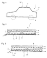
Fig. 1] Fig. 1 is a schematic cross-sectional view of a moving body in a first embodiment. - [
Fig. 2] Fig. 2 is a schematic cross-sectional view of a solar cell module in the first embodiment. - [
Fig. 3] Fig. 3 is a schematic cross-sectional view of a solar cell module in a modified example. - [
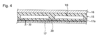
Fig. 4] Fig. 4 is a schematic cross-sectional view of a solar cell module in a second embodiment. - Examples of preferred embodiments to carry out the invention are described below. It is to be noted, however, that the following embodiments are mere examples. The invention is not in any way limited to the following embodiments.
- Moreover, in the drawings referred to in the embodiments and the like, components having substantially the same functions are denoted by the same reference numerals. In addition, the drawings referred to in the embodiments and the like are schematically illustrated. Accordingly, dimensional ratios and the like of objects depicted in the drawings may differ from actual dimensional ratios and the like of the objects. Such dimensional ratios and the like of the objects may also differ between the drawings. Therefore, the specific dimensional ratios and the like of the objects are to be determined in consideration of the following description.
- As illustrated in
Fig. 1 ,solar cell module 1 is used by being attached to movingbody 2. For example, movingbody 2 may be an automobile, an electric train, and the like. This embodiment explains an example in which movingbody 2 is constructed as an automobile. - Moving
body 2 includesvehicle body 2a andwheels 2b.Vehicle body 2a is mainly made of metal plates.Vehicle body 2a is provided with opening 2a1. Opening 2a1 may constitute a sun roof provided in the ceiling, for example.Solar cell module 1 is attached to opening 2a1. Here, opening 2a1 may be covered up withsolar cell module 1. Alternatively, opening 2a1 may be covered up with a window plate made of a material other than a metal, such as glass, andsolar cell module 1 may be attached to the window plate. - As illustrated in
Fig. 2 ,solar cell module 1 includessolar cells 10. Specifically,solar cell module 1 includessolar cells 10 that electrically connect to one another throughwiring members 20. However, the invention is not limited only to this configuration. For example, a solar cell module may include one solar cell. In the meantime, such a solar cell may be a back contact solar cell in which first and second electrodes are provided on one surface side, or may be a solar cell in which a first electrode is provided on one surface side while a second electrode is provided on another surface side. - First
protective member 16 is provided on one side ofsolar cells 10 while secondprotective member 17 is provided on another side thereof. Specifically, firstprotective member 16 is provided on an outer side ofsolar cells 10 when viewed from the vehicle, and secondprotective member 17 is provided on an inner side ofsolar cells 10 when viewed the vehicle.Sealant 15 is provided between firstprotective member 16 and secondprotective member 17.Solar cells 10 are sealed bysealant 15. Firstprotective member 16 can be made of a glass plate, a ceramic plate, a resin plate or the like.Sealant 15 can be made of a non-crosslinked resin such as ethylene vinyl acetate copolymer (EVA), a non-crosslinked resin such as polyolefin, and the like. - Second
protective member 17 adopts a three-layered structure, in whichmetal layer 17a is included betweenfirst resin layer 17b andsecond resin layer 17c.First resin layer 17b andsecond resin layer 17c can be each made of, for example, a fluorine-based resin film such as a polyvinyl fluoride film, a polyester film such as polyethylene terephthalate (PET) film, and the like.Metal layer 17a can be made of, for example, aluminum, an aluminum alloy, and the like.Metal layer 17a may be provided in a sheet fashion or provided in a mesh fashion. In other words,metal layer 17a may include openings.Metal layer 17a may be provided on the outside of a resin sheet. -
Metal layer 17a is connected to ground potential. Specifically, as illustrated inFig. 2 , secondprotective member 17 extends outward from other components at least at a portion on an end ofsolar cell module 1, and fitting 31 that penetrates secondprotective member 17 is attached to this extension portion. In other words, fitting 31 contacts and electrically connected tometal layer 17a. Fitting 31 connects tovehicle body 2a as illustrated inFig. 1 with anearth wire 30, which is schematically illustrated inFig. 2 . Thus,metal layer 17a is connected to the ground potential viavehicle body 2a andwheels 2b. Here,earth wire 30 may be connected directly tometal layer 17a without usingfitting 31. Fitting 31 may be connected directly tovehicle body 2a without usingearth wire 30. Alternatively, as illustrated inFig. 3 ,metal layer 17a extends outward from at least any offirst resin layer 17b andsecond resin layer 17c at least at a portion on an end ofsolar cell module 1, and is thus exposed from first and second resin layers 17b, 17c. Exposed portion 17a1 ofmetal layer 17a from first and second resin layers 17b, 17c may be connected tovehicle body 2a either directly or viaearth wire 30. - In general, devices including motors and electronic devices, which radiate electromagnetic waves, are provided inside the moving body. Accordingly, when the solar cell module is provided in the moving body, the solar cell module is exposed to the electromagnetic waves from the devices installed in the moving body. If the solar cell module is exposed to the electromagnetic waves, an output from the solar cell module may contain noise attributed to the electromagnetic waves, whereby its output characteristic may fluctuate.
- Here, in
solar cell module 1, secondprotective member 17 includesmetal layer 17a, andmetal layer 17a is connected to the ground potential. For this reason,metal layer 17a shields the electromagnetic waves from the inside of the vehicle, thereby inhibiting the electromagnetic waves radiated inside of the vehicle from reachingsolar cells 10. Thus, occurrence of the fluctuation in output characteristic attributed to the electromagnetic waves is suppressed, whereby a stable output characteristic is realized. - The first embodiment describes the example in which
metal layer 17a is provided inside secondprotective member 17. However, the location of the metal layer in the invention is not particularly limited as long as the metal layer is provided on the inner side of the solar cells when viewed from the vehicle (on the second protective member side). Nonetheless, the metal layer and each solar cell have to be electrically insulated from each other. - As illustrated in
Fig. 4 ,metal layer 17a may be provided betweensolar cells 10 and secondprotective member 17, and insidesealant 15 that is provided between firstprotective member 16 and secondprotective member 17. Here,sealant 15 is provided betweenmetal layer 17a andsolar cells 10. Sincesealant 15 is made of a resin,metal layer 17a and eachsolar cell 10 are insulated from each other. Alternatively,metal layer 17a may be provided at a boundary between secondprotective member 17 andsealant 15. An effect substantially the same as that of the first embodiment can also be obtained in these cases. -
- 1
- solar cell module
- 2
- moving body
- 10
- solar cell
- 15
- sealant
- 16
- first protective member
- 17
- second protective member
- 17a
- metal layer
- 17a1
- exposed portion
- 30
- earth wire
Claims (7)
- A solar cell module to installed in a moving body, comprising:a solar cell;a first protective member provided on an outer side of the solar cell when viewed from the moving body;a second protective member provided on an inner side of the solar cell when viewed from the moving body; anda metal layer provided inward of the solar cell when viewed from the moving body, whereinthe metal layer is insulated from the solar cell and is electrically connected to ground potential.
- The solar cell module according to claim 1, wherein the solar cell module is attached to an opening of the moving body.
- The solar cell module according to claim 1 or 2, wherein
the second protective member includes:a first resin layer facing the solar cell;a second resin layer facing inside of the moving body;and the metal layer provided between the first resin layer and the second resin layer. - The solar cell module according to any one of claims 1 to 3, further comprising:a sealant provided between the solar cell and the second protective member, whereinthe metal layer is provided inside the sealant.
- The solar cell module according to any one of claims 1 to 4, wherein the metal layer is connected to the ground potential by an earth wire connection to the moving body.
- The solar cell module according to claim 3, wherein
the metal layer includes an exposed portion exposed to at least one of the first resin layer and the second resin layer, and the metal layer is connected to the ground potential by connection of the exposed portion to the moving body. - The solar cell module according to any one of claims 1 to 6, wherein the moving body is an automobile.
Applications Claiming Priority (2)
| Application Number | Priority Date | Filing Date | Title |
|---|---|---|---|
| JP2012214511 | 2012-09-27 | ||
| PCT/JP2013/073634 WO2014050451A1 (en) | 2012-09-27 | 2013-09-03 | Solar cell module |
Publications (2)
| Publication Number | Publication Date |
|---|---|
| EP2903033A1 true EP2903033A1 (en) | 2015-08-05 |
| EP2903033A4 EP2903033A4 (en) | 2016-06-29 |
Family
ID=50387860
Family Applications (1)
| Application Number | Title | Priority Date | Filing Date |
|---|---|---|---|
| EP13841704.3A Withdrawn EP2903033A4 (en) | 2012-09-27 | 2013-09-03 | SOLAR CELL MODULE |
Country Status (5)
| Country | Link |
|---|---|
| US (1) | US20150194924A1 (en) |
| EP (1) | EP2903033A4 (en) |
| JP (1) | JPWO2014050451A1 (en) |
| CN (1) | CN104685636A (en) |
| WO (1) | WO2014050451A1 (en) |
Cited By (1)
| Publication number | Priority date | Publication date | Assignee | Title |
|---|---|---|---|---|
| WO2017220187A1 (en) * | 2016-06-21 | 2017-12-28 | Tulipps Solar International B.V. | A solar panel and a method for increasing safety and reliability of a solar panel |
Families Citing this family (2)
| Publication number | Priority date | Publication date | Assignee | Title |
|---|---|---|---|---|
| EP4395909A1 (en) * | 2021-09-02 | 2024-07-10 | Energy and Water Development Corp. | Self sufficient energy supplied system for generating atmospheric water and method to control the system |
| US20230173928A1 (en) * | 2021-12-03 | 2023-06-08 | George F. White, III | Photovoltaic Charging System for an Electric Vehicle Internal Battery |
Family Cites Families (12)
| Publication number | Priority date | Publication date | Assignee | Title |
|---|---|---|---|---|
| JPS60189272A (en) * | 1984-03-07 | 1985-09-26 | Sumitomo Electric Ind Ltd | solar cells |
| JPH02297976A (en) * | 1989-05-12 | 1990-12-10 | Toshiba Corp | Solar battery module |
| US5228925A (en) * | 1991-12-23 | 1993-07-20 | United Solar Systems Corporation | Photovoltaic window assembly |
| JP2006179626A (en) * | 2004-12-22 | 2006-07-06 | Showa Shell Sekiyu Kk | CIS-based thin-film solar cell module, method for producing the solar cell module, and separation method |
| JP4895745B2 (en) * | 2006-09-28 | 2012-03-14 | 昭和シェル石油株式会社 | CIS thin film solar cell module |
| US20080289681A1 (en) * | 2007-02-27 | 2008-11-27 | Adriani Paul M | Structures for low cost, reliable solar modules |
| US8748727B2 (en) * | 2008-01-18 | 2014-06-10 | Tenksolar, Inc. | Flat-plate photovoltaic module |
| JP2010219194A (en) * | 2009-03-16 | 2010-09-30 | Toyota Motor Corp | Solar cell module |
| US7960643B2 (en) * | 2009-05-12 | 2011-06-14 | Miasole | Isolated metallic flexible back sheet for solar module encapsulation |
| JP5494334B2 (en) | 2010-07-28 | 2014-05-14 | マツダ株式会社 | In-vehicle solar panel mounting structure |
| KR101262457B1 (en) * | 2010-10-05 | 2013-05-08 | 엘지이노텍 주식회사 | Solar cell apparatus |
| JP2012084587A (en) * | 2010-10-07 | 2012-04-26 | Lintec Corp | Protective sheet for solar cell module and solar cell module |
-
2013
- 2013-09-03 JP JP2014538318A patent/JPWO2014050451A1/en not_active Withdrawn
- 2013-09-03 WO PCT/JP2013/073634 patent/WO2014050451A1/en not_active Ceased
- 2013-09-03 CN CN201380050672.7A patent/CN104685636A/en active Pending
- 2013-09-03 EP EP13841704.3A patent/EP2903033A4/en not_active Withdrawn
-
2015
- 2015-03-23 US US14/665,012 patent/US20150194924A1/en not_active Abandoned
Cited By (2)
| Publication number | Priority date | Publication date | Assignee | Title |
|---|---|---|---|---|
| WO2017220187A1 (en) * | 2016-06-21 | 2017-12-28 | Tulipps Solar International B.V. | A solar panel and a method for increasing safety and reliability of a solar panel |
| NL1041939B1 (en) * | 2016-06-21 | 2018-01-04 | Petrus Paulus Carolus Maria Stassen Ing | A solar panel and method for increasing safety and reliability of a solar panel |
Also Published As
| Publication number | Publication date |
|---|---|
| CN104685636A (en) | 2015-06-03 |
| US20150194924A1 (en) | 2015-07-09 |
| EP2903033A4 (en) | 2016-06-29 |
| JPWO2014050451A1 (en) | 2016-08-22 |
| WO2014050451A1 (en) | 2014-04-03 |
Similar Documents
| Publication | Publication Date | Title |
|---|---|---|
| US9947818B2 (en) | Solar cell module | |
| EP2530737B1 (en) | Solar cell module | |
| US8607511B2 (en) | Solar cell module | |
| US20180175787A1 (en) | Flexible photovoltaic modules having junction box supporting flaps | |
| US20140373903A1 (en) | Solar cell module | |
| EP2819176A1 (en) | Flexible efficient solar cell panel | |
| JPWO2011013391A1 (en) | Solar cell module | |
| US20140174507A1 (en) | Apparatus for photovoltaic power generation | |
| US20110214716A1 (en) | Isolated metallic flexible back sheet for solar module encapsulation | |
| JP3204966U (en) | Flexible solar panel module | |
| US20130153004A1 (en) | Junction box with a support member for thin film photovoltaic devices and their methods of manufacture | |
| US20150194924A1 (en) | Solar cell module | |
| US20110155456A1 (en) | Junction box for solar panel | |
| US10630233B2 (en) | Solar cell module | |
| WO2012014922A1 (en) | Solar cell module | |
| US20130174887A1 (en) | Outer frame of solar cell module and solar cell module | |
| US10312394B2 (en) | Photovoltaic cell module | |
| WO2011093213A1 (en) | Terminal box for solar cell module, and solar cell module | |
| US20170012576A1 (en) | Interconnector and solar panel | |
| JP2012019023A (en) | Solar cell module assembly and moving body equipped with the same | |
| JP3200412U (en) | Flexible solar panel module and its fixing structure | |
| US9184326B2 (en) | Solar cell module | |
| US20150249426A1 (en) | Photovoltaic module junction box | |
| US9780244B2 (en) | Solar cell module | |
| KR20140053379A (en) | Solar module with connection socket, and method for producing same |
Legal Events
| Date | Code | Title | Description |
|---|---|---|---|
| PUAI | Public reference made under article 153(3) epc to a published international application that has entered the european phase |
Free format text: ORIGINAL CODE: 0009012 |
|
| 17P | Request for examination filed |
Effective date: 20150424 |
|
| AK | Designated contracting states |
Kind code of ref document: A1 Designated state(s): AL AT BE BG CH CY CZ DE DK EE ES FI FR GB GR HR HU IE IS IT LI LT LU LV MC MK MT NL NO PL PT RO RS SE SI SK SM TR |
|
| AX | Request for extension of the european patent |
Extension state: BA ME |
|
| RAP1 | Party data changed (applicant data changed or rights of an application transferred) |
Owner name: PANASONIC INTELLECTUAL PROPERTY MANAGEMENT CO., LT |
|
| DAX | Request for extension of the european patent (deleted) | ||
| RA4 | Supplementary search report drawn up and despatched (corrected) |
Effective date: 20160531 |
|
| RIC1 | Information provided on ipc code assigned before grant |
Ipc: B60L 8/00 20060101ALI20160524BHEP Ipc: H02S 10/40 20140101ALI20160524BHEP Ipc: H01L 31/048 20060101AFI20160524BHEP Ipc: B60K 16/00 20060101ALI20160524BHEP Ipc: H01L 31/02 20060101ALI20160524BHEP |
|
| STAA | Information on the status of an ep patent application or granted ep patent |
Free format text: STATUS: THE APPLICATION HAS BEEN WITHDRAWN |
|
| 18W | Application withdrawn |
Effective date: 20160809 |