EP2902870A2 - Display device and method of driving the same - Google Patents
Display device and method of driving the same Download PDFInfo
- Publication number
- EP2902870A2 EP2902870A2 EP15153582.0A EP15153582A EP2902870A2 EP 2902870 A2 EP2902870 A2 EP 2902870A2 EP 15153582 A EP15153582 A EP 15153582A EP 2902870 A2 EP2902870 A2 EP 2902870A2
- Authority
- EP
- European Patent Office
- Prior art keywords
- display
- unit
- viewing
- display device
- control unit
- Prior art date
- Legal status (The legal status is an assumption and is not a legal conclusion. Google has not performed a legal analysis and makes no representation as to the accuracy of the status listed.)
- Granted
Links
Images








Classifications
-
- G—PHYSICS
- G09—EDUCATION; CRYPTOGRAPHY; DISPLAY; ADVERTISING; SEALS
- G09G—ARRANGEMENTS OR CIRCUITS FOR CONTROL OF INDICATING DEVICES USING STATIC MEANS TO PRESENT VARIABLE INFORMATION
- G09G3/00—Control arrangements or circuits, of interest only in connection with visual indicators other than cathode-ray tubes
- G09G3/03—Control arrangements or circuits, of interest only in connection with visual indicators other than cathode-ray tubes specially adapted for displays having non-planar surfaces, e.g. curved displays
- G09G3/035—Control arrangements or circuits, of interest only in connection with visual indicators other than cathode-ray tubes specially adapted for displays having non-planar surfaces, e.g. curved displays for flexible display surfaces
-
- G—PHYSICS
- G06—COMPUTING OR CALCULATING; COUNTING
- G06F—ELECTRIC DIGITAL DATA PROCESSING
- G06F1/00—Details not covered by groups G06F3/00 - G06F13/00 and G06F21/00
- G06F1/16—Constructional details or arrangements
- G06F1/1613—Constructional details or arrangements for portable computers
- G06F1/1615—Constructional details or arrangements for portable computers with several enclosures having relative motions, each enclosure supporting at least one I/O or computing function
- G06F1/1616—Constructional details or arrangements for portable computers with several enclosures having relative motions, each enclosure supporting at least one I/O or computing function with folding flat displays, e.g. laptop computers or notebooks having a clamshell configuration, with body parts pivoting to an open position around an axis parallel to the plane they define in closed position
-
- G—PHYSICS
- G06—COMPUTING OR CALCULATING; COUNTING
- G06F—ELECTRIC DIGITAL DATA PROCESSING
- G06F1/00—Details not covered by groups G06F3/00 - G06F13/00 and G06F21/00
- G06F1/16—Constructional details or arrangements
- G06F1/1613—Constructional details or arrangements for portable computers
- G06F1/1633—Constructional details or arrangements of portable computers not specific to the type of enclosures covered by groups G06F1/1615 - G06F1/1626
- G06F1/1637—Details related to the display arrangement, including those related to the mounting of the display in the housing
- G06F1/1641—Details related to the display arrangement, including those related to the mounting of the display in the housing the display being formed by a plurality of foldable display components
-
- G—PHYSICS
- G06—COMPUTING OR CALCULATING; COUNTING
- G06F—ELECTRIC DIGITAL DATA PROCESSING
- G06F1/00—Details not covered by groups G06F3/00 - G06F13/00 and G06F21/00
- G06F1/16—Constructional details or arrangements
- G06F1/1613—Constructional details or arrangements for portable computers
- G06F1/1633—Constructional details or arrangements of portable computers not specific to the type of enclosures covered by groups G06F1/1615 - G06F1/1626
- G06F1/1637—Details related to the display arrangement, including those related to the mounting of the display in the housing
- G06F1/1647—Details related to the display arrangement, including those related to the mounting of the display in the housing including at least an additional display
-
- G—PHYSICS
- G06—COMPUTING OR CALCULATING; COUNTING
- G06F—ELECTRIC DIGITAL DATA PROCESSING
- G06F1/00—Details not covered by groups G06F3/00 - G06F13/00 and G06F21/00
- G06F1/16—Constructional details or arrangements
- G06F1/1613—Constructional details or arrangements for portable computers
- G06F1/1633—Constructional details or arrangements of portable computers not specific to the type of enclosures covered by groups G06F1/1615 - G06F1/1626
- G06F1/1675—Miscellaneous details related to the relative movement between the different enclosures or enclosure parts
- G06F1/1677—Miscellaneous details related to the relative movement between the different enclosures or enclosure parts for detecting open or closed state or particular intermediate positions assumed by movable parts of the enclosure, e.g. detection of display lid position with respect to main body in a laptop, detection of opening of the cover of battery compartment
-
- G—PHYSICS
- G06—COMPUTING OR CALCULATING; COUNTING
- G06F—ELECTRIC DIGITAL DATA PROCESSING
- G06F3/00—Input arrangements for transferring data to be processed into a form capable of being handled by the computer; Output arrangements for transferring data from processing unit to output unit, e.g. interface arrangements
- G06F3/002—Specific input/output arrangements not covered by G06F3/01 - G06F3/16
- G06F3/005—Input arrangements through a video camera
-
- G—PHYSICS
- G06—COMPUTING OR CALCULATING; COUNTING
- G06F—ELECTRIC DIGITAL DATA PROCESSING
- G06F3/00—Input arrangements for transferring data to be processed into a form capable of being handled by the computer; Output arrangements for transferring data from processing unit to output unit, e.g. interface arrangements
- G06F3/01—Input arrangements or combined input and output arrangements for interaction between user and computer
- G06F3/011—Arrangements for interaction with the human body, e.g. for user immersion in virtual reality
-
- G—PHYSICS
- G06—COMPUTING OR CALCULATING; COUNTING
- G06F—ELECTRIC DIGITAL DATA PROCESSING
- G06F3/00—Input arrangements for transferring data to be processed into a form capable of being handled by the computer; Output arrangements for transferring data from processing unit to output unit, e.g. interface arrangements
- G06F3/01—Input arrangements or combined input and output arrangements for interaction between user and computer
- G06F3/03—Arrangements for converting the position or the displacement of a member into a coded form
- G06F3/0304—Detection arrangements using opto-electronic means
-
- G—PHYSICS
- G06—COMPUTING OR CALCULATING; COUNTING
- G06T—IMAGE DATA PROCESSING OR GENERATION, IN GENERAL
- G06T3/00—Geometric image transformations in the plane of the image
- G06T3/40—Scaling of whole images or parts thereof, e.g. expanding or contracting
-
- G—PHYSICS
- G09—EDUCATION; CRYPTOGRAPHY; DISPLAY; ADVERTISING; SEALS
- G09G—ARRANGEMENTS OR CIRCUITS FOR CONTROL OF INDICATING DEVICES USING STATIC MEANS TO PRESENT VARIABLE INFORMATION
- G09G3/00—Control arrangements or circuits, of interest only in connection with visual indicators other than cathode-ray tubes
- G09G3/20—Control arrangements or circuits, of interest only in connection with visual indicators other than cathode-ray tubes for presentation of an assembly of a number of characters, e.g. a page, by composing the assembly by combination of individual elements arranged in a matrix no fixed position being assigned to or needed to be assigned to the individual characters or partial characters
- G09G3/2092—Details of a display terminals using a flat panel, the details relating to the control arrangement of the display terminal and to the interfaces thereto
-
- G—PHYSICS
- G06—COMPUTING OR CALCULATING; COUNTING
- G06T—IMAGE DATA PROCESSING OR GENERATION, IN GENERAL
- G06T2215/00—Indexing scheme for image rendering
- G06T2215/16—Using real world measurements to influence rendering
Definitions
- Embodiments of the invention relate to a display device and a method of driving the display device, and in particular, to a shape-changeable display device and a method of driving the shape-changeable display device.
- a display panel is widely used for electronic devices with image-displaying function, such as smartphones, digital cameras, laptop computers, navigation systems and television sets, for example.
- Various types of flat display panel such as a liquid crystal display panel, an organic light emitting display panel, a plasma display panel and an electrophoresis display panel, for example, are being widely used as the display panel of an electronic device by virtue of thin and lightweight properties thereof.
- the foldable and flexible display devices are being studied. Due to features thereof such as thin, lightweight and unbroken properties, for example, the foldable and flexible display devices may be used for various industry fields, including information technology ("IT”), clothing, and paper-like media industries.
- IT information technology
- clothing clothing, and paper-like media industries.
- Embodiments of the invention seek to provide a display device configured to compensate image distortion, which may occur when the display device is deformed, and thereby to have improved display quality.
- a display device includes a display unit which displays an image in a bent state and including a plurality of display surfaces divided from each other by a bending position thereof, a bend-measuring unit including a sensor which measures a bending value of the display unit, a viewpoint-monitoring unit including a sensor which measures a viewing position of a viewer, where the viewpoint-monitoring unit outputs position information based on the measured viewing position of the viewer, a control unit which compensates image data to be displayed on each of the display surfaces, based on the bending value and the position information, and a driving unit which drives the display unit using the compensated image data.
- a method of driving a display device includes measuring a bending value of a display unit of the display device, where the display unit displays an image in a bent state and comprising a plurality of display surfaces divided from each other by a bending position thereof, measuring a viewing position of a viewer to obtain position information based on the viewing position, compensating image data to be displayed on each of the display surfaces, based on the bending value and the position information, and driving the display unit using the compensated image data.
- spatially relative terms such as “beneath,” “below,” “lower,” “above,” “upper” and the like, may be used herein for ease of description to describe one element or feature's relationship to another element(s) or feature(s) as illustrated in the figures. It will be understood that the spatially relative terms are intended to encompass different orientations of the device in use or operation in addition to the orientation depicted in the figures. For example, if the device in the figures is turned over, elements described as “below” or “beneath” other elements or features would then be oriented “above” the other elements or features. Thus, the term “below” can encompass both an orientation of above and below. The device may be otherwise oriented (rotated 90 degrees or at other orientations) and the spatially relative descriptors used herein interpreted accordingly.
- relative terms such as “lower” or “bottom” and “upper” or “top,” may be used herein to describe one element's relationship to another element as illustrated in the Figures. It will be understood that relative terms are intended to encompass different orientations of the device in addition to the orientation depicted in the Figures. For example, if the device in one of the figures is turned over, elements described as being on the “lower” side of other elements would then be oriented on “upper” sides of the other elements. The term “lower,” can therefore, encompasses both an orientation of “lower” and “upper,” depending on the particular orientation of the figure.
- Embodiments of the invention are described herein with reference to cross section illustrations that are schematic illustrations of idealized embodiments. As such, variations from the shapes of the illustrations as a result, for example, of manufacturing techniques and/or tolerances, are to be expected. Thus, embodiments described herein should not be construed as limited to the particular shapes of regions as illustrated herein but are to include deviations in shapes that result, for example, from manufacturing. For example, a region illustrated or described as flat may, typically, have rough and/or nonlinear features. Moreover, sharp angles that are illustrated may be rounded. Thus, the regions illustrated in the figures are schematic in nature and their shapes are not intended to illustrate the precise shape of a region and are not intended to limit the scope of the present claims.
- FIG. 1 is a block diagram schematically illustrating an embodiment of a display device according to the invention.
- an embodiment of a display device 700 may include a control unit 100, a bend-measuring unit 200, a viewpoint-monitoring unit 300, a storing unit 400, a driving unit 500 and a display unit 600.
- the display unit 600 may be configured to display information on an operation state, figures, letters, characters, moving images, still images, and so forth.
- the display unit 600 may include a foldable display unit, which is configured to be folded along a folding line, or a flexible display unit including a flexible material (e.g., plastic) and thereby being bendable like paper or a plastic film.
- a foldable display unit which is configured to be folded along a folding line
- a flexible display unit including a flexible material (e.g., plastic) and thereby being bendable like paper or a plastic film.
- the display unit 600 may be configured to display images in a bent state and include at least two display surfaces that are divided from each other by a bending position.
- the display unit 600 may include N display surfaces, where N is an integer of 2 or greater.
- the display unit 600 may be configured in such a way that images therefrom may be seen to be similar to an image (i.e., a flat image) displayed on an un-folded display unit, even when the display unit 600 is in a partially-folded or curved state.
- the display device 700 may include the bend-measuring unit 200, the viewpoint-monitoring unit 300 and the storing unit 400, as described above, and the control unit 100 may be configured to compensate image data, which will be provided to the display unit 600, based on information provided from the bend-measuring unit 200, the viewpoint-monitoring unit 300 and the storing unit 400.
- the bend-measuring unit 200 may include a bending-measurement sensor that measures deformation in shape of the display unit 600.
- the bending-measurement sensor may be a gyro sensor or a strain sensor, for example.
- the gyro sensor is used as the bending-measurement sensor will hereinafter be described in detail.
- the bend-measuring unit 200 may measure a bending value of the display unit 600 using the gyro sensor.
- the viewpoint-monitoring unit 300 may include a position-monitoring sensor that is configured to measure a viewing position of a viewer of the display unit 600.
- a position-monitoring sensor that is configured to measure a viewing position of a viewer of the display unit 600.
- an optical sensor or a motion-detecting sensor may be used as the position-monitoring sensor.
- control unit 100 may calculate a folding angle between two adjacent display surfaces from the bending value provided from the bend-measuring unit 200. In such an embodiment, the control unit 100 may execute a calculation operation for obtaining a viewing angle between respective display surfaces and the viewing position of the viewer, based on the position information of the viewer measured by the position-monitoring sensor.
- control unit 100 may compensate original image data to be provided to the display surfaces based on the folding angle and the viewing angle.
- the control unit 100 may refer to the storing unit 400, in which a compensation table is stored, for such a process of image compensation.
- the compensation table may include compensation values (e.g., weights for a scaling process) corresponding to the folding and viewing angles.
- the image data compensated by the control unit 100 may be transferred to the driving unit 500.
- the driving unit 500 may generate data voltages for driving the display unit 600, based on the transferred image data, and then, be provided to the display unit 600.
- image data distorted by the bending of the display device may be compensated based on the folding and viewing angles, and thus, the viewer may be allow to perceive the compensated images to be similar to a flat image, within a pre-set range such that display quality and visibility of the display device 700 may be substantially improved.
- FIG. 2A is a perspective view illustrating an embodiment of a foldable display unit in an un-folded state
- FIG. 2B is a perspective view illustrating an embodiment of a foldable display unit in a folded state.
- an embodiment of the display unit 600 may include a foldable display unit 610.
- the foldable display unit 610 may include a first display unit 620 with a first display surface 621 and a second display unit 630 with a second display surface 631.
- a folding angle between the first and second display surfaces 621 and 631 may be substantially 180°.
- the foldable display unit 610 may be operation in a double screen mode; for example, images may be displayed on the first and second display surfaces 621 and 631.
- the foldable display unit 610 When the foldable display unit 610 is completely folded as shown in FIG. 2B or the folding angle between the first and second display surface 621 and 631 is smaller than a pre-set reference folding angle, the foldable display unit 610 may be turned off.
- the foldable display unit 610 may be folded in such a way that the first and second display surfaces 621 and 631 face each other (i.e., in an in-folded manner) or opposite surfaces thereof face each other (i.e., in an out-folded manner).
- the first display unit 620 may further include a first peripheral region 622 provided around the first display surface 621, and the second display unit 630 may further include a second peripheral region 632 provided around the second display surface 631.
- a first gyro sensor 651 and a first position-monitoring sensor 661 may be provided in the first peripheral region 622, and a second gyro sensor 652 and a second position-monitoring sensor 662 may be provided in the second peripheral region 632.
- each of a single first gyro sensor 651 and a single second gyro sensor 652 may be provided in a corresponding one of the first and second peripheral region 622 and 632.
- a plurality of the first gyro sensors 651 and/or a plurality of the second gyro sensors 652 may be two-dimensionally arranged and spaced apart from each other on a corresponding one of the first and second display unit 620 and 630.
- each of a single first position-monitoring sensors 661 and a single second position-monitoring sensor 662 may be provided in a corresponding one of the first and second peripheral regions 622 and 632.
- a plurality of the first position-monitoring sensor 661 and/or a plurality of the second position-monitoring sensor 662 may be two-dimensionally arranged and spaced apart from each other on a corresponding one of the first and second display unit 620 and 630.
- the foldable display unit 610 may further include a jointing unit (not shown) that connects the first and second display units 620 and 630 to each other.
- the jointing unit may be configured to connect the first and second display units 620 and 630 to each other in a hinge-like manner.
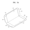
- FIG. 3A is a perspective view illustrating an embodiment of a foldable display unit in a partially-folded state
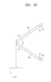
- FIG. 3B is a side view illustrating an embodiment of a foldable display unit in a partially-folded state.
- the first and second display units 620 and 630 may be folded based on an axis of a hinge in such a way that the first and second display surfaces 621 and 631 face each other.
- first direction D1 a direction parallel to a gravity direction
- second direction D2 a direction substantially perpendicular to the first direction D 1
- first and second display units 620 and 630 when the first and second display units 620 and 630 are in an un-folded state, the first and second display units 620 and 630 may be substantially parallel to the gravity direction. In such an unfolded state, both of first and second bending angles ⁇ a and ⁇ b measured by the first and second gyro sensors 651 and 652, respectively, may be about 0°.
- the first bending angle ⁇ a between the first display unit 620 and the gravity direction may be a finite value greater than about 0°
- the second bending angle ⁇ b between the second display unit 630 and the gravity direction may be a finite value greater than about 0°
- the control unit 100 may compensate image data, which will be provided to the display unit 600, based on the folding angle ⁇ .
- the control unit 100 may adjust a scale of an image displayed on each of the first and second display surfaces 621 and 631 based on the folding angle ⁇ , and may perform the scale adjustment to allow the resulting image to be displayed with substantially the same size as a flat image, even when the foldable display unit 610 is partially folded.
- FIGS. 4A through 4C are schematic diagrams illustrating images displayed by an embodiment of a foldable display unit, based on a folding angle.
- FIG. 4A shows an embodiment of the foldable display unit 610 that displays a letter 'A' with a first size at the folding angle ⁇ of about 180°.
- the letter 'A' displayed on the foldable display unit 610 may be controlled or scaled to be substantially the same size as the first size. This scaling may be achieved by compensating image data to be provided to the first and second display surface 621 and 631 based on the folding angles ⁇ .
- deformation of the foldable display unit 610 may be monitored in real-time to adjust a scale of an image to be displayed on the first and second display surfaces 621 and 631, such that the image is effectively prevented from being distorted, thereby improving a display quality of the display device.
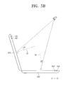
- FIGS. 5A through 5C are schematic diagrams illustrating a change in viewing angles of two display surfaces of an embodiment of a foldable display, based on a viewing position of a viewer.
- a line normal to the first display surface 621 will be referred to as a first virtual line V1
- a line normal to the second display surface 631 will be referred to a second virtual line V2.
- a first position information sensor 661 may be provided in the first display unit 620 to track a position of the viewer, and a second position information sensor 662 may be provided in the second display unit 630 to track the position of the viewer. Information on the position of the viewer may be obtained by the first and second position information sensors 661 and 662 and then be transferred to the control unit 100.
- the viewer position information may be transferred from the first and second position information sensors 661 and 662 to the control unit 100, and the bending information may be transferred from the first and second gyro sensors 651 and 652 to the control unit 100.
- the control unit 100 may calculate the first and second viewing angles ⁇ 1 and 02 from the first and second virtual lines V1 and V2, respectively, to the viewing position of the viewer.
- the first and second viewing angles ⁇ 1 and ⁇ 2 may be substantially identical to each other.
- the compensation of the image data may be performed based on the first viewing angle ⁇ 1.
- images to be displayed on the first and second display units 620 and 630 may be scaled up or down substantially in the same manner.
- the second viewing angle ⁇ 2 may be less than the first viewing angle ⁇ 1.
- the viewer may stare more directly at the second display unit 630 than at the first display unit 620. Accordingly, for the viewer, the image on the first display unit 620 appears to be more deformed than the image on the second display unit 630.
- the compensation of the image data in the control unit 100 may be performed in such a way that the sizes of the images to be displayed on the display surfaces are adjusted with different scale factors.
- the image on the first display unit 620 may be more distorted than the image on the second display unit 630.
- a scale of an image to be displayed on the second display unit 630 may be adjusted with a first weight
- a scale of an image to be displayed on the first display unit 620 may be adjusted with a second weight that is different from (e.g., greater than) the first weight.
- the viewer may stare more directly at the first display unit 620 than at the second display unit 630. Accordingly, for the viewer, the image displayed on the second display unit 630 appears to be more deformed than the image on the first display unit 620.
- the compensation in the control unit 100 may be performed to apply different scaling conditions to the image data, which will be displayed on the first and second display units 620 and 630, respectively.
- the image on the second display unit 630 may be more distorted than the image on the first display unit 620.
- a scale of the image on the second display unit 630 may be adjusted with a third weight
- a scale of the image on the first display unit 620 may be adjusted with a fourth weight that is different from (e.g., smaller than) the third weight.
- the first to fourth weights may vary depending on the folding angle ⁇ . In one embodiment, for example, the first to fourth weights may be increased as the folding angle ⁇ is decreased to enlarge the size of the image through the scaling.
- an xy-plane may be defined as one of planes that are parallel to the second display surface 631.
- the control unit 100 may calculate spherical coordinates of the viewing position of the viewer based on information transferred from the second position-monitoring sensor 662. In one embodiment, for example, in a first spherical coordinate system with an origin located on the second display unit 630, the control unit 100 may calculate a polar angle ⁇ 2 and an azimuth angle ⁇ 1 to specify a viewing direction of the viewer.
- the image on the first display surface 621 may be compensated using information on the viewing position of the viewer, which may be given by polar and azimuth angles in another spherical coordinate system or a second spherical coordinate system, whose origin is located on the first display unit 620.
- the control unit 100 may execute calculation to obtain the polar and azimuth angles in the second spherical coordinate system from data, which have been measured by the first position-monitoring sensor 661.
- the control unit 100 may perform the compensation of the image data to be displayed on the first display unit 620 based on the polar and azimuth angles in the second spherical coordinate system.
- the control unit 100 may be configured to compensate the image data, which will be displayed on the first and second display surfaces 621 and 631, based on not only the folding angle ⁇ between the first and second display units 620 and 630 but also the viewing direction of the viewer (e.g., the first and second viewing angles ⁇ 1 and 02).
- the control unit 100 may be configured to allow the viewer to perceive an image on the display device 700 as a flat image or one similar thereto, within a pre-set range. Accordingly, display quality and visibility of the display device 700 may be improved.
- FIGS. 7A through 7D are diagrams illustrating an embodiment of a driving operation of a control unit, according to various viewing angles.
- the control unit 100 may set a reference angle ⁇ r to provide an angle range allowing the viewer to see an image without any distortion.
- the control unit 100 may calculate the first and second viewing angles ⁇ 1 and ⁇ 2 of the viewer, based on measurement data transferred from the first and second position-monitoring sensors 661 and 662.
- the first and second viewing angles ⁇ 1 and ⁇ 2 may be angles from the first and second virtual lines V1 and V2, respectively, to the viewer.
- the control unit 100 may compare the first and second viewing angles ⁇ 1 and ⁇ 2 with the reference angle ⁇ r. When both of the first and second viewing angles ⁇ 1 and ⁇ 2 are smaller than the reference angle ⁇ r, the control unit 100 may decide that the viewer is located at a position, allowing the viewer to view normally images on the first and second display units 620 and 630. In such an embodiment, the control unit 100 may perform an operation for compensating image data to be displayed on the first and second display units 620 and 630, based on the first and second viewing angles ⁇ 1 and ⁇ 2.
- the control unit 100 may decide that the viewer is located at a position, at which an image on the first display unit 620, but not the second display unit 630, can be seen by the viewer. In this case, the control unit 100 may turn off the second display unit 630 and turn on only the first display unit 620, and the control unit 100 may perform an operation for compensating image data to be displayed on the first display unit 620, based on the first viewing angle ⁇ 1.
- the control unit 100 may decide that the viewer is located at a position, at which an image on the second display unit 630, but not the first display unit 620, can be seen by the viewer. In this case, the control unit 100 may turn off the first display unit 620 and turn on only the second display unit 630, and the control unit 100 may perform an operation for compensating image data to be displayed on the second display unit 630, based on the second viewing angle ⁇ 2.
- the control unit 100 may decide that the viewer is located at a position, at which none of images on the first and second display units 620 and 630 can be seen by the viewer. In this case, the control unit 100 may turn off the first and second display units 620 and 630.
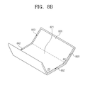
- FIGS. 8A through 8C are perspective views illustrating an embodiment of a three-stage foldable display unit according to the invention.
- an embodiment of a three-stage foldable display unit 800 may include first, second and third display surfaces 811, 821 and 831, which may be sequentially arranged in, for example, a first direction D1.
- a first gyro sensor 841 and a first position-monitoring sensor 851 may be provided at both side edges 812 and 813 of the first display surface 811 (for example, in second and third directions D2 and D3).
- a second gyro sensor 842 and a second position-monitoring sensor 852 may be provided at both side edges 822 and 823 of the second display surface 821, and a third gyro sensor 843 and a third position-monitoring sensor 853 may be provided at both side edges 832 and 833 of the third display surface 831.
- the numbers and positions of the first to third gyro sensors 841, 842, and 843 and the first to third position-monitoring sensors 851, 852 and 853 in embodiments of the invention are not limited to those of the embodiment illustrated in FIG. 8A .
- the control unit 100 may calculate a first folding angle ⁇ 3 between the first display surface 811 and the second display surface 821 using measurement data obtained from the first and second gyro sensor 841 and 842. In such an embodiment, the control unit 100 may calculate a second folding angle ⁇ 4 between the second display surface 821 and the third display surface 831 using measurement data obtained from the second and third gyro sensor 842 and 843.
- the control unit 100 may compare the first and second folding angles ⁇ 3 and 04 with a pre-set reference folding angle. When the first and second folding angles ⁇ 3 and ⁇ 4 are smaller than the reference folding angle, all of the first to third display surfaces 811, 821 and 831 may be turned off. In one embodiment, for example, as shown in FIG. 8C , when the three-stage foldable display unit 800 is folded to form a three-folded structure, all of the first to third display surfaces 811, 821 and 831 may be turned off.
- the first and second display surfaces 811 and 821 when the first folding angle ⁇ 3 between the first and second display surfaces 811 and 821 are smaller than the reference folding angle and the second folding angle ⁇ 4 is greater than the reference folding angle, the first and second display surfaces 811 and 821 may be turned off and the third display surface 831 may be turned on. In this case, the compensation of the image data may be performed based on measurement data obtained from the third position-monitoring sensor 853.
- the second and third display surfaces 821 and 831 may be turned off and the first display surface 811 may be turned on.
- the compensation of the image data may be performed based on measurement data obtained from the first position-monitoring sensor 851.
- the first to third display surfaces 811, 821 and 831 may be turned on.
- the compensation of the image data to be displayed on the first to third display surfaces 811, 821 and 831, respectively, may be performed based on measurement data obtained from the first to third position-monitoring sensors 851, 852 and 853.
- the control unit 100 may calculate a first viewing angle (not shown) between the first display surface 811 and the viewer and may compensate image data to be provided to the first display surface 811, based on the first viewing angle.
- the control unit 100 may calculate second and third viewing angles (not shown) between the second and third display surfaces 821 and 831 and the viewer, and then, compensate image data to be provided to the second and third display surfaces 821 and 831, respectively, based on the second and third viewing angles.
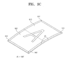
- FIGS. 9A through 9C are perspective views illustrating an embodiment of a flexible display unit according to the invention.
- a flexible display unit may be divided into first and second display surfaces 910 and 920, which are defined based on a reference line.
- the first and second display surface 910 and 920 may be connected to each other on the reference line, thereby forming a single continuous screen.
- a peripheral region may be provided around the first and second display surfaces 910 and 920, and first and second gyro sensors 931 and 932 and first and second position-monitoring sensors 941 and 942 may be provided on the peripheral region.
- the first gyro sensor 931 and the first position-monitoring sensor 941 may be disposed on a first peripheral region 911 positioned around the first display surface 910, and the second gyro sensor 932 and the second position-monitoring sensor 942 may be disposed on a second peripheral region 922 positioned around the second display surface 920.
- the numbers and positions of the gyro and position-monitoring sensors in embodiments of the invention are not limited to those of the embodiment illustrated in FIG. 9A .
- control unit 100 may calculate a folding angle ⁇ between the first and second display surfaces 910 and 920 using measurement data obtained from the first and second gyro sensors 931 and 932.
- control unit 100 may decide that the first and second display surfaces 910 and 920 are folded to face each other (i.e., in an in-folded state).
- the control unit 100 may decide that the first and second display surfaces 910 and 920 are folded in such a way that opposite surfaces thereof face each other (i.e., in an out-folded state).
- the storing unit 400 may further include a compensation table, in which weights for the in-folded state and weights for the out-folded state are separately stored.
- first and second positions P1 and P2 may represent center points of the first and second display surfaces 910 and 920, respectively, and first and second virtual lines V1 and V2 may represent lines that are normal to the tangential surfaces of the first and second positions P1 and P2, respectively.
- control unit 100 may calculate first and second viewing angles ⁇ 1 and ⁇ 2 between the viewer and the first and second virtual lines V1 and V2, based on measurement data obtained from the first and second position-monitoring sensors 941 and 942.
- control unit 100 may perform an operation of compensating image data to be displayed on each of the first and second display surfaces 910 and 920, based on the first and second viewing angles ⁇ 1 and ⁇ 2.
- Such a compensating operation may be performed in a similar manner to that of the embodiments described above with reference to FIGS. 1 through 8C , and any repetitive detailed description thereof will be omitted.
- the image data distorted by the bending of the display device may be compensated based on the folding and viewing angles, and thus, the viewer is allowed to perceive the compensated images to be similar to a flat image, within a pre-set range, such that display quality and visibility of the display device are substantially improved.
Landscapes
- Engineering & Computer Science (AREA)
- Theoretical Computer Science (AREA)
- Physics & Mathematics (AREA)
- Computer Hardware Design (AREA)
- General Physics & Mathematics (AREA)
- General Engineering & Computer Science (AREA)
- Human Computer Interaction (AREA)
- Mathematical Physics (AREA)
- Multimedia (AREA)
- Controls And Circuits For Display Device (AREA)
- Devices For Indicating Variable Information By Combining Individual Elements (AREA)
- Control Of Indicators Other Than Cathode Ray Tubes (AREA)
- Liquid Crystal (AREA)
- Control Of El Displays (AREA)
Abstract
Description
- Embodiments of the invention relate to a display device and a method of driving the display device, and in particular, to a shape-changeable display device and a method of driving the shape-changeable display device.
- A display panel is widely used for electronic devices with image-displaying function, such as smartphones, digital cameras, laptop computers, navigation systems and television sets, for example.
- Various types of flat display panel, such as a liquid crystal display panel, an organic light emitting display panel, a plasma display panel and an electrophoresis display panel, for example, are being widely used as the display panel of an electronic device by virtue of thin and lightweight properties thereof.
- Recently, foldable or flexible display devices are being studied. Due to features thereof such as thin, lightweight and unbroken properties, for example, the foldable and flexible display devices may be used for various industry fields, including information technology ("IT"), clothing, and paper-like media industries.
- Embodiments of the invention seek to provide a display device configured to compensate image distortion, which may occur when the display device is deformed, and thereby to have improved display quality.
- Other embodiments of the invention seek to provide a method of driving the display device.
- According to embodiments of the invention, a display device includes a display unit which displays an image in a bent state and including a plurality of display surfaces divided from each other by a bending position thereof, a bend-measuring unit including a sensor which measures a bending value of the display unit, a viewpoint-monitoring unit including a sensor which measures a viewing position of a viewer, where the viewpoint-monitoring unit outputs position information based on the measured viewing position of the viewer, a control unit which compensates image data to be displayed on each of the display surfaces, based on the bending value and the position information, and a driving unit which drives the display unit using the compensated image data.
- According to other embodiments of the invention, a method of driving a display device includes measuring a bending value of a display unit of the display device, where the display unit displays an image in a bent state and comprising a plurality of display surfaces divided from each other by a bending position thereof, measuring a viewing position of a viewer to obtain position information based on the viewing position, compensating image data to be displayed on each of the display surfaces, based on the bending value and the position information, and driving the display unit using the compensated image data.
- At least some of the above and other features of the invention are set-out in the claims.
- The above and other feature of the invention will be made more apparent by describing in further detail embodiments thereof with reference to the accompanying drawings, in which:
-
FIG. 1 is a block diagram schematically illustrating an embodiment of a display device according to the invention; -
FIG. 2A is a perspective view illustrating an embodiment of a foldable display unit in an un-folded state; -
FIG. 2B is a perspective view illustrating an embodiment of a foldable display unit in a folded state; -
FIG. 3A is a perspective view illustrating an embodiment of a foldable display unit in a partially-folded state; -
FIG. 3B is a side view illustrating an embodiment of a foldable display unit in a partially-folded state; -
FIGS. 4A through 4C are schematic diagrams illustrating images displayed by an embodiment of a foldable display unit, based on a folding angle; -
FIGS. 5A through 5C are schematic diagrams illustrating a change in viewing angles of two display surfaces of an embodiment of a foldable display, based on a viewing position of a viewer; -
FIG. 6 is a diagram illustrating a viewing position of a viewer in a spherical coordinate system, where an origin of the viewing position is located on a second display unit; -
FIGS. 7A through 7D are diagrams illustrating an embodiment of a driving operation of a control unit according to various viewing angles; -
FIGS. 8A through 8C are perspective views illustrating an embodiment of a three-stage foldable display unit according to the invention; and -
FIGS. 9A through 9C are perspective views illustrating an embodiment of a flexible display unit according to the invention; - The invention will now be described more fully hereinafter with reference to the accompanying drawings, in which various embodiments thereof are shown. This invention may, however, be embodied in many different forms, and should not be construed as limited to the embodiments set forth herein. Rather, these embodiments are provided so that this disclosure will be thorough, and will convey the scope of the invention to those skilled in the art. Like reference numerals refer to like elements throughout.
- It will be understood that when an element is referred to as being "on," "connected" or "coupled" to another element, it can be directly connected or coupled to the other element or intervening elements may be present. In contrast, when an element is referred to as being "directly on," "directly connected" or "directly coupled" to another element, there are no intervening elements present.
- It will be understood that, although the terms "first," "second," "third" etc. may be used herein to describe various elements, components, regions, layers and/or sections, these elements, components, regions, layers and/or sections should not be limited by these terms. These terms are only used to distinguish one element, component, region, layer or section from another element, component, region, layer or section. Thus, "a first element," "component," "region," "layer" or "section" discussed below could be termed a second element, component, region, layer or section without departing from the teachings herein.
- Spatially relative terms, such as "beneath," "below," "lower," "above," "upper" and the like, may be used herein for ease of description to describe one element or feature's relationship to another element(s) or feature(s) as illustrated in the figures. It will be understood that the spatially relative terms are intended to encompass different orientations of the device in use or operation in addition to the orientation depicted in the figures. For example, if the device in the figures is turned over, elements described as "below" or "beneath" other elements or features would then be oriented "above" the other elements or features. Thus, the term "below" can encompass both an orientation of above and below. The device may be otherwise oriented (rotated 90 degrees or at other orientations) and the spatially relative descriptors used herein interpreted accordingly.
- The terminology used herein is for the purpose of describing particular embodiments only and is not intended to be limiting. As used herein, the singular forms "a," "an" and "the" are intended to include the plural forms, including "at least one," unless the context clearly indicates otherwise. It will be further understood that the terms "comprises" and/or "comprising," or "includes" and/or "including" when used in this specification, specify the presence of stated features, regions, integers, steps, operations, elements, and/or components, but do not preclude the presence or addition of one or more other features, regions, integers, steps, operations, elements, components, and/or groups thereof.
- Furthermore, relative terms, such as "lower" or "bottom" and "upper" or "top," may be used herein to describe one element's relationship to another element as illustrated in the Figures. It will be understood that relative terms are intended to encompass different orientations of the device in addition to the orientation depicted in the Figures. For example, if the device in one of the figures is turned over, elements described as being on the "lower" side of other elements would then be oriented on "upper" sides of the other elements. The term "lower," can therefore, encompasses both an orientation of "lower" and "upper," depending on the particular orientation of the figure. Similarly, if the device in one of the figures is turned over, elements described as "below" or "beneath" other elements would then be oriented "above" the other elements. The terms "below" or "beneath" can, therefore, encompass both an orientation of above and below.
- "About" or "approximately" as used herein is inclusive of the stated value and means within an acceptable range of deviation for the particular value as determined by one of ordinary skill in the art, considering the measurement in question and the error associated with measurement of the particular quantity (i.e., the limitations of the measurement system). For example, "about" can mean within one or more standard deviations, or within ± 30%, 20%, 10%, 5% of the stated value.
- Unless otherwise defined, all terms (including technical and scientific terms) used herein have the same meaning as commonly understood by one of ordinary skill in the art to which embodiments of the inventions belong. It will be further understood that terms, such as those defined in commonly-used dictionaries, should be interpreted as having a meaning that is consistent with their meaning in the context of the relevant art and will not be interpreted in an idealized or overly formal sense unless expressly so defined herein.
- Embodiments of the invention are described herein with reference to cross section illustrations that are schematic illustrations of idealized embodiments. As such, variations from the shapes of the illustrations as a result, for example, of manufacturing techniques and/or tolerances, are to be expected. Thus, embodiments described herein should not be construed as limited to the particular shapes of regions as illustrated herein but are to include deviations in shapes that result, for example, from manufacturing. For example, a region illustrated or described as flat may, typically, have rough and/or nonlinear features. Moreover, sharp angles that are illustrated may be rounded. Thus, the regions illustrated in the figures are schematic in nature and their shapes are not intended to illustrate the precise shape of a region and are not intended to limit the scope of the present claims.
- Hereinafter, embodiments of the invention will be described in further detail with reference to the accompanying drawings.
-
FIG. 1 is a block diagram schematically illustrating an embodiment of a display device according to the invention. - Referring to
FIG. 1 , an embodiment of adisplay device 700 according to the invention may include acontrol unit 100, a bend-measuringunit 200, a viewpoint-monitoring unit 300, astoring unit 400, adriving unit 500 and adisplay unit 600. - The
display unit 600 may be configured to display information on an operation state, figures, letters, characters, moving images, still images, and so forth. In an embodiment, thedisplay unit 600 may include a foldable display unit, which is configured to be folded along a folding line, or a flexible display unit including a flexible material (e.g., plastic) and thereby being bendable like paper or a plastic film. - In an embodiment, the
display unit 600 may be configured to display images in a bent state and include at least two display surfaces that are divided from each other by a bending position. In an embodiment, where thedisplay unit 600 is the foldable display unit, thedisplay unit 600 may include N display surfaces, where N is an integer of 2 or greater. - According to embodiments of the invention, the
display unit 600 may be configured in such a way that images therefrom may be seen to be similar to an image (i.e., a flat image) displayed on an un-folded display unit, even when thedisplay unit 600 is in a partially-folded or curved state. In such an embodiment, thedisplay device 700 may include the bend-measuringunit 200, the viewpoint-monitoring unit 300 and thestoring unit 400, as described above, and thecontrol unit 100 may be configured to compensate image data, which will be provided to thedisplay unit 600, based on information provided from the bend-measuringunit 200, the viewpoint-monitoring unit 300 and thestoring unit 400. - The bend-measuring
unit 200 may include a bending-measurement sensor that measures deformation in shape of thedisplay unit 600. In an embodiment, the bending-measurement sensor may be a gyro sensor or a strain sensor, for example. For convenience of description, an embodiment in which the gyro sensor is used as the bending-measurement sensor will hereinafter be described in detail. - In such an embodiment, the bend-measuring
unit 200 may measure a bending value of thedisplay unit 600 using the gyro sensor. - The viewpoint-
monitoring unit 300 may include a position-monitoring sensor that is configured to measure a viewing position of a viewer of thedisplay unit 600. In one embodiment, for example, an optical sensor or a motion-detecting sensor may be used as the position-monitoring sensor. - In an embodiment of the invention, the
control unit 100 may calculate a folding angle between two adjacent display surfaces from the bending value provided from the bend-measuringunit 200. In such an embodiment, thecontrol unit 100 may execute a calculation operation for obtaining a viewing angle between respective display surfaces and the viewing position of the viewer, based on the position information of the viewer measured by the position-monitoring sensor. - In an embodiment of the invention, the
control unit 100 may compensate original image data to be provided to the display surfaces based on the folding angle and the viewing angle. In an embodiment, thecontrol unit 100 may refer to thestoring unit 400, in which a compensation table is stored, for such a process of image compensation. In an embodiment, the compensation table may include compensation values (e.g., weights for a scaling process) corresponding to the folding and viewing angles. - The image data compensated by the
control unit 100 may be transferred to thedriving unit 500. In an embodiment, the drivingunit 500 may generate data voltages for driving thedisplay unit 600, based on the transferred image data, and then, be provided to thedisplay unit 600. - As described above, in an embodiment of the invention, image data distorted by the bending of the display device may be compensated based on the folding and viewing angles, and thus, the viewer may be allow to perceive the compensated images to be similar to a flat image, within a pre-set range such that display quality and visibility of the
display device 700 may be substantially improved. -
FIG. 2A is a perspective view illustrating an embodiment of a foldable display unit in an un-folded state, andFIG. 2B is a perspective view illustrating an embodiment of a foldable display unit in a folded state. - Referring to
FIGS. 2A and2B , an embodiment of thedisplay unit 600 may include afoldable display unit 610. Thefoldable display unit 610 may include afirst display unit 620 with afirst display surface 621 and asecond display unit 630 with asecond display surface 631. - As shown in
FIG. 2A , when thefoldable display unit 610 is in an un-folded state, a folding angle between the first and second display surfaces 621 and 631 may be substantially 180°. When thefoldable display unit 610 is in the un-folded state, thefoldable display unit 610 may be operation in a double screen mode; for example, images may be displayed on the first and second display surfaces 621 and 631. - When the
foldable display unit 610 is completely folded as shown inFIG. 2B or the folding angle between the first andsecond display surface foldable display unit 610 may be turned off. - In embodiments of the invention, the
foldable display unit 610 may be folded in such a way that the first and second display surfaces 621 and 631 face each other (i.e., in an in-folded manner) or opposite surfaces thereof face each other (i.e., in an out-folded manner). - The
first display unit 620 may further include a firstperipheral region 622 provided around thefirst display surface 621, and thesecond display unit 630 may further include a secondperipheral region 632 provided around thesecond display surface 631. - A
first gyro sensor 651 and a first position-monitoring sensor 661 may be provided in the firstperipheral region 622, and asecond gyro sensor 652 and a second position-monitoring sensor 662 may be provided in the secondperipheral region 632. - In an embodiment of the invention, as shown in
FIG. 2A , each of a singlefirst gyro sensor 651 and a singlesecond gyro sensor 652 may be provided in a corresponding one of the first and secondperipheral region first gyro sensors 651 and/or a plurality of thesecond gyro sensors 652 may be two-dimensionally arranged and spaced apart from each other on a corresponding one of the first andsecond display unit - According to embodiments of the invention, as shown in
FIG. 2A , each of a single first position-monitoringsensors 661 and a single second position-monitoring sensor 662 may be provided in a corresponding one of the first and secondperipheral regions monitoring sensor 661 and/or a plurality of the second position-monitoring sensor 662 may be two-dimensionally arranged and spaced apart from each other on a corresponding one of the first andsecond display unit - In an embodiment of the invention, the
foldable display unit 610 may further include a jointing unit (not shown) that connects the first andsecond display units second display units -
FIG. 3A is a perspective view illustrating an embodiment of a foldable display unit in a partially-folded state, andFIG. 3B is a side view illustrating an embodiment of a foldable display unit in a partially-folded state. - In an embodiment, as shown in
FIGS. 3A and3B , the first andsecond display units - Referring to
FIG. 3B , a direction parallel to a gravity direction will be referred to as a first direction D1, and a direction substantially perpendicular to thefirst direction D 1 will be referred to as a second direction D2. - In such an embodiment, when the first and
second display units second display units second gyro sensors - As shown in
FIG. 3B , when the first andsecond display units first display unit 620 and the gravity direction may be a finite value greater than about 0°, and the second bending angle θb between thesecond display unit 630 and the gravity direction may be a finite value greater than about 0°. - Here, a folding angle θ between the first and second display surfaces 621 and 631 may be given by the following equation: θ= 180° - (θa + θb), where θa and θb denote the first and second bending angles, respectively.
- As the folding angle θ decreases, deformation of images displayed on the
foldable display unit 610 may become greater. In an embodiment of the invention, thecontrol unit 100 may compensate image data, which will be provided to thedisplay unit 600, based on the folding angle θ. In one embodiment, for example, thecontrol unit 100 may adjust a scale of an image displayed on each of the first and second display surfaces 621 and 631 based on the folding angle θ, and may perform the scale adjustment to allow the resulting image to be displayed with substantially the same size as a flat image, even when thefoldable display unit 610 is partially folded. -
FIGS. 4A through 4C are schematic diagrams illustrating images displayed by an embodiment of a foldable display unit, based on a folding angle. -
FIG. 4A shows an embodiment of thefoldable display unit 610 that displays a letter 'A' with a first size at the folding angle θ of about 180°. - As shown in
FIGS. 4B and4C , even in the case that the folding angle θ becomes smaller than 180°, the letter 'A' displayed on thefoldable display unit 610 may be controlled or scaled to be substantially the same size as the first size. This scaling may be achieved by compensating image data to be provided to the first andsecond display surface - According to embodiments of the invention, deformation of the
foldable display unit 610 may be monitored in real-time to adjust a scale of an image to be displayed on the first and second display surfaces 621 and 631, such that the image is effectively prevented from being distorted, thereby improving a display quality of the display device. -
FIGS. 5A through 5C are schematic diagrams illustrating a change in viewing angles of two display surfaces of an embodiment of a foldable display, based on a viewing position of a viewer. - Referring to
FIG. 5A , a line normal to thefirst display surface 621 will be referred to as a first virtual line V1, and a line normal to thesecond display surface 631 will be referred to a second virtual line V2. - A first
position information sensor 661 may be provided in thefirst display unit 620 to track a position of the viewer, and a secondposition information sensor 662 may be provided in thesecond display unit 630 to track the position of the viewer. Information on the position of the viewer may be obtained by the first and secondposition information sensors control unit 100. - The viewer position information may be transferred from the first and second
position information sensors control unit 100, and the bending information may be transferred from the first andsecond gyro sensors control unit 100. Based on the viewer position information and the bending information, thecontrol unit 100 may calculate the first and second viewing angles θ1 and 02 from the first and second virtual lines V1 and V2, respectively, to the viewing position of the viewer. - As shown in
FIG. 5A , the first and second viewing angles θ1 and θ2 may be substantially identical to each other. In an embodiment of the invention, when the first and second viewing angles θ1 and θ2 are substantially identical to each other, the compensation of the image data may be performed based on the first viewing angle θ1. In such an embodiment, when the first and second viewing angles θ1 and θ2 are substantially the same as each other, images to be displayed on the first andsecond display units - Referring to
FIG. 5B , the second viewing angle θ2 may be less than the first viewing angle θ1. In an embodiment of the invention, when the second viewing angle θ2 is less than the first viewing angle θ1, the viewer may stare more directly at thesecond display unit 630 than at thefirst display unit 620. Accordingly, for the viewer, the image on thefirst display unit 620 appears to be more deformed than the image on thesecond display unit 630. - Accordingly, when the second viewing angle θ2 is less than the first viewing angle θ1, the compensation of the image data in the
control unit 100 may be performed in such a way that the sizes of the images to be displayed on the display surfaces are adjusted with different scale factors. - When the second viewing angle θ2 is less than the first viewing angle θ1, the image on the
first display unit 620 may be more distorted than the image on thesecond display unit 630. In this case, during the compensation of the image data, a scale of an image to be displayed on thesecond display unit 630 may be adjusted with a first weight, and a scale of an image to be displayed on thefirst display unit 620 may be adjusted with a second weight that is different from (e.g., greater than) the first weight. - Referring to
FIG. 5C , when the first viewing angle θ1 is less than the second viewing angle θ2, the viewer may stare more directly at thefirst display unit 620 than at thesecond display unit 630. Accordingly, for the viewer, the image displayed on thesecond display unit 630 appears to be more deformed than the image on thefirst display unit 620. - Accordingly, when the first viewing angle θ1 is less than the
second viewing angle 02, the compensation in thecontrol unit 100 may be performed to apply different scaling conditions to the image data, which will be displayed on the first andsecond display units - When the second viewing angle θ2 is greater than the first viewing angle θ1, the image on the
second display unit 630 may be more distorted than the image on thefirst display unit 620. In this case, during the compensation of the image data, a scale of the image on thesecond display unit 630 may be adjusted with a third weight, and a scale of the image on thefirst display unit 620 may be adjusted with a fourth weight that is different from (e.g., smaller than) the third weight. - In an embodiment of the invention, the first to fourth weights may vary depending on the folding angle θ. In one embodiment, for example, the first to fourth weights may be increased as the folding angle θ is decreased to enlarge the size of the image through the scaling.
-
FIG. 6 is a diagram illustrating a viewing position of the viewer in a spherical coordinate system, where the origin of the viewing position is located on the second display unit. - Referring to
FIG. 6 , when the second virtual line V2 normal to thesecond display surface 631 is parallel to a z-axis, an xy-plane may be defined as one of planes that are parallel to thesecond display surface 631. - The
control unit 100 may calculate spherical coordinates of the viewing position of the viewer based on information transferred from the second position-monitoring sensor 662. In one embodiment, for example, in a first spherical coordinate system with an origin located on thesecond display unit 630, thecontrol unit 100 may calculate a polar angle θ2 and an azimuth angle ϕ1 to specify a viewing direction of the viewer. - In such an embodiment, the
control unit 100 may perform the compensation of the image data to be provided to thesecond display unit 630 based on the polar angle θ2 and the azimuth angle ϕ1, such that the image on thesecond display surface 631 is effectively prevented from being seen in a distorted manner by the viewer, even when the viewing position of the viewer is changed. - In such an embodiment, similar to the case of the
second display unit 630, the image on thefirst display surface 621 may be compensated using information on the viewing position of the viewer, which may be given by polar and azimuth angles in another spherical coordinate system or a second spherical coordinate system, whose origin is located on thefirst display unit 620. In embodiments of the invention, thecontrol unit 100 may execute calculation to obtain the polar and azimuth angles in the second spherical coordinate system from data, which have been measured by the first position-monitoring sensor 661. In such an embodiment, thecontrol unit 100 may perform the compensation of the image data to be displayed on thefirst display unit 620 based on the polar and azimuth angles in the second spherical coordinate system. - According to embodiments of the invention, as shown in
FIG. 6 , thecontrol unit 100 may be configured to compensate the image data, which will be displayed on the first and second display surfaces 621 and 631, based on not only the folding angle θ between the first andsecond display units control unit 100 may be configured to allow the viewer to perceive an image on thedisplay device 700 as a flat image or one similar thereto, within a pre-set range. Accordingly, display quality and visibility of thedisplay device 700 may be improved. -
FIGS. 7A through 7D are diagrams illustrating an embodiment of a driving operation of a control unit, according to various viewing angles. - Referring to
FIG. 7A , in an embodiment of the invention, thecontrol unit 100 may set a reference angle θr to provide an angle range allowing the viewer to see an image without any distortion. Thecontrol unit 100 may calculate the first and second viewing angles θ1 and θ2 of the viewer, based on measurement data transferred from the first and second position-monitoringsensors - In such an embodiment, the
control unit 100 may compare the first and second viewing angles θ1 and θ2 with the reference angle θr. When both of the first and second viewing angles θ1 and θ2 are smaller than the reference angle θr, thecontrol unit 100 may decide that the viewer is located at a position, allowing the viewer to view normally images on the first andsecond display units control unit 100 may perform an operation for compensating image data to be displayed on the first andsecond display units - Referring to
FIG. 7B , when the first viewing angle θ1 is smaller than the reference angle θr and the second viewing angle θ2 is greater than the reference angle θr, thecontrol unit 100 may decide that the viewer is located at a position, at which an image on thefirst display unit 620, but not thesecond display unit 630, can be seen by the viewer. In this case, thecontrol unit 100 may turn off thesecond display unit 630 and turn on only thefirst display unit 620, and thecontrol unit 100 may perform an operation for compensating image data to be displayed on thefirst display unit 620, based on the first viewing angle θ1. - As shown in
FIG. 7C , when the first viewing angle θ1 is greater than the reference angle θr and the second viewing angle θ2 is smaller than the reference angle θr, thecontrol unit 100 may decide that the viewer is located at a position, at which an image on thesecond display unit 630, but not thefirst display unit 620, can be seen by the viewer. In this case, thecontrol unit 100 may turn off thefirst display unit 620 and turn on only thesecond display unit 630, and thecontrol unit 100 may perform an operation for compensating image data to be displayed on thesecond display unit 630, based on the second viewing angle θ2. - Referring to
FIG. 7D , when both of the first and second viewing angles θ1 and θ2 are greater than the reference angle θr, thecontrol unit 100 may decide that the viewer is located at a position, at which none of images on the first andsecond display units control unit 100 may turn off the first andsecond display units -
FIGS. 8A through 8C are perspective views illustrating an embodiment of a three-stage foldable display unit according to the invention. - Referring to
FIG. 8A , an embodiment of a three-stagefoldable display unit 800 may include first, second and third display surfaces 811, 821 and 831, which may be sequentially arranged in, for example, a first direction D1. In such an embodiment, afirst gyro sensor 841 and a first position-monitoring sensor 851 may be provided at both side edges 812 and 813 of the first display surface 811 (for example, in second and third directions D2 and D3). In such an embodiment, asecond gyro sensor 842 and a second position-monitoring sensor 852 may be provided at both side edges 822 and 823 of thesecond display surface 821, and athird gyro sensor 843 and a third position-monitoring sensor 853 may be provided at both side edges 832 and 833 of thethird display surface 831. - However, the numbers and positions of the first to
third gyro sensors sensors FIG. 8A . - Referring to
FIG. 8B , in an embodiment, thecontrol unit 100 may calculate a first folding angle θ3 between thefirst display surface 811 and thesecond display surface 821 using measurement data obtained from the first andsecond gyro sensor control unit 100 may calculate a second folding angle θ4 between thesecond display surface 821 and thethird display surface 831 using measurement data obtained from the second andthird gyro sensor - The
control unit 100 may compare the first and second folding angles θ3 and 04 with a pre-set reference folding angle. When the first and second folding angles θ3 and θ4 are smaller than the reference folding angle, all of the first to third display surfaces 811, 821 and 831 may be turned off. In one embodiment, for example, as shown inFIG. 8C , when the three-stagefoldable display unit 800 is folded to form a three-folded structure, all of the first to third display surfaces 811, 821 and 831 may be turned off. - In such an embodiment, when the first folding angle θ3 between the first and second display surfaces 811 and 821 are smaller than the reference folding angle and the second folding angle θ4 is greater than the reference folding angle, the first and second display surfaces 811 and 821 may be turned off and the
third display surface 831 may be turned on. In this case, the compensation of the image data may be performed based on measurement data obtained from the third position-monitoring sensor 853. - In such an embodiment, when the first folding angle θ3 between the
first display surface 811 and thesecond display surface 821 is greater than the reference folding angle and the second folding angle θ4 is smaller than the reference folding angle, the second and third display surfaces 821 and 831 may be turned off and thefirst display surface 811 may be turned on. In this case, the compensation of the image data may be performed based on measurement data obtained from the first position-monitoring sensor 851. - When both of the first and second folding angles θ3 and θ4 are greater than the reference folding angle, the first to third display surfaces 811, 821 and 831 may be turned on. In this case, the compensation of the image data to be displayed on the first to third display surfaces 811, 821 and 831, respectively, may be performed based on measurement data obtained from the first to third position-monitoring
sensors - In one embodiment of the invention, for example, the
control unit 100 may calculate a first viewing angle (not shown) between thefirst display surface 811 and the viewer and may compensate image data to be provided to thefirst display surface 811, based on the first viewing angle. In such an embodiment, thecontrol unit 100 may calculate second and third viewing angles (not shown) between the second and third display surfaces 821 and 831 and the viewer, and then, compensate image data to be provided to the second and third display surfaces 821 and 831, respectively, based on the second and third viewing angles. -
FIGS. 9A through 9C are perspective views illustrating an embodiment of a flexible display unit according to the invention. - Referring to
FIG. 9A , in an embodiment, a flexible display unit may be divided into first and second display surfaces 910 and 920, which are defined based on a reference line. The first andsecond display surface second gyro sensors sensors first gyro sensor 931 and the first position-monitoring sensor 941 may be disposed on a firstperipheral region 911 positioned around thefirst display surface 910, and thesecond gyro sensor 932 and the second position-monitoring sensor 942 may be disposed on a secondperipheral region 922 positioned around thesecond display surface 920. - However, the numbers and positions of the gyro and position-monitoring sensors in embodiments of the invention are not limited to those of the embodiment illustrated in
FIG. 9A . - Referring to
FIG. 9B , thecontrol unit 100 may calculate a folding angle θ between the first and second display surfaces 910 and 920 using measurement data obtained from the first andsecond gyro sensors - When the folding angle θ5 is smaller than 180°, the
control unit 100 may decide that the first and second display surfaces 910 and 920 are folded to face each other (i.e., in an in-folded state). - In such an embodiment, as shown in
FIG. 9C , when the folding angle θ5 is greater than 180°, thecontrol unit 100 may decide that the first and second display surfaces 910 and 920 are folded in such a way that opposite surfaces thereof face each other (i.e., in an out-folded state). - The storing unit 400 (e.g., shown in
FIG. 1 ) may further include a compensation table, in which weights for the in-folded state and weights for the out-folded state are separately stored. - For the viewer, the flat image may be seen to be shrunk in the in-folded state of the flexible display unit and to be enlarged in the out-folded state. In embodiments of the invention, the control unit may perform a scaling or image-data-compensation operation for enlarging the image in the in-folded state and for contracting the image in the out-folded state.
- Referring back to
FIGS. 9B and9C , first and second positions P1 and P2 may represent center points of the first and second display surfaces 910 and 920, respectively, and first and second virtual lines V1 and V2 may represent lines that are normal to the tangential surfaces of the first and second positions P1 and P2, respectively. - When the flexible display unit is in the in-folded state, the
control unit 100 may calculate first and second viewing angles θ1 and θ2 between the viewer and the first and second virtual lines V1 and V2, based on measurement data obtained from the first and second position-monitoringsensors - In such an embodiment, the
control unit 100 may perform an operation of compensating image data to be displayed on each of the first and second display surfaces 910 and 920, based on the first and second viewing angles θ1 and θ2. Such a compensating operation may be performed in a similar manner to that of the embodiments described above with reference toFIGS. 1 through 8C , and any repetitive detailed description thereof will be omitted. - According to embodiments of the invention, the image data distorted by the bending of the display device may be compensated based on the folding and viewing angles, and thus, the viewer is allowed to perceive the compensated images to be similar to a flat image, within a pre-set range, such that display quality and visibility of the display device are substantially improved.
- While only some embodiments of the invention have been particularly shown and described, it will be understood by one of ordinary skill in the art that variations in form and detail may be made therein without departing from the scope of the attached claims.
Claims (13)
- A display device, comprising:a display unit adapted to display an image in a bent state and comprising a plurality of display surfaces divided from each other by a bending position thereof;a bend-measuring unit comprising a sensor adapted to measure a bending value of the display unit;a viewpoint-monitoring unit comprising a sensor adapted to measure a viewing position of a viewer, wherein the viewpoint-monitoring unit outputs position information based on the measured viewing position of the viewer;a control unit adapted to compensate image data to be displayed on each of the display surfaces, based on the bending value and the position information; anda driving unit adapted to drive the display unit using the compensated image data.
- A display device according to claim 1, wherein the control unit is adapted to calculate a viewing angle between the viewing position of the viewer and a line normal to each of the display surfaces, based on the position information.
- A display device according to claim 2, wherein the control unit is adapted to adjust scales of an image to be displayed on the display surfaces with substantially a same scaling condition, when viewing angles of the display surfaces are substantially the same as each other.
- A display device according to any preceding claim, further comprising:a storing unit adapted to store a plurality of scaling weights.
- A display device according to claim 4, wherein the control unit is adapted to select a scaling weight for each of the display surfaces from the scaling weights of the storing unit based on the bending value of the display unit.
- A display device according to claim 2, wherein the control unit is adapted to apply different scaling conditions to the image data to be displayed on each of the display surfaces when viewing angles to the display surfaces are different from each other.
- A display device according to claim 6, wherein
the control unit is adapted to perform a scaling with respect to a first display surface of the display surfaces based on a first weight, and perform a scaling with respect to a second display surface of the display surfaces based on a second weight, which is smaller than the first scaling weight, when the viewing angle of the second display surface is smaller the viewing angle of the first display surface. - A display device according to claim 9, further comprising:a storing unit adapted to store the scaling conditions corresponding to the viewing angles.
- A display device according to claim 6, 7 or 8, wherein the control unit is adapted to turn off a display surface of the display surfaces, when the viewing angle of the display surface is greater than a pre-set reference viewing angle.
- A display device according to any preceding claim, adapted such that the bending value is determined based on a folding angle between two adjacent display surfaces of the display surfaces.
- A display device according to claim 10, wherein the control unit is adapted to turn off the display unit, when the folding angle is smaller than a pre-set reference folding angle.
- A method of driving a display device, the method comprising:measuring a bending value of a display unit of the display device, wherein the display unit displays an image in a bent state and comprises a plurality of display surfaces divided from each other by a bending position thereof;measuring a viewing position of a viewer to obtain position information based on the viewing position;compensating image data to be displayed on each of the display surfaces, based on the bending value and the position information; anddriving the display unit using the compensated image data.
- A method according to claim 12, wherein the compensating the image data comprises calculating a viewing angle between the viewing position and a line normal to each of the display surfaces, based on the position information.
Applications Claiming Priority (1)
| Application Number | Priority Date | Filing Date | Title |
|---|---|---|---|
| KR1020140012730A KR102278816B1 (en) | 2014-02-04 | 2014-02-04 | Display apparatus and method for dring the same |
Publications (3)
| Publication Number | Publication Date |
|---|---|
| EP2902870A2 true EP2902870A2 (en) | 2015-08-05 |
| EP2902870A3 EP2902870A3 (en) | 2015-11-04 |
| EP2902870B1 EP2902870B1 (en) | 2021-04-21 |
Family
ID=52462815
Family Applications (1)
| Application Number | Title | Priority Date | Filing Date |
|---|---|---|---|
| EP15153582.0A Active EP2902870B1 (en) | 2014-02-04 | 2015-02-03 | Display device and method of driving the same |
Country Status (3)
| Country | Link |
|---|---|
| US (1) | US9633413B2 (en) |
| EP (1) | EP2902870B1 (en) |
| KR (1) | KR102278816B1 (en) |
Cited By (7)
| Publication number | Priority date | Publication date | Assignee | Title |
|---|---|---|---|---|
| EP2981050A1 (en) * | 2014-07-28 | 2016-02-03 | LG Electronics Inc. | Portable electronic device and control method thereof |
| WO2018039005A1 (en) * | 2016-08-23 | 2018-03-01 | Microsoft Technology Licensing, Llc | Adaptive screen interactions |
| WO2018153766A1 (en) | 2017-02-27 | 2018-08-30 | Audi Ag | Display device |
| WO2021150243A1 (en) * | 2020-01-24 | 2021-07-29 | Google Llc | Image compensation for foldable displays |
| US11210970B2 (en) | 2017-04-24 | 2021-12-28 | Boe Technology Group Co., Ltd. | Foldable display device |
| EP4177706A4 (en) * | 2020-08-04 | 2024-01-03 | Samsung Electronics Co., Ltd. | FOLDABLE ELECTRONIC DEVICE AND METHOD FOR DISPLAYING INFORMATION IN A FOLDABLE ELECTRONIC DEVICE |
| EP4235363A4 (en) * | 2020-12-09 | 2024-05-01 | Samsung Electronics Co., Ltd. | Electronic device comprising flexible display, operating method therefor, and storage medium |
Families Citing this family (20)
| Publication number | Priority date | Publication date | Assignee | Title |
|---|---|---|---|---|
| US9936138B2 (en) * | 2015-07-29 | 2018-04-03 | Samsung Electronics Co., Ltd. | User terminal apparatus and control method thereof |
| US11284003B2 (en) | 2015-07-29 | 2022-03-22 | Samsung Electronics Co., Ltd. | User terminal apparatus and control method thereof |
| US9986144B2 (en) | 2016-06-06 | 2018-05-29 | Microsoft Technology Licensing, Llc | Portable devices with adjustable optical arrangement |
| US10528079B2 (en) * | 2016-08-26 | 2020-01-07 | Semiconductor Energy Laboratory Co., Ltd. | Data processing device, display method, input/output method, server system, and computer program |
| JP7075752B2 (en) * | 2016-12-23 | 2022-05-26 | 株式会社半導体エネルギー研究所 | Data conversion circuit and display device |
| US11099660B2 (en) * | 2017-08-28 | 2021-08-24 | Microsoft Technology Licensing, Llc | User interface for digital ink modification |
| WO2019045144A1 (en) * | 2017-08-31 | 2019-03-07 | (주)레벨소프트 | Medical image processing apparatus and medical image processing method which are for medical navigation device |
| CN108766254B (en) * | 2018-05-30 | 2020-05-05 | 上海天马有机发光显示技术有限公司 | Foldable display panel, display device, image compensation method and device thereof |
| KR102676794B1 (en) * | 2018-12-26 | 2024-06-20 | 라인 야후 가부시키가이샤 | Video control methods, programs and display devices |
| KR102599707B1 (en) * | 2018-12-31 | 2023-11-09 | 삼성디스플레이 주식회사 | Method of driving a display device and display device employing the same |
| US11398168B2 (en) | 2019-04-03 | 2022-07-26 | Samsung Electronics Co., Ltd. | Mobile device with a foldable display and method of providing user interfaces on the foldable display |
| KR102706227B1 (en) * | 2019-04-17 | 2024-09-13 | 삼성전자 주식회사 | Foldable electronic device and method for displaying information in the foldable electronic device |
| US11017742B2 (en) * | 2019-05-02 | 2021-05-25 | Dell Products L.P. | Information handling system multiple display viewing angle brightness adjustment |
| CN110688182B (en) * | 2019-09-24 | 2023-06-09 | Oppo广东移动通信有限公司 | Display control method and device, storage medium and electronic equipment |
| KR102888431B1 (en) | 2020-02-19 | 2025-11-19 | 삼성전자주식회사 | Display apparatus and contrl method thereof |
| CN112130736A (en) * | 2020-09-29 | 2020-12-25 | 联想(北京)有限公司 | Control method, electronic device and computer readable storage medium |
| CN112466211B (en) * | 2020-11-26 | 2022-09-23 | 京东方科技集团股份有限公司 | Middle frame assembly and display device |
| KR102884546B1 (en) | 2021-06-09 | 2025-11-11 | 삼성전자주식회사 | Method for displaying a background image through a flexuble display and electronic device thereof |
| US11968319B2 (en) | 2021-12-28 | 2024-04-23 | Motorola Mobility Llc | Managing call sessions in multi-display systems |
| US12056414B2 (en) * | 2021-12-28 | 2024-08-06 | Motorola Mobility Llc | Managing media content in multi-display systems |
Family Cites Families (19)
| Publication number | Priority date | Publication date | Assignee | Title |
|---|---|---|---|---|
| EP1640756A1 (en) * | 2004-09-27 | 2006-03-29 | Barco N.V. | Methods and systems for illuminating |
| KR101569776B1 (en) | 2009-01-09 | 2015-11-19 | 삼성전자주식회사 | Foldable Display Device And Operation Method thereof |
| WO2011067996A1 (en) | 2009-12-02 | 2011-06-09 | シャープ株式会社 | Display device and display method |
| KR101258327B1 (en) * | 2010-10-13 | 2013-04-25 | 주식회사 팬택 | Apparatus equipped with flexible display and displaying method thereof |
| KR101224029B1 (en) * | 2010-12-24 | 2013-01-21 | 이경신 | Terminal having dual touch panel for display and interface method using the terminal |
| KR101842906B1 (en) * | 2011-02-10 | 2018-05-15 | 삼성전자주식회사 | Apparatus having a plurality of touch screens and screen changing method thereof |
| US9117384B2 (en) | 2011-03-18 | 2015-08-25 | Blackberry Limited | System and method for bendable display |
| EP2500898B1 (en) | 2011-03-18 | 2023-01-18 | BlackBerry Limited | System and method for foldable display |
| KR101789625B1 (en) * | 2011-06-23 | 2017-10-25 | 엘지전자 주식회사 | Apparatus having flexible display and method for controlling thereof |
| KR101837644B1 (en) * | 2011-08-04 | 2018-03-12 | 엘지전자 주식회사 | Electronic device and control method for electronic device |
| KR101850718B1 (en) * | 2011-12-15 | 2018-04-20 | 엘지전자 주식회사 | Display Apparatus and method for adjusting 3D image of the display apparatus |
| KR101975906B1 (en) | 2012-01-09 | 2019-05-08 | 삼성전자주식회사 | Apparatus and method for scaling layout of application program in visual display unit |
| KR20130091196A (en) | 2012-02-07 | 2013-08-16 | 삼성전자주식회사 | Folder type apparatus and control method thereof |
| KR101507206B1 (en) * | 2012-02-13 | 2015-03-30 | 엘지디스플레이 주식회사 | Flexible Display Device |
| US20130222276A1 (en) * | 2012-02-29 | 2013-08-29 | Lg Electronics Inc. | Electronic device and method for controlling electronic device |
| KR101454685B1 (en) * | 2012-02-29 | 2014-10-27 | 주식회사 팬택 | Apparatus, portable terminal and method for user interface using that get bent of the flexible display |
| KR101943357B1 (en) * | 2012-06-01 | 2019-01-29 | 엘지전자 주식회사 | Mobile terminal and control method for the mobile terminal |
| TWI458362B (en) * | 2012-06-22 | 2014-10-21 | Wistron Corp | Auto-adjusting audio display method and apparatus thereof |
| KR102004409B1 (en) * | 2012-08-23 | 2019-07-29 | 삼성전자주식회사 | Flexible display apparatus and contorlling method thereof |
-
2014
- 2014-02-04 KR KR1020140012730A patent/KR102278816B1/en not_active Expired - Fee Related
-
2015
- 2015-01-22 US US14/602,607 patent/US9633413B2/en active Active
- 2015-02-03 EP EP15153582.0A patent/EP2902870B1/en active Active
Non-Patent Citations (1)
| Title |
|---|
| None |
Cited By (11)
| Publication number | Priority date | Publication date | Assignee | Title |
|---|---|---|---|---|
| EP2981050A1 (en) * | 2014-07-28 | 2016-02-03 | LG Electronics Inc. | Portable electronic device and control method thereof |
| WO2018039005A1 (en) * | 2016-08-23 | 2018-03-01 | Microsoft Technology Licensing, Llc | Adaptive screen interactions |
| WO2018153766A1 (en) | 2017-02-27 | 2018-08-30 | Audi Ag | Display device |
| DE102017203167B4 (en) | 2017-02-27 | 2018-10-11 | Audi Ag | display |
| US10589627B1 (en) | 2017-02-27 | 2020-03-17 | Audi Ag | Display device |
| US11210970B2 (en) | 2017-04-24 | 2021-12-28 | Boe Technology Group Co., Ltd. | Foldable display device |
| WO2021150243A1 (en) * | 2020-01-24 | 2021-07-29 | Google Llc | Image compensation for foldable displays |
| US11741871B2 (en) | 2020-01-24 | 2023-08-29 | Google Llc | Image compensation for foldable devices |
| EP4177706A4 (en) * | 2020-08-04 | 2024-01-03 | Samsung Electronics Co., Ltd. | FOLDABLE ELECTRONIC DEVICE AND METHOD FOR DISPLAYING INFORMATION IN A FOLDABLE ELECTRONIC DEVICE |
| US12153849B2 (en) | 2020-08-04 | 2024-11-26 | Samsung Electronics Co., Ltd. | Foldable electronic device and method for displaying information in foldable electronic device |
| EP4235363A4 (en) * | 2020-12-09 | 2024-05-01 | Samsung Electronics Co., Ltd. | Electronic device comprising flexible display, operating method therefor, and storage medium |
Also Published As
| Publication number | Publication date |
|---|---|
| KR20150092439A (en) | 2015-08-13 |
| US9633413B2 (en) | 2017-04-25 |
| EP2902870B1 (en) | 2021-04-21 |
| KR102278816B1 (en) | 2021-07-20 |
| EP2902870A3 (en) | 2015-11-04 |
| US20150221065A1 (en) | 2015-08-06 |
Similar Documents
| Publication | Publication Date | Title |
|---|---|---|
| EP2902870B1 (en) | Display device and method of driving the same | |
| US9805671B2 (en) | Curved display and a driving method thereof | |
| US11723156B2 (en) | Foldable display device | |
| US11073863B2 (en) | Foldable display device | |
| US9377371B2 (en) | Flexible display device and control method thereof | |
| US10499515B2 (en) | Electronic device | |
| US10908638B2 (en) | Folding member and display device including the same | |
| US9173287B1 (en) | Foldable display apparatus | |
| CN104751747B (en) | Display device | |
| US9348450B1 (en) | Foldable display apparatus | |
| KR102056898B1 (en) | Flexible display and method for measuring angle of the same | |
| US9891670B2 (en) | Foldable display | |
| CN107919061B (en) | Display device | |
| CN112259035B (en) | Display control method, flexible display panel and display device | |
| US9693422B2 (en) | Curved display device | |
| US9367894B2 (en) | Stretchable display and method of controlling the same | |
| US10945340B2 (en) | Method for manufacturing display device | |
| CN105047085A (en) | Display apparatus and method of controlling the same | |
| US9547340B2 (en) | Portable terminal having flexible display | |
| CN106062678A (en) | Flexible touch-sensitive display device and control method thereof | |
| US20210118336A1 (en) | Display device | |
| US20170139219A1 (en) | Array substrate, display panel and display apparatus | |
| KR20200019473A (en) | Bending apparatus and bending method | |
| CN106802793B (en) | Prompt box display method and device | |
| KR102788088B1 (en) | Apparatus for manufacturing display device and method for manufacturing display device |
Legal Events
| Date | Code | Title | Description |
|---|---|---|---|
| PUAI | Public reference made under article 153(3) epc to a published international application that has entered the european phase |
Free format text: ORIGINAL CODE: 0009012 |
|
| 17P | Request for examination filed |
Effective date: 20150203 |
|
| AK | Designated contracting states |
Kind code of ref document: A2 Designated state(s): AL AT BE BG CH CY CZ DE DK EE ES FI FR GB GR HR HU IE IS IT LI LT LU LV MC MK MT NL NO PL PT RO RS SE SI SK SM TR |
|
| AX | Request for extension of the european patent |
Extension state: BA ME |
|
| RAP1 | Party data changed (applicant data changed or rights of an application transferred) |
Owner name: SAMSUNG DISPLAY CO., LTD. |
|
| PUAL | Search report despatched |
Free format text: ORIGINAL CODE: 0009013 |
|
| AK | Designated contracting states |
Kind code of ref document: A3 Designated state(s): AL AT BE BG CH CY CZ DE DK EE ES FI FR GB GR HR HU IE IS IT LI LT LU LV MC MK MT NL NO PL PT RO RS SE SI SK SM TR |
|
| AX | Request for extension of the european patent |
Extension state: BA ME |
|
| RIC1 | Information provided on ipc code assigned before grant |
Ipc: G06T 3/40 20060101ALI20150929BHEP Ipc: G06F 1/16 20060101AFI20150929BHEP Ipc: G09G 3/20 20060101ALI20150929BHEP |
|
| 17P | Request for examination filed |
Effective date: 20160503 |
|
| RBV | Designated contracting states (corrected) |
Designated state(s): AL AT BE BG CH CY CZ DE DK EE ES FI FR GB GR HR HU IE IS IT LI LT LU LV MC MK MT NL NO PL PT RO RS SE SI SK SM TR |
|
| STAA | Information on the status of an ep patent application or granted ep patent |
Free format text: STATUS: EXAMINATION IS IN PROGRESS |
|
| 17Q | First examination report despatched |
Effective date: 20180921 |
|
| GRAP | Despatch of communication of intention to grant a patent |
Free format text: ORIGINAL CODE: EPIDOSNIGR1 |
|
| STAA | Information on the status of an ep patent application or granted ep patent |
Free format text: STATUS: GRANT OF PATENT IS INTENDED |
|
| INTG | Intention to grant announced |
Effective date: 20201113 |
|
| GRAS | Grant fee paid |
Free format text: ORIGINAL CODE: EPIDOSNIGR3 |
|
| GRAA | (expected) grant |
Free format text: ORIGINAL CODE: 0009210 |
|
| STAA | Information on the status of an ep patent application or granted ep patent |
Free format text: STATUS: THE PATENT HAS BEEN GRANTED |
|
| AK | Designated contracting states |
Kind code of ref document: B1 Designated state(s): AL AT BE BG CH CY CZ DE DK EE ES FI FR GB GR HR HU IE IS IT LI LT LU LV MC MK MT NL NO PL PT RO RS SE SI SK SM TR |
|
| REG | Reference to a national code |
Ref country code: GB Ref legal event code: FG4D |
|
| REG | Reference to a national code |
Ref country code: CH Ref legal event code: EP |
|
| REG | Reference to a national code |
Ref country code: DE Ref legal event code: R096 Ref document number: 602015068281 Country of ref document: DE Ref country code: IE Ref legal event code: FG4D |
|
| REG | Reference to a national code |
Ref country code: AT Ref legal event code: REF Ref document number: 1385327 Country of ref document: AT Kind code of ref document: T Effective date: 20210515 |
|
| REG | Reference to a national code |
Ref country code: LT Ref legal event code: MG9D |
|
| REG | Reference to a national code |
Ref country code: AT Ref legal event code: MK05 Ref document number: 1385327 Country of ref document: AT Kind code of ref document: T Effective date: 20210421 |
|
| REG | Reference to a national code |
Ref country code: NL Ref legal event code: MP Effective date: 20210421 |
|
| PG25 | Lapsed in a contracting state [announced via postgrant information from national office to epo] |
Ref country code: AT Free format text: LAPSE BECAUSE OF FAILURE TO SUBMIT A TRANSLATION OF THE DESCRIPTION OR TO PAY THE FEE WITHIN THE PRESCRIBED TIME-LIMIT Effective date: 20210421 Ref country code: BG Free format text: LAPSE BECAUSE OF FAILURE TO SUBMIT A TRANSLATION OF THE DESCRIPTION OR TO PAY THE FEE WITHIN THE PRESCRIBED TIME-LIMIT Effective date: 20210721 Ref country code: FI Free format text: LAPSE BECAUSE OF FAILURE TO SUBMIT A TRANSLATION OF THE DESCRIPTION OR TO PAY THE FEE WITHIN THE PRESCRIBED TIME-LIMIT Effective date: 20210421 Ref country code: LT Free format text: LAPSE BECAUSE OF FAILURE TO SUBMIT A TRANSLATION OF THE DESCRIPTION OR TO PAY THE FEE WITHIN THE PRESCRIBED TIME-LIMIT Effective date: 20210421 Ref country code: NL Free format text: LAPSE BECAUSE OF FAILURE TO SUBMIT A TRANSLATION OF THE DESCRIPTION OR TO PAY THE FEE WITHIN THE PRESCRIBED TIME-LIMIT Effective date: 20210421 Ref country code: HR Free format text: LAPSE BECAUSE OF FAILURE TO SUBMIT A TRANSLATION OF THE DESCRIPTION OR TO PAY THE FEE WITHIN THE PRESCRIBED TIME-LIMIT Effective date: 20210421 |
|
| PG25 | Lapsed in a contracting state [announced via postgrant information from national office to epo] |
Ref country code: ES Free format text: LAPSE BECAUSE OF FAILURE TO SUBMIT A TRANSLATION OF THE DESCRIPTION OR TO PAY THE FEE WITHIN THE PRESCRIBED TIME-LIMIT Effective date: 20210421 Ref country code: PT Free format text: LAPSE BECAUSE OF FAILURE TO SUBMIT A TRANSLATION OF THE DESCRIPTION OR TO PAY THE FEE WITHIN THE PRESCRIBED TIME-LIMIT Effective date: 20210823 Ref country code: NO Free format text: LAPSE BECAUSE OF FAILURE TO SUBMIT A TRANSLATION OF THE DESCRIPTION OR TO PAY THE FEE WITHIN THE PRESCRIBED TIME-LIMIT Effective date: 20210721 Ref country code: PL Free format text: LAPSE BECAUSE OF FAILURE TO SUBMIT A TRANSLATION OF THE DESCRIPTION OR TO PAY THE FEE WITHIN THE PRESCRIBED TIME-LIMIT Effective date: 20210421 Ref country code: SE Free format text: LAPSE BECAUSE OF FAILURE TO SUBMIT A TRANSLATION OF THE DESCRIPTION OR TO PAY THE FEE WITHIN THE PRESCRIBED TIME-LIMIT Effective date: 20210421 Ref country code: RS Free format text: LAPSE BECAUSE OF FAILURE TO SUBMIT A TRANSLATION OF THE DESCRIPTION OR TO PAY THE FEE WITHIN THE PRESCRIBED TIME-LIMIT Effective date: 20210421 Ref country code: LV Free format text: LAPSE BECAUSE OF FAILURE TO SUBMIT A TRANSLATION OF THE DESCRIPTION OR TO PAY THE FEE WITHIN THE PRESCRIBED TIME-LIMIT Effective date: 20210421 Ref country code: GR Free format text: LAPSE BECAUSE OF FAILURE TO SUBMIT A TRANSLATION OF THE DESCRIPTION OR TO PAY THE FEE WITHIN THE PRESCRIBED TIME-LIMIT Effective date: 20210722 Ref country code: IS Free format text: LAPSE BECAUSE OF FAILURE TO SUBMIT A TRANSLATION OF THE DESCRIPTION OR TO PAY THE FEE WITHIN THE PRESCRIBED TIME-LIMIT Effective date: 20210821 |
|
| REG | Reference to a national code |
Ref country code: DE Ref legal event code: R097 Ref document number: 602015068281 Country of ref document: DE |
|
| PG25 | Lapsed in a contracting state [announced via postgrant information from national office to epo] |
Ref country code: SM Free format text: LAPSE BECAUSE OF FAILURE TO SUBMIT A TRANSLATION OF THE DESCRIPTION OR TO PAY THE FEE WITHIN THE PRESCRIBED TIME-LIMIT Effective date: 20210421 Ref country code: SK Free format text: LAPSE BECAUSE OF FAILURE TO SUBMIT A TRANSLATION OF THE DESCRIPTION OR TO PAY THE FEE WITHIN THE PRESCRIBED TIME-LIMIT Effective date: 20210421 Ref country code: DK Free format text: LAPSE BECAUSE OF FAILURE TO SUBMIT A TRANSLATION OF THE DESCRIPTION OR TO PAY THE FEE WITHIN THE PRESCRIBED TIME-LIMIT Effective date: 20210421 Ref country code: CZ Free format text: LAPSE BECAUSE OF FAILURE TO SUBMIT A TRANSLATION OF THE DESCRIPTION OR TO PAY THE FEE WITHIN THE PRESCRIBED TIME-LIMIT Effective date: 20210421 Ref country code: EE Free format text: LAPSE BECAUSE OF FAILURE TO SUBMIT A TRANSLATION OF THE DESCRIPTION OR TO PAY THE FEE WITHIN THE PRESCRIBED TIME-LIMIT Effective date: 20210421 Ref country code: RO Free format text: LAPSE BECAUSE OF FAILURE TO SUBMIT A TRANSLATION OF THE DESCRIPTION OR TO PAY THE FEE WITHIN THE PRESCRIBED TIME-LIMIT Effective date: 20210421 |
|
| PLBE | No opposition filed within time limit |
Free format text: ORIGINAL CODE: 0009261 |
|
| STAA | Information on the status of an ep patent application or granted ep patent |
Free format text: STATUS: NO OPPOSITION FILED WITHIN TIME LIMIT |
|
| 26N | No opposition filed |
Effective date: 20220124 |
|
| PG25 | Lapsed in a contracting state [announced via postgrant information from national office to epo] |
Ref country code: IS Free format text: LAPSE BECAUSE OF FAILURE TO SUBMIT A TRANSLATION OF THE DESCRIPTION OR TO PAY THE FEE WITHIN THE PRESCRIBED TIME-LIMIT Effective date: 20210821 Ref country code: AL Free format text: LAPSE BECAUSE OF FAILURE TO SUBMIT A TRANSLATION OF THE DESCRIPTION OR TO PAY THE FEE WITHIN THE PRESCRIBED TIME-LIMIT Effective date: 20210421 |
|
| PG25 | Lapsed in a contracting state [announced via postgrant information from national office to epo] |
Ref country code: IT Free format text: LAPSE BECAUSE OF FAILURE TO SUBMIT A TRANSLATION OF THE DESCRIPTION OR TO PAY THE FEE WITHIN THE PRESCRIBED TIME-LIMIT Effective date: 20210421 |
|
| PG25 | Lapsed in a contracting state [announced via postgrant information from national office to epo] |
Ref country code: MC Free format text: LAPSE BECAUSE OF FAILURE TO SUBMIT A TRANSLATION OF THE DESCRIPTION OR TO PAY THE FEE WITHIN THE PRESCRIBED TIME-LIMIT Effective date: 20210421 |
|
| REG | Reference to a national code |
Ref country code: CH Ref legal event code: PL |
|
| REG | Reference to a national code |
Ref country code: BE Ref legal event code: MM Effective date: 20220228 |
|
| PG25 | Lapsed in a contracting state [announced via postgrant information from national office to epo] |
Ref country code: LU Free format text: LAPSE BECAUSE OF NON-PAYMENT OF DUE FEES Effective date: 20220203 |
|
| PG25 | Lapsed in a contracting state [announced via postgrant information from national office to epo] |
Ref country code: LI Free format text: LAPSE BECAUSE OF NON-PAYMENT OF DUE FEES Effective date: 20220228 Ref country code: IE Free format text: LAPSE BECAUSE OF NON-PAYMENT OF DUE FEES Effective date: 20220203 Ref country code: CH Free format text: LAPSE BECAUSE OF NON-PAYMENT OF DUE FEES Effective date: 20220228 |
|
| PG25 | Lapsed in a contracting state [announced via postgrant information from national office to epo] |
Ref country code: BE Free format text: LAPSE BECAUSE OF NON-PAYMENT OF DUE FEES Effective date: 20220228 |
|
| P01 | Opt-out of the competence of the unified patent court (upc) registered |
Effective date: 20230515 |
|
| PG25 | Lapsed in a contracting state [announced via postgrant information from national office to epo] |
Ref country code: HU Free format text: LAPSE BECAUSE OF FAILURE TO SUBMIT A TRANSLATION OF THE DESCRIPTION OR TO PAY THE FEE WITHIN THE PRESCRIBED TIME-LIMIT; INVALID AB INITIO Effective date: 20150203 |
|
| PG25 | Lapsed in a contracting state [announced via postgrant information from national office to epo] |
Ref country code: MK Free format text: LAPSE BECAUSE OF FAILURE TO SUBMIT A TRANSLATION OF THE DESCRIPTION OR TO PAY THE FEE WITHIN THE PRESCRIBED TIME-LIMIT Effective date: 20210421 Ref country code: CY Free format text: LAPSE BECAUSE OF FAILURE TO SUBMIT A TRANSLATION OF THE DESCRIPTION OR TO PAY THE FEE WITHIN THE PRESCRIBED TIME-LIMIT Effective date: 20210421 |
|
| PG25 | Lapsed in a contracting state [announced via postgrant information from national office to epo] |
Ref country code: MT Free format text: LAPSE BECAUSE OF FAILURE TO SUBMIT A TRANSLATION OF THE DESCRIPTION OR TO PAY THE FEE WITHIN THE PRESCRIBED TIME-LIMIT Effective date: 20210421 |
|
| PG25 | Lapsed in a contracting state [announced via postgrant information from national office to epo] |
Ref country code: TR Free format text: LAPSE BECAUSE OF FAILURE TO SUBMIT A TRANSLATION OF THE DESCRIPTION OR TO PAY THE FEE WITHIN THE PRESCRIBED TIME-LIMIT Effective date: 20210421 |
|
| PGFP | Annual fee paid to national office [announced via postgrant information from national office to epo] |
Ref country code: GB Payment date: 20260122 Year of fee payment: 12 |
|
| PGFP | Annual fee paid to national office [announced via postgrant information from national office to epo] |
Ref country code: DE Payment date: 20260120 Year of fee payment: 12 |
|
| PGFP | Annual fee paid to national office [announced via postgrant information from national office to epo] |
Ref country code: FR Payment date: 20260121 Year of fee payment: 12 |