EP2902837A1 - A high speed magnetic oscillating device - Google Patents
A high speed magnetic oscillating device Download PDFInfo
- Publication number
- EP2902837A1 EP2902837A1 EP14003870.4A EP14003870A EP2902837A1 EP 2902837 A1 EP2902837 A1 EP 2902837A1 EP 14003870 A EP14003870 A EP 14003870A EP 2902837 A1 EP2902837 A1 EP 2902837A1
- Authority
- EP
- European Patent Office
- Prior art keywords
- product
- foil
- generators
- light
- high frequency
- Prior art date
- Legal status (The legal status is an assumption and is not a legal conclusion. Google has not performed a legal analysis and makes no representation as to the accuracy of the status listed.)
- Granted
Links
Images



Classifications
-
- G—PHYSICS
- G01—MEASURING; TESTING
- G01B—MEASURING LENGTH, THICKNESS OR SIMILAR LINEAR DIMENSIONS; MEASURING ANGLES; MEASURING AREAS; MEASURING IRREGULARITIES OF SURFACES OR CONTOURS
- G01B11/00—Measuring arrangements characterised by the use of optical techniques
- G01B11/24—Measuring arrangements characterised by the use of optical techniques for measuring contours or curvatures
- G01B11/2433—Measuring arrangements characterised by the use of optical techniques for measuring contours or curvatures for measuring outlines by shadow casting
-
- G—PHYSICS
- G01—MEASURING; TESTING
- G01B—MEASURING LENGTH, THICKNESS OR SIMILAR LINEAR DIMENSIONS; MEASURING ANGLES; MEASURING AREAS; MEASURING IRREGULARITIES OF SURFACES OR CONTOURS
- G01B11/00—Measuring arrangements characterised by the use of optical techniques
- G01B11/08—Measuring arrangements characterised by the use of optical techniques for measuring diameters
- G01B11/10—Measuring arrangements characterised by the use of optical techniques for measuring diameters of objects while moving
- G01B11/105—Measuring arrangements characterised by the use of optical techniques for measuring diameters of objects while moving using photoelectric detection means
-
- G—PHYSICS
- G01—MEASURING; TESTING
- G01N—INVESTIGATING OR ANALYSING MATERIALS BY DETERMINING THEIR CHEMICAL OR PHYSICAL PROPERTIES
- G01N21/00—Investigating or analysing materials by the use of optical means, i.e. using sub-millimetre waves, infrared, visible or ultraviolet light
- G01N21/84—Systems specially adapted for particular applications
- G01N21/88—Investigating the presence of flaws or contamination
- G01N21/95—Investigating the presence of flaws or contamination characterised by the material or shape of the object to be examined
- G01N21/952—Inspecting the exterior surface of cylindrical bodies or wires
-
- G—PHYSICS
- G02—OPTICS
- G02B—OPTICAL ELEMENTS, SYSTEMS OR APPARATUS
- G02B26/00—Optical devices or arrangements for the control of light using movable or deformable optical elements
- G02B26/08—Optical devices or arrangements for the control of light using movable or deformable optical elements for controlling the direction of light
- G02B26/10—Scanning systems
- G02B26/105—Scanning systems with one or more pivoting mirrors or galvano-mirrors
-
- G—PHYSICS
- G01—MEASURING; TESTING
- G01B—MEASURING LENGTH, THICKNESS OR SIMILAR LINEAR DIMENSIONS; MEASURING ANGLES; MEASURING AREAS; MEASURING IRREGULARITIES OF SURFACES OR CONTOURS
- G01B2210/00—Aspects not specifically covered by any group under G01B, e.g. of wheel alignment, caliper-like sensors
- G01B2210/40—Caliper-like sensors
- G01B2210/46—Caliper-like sensors with one or more detectors on a single side of the object to be measured and with a transmitter on the other side
Definitions
- the present invention relates to a high speed oscillating system for non-contact optical scanning of elongated products moving in a linear production process to determine the dimensional properties and surface profile integrity thereof.
- Industrial products such as wires, cable, tubes, ropes and similarly elongated products which are manufactured in continuous linear processes are required to be measured by preferably non-contact methods, to determine the overall size as well as the surface integrity of the profile of the product.
- the primary measurement applied to linearly manufactured elongated products is the diameter or size of the said product, and this is done preferably by optical non-contact devices.
- Quality control, or surface integrity of the said product is performed in a similar manner by an optical device whereby, the profile of the said product is examined to ensure that there is no damage or faults, such as ridges valleys and the like, to the surface of the said product.
- two alternative optical systems existed, one for dimensional measurements of the said product and an alternative system for checking the surface integrity of the said product. These prior art systems will be explained later in this text.
- Apparatus for high frequency scanning of a product being manufactured in a continuous linear process comprising two high frequency generators for providing output frequencies of equal magnitude but of opposing phase, a magnetic foil with a mirrored face mounted for oscillation on a torsion axis, a light source for projecting a ray of light from the source onto the foil, a pair of induction coils operatively associated with said generators whereby to generate electromagnetic forces of opposite polarity under the influence of said generators to oscillate the foil to direct successive curtains of parallel rays across the product in its linear path of travel to scan the product at the frequency of the generators, detector means for receiving the resulting format of the parallel rays of light on the other side of the product after the passage of the product there through ,analysis means for analysing the format of the resulting light rays and adapted to provide dimensional measurements and surface integrity of the product.
- this illustrates a high frequency oscillating system, comprising a foil 1, magnetized in a plus (+) and minus (-) manner, being supported by a torsion axis 2, preferably two high frequency generators 3 and 4, Each of generators 3,4 chains being to R being connected to induction coils 5, 6 respectively which create an EMF (electromagnetic force), 7 which engulfs the magnetic foil 1, whereby coil 5 is directed to the positive half of the foil 1 and coil 6 is directed to the negative half of the coil 1.
- EMF electromagnetromagnetic force
- the generators 3 and 4 are synchronized by connection 8 in such a manner, whereby the output frequencies of the generators 3, 4 are identical, but in opposing phase (see Fig 2 ).
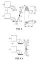
- Fig 2 shows a side view of Fig 1 wherein coils 5 and 6 are in close proximity to each half of the foil 1, in order that coil 5 acts on the positive half of the foil 1 and coil 6 acts on the negative half of the foil 1.
- the EMF 7 of coil 5 has a waveform 9 shown in Fig 2 , which is the main force, driving the oscillation of foil 1, while EMF 7 of coil 6, with waveform 10 provides an opposing control force (negative feedback) to the oscillation of foil 1.
- the action of waveform 10, firstly secures stability of foil 1 oscillation and secondly controls the angular swing motion 11 (A+B) of the foil 1.
- the waveforms 9 and 10 are synchronized to the same frequency 12 however the amplitude 13 of waveform 9 is greater than amplitude 14 of waveform 10.
- the oscillation of foil 1 occurs as follows; when waveform 9 is in the negative (shaded) half of its cycle, it attracts the positive side of foil 1, from the neutral position 15 shown dotted) through angle 11A, while waveform 10, being in the positive (shaded) half of its cycle also attracts the negative side of foil 1, thus providing the necessary opposing control as required.
- Fig 3 illustrates the position of foil 1, when waveform 9 is in its positive (shaded) half of its cycle, whereby it repels the positive half of foil 1 through angle 11B, while waveform 10 being in its negative (shaded) half, also repels the negative half of foil 1, again providing the necessary control as required.
- the torsion axis 2 applies an opposing resistance to the movements of foil 1 which waveform 9 has to overcome in order to produce the required swing motion.
- Fig 4.1 shows the angle of total angular swing of the magnetic foil oscillation of the foil 1, on its axis 2, which is 11 (A+B).
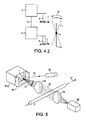
- Fig 4.2 illustrates generators 3/4 in operation, whereby the action of coils 5/6 on foil 1, will cause the foil 1 to oscillate "to and fro" as at 16 on its axis 2, through an angular swing 11 (A+ B) at the same frequency 12 of the generators 3, 4,
- Fig 5 shows the system of the invention in an industrial application whereby a product, this being an electric cable, wire, plastic tube, hose and the like, is progressing in a linear path of travel 17 during its manufacturing process (not shown), comprising the magnetic foil 1 with a mirrored face is supported by a torsion axis 2, in a cradle 18.1, two high frequency generators 3,4 (not shown) with associated induction coils 5, 6 (not shown) in housing 18.2.
- a source 20 such as, laser LED (light emitting diode)
- the rays 21 are directed on to a lens 22 which convert the rays 21 into a sheet or curtain of parallel scanning rays 23, crossing the product P from one side thereof in its path of travel 17.
- a lens 24 positioned on the other side of product P receives rays 23 after passing therethrough and focuses the rays 23 on to a unit 25, which analyses the focussed rays 23, to provide dimensional as well as surface integrity properties of the product 16.
- Fig 6 shows a prior art system comprising a motor M driven multifaceted known polygonal mirrored scanning system G illuminated intermittently with a ray of light from source S.
- the scanning frequency of this system is limited by the rotational speed of the motor M and the number of facets on the mirrored polygon G receiving the beam of light from a light source S.
- a system using this principle could achieve up to 800 scans /sec.
- Fig 7 shows a section of an electric cable profile to be scanned whereby the metallic conductor 26 is insulated with plastic material 27.
- the usual surface faults that may occur during manufacture are ridges 28, valleys 29 and a bare patches 30, any one of which could be 2-3 mm in length.
- the advantage of the present invention in an application of a product travelling at a high manufacturing speed is two-fold, firstly it provides a close coverage of the profile of the product, whereby it measures accurately the diameter or size of the product and secondly, follows closely the contour of the surface profile of the product, thereby locating any faults such as ridges valleys and the like, measuring the size of said faults and itemizing separately the number of each fault as it occurs along the length of said product.
- Fig 8.1 shows a side view of product P, being scanned by a curtain sheet or rays 23 and with reference to Fig 5 , the resultant format of said rays after passing therethrough, are focused by lens 24 on to a photo sensor housed in unit 25.
- the said photo sensor in unit 25 performs spectral analysis of the said resultant rays and produces a waveform as shown in graphical display in Fig 8.2 , which follows accurately the path of said scanned rays as they travel across said product P.
- the X axis in Fig 8.2 represents the light intensity (i) of the said rays and the Y axis represents transit time (t1) of said rays across the aperture of lens 24.
- Fig 8.2 The dimensional and surface imperfections of said product P are derived by time related analysis of the time interval (t2) as depicted in Fig 8.2.
- Fig.9 illustrates a complete system for performing dimensional and surface integrity measurements on an electric cable P in its path of travel 17, comprising unit 26 housing items 18.1, 18.2, 20 and 22 and unit 27 housing items 24 and 25.
- Unit 27 can output all the said measurement information by preferably wireless communication such as "Blue Tooth” and the like, to Display and Data Logging Station Fig 10.
- Fig 11 shows a side view of the invention, which up to this point we have considered as a "single plane", profile system.
- a proprietary Laser Doppler non-contact speed/length Gauge 32 such as the Proton SL3060, shown in Fig, 9 may be employed to provide accurate length information through said wireless transmission to the said Data Logging Station Fig. 10 Fig.
- FIG. 13 illustrates an electric cable P, whereby using the dimensional and surface measurements of unit 27 and the length information from said Proton Gauge 32, the following results are obtained; (a) Product diameter, instant/average, (b) Ridge size/length (c) Valley size/length, (d) Bare Patches length, (e) Distance between successive Ridges, (f) Distance between successive Valleys, (g) Distance between Bare Patches, as well as, Number of Ridges /unit length, Number of Valleys / unit length, and Total Number of Ridges and Valleys.
- the said dimensional measurement and surface integrity results are displayed on the of screen of the Data Logging Station Fig 10 , together with a continuously updating image of cable product P.
- a "freeze frame" facility is available on the said screen, in order to inspect periodically the progress of said product during manufacture.
- An additional advantage of this invention is that the Manufacturer can use the available measurement and surface integrity information for Statistical, as well as Diagnostic purposes, whereby the frequency and location of specific faults can assist in finding which section of the production line, is the cause of the said repetitive faults,
- the facility of data logging the dimensional and surface integrity information as described in this disclosure enables the Manufacturer to set tolerance limits to the particular product under manufacture, thereby a certain amount of small size surface imperfections and or diameter variations, may be acceptable for the intended application and use of that product.
Landscapes
- Physics & Mathematics (AREA)
- General Physics & Mathematics (AREA)
- Biochemistry (AREA)
- Life Sciences & Earth Sciences (AREA)
- Chemical & Material Sciences (AREA)
- Analytical Chemistry (AREA)
- Health & Medical Sciences (AREA)
- General Health & Medical Sciences (AREA)
- Immunology (AREA)
- Pathology (AREA)
- Optics & Photonics (AREA)
- Length Measuring Devices By Optical Means (AREA)
- Investigating Materials By The Use Of Optical Means Adapted For Particular Applications (AREA)
- Length-Measuring Devices Using Wave Or Particle Radiation (AREA)
Abstract
Description
- The present invention relates to a high speed oscillating system for non-contact optical scanning of elongated products moving in a linear production process to determine the dimensional properties and surface profile integrity thereof.
- Industrial products such as wires, cable, tubes, ropes and similarly elongated products which are manufactured in continuous linear processes are required to be measured by preferably non-contact methods, to determine the overall size as well as the surface integrity of the profile of the product.
- These measurements usually take place while the products are being manufactured in various processes, including extrusion in the case of plastic cables, tubes etc. or drawing machinery, in the case wires, metallic tubes and the like, Measurements at the point of manufacture are necessary, firstly to ensure compliance to specification requirements, and secondly to check on the surface integrity of the finished product.
- The primary measurement applied to linearly manufactured elongated products is the diameter or size of the said product, and this is done preferably by optical non-contact devices. Quality control, or surface integrity of the said product, is performed in a similar manner by an optical device whereby, the profile of the said product is examined to ensure that there is no damage or faults, such as ridges valleys and the like, to the surface of the said product. In the prior art in existence at the time when the present invention was envisioned, two alternative optical systems existed, one for dimensional measurements of the said product and an alternative system for checking the surface integrity of the said product. These prior art systems will be explained later in this text.
- It is the object of this invention to obviate problems and drawbacks of the prior art, by making use of apparatus and methods that increase the scanning frequency of an optical dimensional measuring device, having the capability to measure the diameter or size of a moving product and at the same time check the surface integrity of the product simultaneously, during the manufacturing process of the product.
- Apparatus for high frequency scanning of a product being manufactured in a continuous linear process comprising two high frequency generators for providing output frequencies of equal magnitude but of opposing phase, a magnetic foil with a mirrored face mounted for oscillation on a torsion axis, a light source for projecting a ray of light from the source onto the foil, a pair of induction coils operatively associated with said generators whereby to generate electromagnetic forces of opposite polarity under the influence of said generators to oscillate the foil to direct successive curtains of parallel rays across the product in its linear path of travel to scan the product at the frequency of the generators, detector means for receiving the resulting format of the parallel rays of light on the other side of the product after the passage of the product there through ,analysis means for analysing the format of the resulting light rays and adapted to provide dimensional measurements and surface integrity of the product.
- The present invention will now be described by reference to the accompanying drawings wherein.
-
Fig 1 shows in perspective view the main elements of a preferred embodiment of the invention. -
Fig 2 andFig 3 show side views ofFig 1 illustrating the principle of operation of the invention. -
Fig 4.1 andFig 4 ,2 show the operating principles of the invention in detail. -
Fig 5 illustrates the application of the invention to the measurement of dimensions as well as surface imperfections in an extruded product. -
Fig 6 shows a prior art device. -
Fig 7 illustrates a section of an electric cable formed in an extrusion process with surface faults. -
Fig 8.1 and Fig 8.2 show respectively a cross-sectional view of a product being scanned by a curtain of rays and a graphical display of the spectral analysis of the rays after scanning the product. -
Fig 9 illustrates a complete system for performing dimensional and surface integrity measurements on a travelling product. -
Fig 10 is illustrative of a data logging station for displaying the diameter, surface faults and statistics resulting from the scanning of a product. -
Fig 11 is illustrative of a side view of the measuring system being a single plane profile system with reference to the scanning of a product. -
Fig 12 is an alternative form of the system shown inFig 11 but capable of oscillatory motion about the product and; -
Fig 13 illustrates the various imperfections detected by the measuring system for display on the data logging station shown inFig 10 . - Preferred embodiments of the invention are shown in
Figures 1-7 . - During the following discussion, reference will be made to
Figures 1-7 and when similar items of the apparatus are used, they will be referred to with identical reference numbers. -
- meters per minute = m/min
- meters per second = m/sec
- millimetres per second = mm/sec
- cycles per second = cycles/sec
- scans per second = scans/sec
- With reference to
Fig 1 this illustrates a high frequency oscillating system, comprising a foil 1, magnetized in a plus (+) and minus (-) manner, being supported by atorsion axis 2, preferably twohigh frequency generators generators induction coils coil 5 is directed to the positive half of the foil 1 andcoil 6 is directed to the negative half of the coil 1. - The
generators connection 8 in such a manner, whereby the output frequencies of thegenerators Fig 2 ). -
Fig 2 shows a side view ofFig 1 whereincoils coil 5 acts on the positive half of the foil 1 andcoil 6 acts on the negative half of the foil 1. - The
EMF 7 ofcoil 5 has awaveform 9 shown inFig 2 , which is the main force, driving the oscillation of foil 1, while EMF 7 ofcoil 6, with waveform 10 provides an opposing control force (negative feedback) to the oscillation of foil 1. The action of waveform 10, firstly secures stability of foil 1 oscillation and secondly controls the angular swing motion 11 (A+B) of the foil 1. - As previously mentioned, the
waveforms 9 and 10 are synchronized to thesame frequency 12 however theamplitude 13 ofwaveform 9 is greater than amplitude 14 of waveform 10. - The oscillation of foil 1 occurs as follows; when
waveform 9 is in the negative (shaded) half of its cycle, it attracts the positive side of foil 1, from theneutral position 15 shown dotted) throughangle 11A, while waveform 10, being in the positive (shaded) half of its cycle also attracts the negative side of foil 1, thus providing the necessary opposing control as required. -
Fig 3 illustrates the position of foil 1, whenwaveform 9 is in its positive (shaded) half of its cycle, whereby it repels the positive half of foil 1 throughangle 11B, while waveform 10 being in its negative (shaded) half, also repels the negative half of foil 1, again providing the necessary control as required. Thetorsion axis 2 applies an opposing resistance to the movements of foil 1 whichwaveform 9 has to overcome in order to produce the required swing motion. -
Fig 4.1 shows the angle of total angular swing of the magnetic foil oscillation of the foil 1, on itsaxis 2, which is 11 (A+B). - When the system is not in operation the
torsion axis 2 returns foil 1 to therest position 15. -
Fig 4.2 illustratesgenerators 3/4 in operation, whereby the action ofcoils 5/6 on foil 1, will cause the foil 1 to oscillate "to and fro" as at 16 on itsaxis 2, through an angular swing 11 (A+ B) at thesame frequency 12 of thegenerators - As foil 1 oscillates in a "to and fro" motion, this equates to 2 scans per one single cycle of
frequency 12. This is a very useful advantage, as it doubles the frequency ofgenerators 3/4. Theoscillation frequency 12 which can be achieved using this principle is up to 20,000 cycles/sec, which equates to 40,000 scans/sec of foil 1, thus providing a considerable advantage in industrial applications for dimensional measurements of products, as well as their surface integrity. -
Fig 5 shows the system of the invention in an industrial application whereby a product, this being an electric cable, wire, plastic tube, hose and the like, is progressing in a linear path oftravel 17 during its manufacturing process (not shown), comprising the magnetic foil 1 with a mirrored face is supported by atorsion axis 2, in a cradle 18.1, twohigh frequency generators 3,4 (not shown) with associatedinduction coils 5, 6 (not shown) in housing 18.2. - A ray of
light 19 from asource 20, such as, laser LED (light emitting diode), is directed on to the mirrored face of foil 1, and by the action of the oscillating foil 1, a series ofconsecutive rays 21 are produced. - The
rays 21 are directed on to alens 22 which convert therays 21 into a sheet or curtain ofparallel scanning rays 23, crossing the product P from one side thereof in its path oftravel 17. - A
lens 24 positioned on the other side of product P receivesrays 23 after passing therethrough and focuses therays 23 on to aunit 25, which analyses the focussedrays 23, to provide dimensional as well as surface integrity properties of theproduct 16. - In order to illustrate the advantages of the invention in more detail, reference is made to
Fig 6 and Fig 7 whereby the invention will be compared with known prior art. -
Fig 6 shows a prior art system comprising a motor M driven multifaceted known polygonal mirrored scanning system G illuminated intermittently with a ray of light from source S. - As obvious to one skilled in the arts, the scanning frequency of this system is limited by the rotational speed of the motor M and the number of facets on the mirrored polygon G receiving the beam of light from a light source S. In practice, a system using this principle, could achieve up to 800 scans /sec.
- By way of example of the operation of the prior art,
Fig 7 shows a section of an electric cable profile to be scanned whereby themetallic conductor 26 is insulated withplastic material 27. The usual surface faults that may occur during manufacture areridges 28,valleys 29 and abare patches 30, any one of which could be 2-3 mm in length. Let us assume that this cable was manufactured at a production speed of 1,200 meters/min, or 20,000 mm/sec, the distance between two successive scans, using the 800 scan system ofFig 6 , will be 20,000/ 800 = 25mm. Therefore the illustrated prior art system is unlikely to detect any of the said surface faults. - In other known prior art, an alternative non-scanning optical system exists, for checking surface integrity, which operates on the Shadow-Graph principle, by responding to changes in light intensity, thereby detecting surface imperfections. This system will detect the ridges, valleys and bare patches shown in
Fig 7 and provide a count of the number of the ridges, valleys and bare patches but does not supply any other information. - By comparison with the prior art as described in the system of the present invention as noted in
Fig 4.2 , is capable of operating at a scanning frequency of 40,000 scans/sec. Therefore considering the example inFig 5 of a production line running at a speed of 1,200 m/ min or 20,000 mm/sec, the distance between two successive scans will be 20,000/ 40,000 mm, that means 2 scans per 0.5 mm of product length. - It is obvious from this example that the advantage of the present invention in an application of a product travelling at a high manufacturing speed is two-fold, firstly it provides a close coverage of the profile of the product, whereby it measures accurately the diameter or size of the product and secondly, follows closely the contour of the surface profile of the product, thereby locating any faults such as ridges valleys and the like, measuring the size of said faults and itemizing separately the number of each fault as it occurs along the length of said product.
- The operation of the invention will now be explained in more detail.
-
Fig 8.1 shows a side view of product P, being scanned by a curtain sheet or rays 23 and with reference toFig 5 , the resultant format of said rays after passing therethrough, are focused bylens 24 on to a photo sensor housed inunit 25. The said photo sensor inunit 25 performs spectral analysis of the said resultant rays and produces a waveform as shown in graphical display inFig 8.2 , which follows accurately the path of said scanned rays as they travel across said product P. The X axis inFig 8.2 represents the light intensity (i) of the said rays and the Y axis represents transit time (t1) of said rays across the aperture oflens 24. The dimensional and surface imperfections of said product P are derived by time related analysis of the time interval (t2) as depicted inFig 8.2. Fig.9 , illustrates a complete system for performing dimensional and surface integrity measurements on an electric cable P in its path oftravel 17, comprisingunit 26 housing items 18.1, 18.2, 20 and 22 andunit 27housing items -
Unit 27 can output all the said measurement information by preferably wireless communication such as "Blue Tooth" and the like, to Display and Data Logging StationFig 10. Fig 11 shows a side view of the invention, which up to this point we have considered as a "single plane", profile system. - However it will be obvious to a person familiar with the arts, that some
surface imperfections 28, shown inFig.11 , will be missed, as these are on the "blind" side of the profile. For this purpose a "two plane" profile system is used 29 (shown dotted), to overcome this problem. In high quality product requirements, a "three plane" profile system (not shown) is recommended. As a more cost effective solution to overcome the all-round detection of surface imperfections, a "single plane" system may be usedFig. 12 , whereby it oscillates in a "to and fro"motion 30 about the centre of the travelling cable product P, or alternatively rotates in acontinuous motion 31 around said product P. - In order to further enhance the application usefulness of the present invention, a proprietary Laser Doppler non-contact speed/
length Gauge 32, such as the Proton SL3060, shown inFig, 9 may be employed to provide accurate length information through said wireless transmission to the said Data Logging StationFig. 10 Fig. 13 illustrates an electric cable P, whereby using the dimensional and surface measurements ofunit 27 and the length information from saidProton Gauge 32, the following results are obtained; (a) Product diameter, instant/average, (b) Ridge size/length (c) Valley size/length, (d) Bare Patches length, (e) Distance between successive Ridges, (f) Distance between successive Valleys, (g) Distance between Bare Patches, as well as, Number of Ridges /unit length, Number of Valleys / unit length, and Total Number of Ridges and Valleys. The said dimensional measurement and surface integrity results are displayed on the of screen of the Data Logging StationFig 10 , together with a continuously updating image of cable product P. A "freeze frame" facility is available on the said screen, in order to inspect periodically the progress of said product during manufacture. - When Bare Patches are detected, production stops and the cable run has to be scrapped. However if the Bare Patches are detected near the end of the cable run, it may be possible to salvage part of the cable. An additional advantage of this invention is that the Manufacturer can use the available measurement and surface integrity information for Statistical, as well as Diagnostic purposes, whereby the frequency and location of specific faults can assist in finding which section of the production line, is the cause of the said repetitive faults, The facility of data logging the dimensional and surface integrity information as described in this disclosure, enables the Manufacturer to set tolerance limits to the particular product under manufacture, thereby a certain amount of small size surface imperfections and or diameter variations, may be acceptable for the intended application and use of that product.
Claims (8)
- Apparatus for high frequency scanning of a product being manufactured in a continuous linear process comprising two high frequency generators for providing output frequencies of equal magnitude but of opposing phase, a magnetic foil with a mirrored face mounted for oscillation on a torsion axis, a light source for projecting a ray of light from the source onto the foil, a pair of induction coils operatively associated with said generators whereby to generate electromagnetic forces of opposite polarity under the influence of said generators to oscillate the foil and direct successive curtains of parallel rays across the product in its linear path of travel to scan the product at the frequency of the generators ,detector means for receiving the resulting format of the parallel rays of light on the other side of the product after the passage of the product, there through and analysis means for analysing the format of the resulting light rays light and adapted to provide dimensional measurements and surface integrity, of the product.
- Apparatus as claimed in claim 1, whereby the high frequency generators with their associated induction coils, produce an electromagnetic force (EMF) which is directed onto the magnetic foil with a mirrored face, whereby the action of the said EMF on the magnetic foil, causes the magnetic foil to oscillate about its torsion axis, at the same frequency of the high frequency generators.
- Apparatus as claimed in claim 2 whereby one of said high frequency generators and associated induction coil, provide the main electronic driving force, to cause the oscillation of said, mirrored foil.
- Apparatus as claimed in claim 2 whereby the other of said two high frequency generators and associated induction coil, provides an opposing electromagnetic force to said driving force, in order to stabilize the oscillation of said mirrored foil and control the angular extent of the rocking motion of said foil,
- Apparatus as claimed in any preceding claim wherein the source of light is provided by a laser or light emitting diode which directs a ray on to the mirrored face of said oscillating magnetic foil, thereby to create a series of consecutive rays, a first lens for receiving said consecutive rays to produce a curtain of parallel rays to be scanned across the product from one side thereof, a second lens for focusing said rays after being intercepted by said moving product system for analysis by said analysis means to determine the dimensional properties and surface integrity of the product.
- Apparatus for high frequency scanning of a moving product being manufactured in a continuous linear process to determine its dimensional proportion and constructional integrity comprising two high frequency generators with two associated induction coils, a magnetic foil with a mirrored face suspended on a torsion axis to permit oscillating motion thereof, a source producing a ray of light directed onto said foil, means for oscillating the magnetic foil under the influence of electromagnetic forces of opposite polarity applied thereto from said induction coils to provide successive curtains of parallel rays of light through which the product passes in its path of travel, means for receiving the resulting format of the curtain of parallel rays after modification of its format by passage of the product there through, means of analysing the said modified format in order to locate and detect surface faults such as, ridges, valleys, bare patches, in the profile contour of said product and means for measuring and individually itemising said faults in order to ensure the suitability of the product for its subsequent application.
- A device for use in an optical scanner comprising a pair of generators for providing output frequencies of equal magnitude but in opposing phase, a magnetic foil mounted for oscillation on a torsion axis, and a pair of induction coils operatively associated with said generators whereby to generate electromagnetic forces of opposite polarity under the influence of said generators directed onto the foil to oscillate the foil.
- A device as claimed in claim 7 wherein the foil is mirrored.
Applications Claiming Priority (2)
| Application Number | Priority Date | Filing Date | Title |
|---|---|---|---|
| GBGB1401564.8A GB201401564D0 (en) | 2014-01-30 | 2014-01-30 | A high speed magnetic oscillating device |
| GBGB1402987.0A GB201402987D0 (en) | 2014-01-30 | 2014-02-20 | A high speed magnetic oscillating device |
Publications (2)
| Publication Number | Publication Date |
|---|---|
| EP2902837A1 true EP2902837A1 (en) | 2015-08-05 |
| EP2902837B1 EP2902837B1 (en) | 2018-12-26 |
Family
ID=50344075
Family Applications (1)
| Application Number | Title | Priority Date | Filing Date |
|---|---|---|---|
| EP14003870.4A Active EP2902837B1 (en) | 2014-01-30 | 2014-11-18 | A high speed magnetic oscillating device |
Country Status (4)
| Country | Link |
|---|---|
| US (1) | US9528821B2 (en) |
| EP (1) | EP2902837B1 (en) |
| CN (1) | CN104819688B (en) |
| GB (2) | GB201401564D0 (en) |
Cited By (1)
| Publication number | Priority date | Publication date | Assignee | Title |
|---|---|---|---|---|
| CN109279441A (en) * | 2017-07-21 | 2019-01-29 | 苏州凌犀物联网技术有限公司 | Bulge detection device and detection method in a kind of automatic winding displacement control system |
Families Citing this family (2)
| Publication number | Priority date | Publication date | Assignee | Title |
|---|---|---|---|---|
| JP6974973B2 (en) * | 2017-07-27 | 2021-12-01 | キヤノン電子株式会社 | Optical scanning measuring device |
| US11524136B2 (en) * | 2018-12-24 | 2022-12-13 | Biosense Webster (Israel) Ltd. | Non-invasive measurement of the pitch of a braid |
Citations (3)
| Publication number | Priority date | Publication date | Assignee | Title |
|---|---|---|---|---|
| WO1995029396A1 (en) * | 1994-04-27 | 1995-11-02 | Commonwealth Scientific And Industrial Research Organisation | Methods and apparatus for determining a first parameter(s) of an object |
| US6108118A (en) * | 1998-07-09 | 2000-08-22 | Olympus Optical Co., Ltd. | Optical deflector |
| DE202013103566U1 (en) * | 2013-08-08 | 2013-08-21 | Femotech Gmbh | Optical resonance scanner |
Family Cites Families (22)
| Publication number | Priority date | Publication date | Assignee | Title |
|---|---|---|---|---|
| NL8001617A (en) * | 1980-03-19 | 1981-10-16 | Philips Nv | DEVICE FOR ELECTRODYNAMICALLY CONTROLLED SWIVING OF AN OPTICAL ELEMENT. |
| IL87252A (en) * | 1988-07-28 | 1992-03-29 | Israel State | Scanning device |
| GB8829250D0 (en) * | 1988-12-15 | 1989-01-25 | Beta Instr Co | System for determining the dimension of an object |
| US4958894A (en) * | 1989-01-23 | 1990-09-25 | Metrologic Instruments, Inc. | Bouncing oscillating scanning device for laser scanning apparatus |
| US5099352A (en) | 1989-10-13 | 1992-03-24 | Mitsubishi Denki Kabushiki Kaisha | Reflector oscillating apparatus |
| US5610752A (en) | 1992-05-27 | 1997-03-11 | Opticon Inc. | Optical reader with vibrating mirror |
| US5621529A (en) | 1995-04-05 | 1997-04-15 | Intelligent Automation Systems, Inc. | Apparatus and method for projecting laser pattern with reduced speckle noise |
| US5982521A (en) * | 1995-11-15 | 1999-11-09 | Brother Kogyo Kabushiki Kaisha | Optical scanner |
| US6882462B2 (en) | 2002-11-01 | 2005-04-19 | Microvision, Inc. | Resonant scanner with asymmetric mass distribution |
| US7061628B2 (en) * | 2001-06-27 | 2006-06-13 | Southwest Research Institute | Non-contact apparatus and method for measuring surface profile |
| JP4307171B2 (en) | 2002-07-19 | 2009-08-05 | キヤノン株式会社 | Micro movable body |
| GB0306468D0 (en) * | 2003-03-20 | 2003-04-23 | Molins Plc | A method and apparatus for determining one or more physical properties of a rolled smoking article or filter rod |
| US7442918B2 (en) | 2004-05-14 | 2008-10-28 | Microvision, Inc. | MEMS device having simplified drive |
| KR100709558B1 (en) | 2005-09-01 | 2007-04-20 | 삼성전기주식회사 | Vibrating Tilting Device |
| TWI304394B (en) * | 2006-07-03 | 2008-12-21 | Nat Univ Tsing Hua | Magnetic element and manufacturing process, driving structure and driving method therefor |
| JP2009058930A (en) * | 2007-08-07 | 2009-03-19 | Canon Inc | Oscillator device, optical deflector, and optical apparatus using the same |
| JP2009042322A (en) * | 2007-08-07 | 2009-02-26 | Canon Inc | Oscillator device, optical deflector, and optical apparatus using the same |
| US8094352B2 (en) | 2008-05-13 | 2012-01-10 | Texas Instruments Incorporated | Mirror assembly with recessed mirror |
| CZ2010423A3 (en) * | 2010-05-28 | 2010-08-18 | Perner@Petr | Method and apparatus for continuous detection of thickness and/or homogeneity of a linear configuration, especially textile fiber |
| JP6111532B2 (en) * | 2012-05-11 | 2017-04-12 | セイコーエプソン株式会社 | Optical device, optical scanner, and image display device |
| US9488829B2 (en) * | 2012-12-21 | 2016-11-08 | Mitsubishi Electric Corporation | Optical scanning device and projector |
| US9128190B1 (en) * | 2013-03-06 | 2015-09-08 | Google Inc. | Light steering device with an array of oscillating reflective slats |
-
2014
- 2014-01-30 GB GBGB1401564.8A patent/GB201401564D0/en not_active Ceased
- 2014-02-20 GB GBGB1402987.0A patent/GB201402987D0/en not_active Ceased
- 2014-11-18 EP EP14003870.4A patent/EP2902837B1/en active Active
-
2015
- 2015-01-22 CN CN201510031565.0A patent/CN104819688B/en active Active
- 2015-01-28 US US14/607,437 patent/US9528821B2/en active Active
Patent Citations (3)
| Publication number | Priority date | Publication date | Assignee | Title |
|---|---|---|---|---|
| WO1995029396A1 (en) * | 1994-04-27 | 1995-11-02 | Commonwealth Scientific And Industrial Research Organisation | Methods and apparatus for determining a first parameter(s) of an object |
| US6108118A (en) * | 1998-07-09 | 2000-08-22 | Olympus Optical Co., Ltd. | Optical deflector |
| DE202013103566U1 (en) * | 2013-08-08 | 2013-08-21 | Femotech Gmbh | Optical resonance scanner |
Cited By (2)
| Publication number | Priority date | Publication date | Assignee | Title |
|---|---|---|---|---|
| CN109279441A (en) * | 2017-07-21 | 2019-01-29 | 苏州凌犀物联网技术有限公司 | Bulge detection device and detection method in a kind of automatic winding displacement control system |
| CN109279441B (en) * | 2017-07-21 | 2021-12-10 | 苏州凌犀物联网技术有限公司 | Bulge detection device and detection method in automatic wire arranging control system |
Also Published As
| Publication number | Publication date |
|---|---|
| CN104819688B (en) | 2017-12-26 |
| GB201401564D0 (en) | 2014-03-19 |
| EP2902837B1 (en) | 2018-12-26 |
| US20150211982A1 (en) | 2015-07-30 |
| CN104819688A (en) | 2015-08-05 |
| GB201402987D0 (en) | 2014-04-09 |
| US9528821B2 (en) | 2016-12-27 |
Similar Documents
| Publication | Publication Date | Title |
|---|---|---|
| JP5424196B2 (en) | Air gap inspection device | |
| US9279662B2 (en) | Laser scanner | |
| CN104375141A (en) | Millimeter wave three-dimensional holoscan imaging device and checking method | |
| US20150324991A1 (en) | Method for capturing images of a preferably structured surface of an object and device for image capture | |
| US4766323A (en) | Method and apparatus for determining the distance of an object | |
| US9528821B2 (en) | High speed magnetic oscillating device | |
| JP6258993B2 (en) | Measurement of industrial products produced by extrusion technology | |
| CN113446966A (en) | Method and device for measuring straightness of end of steel pipe | |
| US10422621B2 (en) | Optical measurement device having a plurality of rotary shafts and displacement detectors for detecting axial displacement of each rotary shaft and using the detected axial displacement for three-dimensional image correction | |
| JP2015081857A (en) | Belt inspection method for belt conveyor | |
| CN108700407B (en) | Device for measuring parameters of a cable | |
| CN102788573B (en) | Line structure light positioning projection image acquisition device | |
| CN106931911A (en) | The confocal line scanning device of white-light spectrum | |
| JP7271866B2 (en) | Magnetic inspection system and program | |
| US20050002036A1 (en) | Method and apparatus for measuring a pitch of stranded cable | |
| CN110226075A (en) | Detection device | |
| US9625421B2 (en) | Manually operated small envelope scanner system | |
| JP2016537632A (en) | Distance measuring device and distance measurement starting point search method | |
| CN212207699U (en) | Security inspection device based on millimeter wave imaging | |
| FR2535849A1 (en) | METHOD FOR DETERMINING THE POSITION OF A MEASURING PROBE | |
| CN111614950A (en) | Lens detection device | |
| EP4715373A1 (en) | Cable inspection system | |
| CN111650182B (en) | A three-dimensional laser Raman spectroscopy scanner | |
| KR101740251B1 (en) | Apparatus for checking twisted-brush and inspection method it | |
| RU2548939C2 (en) | Method for determining angular positions of object surface and device for its implementation |
Legal Events
| Date | Code | Title | Description |
|---|---|---|---|
| PUAI | Public reference made under article 153(3) epc to a published international application that has entered the european phase |
Free format text: ORIGINAL CODE: 0009012 |
|
| 17P | Request for examination filed |
Effective date: 20141118 |
|
| AK | Designated contracting states |
Kind code of ref document: A1 Designated state(s): AL AT BE BG CH CY CZ DE DK EE ES FI FR GB GR HR HU IE IS IT LI LT LU LV MC MK MT NL NO PL PT RO RS SE SI SK SM TR |
|
| AX | Request for extension of the european patent |
Extension state: BA ME |
|
| RBV | Designated contracting states (corrected) |
Designated state(s): AL AT BE BG CH CY CZ DE DK EE ES FI FR GB GR HR HU IE IS IT LI LT LU LV MC MK MT NL NO PL PT RO RS SE SI SK SM TR |
|
| 17P | Request for examination filed |
Effective date: 20160104 |
|
| RIC1 | Information provided on ipc code assigned before grant |
Ipc: G02B 26/10 20060101AFI20180518BHEP Ipc: G01B 11/24 20060101ALI20180518BHEP Ipc: G01B 11/10 20060101ALI20180518BHEP Ipc: G01N 21/952 20060101ALI20180518BHEP |
|
| GRAP | Despatch of communication of intention to grant a patent |
Free format text: ORIGINAL CODE: EPIDOSNIGR1 |
|
| STAA | Information on the status of an ep patent application or granted ep patent |
Free format text: STATUS: GRANT OF PATENT IS INTENDED |
|
| INTG | Intention to grant announced |
Effective date: 20180703 |
|
| GRAS | Grant fee paid |
Free format text: ORIGINAL CODE: EPIDOSNIGR3 |
|
| GRAA | (expected) grant |
Free format text: ORIGINAL CODE: 0009210 |
|
| STAA | Information on the status of an ep patent application or granted ep patent |
Free format text: STATUS: THE PATENT HAS BEEN GRANTED |
|
| AK | Designated contracting states |
Kind code of ref document: B1 Designated state(s): AL AT BE BG CH CY CZ DE DK EE ES FI FR GB GR HR HU IE IS IT LI LT LU LV MC MK MT NL NO PL PT RO RS SE SI SK SM TR |
|
| REG | Reference to a national code |
Ref country code: GB Ref legal event code: FG4D |
|
| REG | Reference to a national code |
Ref country code: CH Ref legal event code: EP |
|
| REG | Reference to a national code |
Ref country code: AT Ref legal event code: REF Ref document number: 1082208 Country of ref document: AT Kind code of ref document: T Effective date: 20190115 |
|
| REG | Reference to a national code |
Ref country code: DE Ref legal event code: R096 Ref document number: 602014038456 Country of ref document: DE |
|
| REG | Reference to a national code |
Ref country code: IE Ref legal event code: FG4D |
|
| PG25 | Lapsed in a contracting state [announced via postgrant information from national office to epo] |
Ref country code: NO Free format text: LAPSE BECAUSE OF FAILURE TO SUBMIT A TRANSLATION OF THE DESCRIPTION OR TO PAY THE FEE WITHIN THE PRESCRIBED TIME-LIMIT Effective date: 20190326 Ref country code: LT Free format text: LAPSE BECAUSE OF FAILURE TO SUBMIT A TRANSLATION OF THE DESCRIPTION OR TO PAY THE FEE WITHIN THE PRESCRIBED TIME-LIMIT Effective date: 20181226 Ref country code: HR Free format text: LAPSE BECAUSE OF FAILURE TO SUBMIT A TRANSLATION OF THE DESCRIPTION OR TO PAY THE FEE WITHIN THE PRESCRIBED TIME-LIMIT Effective date: 20181226 Ref country code: BG Free format text: LAPSE BECAUSE OF FAILURE TO SUBMIT A TRANSLATION OF THE DESCRIPTION OR TO PAY THE FEE WITHIN THE PRESCRIBED TIME-LIMIT Effective date: 20190326 Ref country code: LV Free format text: LAPSE BECAUSE OF FAILURE TO SUBMIT A TRANSLATION OF THE DESCRIPTION OR TO PAY THE FEE WITHIN THE PRESCRIBED TIME-LIMIT Effective date: 20181226 Ref country code: FI Free format text: LAPSE BECAUSE OF FAILURE TO SUBMIT A TRANSLATION OF THE DESCRIPTION OR TO PAY THE FEE WITHIN THE PRESCRIBED TIME-LIMIT Effective date: 20181226 |
|
| REG | Reference to a national code |
Ref country code: NL Ref legal event code: MP Effective date: 20181226 |
|
| REG | Reference to a national code |
Ref country code: LT Ref legal event code: MG4D |
|
| PG25 | Lapsed in a contracting state [announced via postgrant information from national office to epo] |
Ref country code: AL Free format text: LAPSE BECAUSE OF FAILURE TO SUBMIT A TRANSLATION OF THE DESCRIPTION OR TO PAY THE FEE WITHIN THE PRESCRIBED TIME-LIMIT Effective date: 20181226 Ref country code: SE Free format text: LAPSE BECAUSE OF FAILURE TO SUBMIT A TRANSLATION OF THE DESCRIPTION OR TO PAY THE FEE WITHIN THE PRESCRIBED TIME-LIMIT Effective date: 20181226 Ref country code: RS Free format text: LAPSE BECAUSE OF FAILURE TO SUBMIT A TRANSLATION OF THE DESCRIPTION OR TO PAY THE FEE WITHIN THE PRESCRIBED TIME-LIMIT Effective date: 20181226 Ref country code: GR Free format text: LAPSE BECAUSE OF FAILURE TO SUBMIT A TRANSLATION OF THE DESCRIPTION OR TO PAY THE FEE WITHIN THE PRESCRIBED TIME-LIMIT Effective date: 20190327 |
|
| REG | Reference to a national code |
Ref country code: AT Ref legal event code: MK05 Ref document number: 1082208 Country of ref document: AT Kind code of ref document: T Effective date: 20181226 |
|
| PG25 | Lapsed in a contracting state [announced via postgrant information from national office to epo] |
Ref country code: NL Free format text: LAPSE BECAUSE OF FAILURE TO SUBMIT A TRANSLATION OF THE DESCRIPTION OR TO PAY THE FEE WITHIN THE PRESCRIBED TIME-LIMIT Effective date: 20181226 |
|
| PG25 | Lapsed in a contracting state [announced via postgrant information from national office to epo] |
Ref country code: PL Free format text: LAPSE BECAUSE OF FAILURE TO SUBMIT A TRANSLATION OF THE DESCRIPTION OR TO PAY THE FEE WITHIN THE PRESCRIBED TIME-LIMIT Effective date: 20181226 Ref country code: ES Free format text: LAPSE BECAUSE OF FAILURE TO SUBMIT A TRANSLATION OF THE DESCRIPTION OR TO PAY THE FEE WITHIN THE PRESCRIBED TIME-LIMIT Effective date: 20181226 Ref country code: IT Free format text: LAPSE BECAUSE OF FAILURE TO SUBMIT A TRANSLATION OF THE DESCRIPTION OR TO PAY THE FEE WITHIN THE PRESCRIBED TIME-LIMIT Effective date: 20181226 Ref country code: CZ Free format text: LAPSE BECAUSE OF FAILURE TO SUBMIT A TRANSLATION OF THE DESCRIPTION OR TO PAY THE FEE WITHIN THE PRESCRIBED TIME-LIMIT Effective date: 20181226 Ref country code: PT Free format text: LAPSE BECAUSE OF FAILURE TO SUBMIT A TRANSLATION OF THE DESCRIPTION OR TO PAY THE FEE WITHIN THE PRESCRIBED TIME-LIMIT Effective date: 20190426 |
|
| PG25 | Lapsed in a contracting state [announced via postgrant information from national office to epo] |
Ref country code: RO Free format text: LAPSE BECAUSE OF FAILURE TO SUBMIT A TRANSLATION OF THE DESCRIPTION OR TO PAY THE FEE WITHIN THE PRESCRIBED TIME-LIMIT Effective date: 20181226 Ref country code: IS Free format text: LAPSE BECAUSE OF FAILURE TO SUBMIT A TRANSLATION OF THE DESCRIPTION OR TO PAY THE FEE WITHIN THE PRESCRIBED TIME-LIMIT Effective date: 20190426 Ref country code: EE Free format text: LAPSE BECAUSE OF FAILURE TO SUBMIT A TRANSLATION OF THE DESCRIPTION OR TO PAY THE FEE WITHIN THE PRESCRIBED TIME-LIMIT Effective date: 20181226 Ref country code: SM Free format text: LAPSE BECAUSE OF FAILURE TO SUBMIT A TRANSLATION OF THE DESCRIPTION OR TO PAY THE FEE WITHIN THE PRESCRIBED TIME-LIMIT Effective date: 20181226 Ref country code: SK Free format text: LAPSE BECAUSE OF FAILURE TO SUBMIT A TRANSLATION OF THE DESCRIPTION OR TO PAY THE FEE WITHIN THE PRESCRIBED TIME-LIMIT Effective date: 20181226 |
|
| REG | Reference to a national code |
Ref country code: DE Ref legal event code: R097 Ref document number: 602014038456 Country of ref document: DE |
|
| PG25 | Lapsed in a contracting state [announced via postgrant information from national office to epo] |
Ref country code: DK Free format text: LAPSE BECAUSE OF FAILURE TO SUBMIT A TRANSLATION OF THE DESCRIPTION OR TO PAY THE FEE WITHIN THE PRESCRIBED TIME-LIMIT Effective date: 20181226 Ref country code: AT Free format text: LAPSE BECAUSE OF FAILURE TO SUBMIT A TRANSLATION OF THE DESCRIPTION OR TO PAY THE FEE WITHIN THE PRESCRIBED TIME-LIMIT Effective date: 20181226 |
|
| PLBE | No opposition filed within time limit |
Free format text: ORIGINAL CODE: 0009261 |
|
| STAA | Information on the status of an ep patent application or granted ep patent |
Free format text: STATUS: NO OPPOSITION FILED WITHIN TIME LIMIT |
|
| 26N | No opposition filed |
Effective date: 20190927 |
|
| PG25 | Lapsed in a contracting state [announced via postgrant information from national office to epo] |
Ref country code: SI Free format text: LAPSE BECAUSE OF FAILURE TO SUBMIT A TRANSLATION OF THE DESCRIPTION OR TO PAY THE FEE WITHIN THE PRESCRIBED TIME-LIMIT Effective date: 20181226 |
|
| PG25 | Lapsed in a contracting state [announced via postgrant information from national office to epo] |
Ref country code: TR Free format text: LAPSE BECAUSE OF FAILURE TO SUBMIT A TRANSLATION OF THE DESCRIPTION OR TO PAY THE FEE WITHIN THE PRESCRIBED TIME-LIMIT Effective date: 20181226 |
|
| REG | Reference to a national code |
Ref country code: CH Ref legal event code: PL |
|
| PG25 | Lapsed in a contracting state [announced via postgrant information from national office to epo] |
Ref country code: CH Free format text: LAPSE BECAUSE OF NON-PAYMENT OF DUE FEES Effective date: 20191130 Ref country code: LU Free format text: LAPSE BECAUSE OF NON-PAYMENT OF DUE FEES Effective date: 20191118 Ref country code: LI Free format text: LAPSE BECAUSE OF NON-PAYMENT OF DUE FEES Effective date: 20191130 Ref country code: MC Free format text: LAPSE BECAUSE OF FAILURE TO SUBMIT A TRANSLATION OF THE DESCRIPTION OR TO PAY THE FEE WITHIN THE PRESCRIBED TIME-LIMIT Effective date: 20181226 |
|
| REG | Reference to a national code |
Ref country code: BE Ref legal event code: MM Effective date: 20191130 |
|
| PG25 | Lapsed in a contracting state [announced via postgrant information from national office to epo] |
Ref country code: IE Free format text: LAPSE BECAUSE OF NON-PAYMENT OF DUE FEES Effective date: 20191118 |
|
| PG25 | Lapsed in a contracting state [announced via postgrant information from national office to epo] |
Ref country code: BE Free format text: LAPSE BECAUSE OF NON-PAYMENT OF DUE FEES Effective date: 20191130 |
|
| PG25 | Lapsed in a contracting state [announced via postgrant information from national office to epo] |
Ref country code: CY Free format text: LAPSE BECAUSE OF FAILURE TO SUBMIT A TRANSLATION OF THE DESCRIPTION OR TO PAY THE FEE WITHIN THE PRESCRIBED TIME-LIMIT Effective date: 20181226 |
|
| PG25 | Lapsed in a contracting state [announced via postgrant information from national office to epo] |
Ref country code: HU Free format text: LAPSE BECAUSE OF FAILURE TO SUBMIT A TRANSLATION OF THE DESCRIPTION OR TO PAY THE FEE WITHIN THE PRESCRIBED TIME-LIMIT; INVALID AB INITIO Effective date: 20141118 Ref country code: MT Free format text: LAPSE BECAUSE OF FAILURE TO SUBMIT A TRANSLATION OF THE DESCRIPTION OR TO PAY THE FEE WITHIN THE PRESCRIBED TIME-LIMIT Effective date: 20181226 |
|
| PG25 | Lapsed in a contracting state [announced via postgrant information from national office to epo] |
Ref country code: MK Free format text: LAPSE BECAUSE OF FAILURE TO SUBMIT A TRANSLATION OF THE DESCRIPTION OR TO PAY THE FEE WITHIN THE PRESCRIBED TIME-LIMIT Effective date: 20181226 |
|
| PGFP | Annual fee paid to national office [announced via postgrant information from national office to epo] |
Ref country code: GB Payment date: 20250925 Year of fee payment: 12 |
|
| PGFP | Annual fee paid to national office [announced via postgrant information from national office to epo] |
Ref country code: FR Payment date: 20250908 Year of fee payment: 12 |
|
| PGFP | Annual fee paid to national office [announced via postgrant information from national office to epo] |
Ref country code: DE Payment date: 20250923 Year of fee payment: 12 |