EP2902685A1 - Method for repairing flexible flow lines with a two-piece clamping collar and composite material - Google Patents
Method for repairing flexible flow lines with a two-piece clamping collar and composite material Download PDFInfo
- Publication number
- EP2902685A1 EP2902685A1 EP15153100.1A EP15153100A EP2902685A1 EP 2902685 A1 EP2902685 A1 EP 2902685A1 EP 15153100 A EP15153100 A EP 15153100A EP 2902685 A1 EP2902685 A1 EP 2902685A1
- Authority
- EP
- European Patent Office
- Prior art keywords
- defect
- flow line
- piece clamping
- clamping collar
- flexible flow
- Prior art date
- Legal status (The legal status is an assumption and is not a legal conclusion. Google has not performed a legal analysis and makes no representation as to the accuracy of the status listed.)
- Granted
Links
Images

Classifications
-
- F—MECHANICAL ENGINEERING; LIGHTING; HEATING; WEAPONS; BLASTING
- F16—ENGINEERING ELEMENTS AND UNITS; GENERAL MEASURES FOR PRODUCING AND MAINTAINING EFFECTIVE FUNCTIONING OF MACHINES OR INSTALLATIONS; THERMAL INSULATION IN GENERAL
- F16L—PIPES; JOINTS OR FITTINGS FOR PIPES; SUPPORTS FOR PIPES, CABLES OR PROTECTIVE TUBING; MEANS FOR THERMAL INSULATION IN GENERAL
- F16L55/00—Devices or appurtenances for use in, or in connection with, pipes or pipe systems
- F16L55/16—Devices for covering leaks in pipes or hoses, e.g. hose-menders
- F16L55/168—Devices for covering leaks in pipes or hoses, e.g. hose-menders from outside the pipe
- F16L55/17—Devices for covering leaks in pipes or hoses, e.g. hose-menders from outside the pipe by means of rings, bands or sleeves pressed against the outside surface of the pipe or hose
-
- B—PERFORMING OPERATIONS; TRANSPORTING
- B29—WORKING OF PLASTICS; WORKING OF SUBSTANCES IN A PLASTIC STATE IN GENERAL
- B29C—SHAPING OR JOINING OF PLASTICS; SHAPING OF MATERIAL IN A PLASTIC STATE, NOT OTHERWISE PROVIDED FOR; AFTER-TREATMENT OF THE SHAPED PRODUCTS, e.g. REPAIRING
- B29C73/00—Repairing of articles made from plastics or substances in a plastic state, e.g. of articles shaped or produced by using techniques covered by this subclass or subclass B29D
- B29C73/02—Repairing of articles made from plastics or substances in a plastic state, e.g. of articles shaped or produced by using techniques covered by this subclass or subclass B29D using liquid or paste-like material
-
- F—MECHANICAL ENGINEERING; LIGHTING; HEATING; WEAPONS; BLASTING
- F16—ENGINEERING ELEMENTS AND UNITS; GENERAL MEASURES FOR PRODUCING AND MAINTAINING EFFECTIVE FUNCTIONING OF MACHINES OR INSTALLATIONS; THERMAL INSULATION IN GENERAL
- F16L—PIPES; JOINTS OR FITTINGS FOR PIPES; SUPPORTS FOR PIPES, CABLES OR PROTECTIVE TUBING; MEANS FOR THERMAL INSULATION IN GENERAL
- F16L1/00—Laying or reclaiming pipes; Repairing or joining pipes on or under water
- F16L1/26—Repairing or joining pipes on or under water
-
- B—PERFORMING OPERATIONS; TRANSPORTING
- B29—WORKING OF PLASTICS; WORKING OF SUBSTANCES IN A PLASTIC STATE IN GENERAL
- B29C—SHAPING OR JOINING OF PLASTICS; SHAPING OF MATERIAL IN A PLASTIC STATE, NOT OTHERWISE PROVIDED FOR; AFTER-TREATMENT OF THE SHAPED PRODUCTS, e.g. REPAIRING
- B29C73/00—Repairing of articles made from plastics or substances in a plastic state, e.g. of articles shaped or produced by using techniques covered by this subclass or subclass B29D
- B29C73/04—Repairing of articles made from plastics or substances in a plastic state, e.g. of articles shaped or produced by using techniques covered by this subclass or subclass B29D using preformed elements
- B29C73/14—Repairing of articles made from plastics or substances in a plastic state, e.g. of articles shaped or produced by using techniques covered by this subclass or subclass B29D using preformed elements using elements composed of two parts joined together after having been placed one on each side of the article
-
- F—MECHANICAL ENGINEERING; LIGHTING; HEATING; WEAPONS; BLASTING
- F16—ENGINEERING ELEMENTS AND UNITS; GENERAL MEASURES FOR PRODUCING AND MAINTAINING EFFECTIVE FUNCTIONING OF MACHINES OR INSTALLATIONS; THERMAL INSULATION IN GENERAL
- F16L—PIPES; JOINTS OR FITTINGS FOR PIPES; SUPPORTS FOR PIPES, CABLES OR PROTECTIVE TUBING; MEANS FOR THERMAL INSULATION IN GENERAL
- F16L55/00—Devices or appurtenances for use in, or in connection with, pipes or pipe systems
- F16L55/16—Devices for covering leaks in pipes or hoses, e.g. hose-menders
- F16L55/168—Devices for covering leaks in pipes or hoses, e.g. hose-menders from outside the pipe
- F16L55/17—Devices for covering leaks in pipes or hoses, e.g. hose-menders from outside the pipe by means of rings, bands or sleeves pressed against the outside surface of the pipe or hose
- F16L55/172—Devices for covering leaks in pipes or hoses, e.g. hose-menders from outside the pipe by means of rings, bands or sleeves pressed against the outside surface of the pipe or hose the ring, band or sleeve being tightened by a tangentially arranged threaded pin and a nut
-
- F—MECHANICAL ENGINEERING; LIGHTING; HEATING; WEAPONS; BLASTING
- F16—ENGINEERING ELEMENTS AND UNITS; GENERAL MEASURES FOR PRODUCING AND MAINTAINING EFFECTIVE FUNCTIONING OF MACHINES OR INSTALLATIONS; THERMAL INSULATION IN GENERAL
- F16L—PIPES; JOINTS OR FITTINGS FOR PIPES; SUPPORTS FOR PIPES, CABLES OR PROTECTIVE TUBING; MEANS FOR THERMAL INSULATION IN GENERAL
- F16L55/00—Devices or appurtenances for use in, or in connection with, pipes or pipe systems
- F16L55/16—Devices for covering leaks in pipes or hoses, e.g. hose-menders
- F16L55/168—Devices for covering leaks in pipes or hoses, e.g. hose-menders from outside the pipe
- F16L55/175—Devices for covering leaks in pipes or hoses, e.g. hose-menders from outside the pipe by using materials which fill a space around the pipe before hardening
-
- B—PERFORMING OPERATIONS; TRANSPORTING
- B29—WORKING OF PLASTICS; WORKING OF SUBSTANCES IN A PLASTIC STATE IN GENERAL
- B29L—INDEXING SCHEME ASSOCIATED WITH SUBCLASS B29C, RELATING TO PARTICULAR ARTICLES
- B29L2023/00—Tubular articles
- B29L2023/22—Tubes or pipes, i.e. rigid
Definitions
- the present invention relates to a method to repair flexible flow lines used in the petroleum industry. This method enables the quick repair of a flexible duct displaying a birdcage (BC) type failure without interrupting production flows.
- the technology proposed because of its simple characteristics, eliminates the need for replacing the affected section.
- This set of pipes which comprises the flow lines, can be basically split into two different types: rigid and flexible, and extend from the producing well to the platform, to which they are connected using support structures especially designed to support and resist the stresses that result both from their own weight and their movement.
- Flexible flow lines may be described as being ducts comprising the overlaying independent layers, often at least six, of different composition: the first and innermost layer is the inner carcass, followed by a polymeric pressure sheath; this is followed by the pressure armour, the internal tensile armour and the external tensile armour, which comprise braided steel wire. Over all of these, there is usually an external polymeric sheath. Other constructions are also possible.
- Fig. 1 which shows a birdcage failure 20 on a flexible line 10
- This structural failure is the result of, among other factors, sudden and instantaneous depressurising of the duct, which causes radial expansion of the outermost tensile armour through tears in the outer sheath.
- the failure is due to tears in the outer polymeric sheath, in general associated with the effects caused by said depressurisation of the duct, causing the steel braid lying immediately under it to be exposed to an aggressive medium. Furthermore, the absence of any sheath effect exerted by the outermost polymer layer on the section of duct bearing the tear allows the internal pressure of the duct to push the successive layers in this region outwards, further exposing the steel braid that was uncovered by the tear, thus giving rise to failures that look like a "birdcage" (BC).
- BC birdcage
- Document US 2004/0129373 of 8 July 2004 describes a method to permanently repair damaged or weakened ducts.
- the method comprises of removing the rust, the old coating and other undesired surface defects with an abrasive jet.
- the damaged or weakened surface is then packed in a wrap comprising at least one layer of reinforced composite material.
- the composite wrap is allowed to cure. If necessary to provide mechanical strength to the affected section of the duct, the affected area is enclosed in sleeves.
- Document US 7,500,494 of 10 March 2009 also refers to a method to repair or reinforce damaged ducts.
- a layer of fibre is placed around the duct and a clamp is placed around it. Resin is injected so as to permeate the fibres applied.
- the present invention was developed with the idea of repairing birdcage-type failures in flexible ducts used in the oil industry, but has wider application to other types of defects too.
- the invention described herein is the result of continuous research in this area, the aim of which is to simplify the procedure currently employed, reducing the time taken for each repair and the overall cost of each intervention. It also aims to provide a new concept in the repair of flexible ducts, whereby the line and its original geometry are maintained, including the wire armour mesh.
- a method for repairing a defect in a flexible flow line comprising the following steps: providing a two-piece clamping collar; preparing a composite resin; splitting the total volume of composite resin into two, and packing each one in a separate fabric bag, each bag having a warp of natural fibres; attaching a first one of the bags of composite resin to the inside of a first one of the pieces of the two-piece clamping collar, and attaching a second one of the bags of composite resin to the inside of a second one of the pieces of the two-piece clamping collar; placing the two-piece clamping collar around the region of the flexible flow line containing the failure; and securing said two-piece clamping collar with some means of fastening.
- each bag has a weave where the space between threads is in the range of from 0.2 mm to 1.5 mm, and optionally from 0.5 mm to 1.0 mm.
- the flexible flow line is underwater.
- the method allows time for the repair to be pre-assembled on land, and then positioned underwater.
- the defect is a birdcage-type failure.
- preparing the composite resin further comprises dosing the resin with curing agent based on the descent time to the flexible flow line so that, once mixed, the resin will arrive at the flexible flow line sufficiently malleable to penetrate the mesh of the birdcage failure.
- the dosing of the resin is also based on the temperature at the location of the birdcage failure, and/or the depth and and/or pressure at the location of the failure.
- the method can further comprise reducing the operating pressure in the line until the birdcage failure contracts, and the defect can be slightly compressed during the step securing said two-piece clamping collar.
- the composite resin is a composite epoxy resin reinforced with aramid type synthetic fibres.
- the composite resin has a degree of malleability that is equivalent to a consistency between 0.4 and 0.7 N.s/m 2 , optionally 0.5 and 0.6 N.s/m 2 , at the temperature at the defect location.
- the volume of composite resin used for the repair is at least the volume of the annular space created between the outer wall of the flexible duct and the inside diameter of the two-piece clamping collar to be manufactured, and optionally includes from 20% to 30% more than that volume.
- the steps of placing and securing are performed by an ROV (remotely operated vehicle).
- ROV remotely operated vehicle
- the two-piece clamping collar fulfils one or more of the following parameters: being manufactured of steel; having an inside diameter up to 15% larger than the nominal design diameter of the flexible duct in question; being provided with through-holes of up to 10 mm in diameter, optionally up to 6 mm in diameter, arrayed circumferentially around the clamp at intervals of from 40 to 60 mm, optionally 50 mm, along the surface of each half-section of the two-piece clamping collar.
- the fastening means is selected from among bolts, jaws and quick-connect devices.
- the invention provides a kit for repairing a defect in a flexible flow line, the kit comprising: a two-piece clamping collar; a composite resin; two fabric bags, each bag having a warp of natural fibres; means for attaching a first one of the bags of composite resin to the inside of a first one of the pieces of the two-piece clamping collar, and attaching a second one of the bags of composite resin to the inside of a second one of the pieces of the two-piece clamping collar; means for fastening for securing said two-piece clamping collar around a defect in a flexible flow line.
- the present invention comprises a method to repair flexible duct, essentially following the steps of: visually inspecting the condition of the outer polymeric layer; determining the dimensions of the failure; determining the depth and temperature where the defect is located, and the descent time; determining the dimensional parameters of the duct to be repaired; cleaning the exposed steel mesh and the surface of the polymer sheath on the section of duct to be repaired; on land, manufacturing the two-piece clamping collar to be used; calculating the volume of epoxy resin required for the repair procedure; preparing the composite resin so that, once it is mixed, it will arrive at the location where it will be applied sufficiently malleable so as to penetrate the birdcage mesh; splitting the total volume of composite resin into two equal volumes, and pack each one in a fabric bag with a warp of natural fibres; attaching each bag of composite resin to the inside of each section of the two-piece clamping collar; placing all of the material in the ROV (Remotely Operated Vehicle); reducing the operating pressure in the line; lowering the two-piece clamping collar with the fabric
- a method for repairing a flexible flow line duct using a two-piece clamping collar and composite material comprises permanently repairing the failure in damaged ducts, applying resin around the damaged area and subsequently placing a two-piece clamping collar around the section, and is characterised by comprising the following steps:
- the method for repairing a flexible flow line duct with a two-piece clamping collar and composite material can be characterised by the fact that the data gathering in steps 1 and 2 may be performed by divers or an ROV, depending on the depth.
- the method for repairing a flexible flow line duct with a two-piece clamping collar and composite material can be characterised by the calculation of the volume of composite resin required for the repair being given by the volume of the annular space created between the outer wall of the flexible duct and the inside diameter of the two-piece clamping collar to be manufactured, plus 20 to 30%.
- the method for repairing a flexible flow line duct with a two-piece clamping collar and composite material can be characterised by the fabric of the bag referenced in step 10 having a weave where the space between threads is in the range of between 0.5 mm and 1.0 mm.
- the method for repairing a flexible flow line duct with a two-piece clamping collar and composite material can be characterised by the fastening means used in step 15 being selected from among bolts, jaws and quick-connect devices.
- the method for repairing a flexible flow line duct with a two-piece clamping collar and composite material can be characterised by the method being applied preferably to birdcage-type failures.
- the method for repairing a flexible flow line duct with a two-piece clamping collar and composite material can be characterised by the method being applied preferably to flexible ducts.
- the disclosed method to repair a flexible flow line duct using a two-piece clamping collar and composite material was developed based on research designed primarily to develop alternatives to the corrective procedures currently available, providing the technical team with a method that enables faster intervention in the event of birdcage-type failures in flexible ducts.
- the present invention can provide a method whereby a long-lasting correction can be made to a birdcage-type failure using composite resin and two-piece clamping collars, yielding a result that is both reliable and low cost, and reducing the risk of new failures in the same section once the affected line is back in full and continuous operation.
- the proposed method fulfils parameters such as resistance to the duct's working pressure, providing corrosion protection for the exposed section of line, and keeping this section from moving during the repair.
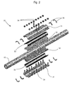
- An example of a repair according to method can be seen in Fig. 2 .
- the method can comprise some or all of the following steps, preferably performed in the order presented below. It is noted that this method make specific reference to birdcage-type failures that occur underwater, but the invention is not necessarily limited to repairing only that type of defect.
- the present invention not only helps eliminate the need to stop the flow line, it also helps eliminate the need to radically section the flexible duct, resulting in discontinuous sections.
- Another advantage that enables the current proposal, beyond its easy assembly, is that it helps eliminate the need to mobilise specific, high cost vessels for several days.
Landscapes
- Engineering & Computer Science (AREA)
- General Engineering & Computer Science (AREA)
- Mechanical Engineering (AREA)
- Pipe Accessories (AREA)
- Lining Or Joining Of Plastics Or The Like (AREA)
- Rigid Pipes And Flexible Pipes (AREA)
Abstract
Description
- The present invention relates to a method to repair flexible flow lines used in the petroleum industry. This method enables the quick repair of a flexible duct displaying a birdcage (BC) type failure without interrupting production flows. The technology proposed, because of its simple characteristics, eliminates the need for replacing the affected section.
- In offshore petroleum production systems, the petroleum produced by wells located on the ocean floor is carried to stationary production units (SPU) using pipes. The set of pipes used to inject water and pump oil and gas is conventionally known as flow lines.
- This set of pipes, which comprises the flow lines, can be basically split into two different types: rigid and flexible, and extend from the producing well to the platform, to which they are connected using support structures especially designed to support and resist the stresses that result both from their own weight and their movement.
- Flexible flow lines may be described as being ducts comprising the overlaying independent layers, often at least six, of different composition: the first and innermost layer is the inner carcass, followed by a polymeric pressure sheath; this is followed by the pressure armour, the internal tensile armour and the external tensile armour, which comprise braided steel wire. Over all of these, there is usually an external polymeric sheath. Other constructions are also possible.
- A preliminary inventory of the applicant's huge industrial estate shows that there are currently some 5,000 kilometres of flexible ducts operating in the different Brazilian sedimentary basins, with diameters ranging from 7 to 45 centimetres.
- Thus, the collection of flexible ducts in Brazil is quite heterogeneous. Different production units have flexible ducts of different diameters and different ages. Added to this scenario, we have the internal pressure caused by the fluids conveyed, the external pressure exerted by the environment, the internal friction between the various layers comprising the duct, corrosion and fatigue. In addition to these, there are all manner of influences caused by the environment in which each structure is assembled, such as marine currents, salinity, changing tides, waves, incrustations with living organisms and external impacts.
- This data demonstrates the value of preventive maintenance techniques and the importance of searching for efficient and quick techniques for corrective maintenance.
- In spite of all the precautions taken to prevent failure, among the failures that can happen is a characteristic phenomenon that is regularly found in flexible ducts, known as birdcaging (illustrated in
Fig. 1 , which shows abirdcage failure 20 on a flexible line 10). This structural failure is the result of, among other factors, sudden and instantaneous depressurising of the duct, which causes radial expansion of the outermost tensile armour through tears in the outer sheath. - Briefly, the failure is due to tears in the outer polymeric sheath, in general associated with the effects caused by said depressurisation of the duct, causing the steel braid lying immediately under it to be exposed to an aggressive medium. Furthermore, the absence of any sheath effect exerted by the outermost polymer layer on the section of duct bearing the tear allows the internal pressure of the duct to push the successive layers in this region outwards, further exposing the steel braid that was uncovered by the tear, thus giving rise to failures that look like a "birdcage" (BC).
- This type of failure not only changes the standard distribution of the stresses along the various layers comprising the flexible duct, it also results in faster action of the aggressive medium on the outer structural steel braid and the polymer layer immediately under it, which are exposed directly to the marine environment.
- Defects such as these seriously compromise the integrity of the line, weakening the wires in the duct structure due to corrosion. Thus, as a safety measure, once a defect is identified it is usually recommended that use of the defective duct be suspended until the damaged section can be replaced with a new one.
- According to current prior art, this is achieved by replacing the damaged section. However, an intervention to replace a section of flexible duct where birdcaging has been detected involves mobilizing special PLSV (Pipe-Laying Support Vessels) and drilling rigs, making the operation quite costly. The intervention also takes a long time, as much as 15 to 16 days.
- One must also consider the availability of special vessels and equipment to perform the repair procedure. Production losses to prepare the line are considerable, and currently there are no alternative methods to correct this type of defect in flexible ducts.
- It is clear that a large petroleum concern requires a technical and administrative structure dedicated to the periodic inspection and correction of sections that are damaged or under imminent risk of leakage. Despite all efforts to this effect, the extension and different types of flexible ducts that comprise the Brazilian industrial park results in a vendor funnel in terms of the availability of the materials required, such as flexible duct sections and connections of a diameter corresponding to the damaged sections. These hurdles can delay such an intervention for months.
- There is a varied history of devices whose purpose is to repair rigid ducts exhibiting some form of wall failure.
- Document
US 5,027,862 of 2 July 1991 refers to basic technology to repair rigid ducts whereby a resin is applied around the duct, encapsulated in a casing. - Document
US 6, 305,719 of 23 October 2001 refers to clamps provided with seals, both two-component, applied around the affected section of a duct, with the possibility of applying some sort of sealant inside the clamps. - Document
US 2004/0129373 of 8 July 2004 describes a method to permanently repair damaged or weakened ducts. The method comprises of removing the rust, the old coating and other undesired surface defects with an abrasive jet. The damaged or weakened surface is then packed in a wrap comprising at least one layer of reinforced composite material. The composite wrap is allowed to cure. If necessary to provide mechanical strength to the affected section of the duct, the affected area is enclosed in sleeves. - Document
US 7,500,494 of 10 March 2009 also refers to a method to repair or reinforce damaged ducts. A layer of fibre is placed around the duct and a clamp is placed around it. Resin is injected so as to permeate the fibres applied. - One can also mention documents such as "The flexible grouted clamp - A novel approach to emergency pipeline repair" by Roland Palmer-Jones, Gordon Paterson and Glenn Aldo Nespeca, presented at the 2011 Pipeline Conference & Exposition. Said paper also discusses attempts to repair ducts, and shows the extent to which this is a contemporary problem, requiring constant research and searching for suitable solutions.
- The present invention was developed with the idea of repairing birdcage-type failures in flexible ducts used in the oil industry, but has wider application to other types of defects too.
- Thus, a method has been developed to repair flexible flow lines using a two-piece clamping collar and a composite material.
- The invention described herein is the result of continuous research in this area, the aim of which is to simplify the procedure currently employed, reducing the time taken for each repair and the overall cost of each intervention. It also aims to provide a new concept in the repair of flexible ducts, whereby the line and its original geometry are maintained, including the wire armour mesh.
- Other advantages this method to repair flexible ducts proposes to deliver are listed below:
- 1. At least partially eliminate the need to interrupt production before or during corrective maintenance;
- 2. At least partially eliminate the need for special PLSVs (Pipe Laying Support Vessels) and drilling rigs;
- 3. At least partially eliminate the need to replace the damaged section;
- 4. At least partially simplify the repair procedure;
- 5. At least partially improve the performance of the damaged line;
- 6. At least partially make each intervention more agile;
- 7. At least partially eliminate the dependence on section and connector vendors.
- According to a first aspect of the present invention there is provided a method for repairing a defect in a flexible flow line, the method characterised by comprising the following steps: providing a two-piece clamping collar; preparing a composite resin; splitting the total volume of composite resin into two, and packing each one in a separate fabric bag, each bag having a warp of natural fibres; attaching a first one of the bags of composite resin to the inside of a first one of the pieces of the two-piece clamping collar, and attaching a second one of the bags of composite resin to the inside of a second one of the pieces of the two-piece clamping collar; placing the two-piece clamping collar around the region of the flexible flow line containing the failure; and securing said two-piece clamping collar with some means of fastening.
- The provision of the resin the natural fibre bags allows for the resin to be transported and positioned on the defect without leakage, and then for the resin to seep through the bags when the collar is fastened and clamped down on the bags around the flexible flow line. Optionally each bag has a weave where the space between threads is in the range of from 0.2 mm to 1.5 mm, and optionally from 0.5 mm to 1.0 mm.
- Optionally the flexible flow line is underwater. The method allows time for the repair to be pre-assembled on land, and then positioned underwater.
- Optionally, the defect is a birdcage-type failure.
- Optionally, preparing the composite resin further comprises dosing the resin with curing agent based on the descent time to the flexible flow line so that, once mixed, the resin will arrive at the flexible flow line sufficiently malleable to penetrate the mesh of the birdcage failure. Optionally, the dosing of the resin is also based on the temperature at the location of the birdcage failure, and/or the depth and and/or pressure at the location of the failure.
- Optionally, the method can further comprise reducing the operating pressure in the line until the birdcage failure contracts, and the defect can be slightly compressed during the step securing said two-piece clamping collar.
- Optionally, the composite resin is a composite epoxy resin reinforced with aramid type synthetic fibres. Optionally the composite resin has a degree of malleability that is equivalent to a consistency between 0.4 and 0.7 N.s/m2, optionally 0.5 and 0.6 N.s/m2, at the temperature at the defect location.
- Optionally, the volume of composite resin used for the repair is at least the volume of the annular space created between the outer wall of the flexible duct and the inside diameter of the two-piece clamping collar to be manufactured, and optionally includes from 20% to 30% more than that volume.
- Optionally, the steps of placing and securing are performed by an ROV (remotely operated vehicle).
- Optionally, the two-piece clamping collar fulfils one or more of the following parameters: being manufactured of steel; having an inside diameter up to 15% larger than the nominal design diameter of the flexible duct in question; being provided with through-holes of up to 10 mm in diameter, optionally up to 6 mm in diameter, arrayed circumferentially around the clamp at intervals of from 40 to 60 mm, optionally 50 mm, along the surface of each half-section of the two-piece clamping collar.
- Optionally, the fastening means is selected from among bolts, jaws and quick-connect devices.
- According to another aspect the invention provides a kit for repairing a defect in a flexible flow line, the kit comprising: a two-piece clamping collar; a composite resin; two fabric bags, each bag having a warp of natural fibres; means for attaching a first one of the bags of composite resin to the inside of a first one of the pieces of the two-piece clamping collar, and attaching a second one of the bags of composite resin to the inside of a second one of the pieces of the two-piece clamping collar; means for fastening for securing said two-piece clamping collar around a defect in a flexible flow line.
- The present invention comprises a method to repair flexible duct, essentially following the steps of: visually inspecting the condition of the outer polymeric layer; determining the dimensions of the failure; determining the depth and temperature where the defect is located, and the descent time; determining the dimensional parameters of the duct to be repaired; cleaning the exposed steel mesh and the surface of the polymer sheath on the section of duct to be repaired; on land, manufacturing the two-piece clamping collar to be used; calculating the volume of epoxy resin required for the repair procedure; preparing the composite resin so that, once it is mixed, it will arrive at the location where it will be applied sufficiently malleable so as to penetrate the birdcage mesh; splitting the total volume of composite resin into two equal volumes, and pack each one in a fabric bag with a warp of natural fibres; attaching each bag of composite resin to the inside of each section of the two-piece clamping collar; placing all of the material in the ROV (Remotely Operated Vehicle); reducing the operating pressure in the line; lowering the two-piece clamping collar with the fabric bags filled with composite resin to the location where the failure is within a pre-determined amount of time; placing the two-piece clamping collar around the section with the failure and attaching it using suitable means.
- A method for repairing a flexible flow line duct using a two-piece clamping collar and composite material, comprises permanently repairing the failure in damaged ducts, applying resin around the damaged area and subsequently placing a two-piece clamping collar around the section, and is characterised by comprising the following steps:
- 1) visually inspecting the state of repair of the outer polymeric layer on site;
- 2) measuring the size of the birdcage failure on site;
- 3) determining the depth and temperature at the location of the defect, and the descent time, preferably concomitantly with step 1 or step 2;
- 4) determining the dimensional parameters of the duct to be repaired, available in the manufacturer's data sheet;
- 5) thoroughly cleaning the exposed steel mesh, as well as the surface of the polymer sheath in the section of duct to be repaired;
- 6) on land and together with step 6, arranging for the manufacture of the two-piece clamping collar to be used, which should meet the following parameters;
- 7) calculating the volume of epoxy resin required for the repair procedure;
- 8) preparing the composite resin before the components are lowered to the location where it will be applied, in such a way that the curing agent is dosed based on the descent time calculated in Step 3, so that once mixed, the resin will arrive at the application location sufficiently malleable to penetrate the birdcage mesh;
- 9) splitting the total volume of composite resin into two equal volumes, and packing each one in a fabric bag with a warp of natural fibres;
- 10) attaching each bag of composite resin to the inside of each section of the two-piece clamping collar;
- 11) placing all of the material in an ROV (Remotely Operated Vehicle);
- 12) reducing the operating pressure in the line until the birdcage failure contracts and the layers before the steel mesh can be slightly compressed;
- 13) lowering the two-piece clamping collar with the fabric bags filled with composite resin to the location of the failure, within the period of time calculated in step 3;
- 14) placing the two-piece clamping collar around the region containing the failure;
- 15) securing said two-piece clamping collar with some means of fastening.
- The method for repairing a flexible flow line duct with a two-piece clamping collar and composite material can be characterised by the fact that the data gathering in steps 1 and 2 may be performed by divers or an ROV, depending on the depth.
- The method for repairing a flexible flow line duct with a two-piece clamping collar and composite material can be characterised by the two-piece clamping collar being manufactured according to the following parameters:
- being preferably manufactured of steel;
- having an inside diameter up to 15% larger than the nominal design diameter of the flexible duct in question;
- being provided with through-holes of up to 6 mm in diameter, arrayed circumferentially around the clamp at intervals of about 50 mm along the surface of each half-section of the two-piece clamping collar;
- having a degree of mechanical resistance that is compatible with the parameters collected in step 4;
- having a length that is compatible with the parameters collected in step 2.
- The method for repairing a flexible flow line duct with a two-piece clamping collar and composite material, can be characterised by the calculation of the volume of composite resin required for the repair being given by the volume of the annular space created between the outer wall of the flexible duct and the inside diameter of the two-piece clamping collar to be manufactured, plus 20 to 30%.
- The method for repairing a flexible flow line duct with a two-piece clamping collar and composite can be characterised by the composite resin having the following minimum characteristics:
- being a composite epoxy resin reinforced with aramid type synthetic fibres;
- having a degree of malleability that is equivalent to a consistency preferably between 0.5 and 0.6 N.s/m2 at the temperature computed in step 3;
- being sufficient to satisfy the volume calculated in step 8.
- The method for repairing a flexible flow line duct with a two-piece clamping collar and composite material can be characterised by the fabric of the bag referenced in
step 10 having a weave where the space between threads is in the range of between 0.5 mm and 1.0 mm. - The method for repairing a flexible flow line duct with a two-piece clamping collar and composite material, can be characterised by the fastening means used in step 15 being selected from among bolts, jaws and quick-connect devices.
- The method for repairing a flexible flow line duct with a two-piece clamping collar and composite material can be characterised by the method being applied preferably to birdcage-type failures.
- The method for repairing a flexible flow line duct with a two-piece clamping collar and composite material can be characterised by the method being applied preferably to flexible ducts.
- The invention is described below, by way of example only, with reference to the accompanying figures, in which:
-
Fig. 1 shows an example of a birdcage-type defect; and -
Fig. 2 shows an example of how a defect can be repaired. - The disclosed method to repair a flexible flow line duct using a two-piece clamping collar and composite material was developed based on research designed primarily to develop alternatives to the corrective procedures currently available, providing the technical team with a method that enables faster intervention in the event of birdcage-type failures in flexible ducts.
- As mentioned above, the existence of birdcage-
type failures 20, as depicted inFig. 1 , normally require reducing the pressure in theduct 10, and consequently the output rate, or even stopping the line altogether. This interference in production lasts until all of the logistics operations currently required to replace defective sections can be completed, causing major delays. - Similar corrective measures using clamps and/or resin are known from prior art, but are all designed for application in rigid ducts. When these methods are applied to correct flexible ducts used to produce crude oil, they to not yield satisfactory results due to a number of specific details and characteristics of the affected components.
- The present invention can provide a method whereby a long-lasting correction can be made to a birdcage-type failure using composite resin and two-piece clamping collars, yielding a result that is both reliable and low cost, and reducing the risk of new failures in the same section once the affected line is back in full and continuous operation.
- Thus the proposed method fulfils parameters such as resistance to the duct's working pressure, providing corrosion protection for the exposed section of line, and keeping this section from moving during the repair. An example of a repair according to method can be seen in
Fig. 2 . The method can comprise some or all of the following steps, preferably performed in the order presented below. It is noted that this method make specific reference to birdcage-type failures that occur underwater, but the invention is not necessarily limited to repairing only that type of defect. - Step 1: Visually inspect the state of repair of the outer polymer sheath of the
flexible line 10 that has the defect, either remotely or not.
It is important to know the extent to which the exposed steel mesh has been structurally compromised, such as the degree of oxidation, the existence of torn wires, incrustations, etc.
The data gathered during this step makes it possible to size the equipment that will be used during the intervention.
This and other on-site data gathering may be done by divers or using an ROV (Remotely Operated Vehicle), depending on the depth. - Step 2: Determine the parameters of the
birdcage failure 20, either remotely or not.
As the industrial estate can be comprised of kilometres of flexible ducts of all sorts of diameters, and diverse operating pressures, it can make more economic sense to manufacture a specific two-piece clamping collar for each failure incident than to keep an inventory of several items with different combinations of diameters, lengths and mechanical resistance.
The dimensional characteristics of thebirdcage 20 contribute to defining the size and extension of the section to be covered by the proposed structural reinforcement, which will also influence the manufacturing parameters for the components that will be used. - Step 3: Preferably together with Step 1 or Step 2, ascertain the depth and temperature at the location of the
defect 20, and the descent time.
These parameters are useful in the calculations for dosing the components of the epoxy resin to be used, and the curing process, so that mixture remains within the viscosity limits that will keep it perfectly malleable until the repair is completed. - Step 4: Determine the hydrostatic test pressure of the
flexible duct 10, normally available in the manufacturer's data sheet.
If this data is not available, an alternative is to use the operating pressure of the flexible duct in the manufacturer's data sheet, and apply a safety factor of e.g. not less than 1.5. - Step 5: Determine the dimensional parameters of the
duct 10 to be repaired, available in the manufacturer's data sheet.
In addition to the data obtained in step 2, also it is useful to know the model and the nominal diameter of theflexible duct 10, which are used as parameters for manufacturing the two-piece clamping collar that will be used for the repair. - Step 6: Thoroughly clean the exposed steel mesh of the flexible duct 10 (i.e. the area of the defect), as well as the surface of the polymer sheath in the section of
duct 10 to be repaired. - Step 7: On land and together with step 6, arrange for the manufacture of the two-
piece clamping collar 31 that will be used, which preferably fulfils some or all of the following parameters:- preferably manufactured of steel.
- having an inside diameter up to 20% larger, optional up to 15% larger than the nominal design diameter of the flexible duct in question.
- being provided with through-holes of up to 10 mm, optionally up to 6 mm in diameter, arrayed circumferentially along the clamp at intervals of around 50 mm, e.g. from 40 mm to 60 mm along the surface of each half-section of the two-piece clamping collar (i.e. arranged along the extent of the collar in the axial direction of the duct).
- having a degree of mechanical resistance that is compatible with the parameters collected in step 4.
- having a length that is compatible with the parameters collected in step 2;
- Step 8: Calculate the volume of composite resin required for the repair procedure.
The total amount of composite (e.g. epoxy) resin to be prepared is at least the volume of the annular space created between the outer wall of the flexible duct and the inside diameter of the two-piece clamping collar to be manufactured, and preferably includes an additional 20 to 30%.
The resin to be prepared shall be split (see later steps) into two, preferably equal parts, packaged inbags 32 and placed on the inside of each section of two-piece clamping collar 31 (that is, oneresin package 32 is placed inside onesection 31, and theother resin package 32 is placed inside the other). When these are placed over theduct failure 20 and joined, the resin will penetrate the steel wire mesh of thebirdcage 20, and the excess will flow out of the ends of the two-piece clamping collar and through small round holes placed in the two-piece clamping collar provided to allow the excess to leave.
Thus, the total volume of composite resin is preferably sufficient to fill the interstices of the failure and the entire perimeter of the section covered by the two-piece clamping collar 31, making sure there are no gaps through which salt water could penetrate into the repair. - Step 9: Prepare the composite resin before all of the components are lowered to the application site, preferably according to one or more of the following parameters:
- a composite epoxy resin reinforced with aramid type synthetic fibres.
- the curing agent shall be dosed according to the descent time calculated in step 3, so that once it is mixed, the resin will arrive at the location where it will be applied with sufficient malleability to penetrate the birdcage mesh. This malleability characteristic is equivalent to a consistency preferably from 0.4 to 0.7 N.s/m2, optionally from 0.5 to 0.6 N.s/m2 at the temperature computed in step 3.
- being sufficient to satisfy the volume calculated in step 8.
- Step 10: Split the total volume of composite resin into two, preferably equal, volumes and pack each one in a
bag 32 made with a warp and weft of natural fibres with a mesh such as to have the space between threads measure on the order of from 0.2 to 1.5 mm, optionally of from 0.5 to 1.0 mm.
If thebag 32 is manufactured of synthetic fibre, because such fibres are continuous, the weft and warp will comprise continuous monofilaments, resulting in a weave where the space between threads is completely empty. This characteristic allows the composite resin to escape through the spaces between the threads during the descent to the work site, resulting in the volume of resin for application being smaller than the amount calculated, and thus compromising the quality of the repair.
On the other hand, if thebags 32 are manufactured of synthetic fibre with a mesh such that the nominal space between threads is less than the proposed 0.2 to 1.2mm (and optionally 0.5 to 1.0 mm), the mesh will hold the composite resin until it reaches the work site. However, in this case the composite resin will be unable to ooze through the mesh efficiently when the two-piece clamping collar is closed around the flexible duct, resulting in resin impregnation gaps between the steel wires that make up thebirdcage 20.
That is,bags 32 of natural fibre have been identified as being particularly effective. As natural fibres are short, it is hypothesised that there will always be fibre-ends protruding from the threads of the warp and weft of the fabric, which tend to project into the gaps between threads, helping to form a barrier for the composite resin as it travels to the work site. However, this additional barrier does not keep the composite resin from oozing through the spaces between the threads when thebag 32 is compressed between the two sections of the two-piece clamping collar and the outer wall of the flexible duct. - Step 11: Attach each
bag 32 of composite resin on the inside of each section of the two-piece clamping collar.
Thebags 32 can be attached to the two-piece clamping collar 31 by tying them with cords using the holes in each section of the two-piece clamping collar. Alternativelyadhesive patches 33 can be used to attach thebags 32 to thecollar 31. - Step 12: Place all of the material in the ROV (Remotely Operated Vehicle).
- Step 13: Reduce the operating pressure in the line until the birdcage failure contracts and the layers before the steel mesh can be slightly compressed.
In this step, the pressure in theline 10 is reduced, but not to zero, as the intact section of theflexible duct 10 will serve as support, opposing the pressure exerted by the two-piece clamping collar sections. If there is no ideal opposing pressure, the composite resin will be unable to extrude from the fabric bag and efficiently impregnate the interstices of the steel wire mesh and the remainingbirdcage failure 20. - Step 14: Lower the two-
piece clamping collar 31 with thefabric bags 32 filled with composite resin to the location where thefailure 20 is, within the period of time calculated in step 3. - Step 15: Place the two-
piece clamping collar 31 around the section with thefailure 20 and attach it using a suitable means 34, such as bolts, jaws or quick connect devices. - Although the steps in the proposed method are well defined for design purposes, to those skilled in the art it will be easy to see that some steps could be performed in a different sequence or simultaneously without affecting the efficiency and the purpose to be attained. Further, the skilled reader will understand that not all steps are essential to the definition of the invention.
- It is easy to see that the present invention not only helps eliminate the need to stop the flow line, it also helps eliminate the need to radically section the flexible duct, resulting in discontinuous sections.
- Another advantage that enables the current proposal, beyond its easy assembly, is that it helps eliminate the need to mobilise specific, high cost vessels for several days.
- In light of such evidence, there is no question that the proposed invention not only helps eliminate direct production losses, but also reduces the cost associated with the logistics of the teams and equipment dedicated to resolving the different birdcage-type incidents that can happen in a large size industrial estate.
- The invention is described herein with reference made to its preferred embodiments. It should be clear however that this invention is not limited to these embodiments, and those skilled in the art will immediately realise that changes and substitutions are possible within the concept of invention described herein.
Claims (14)
- A method for repairing a defect in a flexible flow line, the method characterised by comprising the following steps:providing a two-piece clamping collar;preparing a composite resin;splitting the total volume of composite resin into two, and packing each one in a separate fabric bag, each bag having a warp of natural fibres;attaching a first one of the bags of composite resin to the inside of a first one of the pieces of the two-piece clamping collar, and attaching a second one of the bags of composite resin to the inside of a second one of the pieces of the two-piece clamping collar;placing the two-piece clamping collar around the region of the flexible flow line containing the failure; andsecuring said two-piece clamping collar with some means of fastening.
- The method for repairing a defect in a flexible flow line according to claim 1, wherein each bag has a weave where the space between threads is in the range of from 0.2 mm to 1.5 mm, and optionally from 0.5 mm to 1.0 mm.
- The method for repairing a defect in a flexible flow line according to claim 1 or claim 2, wherein the flexible flow line is underwater.
- The method for repairing a defect in a flexible flow line according to any one of the preceding claims, wherein the defect is a birdcage-type failure.
- The method for repairing a defect in a flexible flow line according to claim 4 when dependent from claim 3, wherein preparing the composite resin further comprises dosing the resin with curing agent based on the descent time to the flexible flow line so that, once mixed, the resin will arrive at the flexible flow line sufficiently malleable to penetrate the mesh of the birdcage failure.
- The method for repairing a defect in a flexible flow line according to claim 5, wherein the dosing of the resin is also based on the temperature at the location of the birdcage failure.
- The method for repairing a defect in a flexible flow line according to claim 4 or any claim dependent therefrom, further comprising reducing the operating pressure in the line until the birdcage failure contracts, and the defect can be slightly compressed during the step securing said two-piece clamping collar.
- The method for repairing a defect in a flexible flow line according to any one of the preceding claims, wherein the composite resin is a composite epoxy resin reinforced with aramid type synthetic fibres.
- The method for repairing a defect in a flexible flow line according to any one of the preceding claims, wherein the composite resin has a degree of malleability that is equivalent to a consistency between 0.4 and 0.7 N.s/m2, optionally 0.5 and 0.6 N.s/m2, at the temperature at the defect location.
- The method for repairing a defect in a flexible flow line according to any one of the preceding claims, wherein volume of composite resin used for the repair is at least the volume of the annular space created between the outer wall of the flexible duct and the inside diameter of the two-piece clamping collar to be manufactured, and optionally includes from 20% to 30% more than that volume.
- The method for repairing a defect in a flexible flow line according to any one of the preceding claims, wherein the steps of placing and securing are performed by an ROV.
- The method for repairing a defect in a flexible flow line according to any one of the preceding claims, wherein by the two-piece clamping collar fulfils one or more of the following parameters:being manufactured of steel;having an inside diameter up to 15% larger than the nominal design diameter of the flexible duct in question;being provided with through-holes of up to 10 mm in diameter, optionally up to 6 mm in diameter, arrayed circumferentially around the clamp at intervals of from 40 to 60 mm, optionally 50 mm, along the surface of each half-section of the two-piece clamping collar.
- The method for repairing a defect in a flexible flow line according to any one of the preceding claims, characterised by the fastening means being selected from among bolts, jaws and quick-connect devices.
- A kit for repairing a defect in a flexible flow line, the kit comprising:a two-piece clamping collar;a composite resin;two fabric bags, each bag having a warp of natural fibres;means for attaching a first one of the bags of composite resin to the inside of a first one of the pieces of the two-piece clamping collar, and attaching a second one of the bags of composite resin to the inside of a second one of the pieces of the two-piece clamping collar;means for fastening for securing said two-piece clamping collar around a defect in a flexible flow line.
Applications Claiming Priority (1)
| Application Number | Priority Date | Filing Date | Title |
|---|---|---|---|
| BR102014002292-9A BR102014002292B1 (en) | 2014-01-30 | 2014-01-30 | Production flexible duct repair method with split clamp and composite material |
Publications (2)
| Publication Number | Publication Date |
|---|---|
| EP2902685A1 true EP2902685A1 (en) | 2015-08-05 |
| EP2902685B1 EP2902685B1 (en) | 2017-01-04 |
Family
ID=52596296
Family Applications (1)
| Application Number | Title | Priority Date | Filing Date |
|---|---|---|---|
| EP15153100.1A Active EP2902685B1 (en) | 2014-01-30 | 2015-01-29 | Method for repairing flexible flow lines with a two-piece clamping collar and composite material |
Country Status (3)
| Country | Link |
|---|---|
| US (1) | US9486969B2 (en) |
| EP (1) | EP2902685B1 (en) |
| BR (1) | BR102014002292B1 (en) |
Cited By (1)
| Publication number | Priority date | Publication date | Assignee | Title |
|---|---|---|---|---|
| WO2019054860A1 (en) * | 2017-09-13 | 2019-03-21 | J. Van Walraven Holding B.V. | Pipe support structure |
Families Citing this family (4)
| Publication number | Priority date | Publication date | Assignee | Title |
|---|---|---|---|---|
| DE102015109785A1 (en) * | 2015-06-18 | 2016-12-22 | Groz-Beckert Kg | Two-dimensional fabric and process for its production |
| BR102017001908A2 (en) | 2017-01-30 | 2018-08-14 | Arbra Engenharia Industrial Ltda | pipeline repair equipment |
| BR102018009604A2 (en) * | 2018-05-11 | 2019-11-26 | Andre Luis De Freitas | METHOD OF USE AND TOOL FOR SEGMENTATION AND SEALING OF GENERAL AND UMBILICAL DUCTS FOR MAINTENANCE AND DECOMMISSIONING OF SUBMARINE LINES |
| BR102018009685A2 (en) * | 2018-05-13 | 2019-11-26 | Gian Marco Zampieron | METHOD OF UNDERWATER INSTALLATION AND UNDERWATER CUTTING AND TERMINATION OF GENERAL AND UMBILICAL DUCTS FOR MAINTENANCE AND DECOMMISSIONING OF SUBMARINE LINES |
Citations (8)
| Publication number | Priority date | Publication date | Assignee | Title |
|---|---|---|---|---|
| US5027862A (en) | 1990-03-15 | 1991-07-02 | Laybourn Bradley K | Hose repair connector apparatus |
| EP0697552A2 (en) * | 1994-08-19 | 1996-02-21 | Petroleo Brasileiro S.A. - Petrobras | Method and equipment for the repair of the outer layer of submarine, flexible piping |
| WO1996019694A1 (en) * | 1993-07-01 | 1996-06-27 | Jens Vatne | Arrangement for use by fitting pipes into each other, and a method for mounting/use of the arrangement |
| US6305719B1 (en) | 1998-10-30 | 2001-10-23 | Laurence S. Smith, Jr. | Pipe repair clamp |
| US20040129373A1 (en) | 2002-09-17 | 2004-07-08 | Nadarajah Nagendran A/L C. | Method and means of repairing a pipe |
| GB2427449A (en) * | 2005-03-18 | 2006-12-27 | Furmanite Internat Ltd | A sealing clamp made of two halves for a pipe |
| GB2442295A (en) * | 2006-07-04 | 2008-04-02 | Rosemary Burgess | Pipe Sleeves |
| US7500494B2 (en) | 2004-12-03 | 2009-03-10 | Illinois Tool Works Inc. | System and method for pipe repair |
Family Cites Families (1)
| Publication number | Priority date | Publication date | Assignee | Title |
|---|---|---|---|---|
| US7367362B2 (en) * | 2004-12-03 | 2008-05-06 | Illinois Tool Works Inc. | System and method for pipe repair |
-
2014
- 2014-01-30 BR BR102014002292-9A patent/BR102014002292B1/en active IP Right Grant
-
2015
- 2015-01-27 US US14/606,484 patent/US9486969B2/en active Active
- 2015-01-29 EP EP15153100.1A patent/EP2902685B1/en active Active
Patent Citations (8)
| Publication number | Priority date | Publication date | Assignee | Title |
|---|---|---|---|---|
| US5027862A (en) | 1990-03-15 | 1991-07-02 | Laybourn Bradley K | Hose repair connector apparatus |
| WO1996019694A1 (en) * | 1993-07-01 | 1996-06-27 | Jens Vatne | Arrangement for use by fitting pipes into each other, and a method for mounting/use of the arrangement |
| EP0697552A2 (en) * | 1994-08-19 | 1996-02-21 | Petroleo Brasileiro S.A. - Petrobras | Method and equipment for the repair of the outer layer of submarine, flexible piping |
| US6305719B1 (en) | 1998-10-30 | 2001-10-23 | Laurence S. Smith, Jr. | Pipe repair clamp |
| US20040129373A1 (en) | 2002-09-17 | 2004-07-08 | Nadarajah Nagendran A/L C. | Method and means of repairing a pipe |
| US7500494B2 (en) | 2004-12-03 | 2009-03-10 | Illinois Tool Works Inc. | System and method for pipe repair |
| GB2427449A (en) * | 2005-03-18 | 2006-12-27 | Furmanite Internat Ltd | A sealing clamp made of two halves for a pipe |
| GB2442295A (en) * | 2006-07-04 | 2008-04-02 | Rosemary Burgess | Pipe Sleeves |
Non-Patent Citations (2)
| Title |
|---|
| ROLAND PALMER-JONES ET AL: "THE FLEXIBLE GROUTED CLAMP - A NOVEL APPROACH TO EMERGENCY PIPELINE REPAIR", RIO PIPELINE CONFERENCE & EXPOSITION 2011, 22 September 2011 (2011-09-22), pages 1 - 13, XP055190072, Retrieved from the Internet <URL:http://www.penspen.com/wp-content/uploads/2014/09/flexible-grouted-clamp.pdf> [retrieved on 20150519] * |
| ROLAND PALMER-JONES; GORDON PATERSON; GLENN ALDO NESPECA: "The flexible grouted clamp - A novel approach to emergency pipeline repair", 2011 PIPELINE CONFERENCE & EXPOSITION, 2011 |
Cited By (4)
| Publication number | Priority date | Publication date | Assignee | Title |
|---|---|---|---|---|
| WO2019054860A1 (en) * | 2017-09-13 | 2019-03-21 | J. Van Walraven Holding B.V. | Pipe support structure |
| NL2019535B1 (en) * | 2017-09-13 | 2019-03-27 | Walraven Holding Bv J Van | Pipe support structure |
| US11098825B2 (en) | 2017-09-13 | 2021-08-24 | J. Van Walraven Holding B.V | Pipe support structure |
| US11506309B2 (en) | 2017-09-13 | 2022-11-22 | J. Van Walraven Holding B.V. | Pipe support structure |
Also Published As
| Publication number | Publication date |
|---|---|
| BR102014002292A2 (en) | 2016-01-05 |
| US9486969B2 (en) | 2016-11-08 |
| US20150210022A1 (en) | 2015-07-30 |
| BR102014002292B1 (en) | 2022-03-29 |
| EP2902685B1 (en) | 2017-01-04 |
Similar Documents
| Publication | Publication Date | Title |
|---|---|---|
| US9486969B2 (en) | Method for repairing flexible flow lines with a two-piece clamping collar and composite material | |
| US5222769A (en) | Double-wall composite pipe and coupling structure assembly | |
| CA2950056C (en) | Repair of pipes | |
| CA2753530C (en) | Improved end connector for high pressure reinforced rubber hose | |
| EP2864748B1 (en) | Assembly and seal test | |
| AU2013260663B2 (en) | Integrity testing | |
| RU2156397C1 (en) | Method of repair of pipe lines (versions) | |
| Eidaninezhad et al. | An overview of marine pipeline repair methods | |
| Lee et al. | Rehabilitation of large diameter prestressed cylinder concrete pipe (PCCP) with FRP composites—Experimental investigation | |
| RU2374551C2 (en) | Method for repair of pipeline defects | |
| RU2619954C1 (en) | Method for repairing concreted portion of underwater pipeline and device for its implementation | |
| CN108253225B (en) | A leak-stopping device for a non-welded oil pipeline | |
| RU2251047C2 (en) | Method of repairing submerged pipeline | |
| RU2805717C1 (en) | Method of cold composite repair by permanent method of through defects in pipelines without changing pumping modes | |
| US20250243755A1 (en) | Pinhole repair method using epoxy and expandable mesh | |
| Lesmana | Use of Clock Spring® as a permanent means of pipeline repair | |
| CN109373102A (en) | A kind of reinforcement that fixture is combined with fibrous composite | |
| Palmer-Jones et al. | The flexible grouted clamp-a novel approach to emergency pipeline repair | |
| Alkhrdaji et al. | PCCP rehabilitation using advanced hybrid FRP composite liner | |
| WO2024253561A1 (en) | Method for the flameless composite repair of through-wall pipeline defects | |
| Ariff et al. | Economic analysis of using E-glass composite wrap repair system for pipelines in Malaysia | |
| Wilson et al. | Fatigue testing of steel pipes repaired with carbon/epoxy composites | |
| EP2268962B1 (en) | Isolation method | |
| Alkhrdaji et al. | Carbon FRP strengthening of PCCP aqueducts | |
| Weller et al. | The Use of Reinforced Thermoplastic Pipe in CO2 Flood Enhanced Oil Recovery |
Legal Events
| Date | Code | Title | Description |
|---|---|---|---|
| PUAI | Public reference made under article 153(3) epc to a published international application that has entered the european phase |
Free format text: ORIGINAL CODE: 0009012 |
|
| 17P | Request for examination filed |
Effective date: 20150129 |
|
| AK | Designated contracting states |
Kind code of ref document: A1 Designated state(s): AL AT BE BG CH CY CZ DE DK EE ES FI FR GB GR HR HU IE IS IT LI LT LU LV MC MK MT NL NO PL PT RO RS SE SI SK SM TR |
|
| AX | Request for extension of the european patent |
Extension state: BA ME |
|
| 17P | Request for examination filed |
Effective date: 20160125 |
|
| RBV | Designated contracting states (corrected) |
Designated state(s): AL AT BE BG CH CY CZ DE DK EE ES FI FR GB GR HR HU IE IS IT LI LT LU LV MC MK MT NL NO PL PT RO RS SE SI SK SM TR |
|
| GRAP | Despatch of communication of intention to grant a patent |
Free format text: ORIGINAL CODE: EPIDOSNIGR1 |
|
| INTG | Intention to grant announced |
Effective date: 20160728 |
|
| GRAS | Grant fee paid |
Free format text: ORIGINAL CODE: EPIDOSNIGR3 |
|
| STAA | Information on the status of an ep patent application or granted ep patent |
Free format text: STATUS: GRANT OF PATENT IS INTENDED |
|
| GRAA | (expected) grant |
Free format text: ORIGINAL CODE: 0009210 |
|
| STAA | Information on the status of an ep patent application or granted ep patent |
Free format text: STATUS: THE PATENT HAS BEEN GRANTED |
|
| AK | Designated contracting states |
Kind code of ref document: B1 Designated state(s): AL AT BE BG CH CY CZ DE DK EE ES FI FR GB GR HR HU IE IS IT LI LT LU LV MC MK MT NL NO PL PT RO RS SE SI SK SM TR |
|
| REG | Reference to a national code |
Ref country code: GB Ref legal event code: FG4D |
|
| REG | Reference to a national code |
Ref country code: CH Ref legal event code: EP |
|
| REG | Reference to a national code |
Ref country code: AT Ref legal event code: REF Ref document number: 859587 Country of ref document: AT Kind code of ref document: T Effective date: 20170115 |
|
| REG | Reference to a national code |
Ref country code: IE Ref legal event code: FG4D |
|
| REG | Reference to a national code |
Ref country code: DE Ref legal event code: R096 Ref document number: 602015001159 Country of ref document: DE |
|
| REG | Reference to a national code |
Ref country code: NO Ref legal event code: T2 Effective date: 20170104 |
|
| REG | Reference to a national code |
Ref country code: NL Ref legal event code: MP Effective date: 20170104 Ref country code: LT Ref legal event code: MG4D |
|
| PG25 | Lapsed in a contracting state [announced via postgrant information from national office to epo] |
Ref country code: BE Free format text: LAPSE BECAUSE OF NON-PAYMENT OF DUE FEES Effective date: 20170131 |
|
| REG | Reference to a national code |
Ref country code: AT Ref legal event code: MK05 Ref document number: 859587 Country of ref document: AT Kind code of ref document: T Effective date: 20170104 |
|
| PG25 | Lapsed in a contracting state [announced via postgrant information from national office to epo] |
Ref country code: NL Free format text: LAPSE BECAUSE OF FAILURE TO SUBMIT A TRANSLATION OF THE DESCRIPTION OR TO PAY THE FEE WITHIN THE PRESCRIBED TIME-LIMIT Effective date: 20170104 |
|
| PG25 | Lapsed in a contracting state [announced via postgrant information from national office to epo] |
Ref country code: FI Free format text: LAPSE BECAUSE OF FAILURE TO SUBMIT A TRANSLATION OF THE DESCRIPTION OR TO PAY THE FEE WITHIN THE PRESCRIBED TIME-LIMIT Effective date: 20170104 Ref country code: LT Free format text: LAPSE BECAUSE OF FAILURE TO SUBMIT A TRANSLATION OF THE DESCRIPTION OR TO PAY THE FEE WITHIN THE PRESCRIBED TIME-LIMIT Effective date: 20170104 Ref country code: GR Free format text: LAPSE BECAUSE OF FAILURE TO SUBMIT A TRANSLATION OF THE DESCRIPTION OR TO PAY THE FEE WITHIN THE PRESCRIBED TIME-LIMIT Effective date: 20170405 Ref country code: IS Free format text: LAPSE BECAUSE OF FAILURE TO SUBMIT A TRANSLATION OF THE DESCRIPTION OR TO PAY THE FEE WITHIN THE PRESCRIBED TIME-LIMIT Effective date: 20170504 Ref country code: HR Free format text: LAPSE BECAUSE OF FAILURE TO SUBMIT A TRANSLATION OF THE DESCRIPTION OR TO PAY THE FEE WITHIN THE PRESCRIBED TIME-LIMIT Effective date: 20170104 |
|
| REG | Reference to a national code |
Ref country code: DE Ref legal event code: R119 Ref document number: 602015001159 Country of ref document: DE |
|
| PG25 | Lapsed in a contracting state [announced via postgrant information from national office to epo] |
Ref country code: RS Free format text: LAPSE BECAUSE OF FAILURE TO SUBMIT A TRANSLATION OF THE DESCRIPTION OR TO PAY THE FEE WITHIN THE PRESCRIBED TIME-LIMIT Effective date: 20170104 Ref country code: PL Free format text: LAPSE BECAUSE OF FAILURE TO SUBMIT A TRANSLATION OF THE DESCRIPTION OR TO PAY THE FEE WITHIN THE PRESCRIBED TIME-LIMIT Effective date: 20170104 Ref country code: AT Free format text: LAPSE BECAUSE OF FAILURE TO SUBMIT A TRANSLATION OF THE DESCRIPTION OR TO PAY THE FEE WITHIN THE PRESCRIBED TIME-LIMIT Effective date: 20170104 Ref country code: SE Free format text: LAPSE BECAUSE OF FAILURE TO SUBMIT A TRANSLATION OF THE DESCRIPTION OR TO PAY THE FEE WITHIN THE PRESCRIBED TIME-LIMIT Effective date: 20170104 Ref country code: ES Free format text: LAPSE BECAUSE OF FAILURE TO SUBMIT A TRANSLATION OF THE DESCRIPTION OR TO PAY THE FEE WITHIN THE PRESCRIBED TIME-LIMIT Effective date: 20170104 Ref country code: BG Free format text: LAPSE BECAUSE OF FAILURE TO SUBMIT A TRANSLATION OF THE DESCRIPTION OR TO PAY THE FEE WITHIN THE PRESCRIBED TIME-LIMIT Effective date: 20170404 Ref country code: PT Free format text: LAPSE BECAUSE OF FAILURE TO SUBMIT A TRANSLATION OF THE DESCRIPTION OR TO PAY THE FEE WITHIN THE PRESCRIBED TIME-LIMIT Effective date: 20170504 Ref country code: LV Free format text: LAPSE BECAUSE OF FAILURE TO SUBMIT A TRANSLATION OF THE DESCRIPTION OR TO PAY THE FEE WITHIN THE PRESCRIBED TIME-LIMIT Effective date: 20170104 |
|
| PG25 | Lapsed in a contracting state [announced via postgrant information from national office to epo] |
Ref country code: CZ Free format text: LAPSE BECAUSE OF FAILURE TO SUBMIT A TRANSLATION OF THE DESCRIPTION OR TO PAY THE FEE WITHIN THE PRESCRIBED TIME-LIMIT Effective date: 20170104 Ref country code: SK Free format text: LAPSE BECAUSE OF FAILURE TO SUBMIT A TRANSLATION OF THE DESCRIPTION OR TO PAY THE FEE WITHIN THE PRESCRIBED TIME-LIMIT Effective date: 20170104 Ref country code: RO Free format text: LAPSE BECAUSE OF FAILURE TO SUBMIT A TRANSLATION OF THE DESCRIPTION OR TO PAY THE FEE WITHIN THE PRESCRIBED TIME-LIMIT Effective date: 20170104 Ref country code: EE Free format text: LAPSE BECAUSE OF FAILURE TO SUBMIT A TRANSLATION OF THE DESCRIPTION OR TO PAY THE FEE WITHIN THE PRESCRIBED TIME-LIMIT Effective date: 20170104 Ref country code: IT Free format text: LAPSE BECAUSE OF FAILURE TO SUBMIT A TRANSLATION OF THE DESCRIPTION OR TO PAY THE FEE WITHIN THE PRESCRIBED TIME-LIMIT Effective date: 20170104 |
|
| REG | Reference to a national code |
Ref country code: IE Ref legal event code: MM4A |
|
| PLBE | No opposition filed within time limit |
Free format text: ORIGINAL CODE: 0009261 |
|
| STAA | Information on the status of an ep patent application or granted ep patent |
Free format text: STATUS: NO OPPOSITION FILED WITHIN TIME LIMIT |
|
| PG25 | Lapsed in a contracting state [announced via postgrant information from national office to epo] |
Ref country code: DK Free format text: LAPSE BECAUSE OF FAILURE TO SUBMIT A TRANSLATION OF THE DESCRIPTION OR TO PAY THE FEE WITHIN THE PRESCRIBED TIME-LIMIT Effective date: 20170104 Ref country code: DE Free format text: LAPSE BECAUSE OF NON-PAYMENT OF DUE FEES Effective date: 20170801 Ref country code: MC Free format text: LAPSE BECAUSE OF FAILURE TO SUBMIT A TRANSLATION OF THE DESCRIPTION OR TO PAY THE FEE WITHIN THE PRESCRIBED TIME-LIMIT Effective date: 20170104 Ref country code: LU Free format text: LAPSE BECAUSE OF NON-PAYMENT OF DUE FEES Effective date: 20170129 Ref country code: SM Free format text: LAPSE BECAUSE OF FAILURE TO SUBMIT A TRANSLATION OF THE DESCRIPTION OR TO PAY THE FEE WITHIN THE PRESCRIBED TIME-LIMIT Effective date: 20170104 |
|
| REG | Reference to a national code |
Ref country code: FR Ref legal event code: ST Effective date: 20171108 |
|
| PG25 | Lapsed in a contracting state [announced via postgrant information from national office to epo] |
Ref country code: FR Free format text: LAPSE BECAUSE OF NON-PAYMENT OF DUE FEES Effective date: 20170306 |
|
| REG | Reference to a national code |
Ref country code: BE Ref legal event code: MM Effective date: 20170131 |
|
| PG25 | Lapsed in a contracting state [announced via postgrant information from national office to epo] |
Ref country code: SI Free format text: LAPSE BECAUSE OF FAILURE TO SUBMIT A TRANSLATION OF THE DESCRIPTION OR TO PAY THE FEE WITHIN THE PRESCRIBED TIME-LIMIT Effective date: 20170104 Ref country code: IE Free format text: LAPSE BECAUSE OF NON-PAYMENT OF DUE FEES Effective date: 20170129 |
|
| REG | Reference to a national code |
Ref country code: CH Ref legal event code: PL |
|
| PG25 | Lapsed in a contracting state [announced via postgrant information from national office to epo] |
Ref country code: MT Free format text: LAPSE BECAUSE OF NON-PAYMENT OF DUE FEES Effective date: 20170129 |
|
| PG25 | Lapsed in a contracting state [announced via postgrant information from national office to epo] |
Ref country code: LI Free format text: LAPSE BECAUSE OF NON-PAYMENT OF DUE FEES Effective date: 20180131 Ref country code: CH Free format text: LAPSE BECAUSE OF NON-PAYMENT OF DUE FEES Effective date: 20180131 |
|
| PG25 | Lapsed in a contracting state [announced via postgrant information from national office to epo] |
Ref country code: HU Free format text: LAPSE BECAUSE OF FAILURE TO SUBMIT A TRANSLATION OF THE DESCRIPTION OR TO PAY THE FEE WITHIN THE PRESCRIBED TIME-LIMIT; INVALID AB INITIO Effective date: 20150129 |
|
| PG25 | Lapsed in a contracting state [announced via postgrant information from national office to epo] |
Ref country code: CY Free format text: LAPSE BECAUSE OF FAILURE TO SUBMIT A TRANSLATION OF THE DESCRIPTION OR TO PAY THE FEE WITHIN THE PRESCRIBED TIME-LIMIT Effective date: 20170104 |
|
| PG25 | Lapsed in a contracting state [announced via postgrant information from national office to epo] |
Ref country code: MK Free format text: LAPSE BECAUSE OF FAILURE TO SUBMIT A TRANSLATION OF THE DESCRIPTION OR TO PAY THE FEE WITHIN THE PRESCRIBED TIME-LIMIT Effective date: 20170104 |
|
| PG25 | Lapsed in a contracting state [announced via postgrant information from national office to epo] |
Ref country code: TR Free format text: LAPSE BECAUSE OF FAILURE TO SUBMIT A TRANSLATION OF THE DESCRIPTION OR TO PAY THE FEE WITHIN THE PRESCRIBED TIME-LIMIT Effective date: 20170104 |
|
| PG25 | Lapsed in a contracting state [announced via postgrant information from national office to epo] |
Ref country code: AL Free format text: LAPSE BECAUSE OF FAILURE TO SUBMIT A TRANSLATION OF THE DESCRIPTION OR TO PAY THE FEE WITHIN THE PRESCRIBED TIME-LIMIT Effective date: 20170104 |
|
| P01 | Opt-out of the competence of the unified patent court (upc) registered |
Effective date: 20230627 |
|
| PGFP | Annual fee paid to national office [announced via postgrant information from national office to epo] |
Ref country code: GB Payment date: 20251217 Year of fee payment: 12 |
|
| PGFP | Annual fee paid to national office [announced via postgrant information from national office to epo] |
Ref country code: NO Payment date: 20260128 Year of fee payment: 12 |