EP2902652A1 - Automatic transmission and automatic-transmission control method - Google Patents
Automatic transmission and automatic-transmission control method Download PDFInfo
- Publication number
- EP2902652A1 EP2902652A1 EP13842398.3A EP13842398A EP2902652A1 EP 2902652 A1 EP2902652 A1 EP 2902652A1 EP 13842398 A EP13842398 A EP 13842398A EP 2902652 A1 EP2902652 A1 EP 2902652A1
- Authority
- EP
- European Patent Office
- Prior art keywords
- pressure
- mode
- friction element
- release
- oil chamber
- Prior art date
- Legal status (The legal status is an assumption and is not a legal conclusion. Google has not performed a legal analysis and makes no representation as to the accuracy of the status listed.)
- Withdrawn
Links
Images


Classifications
-
- F—MECHANICAL ENGINEERING; LIGHTING; HEATING; WEAPONS; BLASTING
- F16—ENGINEERING ELEMENTS AND UNITS; GENERAL MEASURES FOR PRODUCING AND MAINTAINING EFFECTIVE FUNCTIONING OF MACHINES OR INSTALLATIONS; THERMAL INSULATION IN GENERAL
- F16H—GEARING
- F16H61/00—Control functions within control units of change-speed- or reversing-gearings for conveying rotary motion ; Control of exclusively fluid gearing, friction gearing, gearings with endless flexible members or other particular types of gearing
- F16H61/0021—Generation or control of line pressure
-
- F—MECHANICAL ENGINEERING; LIGHTING; HEATING; WEAPONS; BLASTING
- F16—ENGINEERING ELEMENTS AND UNITS; GENERAL MEASURES FOR PRODUCING AND MAINTAINING EFFECTIVE FUNCTIONING OF MACHINES OR INSTALLATIONS; THERMAL INSULATION IN GENERAL
- F16D—COUPLINGS FOR TRANSMITTING ROTATION; CLUTCHES; BRAKES
- F16D23/00—Details of mechanically-actuated clutches not specific for one distinct type
- F16D23/12—Mechanical clutch-actuating mechanisms arranged outside the clutch as such
-
- F—MECHANICAL ENGINEERING; LIGHTING; HEATING; WEAPONS; BLASTING
- F16—ENGINEERING ELEMENTS AND UNITS; GENERAL MEASURES FOR PRODUCING AND MAINTAINING EFFECTIVE FUNCTIONING OF MACHINES OR INSTALLATIONS; THERMAL INSULATION IN GENERAL
- F16D—COUPLINGS FOR TRANSMITTING ROTATION; CLUTCHES; BRAKES
- F16D25/00—Fluid-actuated clutches
- F16D25/06—Fluid-actuated clutches in which the fluid actuates a piston incorporated in, i.e. rotating with the clutch
- F16D25/062—Fluid-actuated clutches in which the fluid actuates a piston incorporated in, i.e. rotating with the clutch the clutch having friction surfaces
- F16D25/063—Fluid-actuated clutches in which the fluid actuates a piston incorporated in, i.e. rotating with the clutch the clutch having friction surfaces with clutch members exclusively moving axially
- F16D25/0635—Fluid-actuated clutches in which the fluid actuates a piston incorporated in, i.e. rotating with the clutch the clutch having friction surfaces with clutch members exclusively moving axially with flat friction surfaces, e.g. discs
- F16D25/0638—Fluid-actuated clutches in which the fluid actuates a piston incorporated in, i.e. rotating with the clutch the clutch having friction surfaces with clutch members exclusively moving axially with flat friction surfaces, e.g. discs with more than two discs, e.g. multiple lamellae
-
- F—MECHANICAL ENGINEERING; LIGHTING; HEATING; WEAPONS; BLASTING
- F16—ENGINEERING ELEMENTS AND UNITS; GENERAL MEASURES FOR PRODUCING AND MAINTAINING EFFECTIVE FUNCTIONING OF MACHINES OR INSTALLATIONS; THERMAL INSULATION IN GENERAL
- F16D—COUPLINGS FOR TRANSMITTING ROTATION; CLUTCHES; BRAKES
- F16D25/00—Fluid-actuated clutches
- F16D25/12—Details not specific to one of the before-mentioned types
-
- F—MECHANICAL ENGINEERING; LIGHTING; HEATING; WEAPONS; BLASTING
- F16—ENGINEERING ELEMENTS AND UNITS; GENERAL MEASURES FOR PRODUCING AND MAINTAINING EFFECTIVE FUNCTIONING OF MACHINES OR INSTALLATIONS; THERMAL INSULATION IN GENERAL
- F16D—COUPLINGS FOR TRANSMITTING ROTATION; CLUTCHES; BRAKES
- F16D48/00—External control of clutches
- F16D48/02—Control by fluid pressure
-
- F—MECHANICAL ENGINEERING; LIGHTING; HEATING; WEAPONS; BLASTING
- F16—ENGINEERING ELEMENTS AND UNITS; GENERAL MEASURES FOR PRODUCING AND MAINTAINING EFFECTIVE FUNCTIONING OF MACHINES OR INSTALLATIONS; THERMAL INSULATION IN GENERAL
- F16H—GEARING
- F16H61/00—Control functions within control units of change-speed- or reversing-gearings for conveying rotary motion ; Control of exclusively fluid gearing, friction gearing, gearings with endless flexible members or other particular types of gearing
- F16H61/12—Detecting malfunction or potential malfunction, e.g. fail safe ; Circumventing or fixing failures
-
- F—MECHANICAL ENGINEERING; LIGHTING; HEATING; WEAPONS; BLASTING
- F16—ENGINEERING ELEMENTS AND UNITS; GENERAL MEASURES FOR PRODUCING AND MAINTAINING EFFECTIVE FUNCTIONING OF MACHINES OR INSTALLATIONS; THERMAL INSULATION IN GENERAL
- F16H—GEARING
- F16H63/00—Control outputs from the control unit to change-speed- or reversing-gearings for conveying rotary motion or to other devices than the final output mechanism
- F16H63/02—Final output mechanisms therefor; Actuating means for the final output mechanisms
- F16H63/30—Constructional features of the final output mechanisms
- F16H63/3023—Constructional features of the final output mechanisms the final output mechanisms comprising elements moved by fluid pressure
- F16H63/3026—Constructional features of the final output mechanisms the final output mechanisms comprising elements moved by fluid pressure comprising friction clutches or brakes
-
- F—MECHANICAL ENGINEERING; LIGHTING; HEATING; WEAPONS; BLASTING
- F16—ENGINEERING ELEMENTS AND UNITS; GENERAL MEASURES FOR PRODUCING AND MAINTAINING EFFECTIVE FUNCTIONING OF MACHINES OR INSTALLATIONS; THERMAL INSULATION IN GENERAL
- F16D—COUPLINGS FOR TRANSMITTING ROTATION; CLUTCHES; BRAKES
- F16D48/00—External control of clutches
- F16D48/02—Control by fluid pressure
- F16D2048/0212—Details of pistons for primary or secondary cylinders especially adapted for fluid control
-
- F—MECHANICAL ENGINEERING; LIGHTING; HEATING; WEAPONS; BLASTING
- F16—ENGINEERING ELEMENTS AND UNITS; GENERAL MEASURES FOR PRODUCING AND MAINTAINING EFFECTIVE FUNCTIONING OF MACHINES OR INSTALLATIONS; THERMAL INSULATION IN GENERAL
- F16H—GEARING
- F16H61/00—Control functions within control units of change-speed- or reversing-gearings for conveying rotary motion ; Control of exclusively fluid gearing, friction gearing, gearings with endless flexible members or other particular types of gearing
- F16H61/12—Detecting malfunction or potential malfunction, e.g. fail safe ; Circumventing or fixing failures
- F16H2061/1256—Detecting malfunction or potential malfunction, e.g. fail safe ; Circumventing or fixing failures characterised by the parts or units where malfunctioning was assumed or detected
- F16H2061/1288—Detecting malfunction or potential malfunction, e.g. fail safe ; Circumventing or fixing failures characterised by the parts or units where malfunctioning was assumed or detected the failing part is an actuator
-
- F—MECHANICAL ENGINEERING; LIGHTING; HEATING; WEAPONS; BLASTING
- F16—ENGINEERING ELEMENTS AND UNITS; GENERAL MEASURES FOR PRODUCING AND MAINTAINING EFFECTIVE FUNCTIONING OF MACHINES OR INSTALLATIONS; THERMAL INSULATION IN GENERAL
- F16H—GEARING
- F16H63/00—Control outputs from the control unit to change-speed- or reversing-gearings for conveying rotary motion or to other devices than the final output mechanism
- F16H63/02—Final output mechanisms therefor; Actuating means for the final output mechanisms
- F16H63/30—Constructional features of the final output mechanisms
- F16H63/3023—Constructional features of the final output mechanisms the final output mechanisms comprising elements moved by fluid pressure
- F16H63/3026—Constructional features of the final output mechanisms the final output mechanisms comprising elements moved by fluid pressure comprising friction clutches or brakes
- F16H2063/303—Constructional features of the final output mechanisms the final output mechanisms comprising elements moved by fluid pressure comprising friction clutches or brakes the friction member is actuated and released by applying pressure to different fluid chambers
-
- F—MECHANICAL ENGINEERING; LIGHTING; HEATING; WEAPONS; BLASTING
- F16—ENGINEERING ELEMENTS AND UNITS; GENERAL MEASURES FOR PRODUCING AND MAINTAINING EFFECTIVE FUNCTIONING OF MACHINES OR INSTALLATIONS; THERMAL INSULATION IN GENERAL
- F16H—GEARING
- F16H63/00—Control outputs from the control unit to change-speed- or reversing-gearings for conveying rotary motion or to other devices than the final output mechanism
- F16H63/02—Final output mechanisms therefor; Actuating means for the final output mechanisms
- F16H63/30—Constructional features of the final output mechanisms
- F16H63/34—Locking or disabling mechanisms
Definitions
- the present invention relates to an automatic transmission and a control method of an automatic transmission.
- JP7-12221A uses a friction element operated by a hydraulic pressure in order to couple two members (in a case of a clutch, both are rotating elements, while in a case of a brake, one is a rotating element and the other is a non-rotating element) arranged coaxially as a clutch brake of an automatic transmission.
- a plurality of friction plates are mounted on each of the two members slidably in an axial direction, and the friction plates of the two members are arranged alternately, for example.
- a hydraulic pressure needs to be continuously supplied to the hydraulic piston by operating a hydraulic pump in order to maintain a engaged state, which causes a problem of deterioration of a fuel cost of a vehicle on which the automatic transmission is mounted.
- an automatic transmission it can be configured such that when the friction element is to be released, a release pressure is supplied so that the lock mechanism is unlocked, and the hydraulic piston is moved to a predetermined position so as to release the friction element.
- the present invention was made in order to solve such problems and has an object to solve fixation of the hydraulic piston and to reliably release the friction element even if the hydraulic piston is fixed when the friction element is released.
- An automatic transmission is an automatic transmission arranged in a power transmission path and having a friction element in which, when an ON pressure is supplied to a engaging-side oil chamber, the hydraulic piston is moved and engaged and a lock mechanism enters a lock state, when the lock mechanism enters the lock state, a engaged state is maintained even if a hydraulic pressure of the engaging-side oil chamber is lowered, and when an OFF pressure is supplied to a release-side oil chamber when the lock mechanism is in the lock state, the lock mechanism enters an unlock state, the hydraulic piston is moved and released, and a release state is maintained even if the hydraulic pressure of the release-side oil chamber is lowered, provided with a hydraulic control unit configured to be controllable the ON pressure and the OFF pressure, a mode selection unit configured to be selectable a mode for engaging the friction element or a mode for releasing the friction element as a mode of the automatic transmission, and a release-state detection unit configured to detect whether or not the friction element has been released when the mode for releasing the friction element
- a control method of an automatic transmission is a control method of an automatic transmission for controlling the automatic transmission arranged in a power transmission path and having a friction element in which, when an ON pressure is supplied to a engaging-side oil chamber, the hydraulic piston is moved and engaged and a lock mechanism enters a lock state, when the lock mechanism enters the lock state, a engaged state is maintained even if a hydraulic pressure of the engaging-side oil chamber is lowered, and when an OFF pressure is supplied to a release-side oil chamber when the lock mechanism is in the lock state, the lock mechanism enters an unlock state, the hydraulic piston is moved and released, and a release state is maintained even if the hydraulic pressure of the release-side oil chamber is lowered, in which whether a mode of the automatic transmission is a mode for engaging the friction element or a mode for releasing the friction element is detected, when the mode of the automatic transmission is changed from the mode for engaging the friction element to the mode for releasing the friction element and the OFF pressure is supplied to the release-side oil chamber, whether
- the friction element can be reliably released by supplying the OFF pressure again.
- Fig. 1 illustrates a schematic configuration of a vehicle provided with an automatic transmission according to the embodiment of the present invention.
- the vehicle includes an engine 1, a torque converter 2, and a transmission 3, and output rotation of the engine 1 is transmitted to a driving wheel, not shown, through the torque converter 2, the transmission 3, and a differential gear unit, not shown.
- the transmission 3 is a stepped or non-stage automatic transmission.
- the transmission 3 includes a reverse brake 4 and a forward clutch 5.
- the transmission 3 reverses rotation of the engine 1 and outputs it in a state in which the reverse brake 4 is engaged, while the rotation of the engine 1 is outputted while a rotation direction is maintained in a state in which the forward clutch 5 is engaged.
- the reverse brake 4 is a prior-art friction element which is engaged by supplying an engaging pressure, and the engaging pressure needs to be continuously supplied in order to maintain the engaged state. It is only necessary to stop supply of the engaging pressure to release the reverse brake 4.
- the forward clutch 5 is a friction element provided with a lock mechanism BL as will be described later. If an ON pressure is supplied to the forward clutch 5 and the lock mechanism BL enters a lock state, the forward clutch 5 can maintain the engaged state even if the supply of the ON pressure is stopped. In order to release the forward clutch 5, it is only necessary to supply an OFF pressure to the forward clutch 5 so as to bring the lock mechanism BL into a release state, and once the lock mechanism BL enters the release state, the forward clutch 5 can maintain the release state even if the supply of the OFF pressure is stopped. A configuration of the forward clutch 5 will be described later in detail.
- the hydraulic control circuit 7 includes a regulator valve for regulating a hydraulic pressure from a hydraulic pump 8 driven by the engine 1 to a line pressure, a solenoid valve for regulating a hydraulic pressure to be supplied to the friction element (if the transmission 3 is a continuously variable transmission, a constituent element of the continuously variable transmission mechanism in addition) including the forward clutch 5 with a line pressure as a source pressure, and an oil path connecting the hydraulic pump 8, each valve and each friction element.
- Each valve of the hydraulic control circuit 7 is controlled on the basis of a control signal from a transmission controller 9.
- the transmission controller 9 is constituted by a CPU, a ROM, a RAM, an input/output interface and the like, determines a running state of the vehicle on the basis of various signals inputted from various sensors and an engine controller and outputs an instruction to the hydraulic control circuit 7 so that a gear position (a speed ratio if the transmission 3 is the continuously variable transmission) suitable for the running state is realized.
- a rotation speed sensor 101 for detecting a rotation speed Ne of the engine 1 signals and the like from a rotation speed sensor 101 for detecting a rotation speed Ne of the engine 1, a rotation speed sensor 102 for detecting an input rotation speed of the transmission 3, a rotation speed sensor 103 for detecting an output rotation speed of the transmission 3, a mode detection switch 104 for detecting a mode of the transmission 3 selected by a select switch 11, an accelerator opening-degree sensor 105 for detecting an operation amount of an accelerator pedal (hereinafter referred to as an "accelerator opening-degree APO"), a brake switch 106 for detecting ON/OFF of the brake, a G sensor 107 for detecting acceleration/ deceleration of the vehicle and the like are inputted.
- an accelerator opening-degree sensor 105 for detecting an operation amount of an accelerator pedal (hereinafter referred to as an "accelerator opening-degree APO")
- a brake switch 106 for detecting ON/OFF of the brake
- a G sensor 107 for detecting acceleration/ deceler
- the select switch 11 is a lever type or a button type and is capable of selecting any one of modes, that is, a parking mode (hereinafter referred to as a "P mode”), a reverse mode (hereinafter referred to as an "R mode”), a neutral mode (hereinafter referred to as an "N mode”), and a drive mode (hereinafter referred to as a "D mode”) as the mode of the transmission 3 by operating the lever or the button.
- P mode parking mode
- R mode reverse mode
- N mode neutral mode
- D mode drive mode
- the transmission controller 9 engages or releases the reverse brake 4 and the forward clutch 5, respectively, in response to the mode selected by the select switch 11. Specifically, in the D mode, the reverse brake 4 is released, and the forward clutch 5 is engaged. In the R mode, the reverse brake 4 is engaged, and the forward clutch 5 is released. In the P mode and the N mode, the reverse brake 4 and the forward clutch 5 are released.
- Fig. 2 illustrates sections of the forward clutch 5 and a clutch operation pack 6 for operating this. Each configuration will be described below.
- the forward clutch 5 includes a clutch drum 51, a clutch hub 52, a driven plate 53, a drive plate 54, and a retainer plate 55.
- the clutch drum 51 and the clutch hub 52 are arranged coaxially. To the clutch drum 51, a rotating element (shaft, gear and the like), not shown, is coupled. To the clutch hub 52, another rotating element (shaft, gear and the like), not shown, is coupled.
- the driven plate 53 is mounted by spline coupling slidably in the axial direction.
- the drive plate 54 is mounted by spline coupling slidably in the axial direction.
- Four pieces of the driven plates 53 and four pieces of the drive plates 54 are arranged alternately, and clutch facing is bonded on friction surfaces on both sides of the drive plates 54.
- the clutch drum 51 transmits rotation inputted from the rotating element coupled to the clutch drum 51 to the clutch hub 52 through the driven plate 53 and the drive plate 54.
- the retainer plate 55 is interposed between the drive plate 54 arranged on an end portion on a side opposite to the hydraulic piston 61 and a snap ring 64 fixed to a groove in an inner periphery of the clutch drum 51.
- One of surfaces of the retainer plate 55 is the friction surface.
- the retainer plate 55 has a thickness in the axial direction larger than that of the driven plate 53 and prevents falling-down of the driven plate 53 and the drive plate 54.
- the clutch operation pack 6 includes the hydraulic piston 61, an ON pressure piston chamber 62, an OFF pressure piston chamber 63, a snap ring 64, a diaphragm spring 65, a partition plate 66, and the lock mechanism BL.
- the hydraulic piston 61 is arranged capable of displacement in the axial direction with respect to the forward clutch 5.
- One of the surfaces of the hydraulic piston 61 is an ON pressure receiving surface 61a, and the other surface is an OFF pressure receiving surface 61b.
- the ON pressure piston chamber 62 is defined between the clutch drum 51 and the hydraulic piston 61 in order to have an ON pressure act on the ON pressure receiving surface 61a of the hydraulic piston 61.
- the OFF pressure piston chamber 63 is defined between the partition plate 66 fixed to the clutch drum 51 and the hydraulic piston 61 in order to have an OFF pressure act on the OFF pressure receiving surface 61b of the hydraulic piston 61.
- the snap ring 64 is arranged at a position on a side opposite to the hydraulic piston 61 sandwiching the forward clutch 5 between them and supports the forward clutch 5 in the axial direction.
- the diaphragm spring 65 is interposed between a clutch-side end surface 61 c of the hydraulic piston 61 and a piston-side end surface 5a of the forward clutch 5. Two pieces of the diaphragm springs 65 are arranged by being stacked in the axial direction, and when the hydraulic piston 61 is moved in an engaging direction toward the snap ring 64, an engaging force is made to act on the forward clutch 5.
- the lock mechanism BL is built in the clutch drum 51 and is constituted by the hydraulic piston 61, a ball holding piston 67, and a ball 68.
- the hydraulic piston 61 is arranged capable of displacement in the axial direction with respect to the forward clutch 5.
- an accommodating portion 61 d and a taper surface 61 e are provided on the hydraulic piston 61.
- the accommodating portion 61d accommodates the ball 68 when movement of the hydraulic piston 61 in a release direction is regulated.
- the taper surface 61e is formed continuously to the accommodating portion 61 d and it pushes the ball 68 into the inside when the hydraulic piston 61 makes a stroke in the release direction.
- the ball holding piston 67 is arranged in a cylindrical space defined by an inner-peripheral cylindrical portion 51a of the clutch drum 51 covering the hydraulic piston 61 and a partition cylindrical wall portion 51 b protruding in the axial direction from the clutch drum 51.
- the ball holding piston 67 moves in the axial direction when the ON pressure or the OFF pressure acts.
- a space between an outer peripheral surface of the ball holding piston 67 and the partition cylindrical wall portion 51b is sealed by a seal ring 84, a space between an inner peripheral surface of the ball holding piston 67 and the inner-peripheral cylindrical portion 51a is sealed by a seal ring 85, and a space between an inner peripheral surface of the hydraulic piston 61 and the partition cylindrical wall portion 51b is sealed by a seal ring 86.
- the ON pressure piston chamber 62 and the OFF pressure piston chamber 63 are defined on both sides of the hydraulic piston 61.
- an accommodating portion 67c accommodates the ball 68 when movement of the hydraulic piston 61 in the release direction is allowed.
- the taper surface 67d and the lock surface 67e are formed continuously to the accommodating portion 67c, and when the ball holding piston 67 makes a stroke toward the forward clutch 5, the taper surface 67d pushes out the ball 68 to an outside, and the lock surface 67e locks the pushed-out ball 68 at that position.
- the ball 68 is provided on a ball hole 51c opened in the partition cylindrical wall portion 51b.
- the ball 68 receives a force from the taper surfaces 61e and 67d of the pistons 61 and 67 with axial movement of the hydraulic piston 61 and the ball holding piston 67 by means of an action of the ON pressure or the OFF pressure and moves in a radial direction between a lock position and an unlock position.
- the hydraulic piston 61 moves to the engaging direction approaching the forward clutch 5, and the forward clutch 5 enters a engaged state by an urging force of the diaphragm spring 65 which is pushed/compressed.
- the hydraulic piston 61 moves in the engaging direction
- the ball 68 moves in an outer diameter direction by a centrifugal force by rotation and the hydraulic pressure, and the ball 68 is accommodated in the accommodating portion 61d.
- the ball holding piston 67 moves in the axial direction (direction toward the forward clutch 5), and the ball 68 held by the accommodating portion 67c is held by the lock surface 67e.
- the lock mechanism BL enters a lock state, and movement of the hydraulic piston 61 in the release direction is regulated, and even if the ON pressure is drained, the engaged state of the forward clutch 5 is maintained.
- the ON pressure to the ON pressure piston chamber 62 is supplied only during the engaging operation, and supply of the ON pressure in order to maintain the engaged state of the forward clutch 5 is not necessary.
- a lower limit value of the ON pressure which can bring the lock mechanism BL into the lock state is called a lock pressure and is determined on the basis of a spring constant of the diaphragm spring 65, an area of the ON pressure receiving surface 61a of the hydraulic piston 61 and the like.
- the forward clutch 5 can also enter the engaged state without bringing the lock mechanism BL into the lock state by limiting a hydraulic pressure to be supplied to the hydraulic piston 61 to a hydraulic pressure lower than the ON pressure (hydraulic pressure lower than the lock pressure).
- a hydraulic pressure to be supplied to the hydraulic piston 61 to a hydraulic pressure lower than the ON pressure (hydraulic pressure lower than the lock pressure).
- the limited hydraulic pressure needs to be continuously supplied to the hydraulic piston 61 in order to maintain the engaged state of the forward clutch 5.
- Control of the transmission controller 9 by which the lock mechanism BL enters the lock state by supply/discharge of the ON pressure so as to maintain the engaged state of the forward clutch 5 is called normal engaging control.
- control of the transmission controller 9 by which a limited hydraulic pressure lower than the above-described ON pressure is continuously supplied, and the forward clutch 5 is maintained in the engaged state without bringing the lock mechanism BL into the lock state is called garage shift engaging control.
- the transmission controller 9 selects the normal engaging control or the garage shift engaging control on the basis of whether or not the operation of the select switch 11 is garage shift and executes the selected control.
- the ball holding piston 67 moves in the axial direction (direction away from the forward clutch 5) from a holding position of the ball 68 by the lock surface 67e to a holding release position.
- a force combining a force by the OFF pressure and a reaction force of the engaging force by the diaphragm spring 65 acts on the hydraulic piston 61, and the hydraulic piston 61 makes a stroke in a return direction and pushes back the ball 68 in an unlock direction.
- the lock mechanism BL enters an unlock state.
- the ON pressure is in a state of zero and thus, even if the OFF pressure is drained, the state in which the ball 68 is accommodated in the accommodating portion 67c of the ball holding piston 67 is maintained.
- the OFF pressure to the OFF pressure piston chamber 63 is supplied only during a release operation, and supply of the OFF pressure in order to maintain the unlock state of the forward clutch 5 is not necessary.
- Control of the transmission controller 9 for realizing supply/discharge of the OFF pressure is called release control, and the transmission controller 9 executes the release control when a mode other than the D mode is selected by the select switch 11.
- the ON pressure to the forward clutch 5 is not supplied when a non-running mode such as the N mode, the P mode or the like is selected due to the configuration of the hydraulic circuit and is supplied only when the D-mode running mode is selected.
- Step S100 the transmission controller 9 determines whether or not the select switch 11 has been changed from the D mode to a mode other than the D mode on the basis of a signal of the mode detection switch 104.
- processing proceeds to Step S101, while the mode has not been changed from the D mode to a mode other than D mode, the processing is finished.
- the transmission controller 9 supplies the OFF pressure to the OFF pressure piston chamber 63 and starts the release control.
- the transmission controller 9 measures time since the OFF pressure was supplied to the OFF pressure piston chamber 63, compares the measured time with a first predetermined time and determines whether or not the measured time has reached the first predetermined time. If the measured time has reached the first predetermined time, the processing proceeds to Step S103.
- the first predetermined time is time set in advance and time required for the lock mechanism BL to be changed from the lock state to the unlock state so as to release the forward clutch 5.
- the transmission controller 9 stops supply of the OFF pressure to the OFF pressure piston chamber 63 and drains the OFF pressure.
- the transmission controller 9 determines whether or not the forward clutch 5 has been released. Specifically, the transmission controller 9 determines whether or not the forward clutch 5 has been released on the basis of the signals from the rotation speed sensor 101 for detecting a rotation speed Ne of the engine 1 and the rotation speed sensor 102 for detecting an input rotation speed of the transmission 3. If the OFF pressure is supplied to the OFF pressure piston chamber 63 and the lock mechanism BL is released, a differential rotation generated in the respective rotation speeds becomes small.
- the transmission controller 9 determines that the forward clutch 5 has been released when the respective rotation speeds have fallen to the predetermined differential rotation or less since the OFF pressure was supplied to the OFF pressure piston chamber 63. If the forward clutch 5 is released, the transmission controller 9 finishes the release control, and the processing is finished. If the forward clutch 5 has not been released, there is a concern that the hydraulic piston 61 is fixed, and thus, the processing proceeds to Step S105.
- the fixation of the hydraulic piston 61 occurs when the lock mechanism BL cannot be released such that a part of the ball 68 is broken and a part of the broken portion is caught between the hydraulic piston 61 and the partition cylindrical wall portion 51b or that the hydraulic piston 61 is inclined and brought into contact with the clutch drum 51 and prevents movement of the hydraulic piston 61 and the like, for example.
- the transmission controller 9 supplies the OFF pressure to the OFF pressure piston chamber 63 in order to solve the fixation of the hydraulic piston 61.
- the OFF pressure supplied at Step S101 or the OFF pressure higher than the OFF pressure supplied at Step S101 is supplied as the OFF pressure.
- the transmission controller 9 measures the time since the OFF pressure was supplied to the OFF pressure piston chamber 63 again and compares the measured time with a second predetermined time. If the measured time has reached the second predetermined time, the processing proceeds to Step S107.
- the second predetermined time is time set in advance and time required for solving the fixation of the hydraulic piston 61 and for releasing the forward clutch 5.
- the transmission controller 9 stops the supply of the OFF pressure to the OFF pressure piston chamber 63 and drains the OFF pressure.
- the transmission controller 9 determines again whether or not the forward clutch 5 has been released. Specifically, the transmission controller 9 determines whether or not the fixation of the hydraulic piston 61 has been solved and the forward clutch 5 has been released on the basis of the signals from the rotation speed sensor 101 and the rotation speed sensor 102. The specific determining method is the same as Step S104. If the forward clutch 5 has been released, the transmission controller 9 finishes the release control, and the processing is finished. If the forward clutch 5 has not been released, the processing proceeds to Step S109.
- the transmission controller 9 determines that the hydraulic piston 61 is fixed, sets a fixation determination flag to "1" and finishes the release control, and the processing is finished.
- the fixation determination flag is "0" in an initial state.
- the transmission controller 9 determines whether or not the select switch 11 has been changed from the mode other than the D mode to the D mode on the basis of the signal of the mode detection switch 104. If the mode other than the D mode has been changed to the D mode, the processing proceeds to Step S201, while in the other cases, the processing is finished.
- Step S201 the transmission controller 9 determines whether or not the fixation determination flag is "1" or not. If the fixation determination flag is "1”, the processing proceeds to Step S202, while if the fixation determination flag is "0", the processing proceeds to Step S207.
- the transmission controller 9 alternately repeats the supply of the ON pressure which can be supplied when the D mode is selected to the ON pressure piston chamber 62 and the supply of the OFF pressure to the OFF pressure piston chamber 63 in order to solve the fixation of the hydraulic piston 61.
- the fixation of the hydraulic piston 61 can be solved by the impact and pressing in supply/discharge of the hydraulic pressure.
- the ON pressure and the OFF pressure supplied here are the hydraulic pressures set in advance. Such supply of the hydraulic pressure is continued until a third predetermined time which will be described at Step S203 has elapsed.
- the transmission controller 9 measures time since the supply of the ON pressure and the OFF pressure was started alternately and compares the measured time with the third predetermined time. When the measured time has reached the third predetermined time, the transmission controller 9 finishes alternate supply of the ON pressure and the OFF pressure. After that, the processing proceeds to Step S204.
- the third predetermined time is short time set in advance and time not affecting starting performance of the vehicle.
- the transmission controller 9 determines again whether or not the forward clutch 5 has been released. Specifically, the transmission controller 9 determines whether or not the forward clutch 5 has been released on the basis of the signals from the rotation sensor 101 for detecting the rotation speed Ne of the engine 1 and the rotation speed sensor 102 for detecting the input rotation speed of the transmission 3. If a situation in which the respective rotation speeds fall to a predetermined differential rotation or less has occurred since the ON pressure and the OFF pressure were supplied alternately, the transmission controller 9 determines that the forward clutch 5 has been released. If the forward clutch 5 has been released, the processing proceeds to Step S206, while if the forward clutch 5 has not been released, the processing proceeds to Step S205.
- the transmission controller 9 starts protection control.
- an alarm lamp is lighted, and a torque of the engine 1 is lowered, for example.
- the transmission controller 9 changes the fixation determination flag to "0".
- the fixation determination flag is “0” unless it is changed to "1" at Step S109.
- the transmission controller 9 executes the engaging control by supplying the ON pressure to the ON pressure piston chamber 62 and engages the forward clutch 5.
- the signals from the rotation speed sensors 101 and 102 are used as a method for determining whether or not the forward clutch 5 has been released, but this is not limiting, and if a torque sensor is provided, for example, whether or not the forward clutch 5 has been released may be determined on the basis of a signal from the torque sensor.
- the ON pressure and the OFF pressure are made capable of being supplied, but the ON pressure may be also made capable of being supplied in the mode other than the D mode.
- the ON pressure and the OFF pressure may be supplied alternately at Step S105, or the ON pressure and the OFF pressure may be supplied alternately before Step S109.
- the fixation of the hydraulic piston 61 may be solved in this way.
Landscapes
- Engineering & Computer Science (AREA)
- General Engineering & Computer Science (AREA)
- Mechanical Engineering (AREA)
- Physics & Mathematics (AREA)
- Fluid Mechanics (AREA)
- Hydraulic Clutches, Magnetic Clutches, Fluid Clutches, And Fluid Joints (AREA)
- Control Of Transmission Device (AREA)
Abstract
An automatic transmission is provided having a friction element in which, when an ON pressure is supplied to a engaging-side oil chamber, a hydraulic piston is moved and engaged, a lock mechanism enters a lock state, while when an OFF pressure is supplied to a release-side oil chamber, the lock mechanism is released, and the hydraulic piston is moved and released, in which the OFF pressure is supplied to the release-side oil chamber again when a mode of the automatic transmission changes from a mode for engaging the friction element to a mode for releasing the friction element, and when the friction element is not released even if the OFF pressure is supplied to the release-side oil chamber.
Description
- The present invention relates to an automatic transmission and a control method of an automatic transmission.
-
JP7-12221A - In such a friction element, a plurality of friction plates are mounted on each of the two members slidably in an axial direction, and the friction plates of the two members are arranged alternately, for example. By pressing the friction plates of the two members to each other by a hydraulic piston, the two members are coupled through the friction plates.
- In the above-described friction element, a hydraulic pressure needs to be continuously supplied to the hydraulic piston by operating a hydraulic pump in order to maintain a engaged state, which causes a problem of deterioration of a fuel cost of a vehicle on which the automatic transmission is mounted.
- Thus, there can be such a configuration in which, though a engaging pressure is supplied until the friction element is engaged, after the friction element is engaged, movement of the hydraulic piston is regulated by a lock mechanism so that the friction element can maintain the engaged state even if the supply of the engaging pressure is lowered. According to this configuration, a fuel cost of the vehicle can be improved for a portion in which the engaging pressure supplied to the hydraulic piston is lowered and a discharge pressure of the hydraulic pump can be lowered.
- In such an automatic transmission, it can be configured such that when the friction element is to be released, a release pressure is supplied so that the lock mechanism is unlocked, and the hydraulic piston is moved to a predetermined position so as to release the friction element.
- However, if the hydraulic piston is fixed such that the hydraulic piston is inclined and brought into contact with another member, whereby movement thereof is prevented, even if the release pressure is supplied, the hydraulic piston might not move to the predetermined position. In such a case, the friction element is not released, and there is a concern that the friction element performs torque transmission.
- The present invention was made in order to solve such problems and has an object to solve fixation of the hydraulic piston and to reliably release the friction element even if the hydraulic piston is fixed when the friction element is released.
- An automatic transmission according to an aspect of the present invention is an automatic transmission arranged in a power transmission path and having a friction element in which, when an ON pressure is supplied to a engaging-side oil chamber, the hydraulic piston is moved and engaged and a lock mechanism enters a lock state, when the lock mechanism enters the lock state, a engaged state is maintained even if a hydraulic pressure of the engaging-side oil chamber is lowered, and when an OFF pressure is supplied to a release-side oil chamber when the lock mechanism is in the lock state, the lock mechanism enters an unlock state, the hydraulic piston is moved and released, and a release state is maintained even if the hydraulic pressure of the release-side oil chamber is lowered, provided with a hydraulic control unit configured to be controllable the ON pressure and the OFF pressure, a mode selection unit configured to be selectable a mode for engaging the friction element or a mode for releasing the friction element as a mode of the automatic transmission, and a release-state detection unit configured to detect whether or not the friction element has been released when the mode for releasing the friction element is selected from the mode for engaging the friction element and the OFF pressure is supplied to the release-side oil chamber, wherein the hydraulic control unit is configured to supply the OFF pressure to the release-side oil chamber again if the friction element is not released even if the OFF pressure is supplied to the release-side oil chamber.
- A control method of an automatic transmission according to another aspect of the present invention is a control method of an automatic transmission for controlling the automatic transmission arranged in a power transmission path and having a friction element in which, when an ON pressure is supplied to a engaging-side oil chamber, the hydraulic piston is moved and engaged and a lock mechanism enters a lock state, when the lock mechanism enters the lock state, a engaged state is maintained even if a hydraulic pressure of the engaging-side oil chamber is lowered, and when an OFF pressure is supplied to a release-side oil chamber when the lock mechanism is in the lock state, the lock mechanism enters an unlock state, the hydraulic piston is moved and released, and a release state is maintained even if the hydraulic pressure of the release-side oil chamber is lowered, in which whether a mode of the automatic transmission is a mode for engaging the friction element or a mode for releasing the friction element is detected, when the mode of the automatic transmission is changed from the mode for engaging the friction element to the mode for releasing the friction element and the OFF pressure is supplied to the release-side oil chamber, whether or not the friction element has been released is detected, and when the mode of the automatic transmission is changed from the mode for engaging the friction element to the mode for releasing the friction element and the friction element is not released even if the OFF pressure is supplied to the release-side oil chamber, the OFF pressure is supplied again to the release-side oil chamber.
- According to these aspects, if the mode of the automatic transmission is changed from the mode for engaging the friction element to the mode for releasing the friction element and the friction element is not released even if the OFF pressure is supplied to the release-side oil chamber, the friction element can be reliably released by supplying the OFF pressure again.
-
- [
Fig. 1] Fig. 1 is a schematic configuration view of a vehicle of this embodiment. - [
Fig. 2] Fig. 2 is a schematic configuration view of a forward clutch and a clutch operation pack of this embodiment. - [
Fig. 3] Fig. 3 is a flowchart for explaining release control of this embodiment. - [
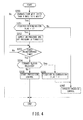
Fig. 4] Fig. 4 is a flowchart for explaining engaging control of this embodiment. - An embodiment of the present invention will be described below by referring to the attached drawings.
-
Fig. 1 illustrates a schematic configuration of a vehicle provided with an automatic transmission according to the embodiment of the present invention. The vehicle includes anengine 1, atorque converter 2, and atransmission 3, and output rotation of theengine 1 is transmitted to a driving wheel, not shown, through thetorque converter 2, thetransmission 3, and a differential gear unit, not shown. - The
transmission 3 is a stepped or non-stage automatic transmission. Thetransmission 3 includes areverse brake 4 and aforward clutch 5. Thetransmission 3 reverses rotation of theengine 1 and outputs it in a state in which thereverse brake 4 is engaged, while the rotation of theengine 1 is outputted while a rotation direction is maintained in a state in which theforward clutch 5 is engaged. - The
reverse brake 4 is a prior-art friction element which is engaged by supplying an engaging pressure, and the engaging pressure needs to be continuously supplied in order to maintain the engaged state. It is only necessary to stop supply of the engaging pressure to release thereverse brake 4. - The
forward clutch 5 is a friction element provided with a lock mechanism BL as will be described later. If an ON pressure is supplied to theforward clutch 5 and the lock mechanism BL enters a lock state, theforward clutch 5 can maintain the engaged state even if the supply of the ON pressure is stopped. In order to release theforward clutch 5, it is only necessary to supply an OFF pressure to theforward clutch 5 so as to bring the lock mechanism BL into a release state, and once the lock mechanism BL enters the release state, theforward clutch 5 can maintain the release state even if the supply of the OFF pressure is stopped. A configuration of theforward clutch 5 will be described later in detail. - If the
reverse brake 4 and theforward clutch 5 are both engaged at the same time, an interlock state in which an input/output shaft of thetransmission 3 cannot rotate is brought about and thus, engaging of them is performed selectively. - The
hydraulic control circuit 7 includes a regulator valve for regulating a hydraulic pressure from ahydraulic pump 8 driven by theengine 1 to a line pressure, a solenoid valve for regulating a hydraulic pressure to be supplied to the friction element (if thetransmission 3 is a continuously variable transmission, a constituent element of the continuously variable transmission mechanism in addition) including theforward clutch 5 with a line pressure as a source pressure, and an oil path connecting thehydraulic pump 8, each valve and each friction element. - Each valve of the
hydraulic control circuit 7 is controlled on the basis of a control signal from atransmission controller 9. Thetransmission controller 9 is constituted by a CPU, a ROM, a RAM, an input/output interface and the like, determines a running state of the vehicle on the basis of various signals inputted from various sensors and an engine controller and outputs an instruction to thehydraulic control circuit 7 so that a gear position (a speed ratio if thetransmission 3 is the continuously variable transmission) suitable for the running state is realized. - To the
transmission controller 9, signals and the like from arotation speed sensor 101 for detecting a rotation speed Ne of theengine 1, arotation speed sensor 102 for detecting an input rotation speed of thetransmission 3, arotation speed sensor 103 for detecting an output rotation speed of thetransmission 3, amode detection switch 104 for detecting a mode of thetransmission 3 selected by aselect switch 11, an accelerator opening-degree sensor 105 for detecting an operation amount of an accelerator pedal (hereinafter referred to as an "accelerator opening-degree APO"), abrake switch 106 for detecting ON/OFF of the brake, aG sensor 107 for detecting acceleration/ deceleration of the vehicle and the like are inputted. - The
select switch 11 is a lever type or a button type and is capable of selecting any one of modes, that is, a parking mode (hereinafter referred to as a "P mode"), a reverse mode (hereinafter referred to as an "R mode"), a neutral mode (hereinafter referred to as an "N mode"), and a drive mode (hereinafter referred to as a "D mode") as the mode of thetransmission 3 by operating the lever or the button. - The
transmission controller 9 engages or releases thereverse brake 4 and theforward clutch 5, respectively, in response to the mode selected by theselect switch 11. Specifically, in the D mode, thereverse brake 4 is released, and theforward clutch 5 is engaged. In the R mode, thereverse brake 4 is engaged, and theforward clutch 5 is released. In the P mode and the N mode, thereverse brake 4 and theforward clutch 5 are released. - Subsequently, a detailed configuration of the
forward clutch 5 will be described. -
Fig. 2 illustrates sections of theforward clutch 5 and a clutch operation pack 6 for operating this. Each configuration will be described below. - The
forward clutch 5 includes aclutch drum 51, aclutch hub 52, a drivenplate 53, adrive plate 54, and aretainer plate 55. - The
clutch drum 51 and theclutch hub 52 are arranged coaxially. To theclutch drum 51, a rotating element (shaft, gear and the like), not shown, is coupled. To theclutch hub 52, another rotating element (shaft, gear and the like), not shown, is coupled. - On the
clutch drum 51, the drivenplate 53 is mounted by spline coupling slidably in the axial direction. On theclutch hub 52, thedrive plate 54 is mounted by spline coupling slidably in the axial direction. Four pieces of the drivenplates 53 and four pieces of thedrive plates 54 are arranged alternately, and clutch facing is bonded on friction surfaces on both sides of thedrive plates 54. - The
clutch drum 51 transmits rotation inputted from the rotating element coupled to theclutch drum 51 to theclutch hub 52 through the drivenplate 53 and thedrive plate 54. - The
retainer plate 55 is interposed between thedrive plate 54 arranged on an end portion on a side opposite to thehydraulic piston 61 and asnap ring 64 fixed to a groove in an inner periphery of theclutch drum 51. One of surfaces of theretainer plate 55 is the friction surface. Theretainer plate 55 has a thickness in the axial direction larger than that of the drivenplate 53 and prevents falling-down of the drivenplate 53 and thedrive plate 54. - The clutch operation pack 6 includes the
hydraulic piston 61, an ONpressure piston chamber 62, an OFFpressure piston chamber 63, asnap ring 64, adiaphragm spring 65, apartition plate 66, and the lock mechanism BL. - The
hydraulic piston 61 is arranged capable of displacement in the axial direction with respect to theforward clutch 5. One of the surfaces of thehydraulic piston 61 is an ONpressure receiving surface 61a, and the other surface is an OFFpressure receiving surface 61b. - The ON
pressure piston chamber 62 is defined between theclutch drum 51 and thehydraulic piston 61 in order to have an ON pressure act on the ONpressure receiving surface 61a of thehydraulic piston 61. - The OFF
pressure piston chamber 63 is defined between thepartition plate 66 fixed to theclutch drum 51 and thehydraulic piston 61 in order to have an OFF pressure act on the OFFpressure receiving surface 61b of thehydraulic piston 61. - The
snap ring 64 is arranged at a position on a side opposite to thehydraulic piston 61 sandwiching theforward clutch 5 between them and supports theforward clutch 5 in the axial direction. - The
diaphragm spring 65 is interposed between a clutch-side end surface 61 c of thehydraulic piston 61 and a piston-side end surface 5a of theforward clutch 5. Two pieces of the diaphragm springs 65 are arranged by being stacked in the axial direction, and when thehydraulic piston 61 is moved in an engaging direction toward thesnap ring 64, an engaging force is made to act on theforward clutch 5. - The lock mechanism BL is built in the
clutch drum 51 and is constituted by thehydraulic piston 61, aball holding piston 67, and aball 68. - The
hydraulic piston 61 is arranged capable of displacement in the axial direction with respect to theforward clutch 5. On thehydraulic piston 61, anaccommodating portion 61 d and ataper surface 61 e are provided. Theaccommodating portion 61d accommodates theball 68 when movement of thehydraulic piston 61 in a release direction is regulated. Thetaper surface 61e is formed continuously to theaccommodating portion 61 d and it pushes theball 68 into the inside when thehydraulic piston 61 makes a stroke in the release direction. - The
ball holding piston 67 is arranged in a cylindrical space defined by an inner-peripheralcylindrical portion 51a of theclutch drum 51 covering thehydraulic piston 61 and a partitioncylindrical wall portion 51 b protruding in the axial direction from theclutch drum 51. Theball holding piston 67 moves in the axial direction when the ON pressure or the OFF pressure acts. A space between an outer peripheral surface of theball holding piston 67 and the partitioncylindrical wall portion 51b is sealed by aseal ring 84, a space between an inner peripheral surface of theball holding piston 67 and the inner-peripheralcylindrical portion 51a is sealed by aseal ring 85, and a space between an inner peripheral surface of thehydraulic piston 61 and the partitioncylindrical wall portion 51b is sealed by aseal ring 86. As a result, the ONpressure piston chamber 62 and the OFFpressure piston chamber 63 are defined on both sides of thehydraulic piston 61. - An ON
pressure port 51d opened in theclutch drum 51 and the ONpressure piston chamber 62 communicate with each other through an ONpressure communication groove 67a formed in theball holding piston 67 and an ONpressure communication hole 51e opened in the partitioncylindrical wall portion 51b. An OFFpressure port 51f opened in theclutch drum 51 and the OFFpressure piston chamber 63 communicate with each other through an OFFpressure communication groove 67b formed in theball holding piston 67 and an OFF pressure communication gap ensured between an end portion of the partitioncylindrical wall portion 51b and thepartition plate 66. - On the
ball holding piston 67, anaccommodating portion 67c, atapered surface 67d, and alock surface 67e are provided. Theaccommodating portion 67c accommodates theball 68 when movement of thehydraulic piston 61 in the release direction is allowed. Thetaper surface 67d and thelock surface 67e are formed continuously to theaccommodating portion 67c, and when theball holding piston 67 makes a stroke toward theforward clutch 5, thetaper surface 67d pushes out theball 68 to an outside, and thelock surface 67e locks the pushed-outball 68 at that position. - The
ball 68 is provided on aball hole 51c opened in the partitioncylindrical wall portion 51b. Theball 68 receives a force from the taper surfaces 61e and 67d of thepistons hydraulic piston 61 and theball holding piston 67 by means of an action of the ON pressure or the OFF pressure and moves in a radial direction between a lock position and an unlock position. - According to the above-described configuration, by supplying the ON pressure to the ON
pressure piston chamber 62, thehydraulic piston 61 moves to the engaging direction approaching theforward clutch 5, and theforward clutch 5 enters a engaged state by an urging force of thediaphragm spring 65 which is pushed/compressed. When thehydraulic piston 61 moves in the engaging direction, theball 68 moves in an outer diameter direction by a centrifugal force by rotation and the hydraulic pressure, and theball 68 is accommodated in theaccommodating portion 61d. Then, with an ON pressure action onto theball holding piston 67, theball holding piston 67 moves in the axial direction (direction toward the forward clutch 5), and theball 68 held by theaccommodating portion 67c is held by thelock surface 67e. - As a result, the lock mechanism BL enters a lock state, and movement of the
hydraulic piston 61 in the release direction is regulated, and even if the ON pressure is drained, the engaged state of theforward clutch 5 is maintained. The ON pressure to the ONpressure piston chamber 62 is supplied only during the engaging operation, and supply of the ON pressure in order to maintain the engaged state of theforward clutch 5 is not necessary. - A lower limit value of the ON pressure which can bring the lock mechanism BL into the lock state is called a lock pressure and is determined on the basis of a spring constant of the
diaphragm spring 65, an area of the ONpressure receiving surface 61a of thehydraulic piston 61 and the like. - Moreover, the
forward clutch 5 can also enter the engaged state without bringing the lock mechanism BL into the lock state by limiting a hydraulic pressure to be supplied to thehydraulic piston 61 to a hydraulic pressure lower than the ON pressure (hydraulic pressure lower than the lock pressure). In this case, since the movement of thehydraulic piston 61 in the release direction cannot be regulated by the lock mechanism BL, the limited hydraulic pressure needs to be continuously supplied to thehydraulic piston 61 in order to maintain the engaged state of theforward clutch 5. - Control of the
transmission controller 9 by which the lock mechanism BL enters the lock state by supply/discharge of the ON pressure so as to maintain the engaged state of theforward clutch 5 is called normal engaging control. On the other hand, control of thetransmission controller 9 by which a limited hydraulic pressure lower than the above-described ON pressure is continuously supplied, and theforward clutch 5 is maintained in the engaged state without bringing the lock mechanism BL into the lock state is called garage shift engaging control. When a D mode is selected by theselect switch 11, thetransmission controller 9 selects the normal engaging control or the garage shift engaging control on the basis of whether or not the operation of theselect switch 11 is garage shift and executes the selected control. - Moreover, when the OFF pressure is supplied to the OFF
pressure piston chamber 63, theball holding piston 67 moves in the axial direction (direction away from the forward clutch 5) from a holding position of theball 68 by thelock surface 67e to a holding release position. A force combining a force by the OFF pressure and a reaction force of the engaging force by thediaphragm spring 65 acts on thehydraulic piston 61, and thehydraulic piston 61 makes a stroke in a return direction and pushes back theball 68 in an unlock direction. When theball 68 moves to the unlock position, the lock mechanism BL enters an unlock state. - When the
forward clutch 5 is released, the ON pressure is in a state of zero and thus, even if the OFF pressure is drained, the state in which theball 68 is accommodated in theaccommodating portion 67c of theball holding piston 67 is maintained. The OFF pressure to the OFFpressure piston chamber 63 is supplied only during a release operation, and supply of the OFF pressure in order to maintain the unlock state of theforward clutch 5 is not necessary. - Control of the
transmission controller 9 for realizing supply/discharge of the OFF pressure is called release control, and thetransmission controller 9 executes the release control when a mode other than the D mode is selected by theselect switch 11. - The ON pressure to the
forward clutch 5 is not supplied when a non-running mode such as the N mode, the P mode or the like is selected due to the configuration of the hydraulic circuit and is supplied only when the D-mode running mode is selected. - Subsequently, the release control of this embodiment will be described by using a flowchart in
Fig. 3 . - At Step S100, the
transmission controller 9 determines whether or not theselect switch 11 has been changed from the D mode to a mode other than the D mode on the basis of a signal of themode detection switch 104. When the D mode has been changed to a mode other than the D mode, processing proceeds to Step S101, while the mode has not been changed from the D mode to a mode other than D mode, the processing is finished. - At Step S101, the
transmission controller 9 supplies the OFF pressure to the OFFpressure piston chamber 63 and starts the release control. - At Step S102, the
transmission controller 9 measures time since the OFF pressure was supplied to the OFFpressure piston chamber 63, compares the measured time with a first predetermined time and determines whether or not the measured time has reached the first predetermined time. If the measured time has reached the first predetermined time, the processing proceeds to Step S103. The first predetermined time is time set in advance and time required for the lock mechanism BL to be changed from the lock state to the unlock state so as to release theforward clutch 5. - At Step S103, the
transmission controller 9 stops supply of the OFF pressure to the OFFpressure piston chamber 63 and drains the OFF pressure. - At Step S104, the
transmission controller 9 determines whether or not theforward clutch 5 has been released. Specifically, thetransmission controller 9 determines whether or not theforward clutch 5 has been released on the basis of the signals from therotation speed sensor 101 for detecting a rotation speed Ne of theengine 1 and therotation speed sensor 102 for detecting an input rotation speed of thetransmission 3. If the OFF pressure is supplied to the OFFpressure piston chamber 63 and the lock mechanism BL is released, a differential rotation generated in the respective rotation speeds becomes small. That is because, even if theselect switch 11 is changed from the D mode to the mode other than the D mode and theforward clutch 5 is released, the rotation speed of theengine 1 scarcely changes, but regarding the input rotation speed of thetransmission 3, release of theforward clutch 5 reduces a rotation speed lowering amount for inertia of thetransmission 3. Thetransmission controller 9 determines that theforward clutch 5 has been released when the respective rotation speeds have fallen to the predetermined differential rotation or less since the OFF pressure was supplied to the OFFpressure piston chamber 63. If theforward clutch 5 is released, thetransmission controller 9 finishes the release control, and the processing is finished. If theforward clutch 5 has not been released, there is a concern that thehydraulic piston 61 is fixed, and thus, the processing proceeds to Step S105. The fixation of thehydraulic piston 61 occurs when the lock mechanism BL cannot be released such that a part of theball 68 is broken and a part of the broken portion is caught between thehydraulic piston 61 and the partitioncylindrical wall portion 51b or that thehydraulic piston 61 is inclined and brought into contact with theclutch drum 51 and prevents movement of thehydraulic piston 61 and the like, for example. - At Step S105, the
transmission controller 9 supplies the OFF pressure to the OFFpressure piston chamber 63 in order to solve the fixation of thehydraulic piston 61. Here, the OFF pressure supplied at Step S101 or the OFF pressure higher than the OFF pressure supplied at Step S101 is supplied as the OFF pressure. By supplying the OFF pressure to the OFFpressure piston chamber 63 again, fixation of thehydraulic piston 61 can be solved by an impact and pressing in the supply of the OFF pressure. - At Step S106, the
transmission controller 9 measures the time since the OFF pressure was supplied to the OFFpressure piston chamber 63 again and compares the measured time with a second predetermined time. If the measured time has reached the second predetermined time, the processing proceeds to Step S107. The second predetermined time is time set in advance and time required for solving the fixation of thehydraulic piston 61 and for releasing theforward clutch 5. - At Step S107, the
transmission controller 9 stops the supply of the OFF pressure to the OFFpressure piston chamber 63 and drains the OFF pressure. - At Step S108, the
transmission controller 9 determines again whether or not theforward clutch 5 has been released. Specifically, thetransmission controller 9 determines whether or not the fixation of thehydraulic piston 61 has been solved and theforward clutch 5 has been released on the basis of the signals from therotation speed sensor 101 and therotation speed sensor 102. The specific determining method is the same as Step S104. If theforward clutch 5 has been released, thetransmission controller 9 finishes the release control, and the processing is finished. If theforward clutch 5 has not been released, the processing proceeds to Step S109. - At Step S109, the
transmission controller 9 determines that thehydraulic piston 61 is fixed, sets a fixation determination flag to "1" and finishes the release control, and the processing is finished. The fixation determination flag is "0" in an initial state. - Subsequently, engaging control of this embodiment will be described by using a flowchart in
Fig. 4 . The normal engaging control will be described here, but it may be the garage shift engaging control. - At Step S200, the
transmission controller 9 determines whether or not theselect switch 11 has been changed from the mode other than the D mode to the D mode on the basis of the signal of themode detection switch 104. If the mode other than the D mode has been changed to the D mode, the processing proceeds to Step S201, while in the other cases, the processing is finished. - At Step S201, the
transmission controller 9 determines whether or not the fixation determination flag is "1" or not. If the fixation determination flag is "1", the processing proceeds to Step S202, while if the fixation determination flag is "0", the processing proceeds to Step S207. - At Step S202, the
transmission controller 9 alternately repeats the supply of the ON pressure which can be supplied when the D mode is selected to the ONpressure piston chamber 62 and the supply of the OFF pressure to the OFFpressure piston chamber 63 in order to solve the fixation of thehydraulic piston 61. By performing supply of the ON pressure and the OFF pressure alternately, the fixation of thehydraulic piston 61 can be solved by the impact and pressing in supply/discharge of the hydraulic pressure. The ON pressure and the OFF pressure supplied here are the hydraulic pressures set in advance. Such supply of the hydraulic pressure is continued until a third predetermined time which will be described at Step S203 has elapsed. - At Step S203, the
transmission controller 9 measures time since the supply of the ON pressure and the OFF pressure was started alternately and compares the measured time with the third predetermined time. When the measured time has reached the third predetermined time, thetransmission controller 9 finishes alternate supply of the ON pressure and the OFF pressure. After that, the processing proceeds to Step S204. The third predetermined time is short time set in advance and time not affecting starting performance of the vehicle. - At Step S204, the
transmission controller 9 determines again whether or not theforward clutch 5 has been released. Specifically, thetransmission controller 9 determines whether or not theforward clutch 5 has been released on the basis of the signals from therotation sensor 101 for detecting the rotation speed Ne of theengine 1 and therotation speed sensor 102 for detecting the input rotation speed of thetransmission 3. If a situation in which the respective rotation speeds fall to a predetermined differential rotation or less has occurred since the ON pressure and the OFF pressure were supplied alternately, thetransmission controller 9 determines that theforward clutch 5 has been released. If theforward clutch 5 has been released, the processing proceeds to Step S206, while if theforward clutch 5 has not been released, the processing proceeds to Step S205. - At Step S205, the
transmission controller 9 starts protection control. In the protection control, an alarm lamp is lighted, and a torque of theengine 1 is lowered, for example. - At Step S206, the
transmission controller 9 changes the fixation determination flag to "0". The fixation determination flag is "0" unless it is changed to "1" at Step S109. - At Step S207, the
transmission controller 9 executes the engaging control by supplying the ON pressure to the ONpressure piston chamber 62 and engages theforward clutch 5. - An effect of this embodiment will be described.
- Even if the
select switch 11 is changed from the D mode to the mode other than the D mode and the OFF pressure is supplied to the OFFpressure piston chamber 63, when theforward clutch 5 is not released, by supplying the OFF pressure to the OFFpressure piston chamber 63 again, the fixation of thehydraulic piston 61 can be solved, and theforward clutch 5 can be released. - Even if the
select switch 11 is changed from the D mode to the mode other than the D mode and the OFF pressure is supplied again to the OFFpressure piston chamber 63 but still the fixation of thehydraulic piston 61 is not solved, when theselect switch 11 is changed from the mode other than the D mode to the D mode, the ON pressure supply capable of supply to the ONpressure piston chamber 62 when the D mode is selected and the OFF pressure supply to the OFFpressure piston chamber 63 is performed alternately. As a result, the fixation of thehydraulic piston 61 can be solved. - The embodiment of the present invention has been described above, but the above-described embodiment illustrates only a part of the application example of the present invention and is not intended to limit the technical range of the present invention to the specific configuration of the above-described embodiment.
- In the above-described embodiment, the signals from the
rotation speed sensors forward clutch 5 has been released, but this is not limiting, and if a torque sensor is provided, for example, whether or not theforward clutch 5 has been released may be determined on the basis of a signal from the torque sensor. - In the above-described embodiment, in the case of the mode other than the D mode, that is, the N mode and the P mode, for example, the supply of the ON pressure to the
forward clutch 5 is prohibited, while in the case of the D mode, the ON pressure and the OFF pressure are made capable of being supplied, but the ON pressure may be also made capable of being supplied in the mode other than the D mode. In this case, the ON pressure and the OFF pressure may be supplied alternately at Step S105, or the ON pressure and the OFF pressure may be supplied alternately before Step S109. The fixation of thehydraulic piston 61 may be solved in this way. - The present application claims for priority based on Japanese Patent Application No.
2012-212561
Claims (3)
- An automatic transmission arranged in a power transmission path and having a friction element in which, when an ON pressure is supplied to a engaging-side oil chamber, a hydraulic piston is moved and engaged and a lock mechanism enters a lock state, when the lock mechanism enters the lock state, a engaged state is maintained even if a hydraulic pressure of the engaging-side oil chamber is lowered, and when an OFF pressure is supplied to a release-side oil chamber when the lock mechanism is in the lock state, the lock mechanism enters an unlock state, the hydraulic piston is moved and released, and a release state is maintained even if the hydraulic pressure of the release-side oil chamber is lowered, comprising:a hydraulic control unit configured to be controllable the ON pressure and the OFF pressure;a mode selection unit configured to be selectable a mode for engaging the friction element or a mode for releasing the friction element as a mode of the automatic transmission; anda release-state detection unit configured to detect whether or not the friction element has been released when the mode for releasing the friction element is selected from the mode for engaging the friction element and the OFF pressure is supplied to the release-side oil chamber, whereinthe hydraulic control unit is configured to supply the OFF pressure to the release-side oil chamber again if the friction element is not released even if the OFF pressure is supplied to the release-side oil chamber.
- The automatic transmission according to claim 1, wherein
when the friction element is not released even if the OFF pressure is supplied again to the release-side oil chamber, the hydraulic control unit supplies the ON pressure and the OFF pressure alternately when the mode of the automatic transmission is changed from the mode for releasing the friction element to the mode for engaging the friction element. - A control method of an automatic transmission for controlling the automatic transmission arranged in a power transmission path and having a friction element in which, when an ON pressure is supplied to a engaging-side oil chamber, the hydraulic piston is moved and engaged and a lock mechanism enters a lock state, when the lock mechanism enters the lock state, a engaged state is maintained even if a hydraulic pressure of the engaging-side oil chamber is lowered, and when an OFF pressure is supplied to a release-side oil chamber when the lock mechanism is in the lock state, the lock mechanism enters an unlock state, the hydraulic piston is moved and released, and a release state is maintained even if the hydraulic pressure of the release-side oil chamber is lowered, comprising:detecting whether a mode of the automatic transmission is a mode for engaging the friction element or a mode for releasing the friction element;detecting whether or not the friction element has been released when the mode of the automatic transmission is changed from the mode for engaging the friction element to the mode for releasing the friction element and the OFF pressure is supplied to the release-side oil chamber; andsupplying the OFF pressure again to the release-side oil chamber when the mode of the automatic transmission is changed from the mode for engaging the friction element to the mode for releasing the friction element and the friction element is not released even if the OFF pressure is supplied to the release-side oil chamber.
Applications Claiming Priority (2)
| Application Number | Priority Date | Filing Date | Title |
|---|---|---|---|
| JP2012212561 | 2012-09-26 | ||
| PCT/JP2013/075435 WO2014050725A1 (en) | 2012-09-26 | 2013-09-20 | Automatic transmission and automatic-transmission control method |
Publications (1)
| Publication Number | Publication Date |
|---|---|
| EP2902652A1 true EP2902652A1 (en) | 2015-08-05 |
Family
ID=50388129
Family Applications (1)
| Application Number | Title | Priority Date | Filing Date |
|---|---|---|---|
| EP13842398.3A Withdrawn EP2902652A1 (en) | 2012-09-26 | 2013-09-20 | Automatic transmission and automatic-transmission control method |
Country Status (6)
| Country | Link |
|---|---|
| US (1) | US20150247570A1 (en) |
| EP (1) | EP2902652A1 (en) |
| JP (1) | JP5844913B2 (en) |
| KR (1) | KR20150048169A (en) |
| CN (1) | CN104685255A (en) |
| WO (1) | WO2014050725A1 (en) |
Families Citing this family (3)
| Publication number | Priority date | Publication date | Assignee | Title |
|---|---|---|---|---|
| JP5844912B2 (en) * | 2012-09-26 | 2016-01-20 | ジヤトコ株式会社 | Automatic transmission having friction element with lock mechanism and control method thereof |
| WO2015192861A1 (en) * | 2014-06-17 | 2015-12-23 | Volvo Truck Corporation | Improved clutch control |
| JP6394627B2 (en) * | 2016-03-09 | 2018-09-26 | トヨタ自動車株式会社 | Lubrication device for engagement mechanism |
Family Cites Families (13)
| Publication number | Priority date | Publication date | Assignee | Title |
|---|---|---|---|---|
| DE2540191C3 (en) * | 1975-09-10 | 1981-08-13 | Zahnradfabrik Friedrichshafen Ag, 7990 Friedrichshafen | Pressure fluid operated multi-plate clutch with upright ring cylinder |
| JPS5939326U (en) * | 1982-09-07 | 1984-03-13 | 三菱農機株式会社 | Hydraulic multi-disc clutch device |
| CA1217834A (en) * | 1983-06-30 | 1987-02-10 | Toshihiro Hattori | Method of controlling gear changing operation in automatic transmission |
| JPS6111028U (en) * | 1984-06-25 | 1986-01-22 | 日産自動車株式会社 | clutch device |
| JP2689630B2 (en) * | 1989-08-09 | 1997-12-10 | トヨタ自動車株式会社 | Hydraulic control device for vehicle hydraulic clutch |
| JPH0712221A (en) | 1993-06-29 | 1995-01-17 | Matsuda Sangyo Kk | Fastening force adjusting device for automatic transmission |
| JP2005257049A (en) * | 2004-03-15 | 2005-09-22 | Suzuki Motor Corp | Hydraulic friction engagement device |
| DE102008027070A1 (en) * | 2007-06-20 | 2008-12-24 | Luk Lamellen Und Kupplungsbau Beteiligungs Kg | Locking mechanism for clutches and brakes |
| US8172058B2 (en) * | 2009-01-12 | 2012-05-08 | GM Global Technology Operations LLC | Latching clutch assembly and method of operating the same |
| JP2010216501A (en) * | 2009-03-13 | 2010-09-30 | Toyota Motor Corp | Piston structure for automatic transmission |
| JP2010242852A (en) * | 2009-04-06 | 2010-10-28 | Honda Motor Co Ltd | Friction engagement device |
| JP5461262B2 (en) * | 2010-03-23 | 2014-04-02 | 富士重工業株式会社 | Hydraulic control valve control device |
| JP5669641B2 (en) * | 2011-03-22 | 2015-02-12 | ジヤトコ株式会社 | Multi-plate friction engagement mechanism |
-
2013
- 2013-09-20 EP EP13842398.3A patent/EP2902652A1/en not_active Withdrawn
- 2013-09-20 US US14/430,858 patent/US20150247570A1/en not_active Abandoned
- 2013-09-20 KR KR1020157007139A patent/KR20150048169A/en not_active Ceased
- 2013-09-20 WO PCT/JP2013/075435 patent/WO2014050725A1/en not_active Ceased
- 2013-09-20 JP JP2014538455A patent/JP5844913B2/en not_active Expired - Fee Related
- 2013-09-20 CN CN201380049920.6A patent/CN104685255A/en active Pending
Non-Patent Citations (1)
| Title |
|---|
| See references of WO2014050725A1 * |
Also Published As
| Publication number | Publication date |
|---|---|
| JP5844913B2 (en) | 2016-01-20 |
| JPWO2014050725A1 (en) | 2016-08-22 |
| WO2014050725A1 (en) | 2014-04-03 |
| CN104685255A (en) | 2015-06-03 |
| KR20150048169A (en) | 2015-05-06 |
| US20150247570A1 (en) | 2015-09-03 |
Similar Documents
| Publication | Publication Date | Title |
|---|---|---|
| JP5844916B2 (en) | Automatic transmission and control method thereof | |
| US20150247570A1 (en) | Automatic transmission and controlling method of automatic transmission | |
| JP5844912B2 (en) | Automatic transmission having friction element with lock mechanism and control method thereof | |
| JP5844915B2 (en) | Automatic transmission and control method thereof | |
| JP5830173B2 (en) | Automatic transmission having friction element with lock mechanism and control method thereof | |
| JP5844914B2 (en) | Automatic transmission and control method thereof | |
| JP5844911B2 (en) | Automatic transmission having friction element with lock mechanism and control method thereof | |
| EP2902667A1 (en) | Automatic transmission equipped with friction element having locking mechanism attached thereto, and control method therefor | |
| EP2908032A1 (en) | Automatic transmission equipped with friction element having locking mechanism attached thereto, and control method therefor |
Legal Events
| Date | Code | Title | Description |
|---|---|---|---|
| PUAI | Public reference made under article 153(3) epc to a published international application that has entered the european phase |
Free format text: ORIGINAL CODE: 0009012 |
|
| 17P | Request for examination filed |
Effective date: 20150323 |
|
| AK | Designated contracting states |
Kind code of ref document: A1 Designated state(s): AL AT BE BG CH CY CZ DE DK EE ES FI FR GB GR HR HU IE IS IT LI LT LU LV MC MK MT NL NO PL PT RO RS SE SI SK SM TR |
|
| AX | Request for extension of the european patent |
Extension state: BA ME |
|
| DAX | Request for extension of the european patent (deleted) | ||
| STAA | Information on the status of an ep patent application or granted ep patent |
Free format text: STATUS: THE APPLICATION HAS BEEN WITHDRAWN |
|
| 18W | Application withdrawn |
Effective date: 20160704 |