EP2902608A1 - Aft shrouded geared turbofan - Google Patents
Aft shrouded geared turbofan Download PDFInfo
- Publication number
- EP2902608A1 EP2902608A1 EP15152453.5A EP15152453A EP2902608A1 EP 2902608 A1 EP2902608 A1 EP 2902608A1 EP 15152453 A EP15152453 A EP 15152453A EP 2902608 A1 EP2902608 A1 EP 2902608A1
- Authority
- EP
- European Patent Office
- Prior art keywords
- gas turbine
- set forth
- turbine engine
- fan
- engine
- Prior art date
- Legal status (The legal status is an assumption and is not a legal conclusion. Google has not performed a legal analysis and makes no representation as to the accuracy of the status listed.)
- Granted
Links
Images

Classifications
-
- F—MECHANICAL ENGINEERING; LIGHTING; HEATING; WEAPONS; BLASTING
- F02—COMBUSTION ENGINES; HOT-GAS OR COMBUSTION-PRODUCT ENGINE PLANTS
- F02K—JET-PROPULSION PLANTS
- F02K1/00—Plants characterised by the form or arrangement of the jet pipe or nozzle; Jet pipes or nozzles peculiar thereto
- F02K1/54—Nozzles having means for reversing jet thrust
- F02K1/64—Reversing fan flow
- F02K1/66—Reversing fan flow using reversing fan blades
-
- F—MECHANICAL ENGINEERING; LIGHTING; HEATING; WEAPONS; BLASTING
- F02—COMBUSTION ENGINES; HOT-GAS OR COMBUSTION-PRODUCT ENGINE PLANTS
- F02C—GAS-TURBINE PLANTS; AIR INTAKES FOR JET-PROPULSION PLANTS; CONTROLLING FUEL SUPPLY IN AIR-BREATHING JET-PROPULSION PLANTS
- F02C7/00—Features, components parts, details or accessories, not provided for in, or of interest apart form groups F02C1/00 - F02C6/00; Air intakes for jet-propulsion plants
- F02C7/36—Power transmission arrangements between the different shafts of the gas turbine plant, or between the gas-turbine plant and the power user
-
- F—MECHANICAL ENGINEERING; LIGHTING; HEATING; WEAPONS; BLASTING
- F02—COMBUSTION ENGINES; HOT-GAS OR COMBUSTION-PRODUCT ENGINE PLANTS
- F02K—JET-PROPULSION PLANTS
- F02K3/00—Plants including a gas turbine driving a compressor or a ducted fan
- F02K3/02—Plants including a gas turbine driving a compressor or a ducted fan in which part of the working fluid by-passes the turbine and combustion chamber
- F02K3/04—Plants including a gas turbine driving a compressor or a ducted fan in which part of the working fluid by-passes the turbine and combustion chamber the plant including ducted fans, i.e. fans with high volume, low pressure outputs, for augmenting the jet thrust, e.g. of double-flow type
- F02K3/062—Plants including a gas turbine driving a compressor or a ducted fan in which part of the working fluid by-passes the turbine and combustion chamber the plant including ducted fans, i.e. fans with high volume, low pressure outputs, for augmenting the jet thrust, e.g. of double-flow type with aft fan
-
- F—MECHANICAL ENGINEERING; LIGHTING; HEATING; WEAPONS; BLASTING
- F02—COMBUSTION ENGINES; HOT-GAS OR COMBUSTION-PRODUCT ENGINE PLANTS
- F02K—JET-PROPULSION PLANTS
- F02K3/00—Plants including a gas turbine driving a compressor or a ducted fan
- F02K3/02—Plants including a gas turbine driving a compressor or a ducted fan in which part of the working fluid by-passes the turbine and combustion chamber
- F02K3/04—Plants including a gas turbine driving a compressor or a ducted fan in which part of the working fluid by-passes the turbine and combustion chamber the plant including ducted fans, i.e. fans with high volume, low pressure outputs, for augmenting the jet thrust, e.g. of double-flow type
- F02K3/072—Plants including a gas turbine driving a compressor or a ducted fan in which part of the working fluid by-passes the turbine and combustion chamber the plant including ducted fans, i.e. fans with high volume, low pressure outputs, for augmenting the jet thrust, e.g. of double-flow type with counter-rotating, e.g. fan rotors
-
- F—MECHANICAL ENGINEERING; LIGHTING; HEATING; WEAPONS; BLASTING
- F05—INDEXING SCHEMES RELATING TO ENGINES OR PUMPS IN VARIOUS SUBCLASSES OF CLASSES F01-F04
- F05D—INDEXING SCHEME FOR ASPECTS RELATING TO NON-POSITIVE-DISPLACEMENT MACHINES OR ENGINES, GAS-TURBINES OR JET-PROPULSION PLANTS
- F05D2260/00—Function
- F05D2260/40—Transmission of power
- F05D2260/403—Transmission of power through the shape of the drive components
- F05D2260/4031—Transmission of power through the shape of the drive components as in toothed gearing
Definitions
- This application relates to a gas turbine engine, wherein the fan for providing bypass air is mounted aft of a core engine.
- Gas turbine engines are known and, typically, include a fan at a forward end of the engine delivering air into a bypass duct as propulsion air and also into a core engine.
- the air in the core engine is compressed in a compressor and delivered into a combustion section where it is mixed with fuel and ignited. Products of this combustion pass downstream over turbine rotors which, in turn, drive compressor rotors and a fan rotor to rotate.
- a turbine rotor has rotated at a single speed with the fan rotor. This has been a limitation on the speed of the turbine rotor as the fan rotor cannot rotate at unduly high speeds. More recently, it has been proposed to include a gear reduction between a fan drive turbine and the fan rotor. This allows the fan rotor to rotate at slower speeds and allows the fan drive turbine rotor to rotate at higher speeds.
- propellers driven by a turbine rotor in a gas turbine engine have generally not been provided with a shroud and, thus, do not provide bypass air as in a typical geared turbofan engine as described above.
- a gas turbine engine comprises an outer shroud.
- An inner core housing is positioned radially inwardly of the outer shroud, and has a core engine including at least one compressor rotor and at least one turbine rotor.
- a combustor section is intermediate the at least one compressor rotor and the at least one turbine rotor.
- a fan turbine is positioned downstream of the at least one turbine rotor. The fan turbine drives a gear reduction to, in turn, drive at least one fan blade positioned radially inwardly of the outer shroud.
- the at least one fan blade is a pair of axially spaced fan rotors.
- the pair of fan rotors rotate in opposed directions.
- the core engine includes at least a pair of compressor rotors and at least a pair of turbine rotors.
- the fan turbine is a third turbine rotor.
- an inlet to the core engine extends axially beyond an upstream end of the outer shroud.
- a pitch change mechanism is associated with the at least one fan blade.
- the pitch change mechanism is operable to change a pitch angle of blades on the at least one fan blade during normal operational conditions.
- the pitch change mechanism is operable or is also operable to move the at least one fan blade to a thrust reverser position at which it is configured to resist passage of air across the at least one fan blade to provide a thrust reversing function when an associated aircraft is landing.
- the pitch change mechanism is operable to change an angle of the at least one blade by more than 90° during movement to a or the thrust reverser position.
- the pitch change mechanism causes a shaft within a rotating housing to rotate to, in turn, change the pitch angle of the at least one blade.
- a thrust reverser is associated with the outer shroud and is used in combination with the pitch change mechanism.
- a thrust reverser is provided in the outer shroud and is configured to be driven radially outwardly to provide a thrust reverser function when an aircraft associated with the gas turbine engine is landing.
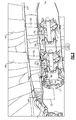
- Figure 1 shows a gas turbine engine 20 including an outer shroud 22.
- Bypass air is driven by a pair of fan rotors 46 and 48 within the shroud 22 and outwardly of the rotating housing 47.
- a core engine housing 24 is spaced inwardly of the shroud 22. Air passes into an inlet end 23 of the core housing 24 and then into a first compressor rotor 28.
- the first compressor rotor 28 is driven by a shaft 30 that is, in turn, driven by a low pressure turbine 32.
- Air from the first stage compressor 28 passes into a second stage compressor 34 which is driven by a shaft 36, in turn, driven by a turbine 38.
- the air from the higher stage compressor rotor 34 passes into a combustion section 40 where it is mixed with fuel and ignited. Products of this combustion pass downstream over the turbine rotors 38 and 32 driving them to rotate. Collectively, the elements 28, 30, 32, 34, 36, 38 and 40 could be called a core engine 26. Products of the combustion downstream of the turbine rotor 32 pass over a fan drive turbine 44.
- the turbine 44 is aft or downstream of the turbine rotor 32.
- the turbine 44 drives a gear reduction 42 which may be a planetary gear reduction and which, in turn, drives shafts 50 and 52 to rotate the housing 47 and propeller blades 46 and 48.
- An outer housing 45 defines a core exhaust nozzle 43 with rotating housing 47. Inlet 23 to the core engine extends axially beyond an upstream end 103 of outer shroud 22.
- a shell thrust reverser 100 is shown schematically which may pivot outwardly to provide a thrust reversal function when the engine 20 is mounted on an aircraft.
- the clamshell thrust reverser 100 is provided in outer shroud 22 and is driven radially outwardly to provide a thrust reverser function when an aircraft associated with the gas turbine engine is landing.
- the propellers 46 and 48 are provided with pitch change mechanisms 91 that not only allow a slight change in pitch for different operational conditions of the engine 20, but also may allow a dramatic change in the pitch angle for thrust reversal purposes.
- the pitch change mechanism may change the pitch angle by greater than 90° and on the order of 120° to provide a thrust reversing function.
- FIG. 2 shows details of the pitch change mechanism 91, including a shaft 54, a shaft 56 and the pitch change elements 58, which drive an angle of the shafts 54 and 56 to, in turn, change the angle of the blades 46 and 48.
- a control 101 is shown schematically and is operable in conjunction with operation of the engine to actuate the pitch change mechanism 91, not only during operational conditions, but further to drive the propeller blades 46 and 48 to a thrust reversing position when an associated aircraft is landing. That is, the pitch change mechanism 91 also is operable to move fan blades 46/48 to a position at which they will resist passage of air across the fan blades 46/48 to provide a thrust reversing function when an associated aircraft is landing.
- This thrust reversing function can be utilized in combination with the clamshell thrust reverser 100 as shown schematically in Figure 1 , or as an alternative.
- the propellers 44 and 46 are counter-rotating, meaning they rotate in opposed directions.
Landscapes
- Engineering & Computer Science (AREA)
- Chemical & Material Sciences (AREA)
- Combustion & Propulsion (AREA)
- Mechanical Engineering (AREA)
- General Engineering & Computer Science (AREA)
- Structures Of Non-Positive Displacement Pumps (AREA)
- Retarders (AREA)
Abstract
Description
- This application relates to a gas turbine engine, wherein the fan for providing bypass air is mounted aft of a core engine.
- Gas turbine engines are known and, typically, include a fan at a forward end of the engine delivering air into a bypass duct as propulsion air and also into a core engine. The air in the core engine is compressed in a compressor and delivered into a combustion section where it is mixed with fuel and ignited. Products of this combustion pass downstream over turbine rotors which, in turn, drive compressor rotors and a fan rotor to rotate.
- Traditionally, a turbine rotor has rotated at a single speed with the fan rotor. This has been a limitation on the speed of the turbine rotor as the fan rotor cannot rotate at unduly high speeds. More recently, it has been proposed to include a gear reduction between a fan drive turbine and the fan rotor. This allows the fan rotor to rotate at slower speeds and allows the fan drive turbine rotor to rotate at higher speeds.
- In addition, it has been proposed to include propellers driven by a turbine rotor in a gas turbine engine. These propellers have generally not been provided with a shroud and, thus, do not provide bypass air as in a typical geared turbofan engine as described above.
- In a featured embodiment, a gas turbine engine comprises an outer shroud. An inner core housing is positioned radially inwardly of the outer shroud, and has a core engine including at least one compressor rotor and at least one turbine rotor. A combustor section is intermediate the at least one compressor rotor and the at least one turbine rotor. A fan turbine is positioned downstream of the at least one turbine rotor. The fan turbine drives a gear reduction to, in turn, drive at least one fan blade positioned radially inwardly of the outer shroud.
- In an embodiment according to the previous embodiment, the at least one fan blade is a pair of axially spaced fan rotors.
- In another embodiment according to any of the previous embodiments, the pair of fan rotors rotate in opposed directions.
- In another embodiment according to any of the previous embodiments, the core engine includes at least a pair of compressor rotors and at least a pair of turbine rotors. The fan turbine is a third turbine rotor.
- In another embodiment according to any of the previous embodiments, an inlet to the core engine extends axially beyond an upstream end of the outer shroud.
- In another embodiment according to any of the previous embodiments, a pitch change mechanism is associated with the at least one fan blade.
- In another embodiment according to any of the previous embodiments, the pitch change mechanism is operable to change a pitch angle of blades on the at least one fan blade during normal operational conditions.
- In another embodiment according to any of the previous embodiments, the pitch change mechanism is operable or is also operable to move the at least one fan blade to a thrust reverser position at which it is configured to resist passage of air across the at least one fan blade to provide a thrust reversing function when an associated aircraft is landing.
- In another embodiment according to any of the previous embodiments, the pitch change mechanism is operable to change an angle of the at least one blade by more than 90° during movement to a or the thrust reverser position.
- In another embodiment according to any of the previous embodiments, the pitch change mechanism causes a shaft within a rotating housing to rotate to, in turn, change the pitch angle of the at least one blade.
- In another embodiment according to any of the previous embodiments, a thrust reverser is associated with the outer shroud and is used in combination with the pitch change mechanism.
- In another embodiment according to any of the previous embodiments, a thrust reverser is provided in the outer shroud and is configured to be driven radially outwardly to provide a thrust reverser function when an aircraft associated with the gas turbine engine is landing.
- These and other features may be best understood from the following drawings and specification.
-
-
Figure 1 schematically shows a gas turbine engine. -
Figure 2 shows a detail of the gas turbine engine. -
Figure 1 shows agas turbine engine 20 including anouter shroud 22. Bypass air is driven by a pair offan rotors shroud 22 and outwardly of the rotatinghousing 47. Acore engine housing 24 is spaced inwardly of theshroud 22. Air passes into aninlet end 23 of thecore housing 24 and then into afirst compressor rotor 28. Thefirst compressor rotor 28 is driven by ashaft 30 that is, in turn, driven by alow pressure turbine 32. Air from thefirst stage compressor 28 passes into asecond stage compressor 34 which is driven by ashaft 36, in turn, driven by aturbine 38. - The air from the higher
stage compressor rotor 34 passes into acombustion section 40 where it is mixed with fuel and ignited. Products of this combustion pass downstream over theturbine rotors elements core engine 26. Products of the combustion downstream of theturbine rotor 32 pass over afan drive turbine 44. Theturbine 44 is aft or downstream of theturbine rotor 32. Theturbine 44 drives agear reduction 42 which may be a planetary gear reduction and which, in turn, drivesshafts housing 47 andpropeller blades outer housing 45 defines acore exhaust nozzle 43 with rotatinghousing 47.Inlet 23 to the core engine extends axially beyond anupstream end 103 ofouter shroud 22. - A
shell thrust reverser 100 is shown schematically which may pivot outwardly to provide a thrust reversal function when theengine 20 is mounted on an aircraft. Theclamshell thrust reverser 100 is provided inouter shroud 22 and is driven radially outwardly to provide a thrust reverser function when an aircraft associated with the gas turbine engine is landing. - The
propellers pitch change mechanisms 91 that not only allow a slight change in pitch for different operational conditions of theengine 20, but also may allow a dramatic change in the pitch angle for thrust reversal purposes. As an example, while the normal operational pitch change range may be on the order of 10°, the pitch change mechanism may change the pitch angle by greater than 90° and on the order of 120° to provide a thrust reversing function. -
Figure 2 shows details of thepitch change mechanism 91, including ashaft 54, ashaft 56 and thepitch change elements 58, which drive an angle of theshafts blades - A
control 101 is shown schematically and is operable in conjunction with operation of the engine to actuate thepitch change mechanism 91, not only during operational conditions, but further to drive thepropeller blades pitch change mechanism 91 also is operable to movefan blades 46/48 to a position at which they will resist passage of air across thefan blades 46/48 to provide a thrust reversing function when an associated aircraft is landing. This thrust reversing function can be utilized in combination with the clamshell thrust reverser 100 as shown schematically inFigure 1 , or as an alternative. - The
propellers - Although an embodiment of this invention has been disclosed, a worker of ordinary skill in this art would recognize that certain modifications would come within the scope of this invention. For that reason, the following claims should be studied to determine the true scope and content of this invention.
Claims (12)
- A gas turbine engine (20) comprising:an outer shroud (22);an inner core housing (24) positioned radially inwardly of said outer shroud (22), said inner core housing (24) having a core engine including at least one compressor rotor (28) and at least one turbine rotor (32), and a combustor section (40) intermediate said at least one compressor rotor (28) and said at least one turbine rotor (32); anda fan turbine (44) positioned downstream of said at least one turbine rotor (32), and said fan turbine (44) for driving a gear reduction (42) to, in turn, drive at least one fan blade (46,48) positioned radially inwardly of said outer shroud (22).
- The gas turbine engine as set forth in claim 1, wherein said at least one fan blade is a pair of axially spaced fan rotors (46,48).
- The gas turbine engine as set forth in claim 2, wherein said pair of fan rotors (46,48) rotate in opposed directions.
- The gas turbine engine as set forth in any preceding claim, wherein said core engine includes at least a pair of compressor rotors (28,34) and at least a pair of turbine rotors (32,38), and said fan turbine (44) being a third turbine rotor.
- The gas turbine engine as set forth in any preceding claim, wherein an inlet (23) to said core engine extends axially beyond an upstream end (103) of said outer shroud (22).
- The gas turbine engine as set forth in any preceding claim, wherein a pitch change mechanism (91) is associated with said at least one fan blade (46,48).
- The gas turbine engine as set forth in claim 6, wherein said pitch change mechanism (91) is operable to change a pitch angle of blades (46,48) on said at least one fan blade during normal operational conditions.
- The gas turbine engine as set forth in claim 6 or 7, wherein said pitch change mechanism (91) is operable or is also operable to move said at least one fan blade (46,48) to a thrust reverser position at which it is configured to resist passage of air across said at least one fan blade (46,48) to provide a thrust reversing function when an associated aircraft is landing.
- The gas turbine engine as set forth in claim 6, 7 or 8, wherein said pitch change mechanism (91) is operable to change an angle of said at least one blade (46,48) by more than 90° during movement to a or said thrust reverser position.
- The gas turbine engine as set forth in any of claims 6 to 9, wherein said pitch change mechanism (91) causes a shaft (54,56) within a rotating housing (47) to rotate to, in turn, change the pitch angle of the at least one blade (46,48).
- The gas turbine engine as set forth in any of claims 6 to 10, wherein a thrust reverser is associated with said outer shroud (22) and is used in combination with said pitch change mechanism (91).
- The gas turbine engine as set forth in any preceding claim, wherein a thrust reverser (100) is provided in said outer shroud (22) and is configured to be driven radially outwardly to provide a thrust reverser function when an aircraft associated with the gas turbine engine (20) is landing.
Applications Claiming Priority (1)
| Application Number | Priority Date | Filing Date | Title |
|---|---|---|---|
| US201461933345P | 2014-01-30 | 2014-01-30 |
Publications (2)
| Publication Number | Publication Date |
|---|---|
| EP2902608A1 true EP2902608A1 (en) | 2015-08-05 |
| EP2902608B1 EP2902608B1 (en) | 2018-12-26 |
Family
ID=52396551
Family Applications (1)
| Application Number | Title | Priority Date | Filing Date |
|---|---|---|---|
| EP15152453.5A Active EP2902608B1 (en) | 2014-01-30 | 2015-01-26 | Aft shrouded geared turbofan |
Country Status (2)
| Country | Link |
|---|---|
| US (1) | US20150211444A1 (en) |
| EP (1) | EP2902608B1 (en) |
Cited By (2)
| Publication number | Priority date | Publication date | Assignee | Title |
|---|---|---|---|---|
| EP3284942A1 (en) * | 2016-08-18 | 2018-02-21 | United Technologies Corporation | Direct drive aft fan engine |
| FR3060061A1 (en) * | 2016-12-08 | 2018-06-15 | Safran Aircraft Engines | FREE TURBINE TURBINE ENGINE FOR AIRCRAFT |
Families Citing this family (3)
| Publication number | Priority date | Publication date | Assignee | Title |
|---|---|---|---|---|
| PL417832A1 (en) | 2016-07-04 | 2018-01-15 | General Electric Company | Socket expansion unit, preferably for a nozzle and method for disassembling it and the fan engine containing that unit |
| US11098678B2 (en) | 2018-04-05 | 2021-08-24 | Raytheon Technologies Corporation | Aft counter-rotating boundary layer ingestion engine |
| US11814187B2 (en) * | 2020-12-21 | 2023-11-14 | General Electric Company | Hybrid electric propulsor equipped with a hydraulic coupling |
Citations (4)
| Publication number | Priority date | Publication date | Assignee | Title |
|---|---|---|---|---|
| GB1251955A (en) * | 1967-12-29 | 1971-11-03 | ||
| GB1338499A (en) * | 1971-12-03 | 1973-11-21 | Rolls Royce | Gas turbine engine |
| GB2195712A (en) * | 1986-10-08 | 1988-04-13 | Rolls Royce Plc | A turbofan gas turbine engine |
| US20100135799A1 (en) * | 2008-12-01 | 2010-06-03 | Rolls-Royce Plc | Blade pitch control system |
Family Cites Families (5)
| Publication number | Priority date | Publication date | Assignee | Title |
|---|---|---|---|---|
| US2584115A (en) * | 1948-03-16 | 1952-02-05 | Theodore E Dinsmoor | Torque equalizer for counterrotating propellers |
| US3931708A (en) * | 1973-10-11 | 1976-01-13 | United Technologies Corporation | Variable flap for a variable pitch ducted fan propulsor |
| US5054998A (en) * | 1988-09-30 | 1991-10-08 | The Boeing Company, Inc. | Thrust reversing system for counter rotating propellers |
| US5213471A (en) * | 1990-09-04 | 1993-05-25 | General Electric Company | Propeller pitch control |
| GB201007063D0 (en) * | 2010-04-28 | 2010-06-09 | Rolls Royce Plc | A gas turbine engine |
-
2015
- 2015-01-09 US US14/592,950 patent/US20150211444A1/en not_active Abandoned
- 2015-01-26 EP EP15152453.5A patent/EP2902608B1/en active Active
Patent Citations (4)
| Publication number | Priority date | Publication date | Assignee | Title |
|---|---|---|---|---|
| GB1251955A (en) * | 1967-12-29 | 1971-11-03 | ||
| GB1338499A (en) * | 1971-12-03 | 1973-11-21 | Rolls Royce | Gas turbine engine |
| GB2195712A (en) * | 1986-10-08 | 1988-04-13 | Rolls Royce Plc | A turbofan gas turbine engine |
| US20100135799A1 (en) * | 2008-12-01 | 2010-06-03 | Rolls-Royce Plc | Blade pitch control system |
Cited By (3)
| Publication number | Priority date | Publication date | Assignee | Title |
|---|---|---|---|---|
| EP3284942A1 (en) * | 2016-08-18 | 2018-02-21 | United Technologies Corporation | Direct drive aft fan engine |
| US10352274B2 (en) | 2016-08-18 | 2019-07-16 | United Technologies Corporation | Direct drive aft fan engine |
| FR3060061A1 (en) * | 2016-12-08 | 2018-06-15 | Safran Aircraft Engines | FREE TURBINE TURBINE ENGINE FOR AIRCRAFT |
Also Published As
| Publication number | Publication date |
|---|---|
| EP2902608B1 (en) | 2018-12-26 |
| US20150211444A1 (en) | 2015-07-30 |
Similar Documents
| Publication | Publication Date | Title |
|---|---|---|
| US9878796B2 (en) | Hybrid drive for gas turbine engine | |
| US8887485B2 (en) | Three spool gas turbine engine having a clutch and compressor bypass | |
| EP3957839B1 (en) | Reverse-flow gas turbine engine | |
| EP2831396B1 (en) | Reverse core gear turbofan | |
| US9074485B2 (en) | Geared turbofan with three turbines all counter-rotating | |
| EP3284942B1 (en) | Direct drive aft fan engine | |
| US10036351B2 (en) | Geared turbofan with three co-rotating turbines | |
| CN108952823B (en) | Method and system for leading edge auxiliary blade | |
| US10036350B2 (en) | Geared turbofan with three turbines all co-rotating | |
| EP3406519B1 (en) | Dedicated fans for boundary layer ingestion | |
| US9989011B2 (en) | Reverse flow single spool core gas turbine engine | |
| US11002141B2 (en) | Method and system for leading edge auxiliary turbine vanes | |
| US20130259650A1 (en) | Geared turbofan with three turbines with first two co-rotating and third rotating in an opposed direction | |
| EP2834469B1 (en) | Geared turbofan with three turbines with first two counter-rotating, and third co-rotating with the second turbine | |
| EP3327276B1 (en) | Gas turbine engine | |
| EP2902608B1 (en) | Aft shrouded geared turbofan | |
| US20130259643A1 (en) | Geared turbofan with three turbines with first two counter-rotating, and third co-rotating with the second turbine | |
| EP2924247B1 (en) | Hybrid drive for gas turbine engine | |
| US9897001B2 (en) | Compressor areas for high overall pressure ratio gas turbine engine | |
| CN110486167B (en) | Gas turbine engine | |
| EP3333373B1 (en) | Concentric shafts driving adjacent fans for aircraft propulsion | |
| US20140053533A1 (en) | Reverse flow gas turbine engine with thrust reverser | |
| EP4517064A1 (en) | Dual speed planetary gear system for convertible engines |
Legal Events
| Date | Code | Title | Description |
|---|---|---|---|
| PUAI | Public reference made under article 153(3) epc to a published international application that has entered the european phase |
Free format text: ORIGINAL CODE: 0009012 |
|
| 17P | Request for examination filed |
Effective date: 20150126 |
|
| AK | Designated contracting states |
Kind code of ref document: A1 Designated state(s): AL AT BE BG CH CY CZ DE DK EE ES FI FR GB GR HR HU IE IS IT LI LT LU LV MC MK MT NL NO PL PT RO RS SE SI SK SM TR |
|
| AX | Request for extension of the european patent |
Extension state: BA ME |
|
| 17P | Request for examination filed |
Effective date: 20160205 |
|
| RBV | Designated contracting states (corrected) |
Designated state(s): AL AT BE BG CH CY CZ DE DK EE ES FI FR GB GR HR HU IE IS IT LI LT LU LV MC MK MT NL NO PL PT RO RS SE SI SK SM TR |
|
| RAP1 | Party data changed (applicant data changed or rights of an application transferred) |
Owner name: UNITED TECHNOLOGIES CORPORATION |
|
| STAA | Information on the status of an ep patent application or granted ep patent |
Free format text: STATUS: EXAMINATION IS IN PROGRESS |
|
| 17Q | First examination report despatched |
Effective date: 20180103 |
|
| GRAP | Despatch of communication of intention to grant a patent |
Free format text: ORIGINAL CODE: EPIDOSNIGR1 |
|
| STAA | Information on the status of an ep patent application or granted ep patent |
Free format text: STATUS: GRANT OF PATENT IS INTENDED |
|
| RIC1 | Information provided on ipc code assigned before grant |
Ipc: F02C 7/36 20060101ALI20180529BHEP Ipc: F02K 3/062 20060101AFI20180529BHEP Ipc: F02K 1/66 20060101ALI20180529BHEP Ipc: F02K 3/072 20060101ALI20180529BHEP |
|
| INTG | Intention to grant announced |
Effective date: 20180627 |
|
| GRAS | Grant fee paid |
Free format text: ORIGINAL CODE: EPIDOSNIGR3 |
|
| GRAA | (expected) grant |
Free format text: ORIGINAL CODE: 0009210 |
|
| STAA | Information on the status of an ep patent application or granted ep patent |
Free format text: STATUS: THE PATENT HAS BEEN GRANTED |
|
| AK | Designated contracting states |
Kind code of ref document: B1 Designated state(s): AL AT BE BG CH CY CZ DE DK EE ES FI FR GB GR HR HU IE IS IT LI LT LU LV MC MK MT NL NO PL PT RO RS SE SI SK SM TR |
|
| REG | Reference to a national code |
Ref country code: GB Ref legal event code: FG4D |
|
| REG | Reference to a national code |
Ref country code: CH Ref legal event code: EP |
|
| REG | Reference to a national code |
Ref country code: AT Ref legal event code: REF Ref document number: 1081761 Country of ref document: AT Kind code of ref document: T Effective date: 20190115 |
|
| REG | Reference to a national code |
Ref country code: DE Ref legal event code: R096 Ref document number: 602015022094 Country of ref document: DE |
|
| REG | Reference to a national code |
Ref country code: IE Ref legal event code: FG4D |
|
| PG25 | Lapsed in a contracting state [announced via postgrant information from national office to epo] |
Ref country code: LV Free format text: LAPSE BECAUSE OF FAILURE TO SUBMIT A TRANSLATION OF THE DESCRIPTION OR TO PAY THE FEE WITHIN THE PRESCRIBED TIME-LIMIT Effective date: 20181226 Ref country code: FI Free format text: LAPSE BECAUSE OF FAILURE TO SUBMIT A TRANSLATION OF THE DESCRIPTION OR TO PAY THE FEE WITHIN THE PRESCRIBED TIME-LIMIT Effective date: 20181226 Ref country code: HR Free format text: LAPSE BECAUSE OF FAILURE TO SUBMIT A TRANSLATION OF THE DESCRIPTION OR TO PAY THE FEE WITHIN THE PRESCRIBED TIME-LIMIT Effective date: 20181226 Ref country code: NO Free format text: LAPSE BECAUSE OF FAILURE TO SUBMIT A TRANSLATION OF THE DESCRIPTION OR TO PAY THE FEE WITHIN THE PRESCRIBED TIME-LIMIT Effective date: 20190326 Ref country code: BG Free format text: LAPSE BECAUSE OF FAILURE TO SUBMIT A TRANSLATION OF THE DESCRIPTION OR TO PAY THE FEE WITHIN THE PRESCRIBED TIME-LIMIT Effective date: 20190326 Ref country code: LT Free format text: LAPSE BECAUSE OF FAILURE TO SUBMIT A TRANSLATION OF THE DESCRIPTION OR TO PAY THE FEE WITHIN THE PRESCRIBED TIME-LIMIT Effective date: 20181226 |
|
| REG | Reference to a national code |
Ref country code: NL Ref legal event code: MP Effective date: 20181226 |
|
| REG | Reference to a national code |
Ref country code: LT Ref legal event code: MG4D |
|
| PG25 | Lapsed in a contracting state [announced via postgrant information from national office to epo] |
Ref country code: RS Free format text: LAPSE BECAUSE OF FAILURE TO SUBMIT A TRANSLATION OF THE DESCRIPTION OR TO PAY THE FEE WITHIN THE PRESCRIBED TIME-LIMIT Effective date: 20181226 Ref country code: SE Free format text: LAPSE BECAUSE OF FAILURE TO SUBMIT A TRANSLATION OF THE DESCRIPTION OR TO PAY THE FEE WITHIN THE PRESCRIBED TIME-LIMIT Effective date: 20181226 Ref country code: GR Free format text: LAPSE BECAUSE OF FAILURE TO SUBMIT A TRANSLATION OF THE DESCRIPTION OR TO PAY THE FEE WITHIN THE PRESCRIBED TIME-LIMIT Effective date: 20190327 Ref country code: AL Free format text: LAPSE BECAUSE OF FAILURE TO SUBMIT A TRANSLATION OF THE DESCRIPTION OR TO PAY THE FEE WITHIN THE PRESCRIBED TIME-LIMIT Effective date: 20181226 |
|
| REG | Reference to a national code |
Ref country code: AT Ref legal event code: MK05 Ref document number: 1081761 Country of ref document: AT Kind code of ref document: T Effective date: 20181226 |
|
| PG25 | Lapsed in a contracting state [announced via postgrant information from national office to epo] |
Ref country code: NL Free format text: LAPSE BECAUSE OF FAILURE TO SUBMIT A TRANSLATION OF THE DESCRIPTION OR TO PAY THE FEE WITHIN THE PRESCRIBED TIME-LIMIT Effective date: 20181226 |
|
| PG25 | Lapsed in a contracting state [announced via postgrant information from national office to epo] |
Ref country code: PL Free format text: LAPSE BECAUSE OF FAILURE TO SUBMIT A TRANSLATION OF THE DESCRIPTION OR TO PAY THE FEE WITHIN THE PRESCRIBED TIME-LIMIT Effective date: 20181226 Ref country code: PT Free format text: LAPSE BECAUSE OF FAILURE TO SUBMIT A TRANSLATION OF THE DESCRIPTION OR TO PAY THE FEE WITHIN THE PRESCRIBED TIME-LIMIT Effective date: 20190426 Ref country code: CZ Free format text: LAPSE BECAUSE OF FAILURE TO SUBMIT A TRANSLATION OF THE DESCRIPTION OR TO PAY THE FEE WITHIN THE PRESCRIBED TIME-LIMIT Effective date: 20181226 Ref country code: ES Free format text: LAPSE BECAUSE OF FAILURE TO SUBMIT A TRANSLATION OF THE DESCRIPTION OR TO PAY THE FEE WITHIN THE PRESCRIBED TIME-LIMIT Effective date: 20181226 Ref country code: IT Free format text: LAPSE BECAUSE OF FAILURE TO SUBMIT A TRANSLATION OF THE DESCRIPTION OR TO PAY THE FEE WITHIN THE PRESCRIBED TIME-LIMIT Effective date: 20181226 |
|
| PG25 | Lapsed in a contracting state [announced via postgrant information from national office to epo] |
Ref country code: RO Free format text: LAPSE BECAUSE OF FAILURE TO SUBMIT A TRANSLATION OF THE DESCRIPTION OR TO PAY THE FEE WITHIN THE PRESCRIBED TIME-LIMIT Effective date: 20181226 Ref country code: IS Free format text: LAPSE BECAUSE OF FAILURE TO SUBMIT A TRANSLATION OF THE DESCRIPTION OR TO PAY THE FEE WITHIN THE PRESCRIBED TIME-LIMIT Effective date: 20190426 Ref country code: SK Free format text: LAPSE BECAUSE OF FAILURE TO SUBMIT A TRANSLATION OF THE DESCRIPTION OR TO PAY THE FEE WITHIN THE PRESCRIBED TIME-LIMIT Effective date: 20181226 Ref country code: EE Free format text: LAPSE BECAUSE OF FAILURE TO SUBMIT A TRANSLATION OF THE DESCRIPTION OR TO PAY THE FEE WITHIN THE PRESCRIBED TIME-LIMIT Effective date: 20181226 Ref country code: SM Free format text: LAPSE BECAUSE OF FAILURE TO SUBMIT A TRANSLATION OF THE DESCRIPTION OR TO PAY THE FEE WITHIN THE PRESCRIBED TIME-LIMIT Effective date: 20181226 |
|
| REG | Reference to a national code |
Ref country code: CH Ref legal event code: PL |
|
| REG | Reference to a national code |
Ref country code: DE Ref legal event code: R097 Ref document number: 602015022094 Country of ref document: DE |
|
| PG25 | Lapsed in a contracting state [announced via postgrant information from national office to epo] |
Ref country code: LU Free format text: LAPSE BECAUSE OF NON-PAYMENT OF DUE FEES Effective date: 20190126 |
|
| REG | Reference to a national code |
Ref country code: BE Ref legal event code: MM Effective date: 20190131 |
|
| REG | Reference to a national code |
Ref country code: IE Ref legal event code: MM4A |
|
| PG25 | Lapsed in a contracting state [announced via postgrant information from national office to epo] |
Ref country code: MC Free format text: LAPSE BECAUSE OF FAILURE TO SUBMIT A TRANSLATION OF THE DESCRIPTION OR TO PAY THE FEE WITHIN THE PRESCRIBED TIME-LIMIT Effective date: 20181226 Ref country code: DK Free format text: LAPSE BECAUSE OF FAILURE TO SUBMIT A TRANSLATION OF THE DESCRIPTION OR TO PAY THE FEE WITHIN THE PRESCRIBED TIME-LIMIT Effective date: 20181226 Ref country code: AT Free format text: LAPSE BECAUSE OF FAILURE TO SUBMIT A TRANSLATION OF THE DESCRIPTION OR TO PAY THE FEE WITHIN THE PRESCRIBED TIME-LIMIT Effective date: 20181226 |
|
| PLBE | No opposition filed within time limit |
Free format text: ORIGINAL CODE: 0009261 |
|
| STAA | Information on the status of an ep patent application or granted ep patent |
Free format text: STATUS: NO OPPOSITION FILED WITHIN TIME LIMIT |
|
| PG25 | Lapsed in a contracting state [announced via postgrant information from national office to epo] |
Ref country code: BE Free format text: LAPSE BECAUSE OF NON-PAYMENT OF DUE FEES Effective date: 20190131 |
|
| 26N | No opposition filed |
Effective date: 20190927 |
|
| PG25 | Lapsed in a contracting state [announced via postgrant information from national office to epo] |
Ref country code: LI Free format text: LAPSE BECAUSE OF NON-PAYMENT OF DUE FEES Effective date: 20190131 Ref country code: CH Free format text: LAPSE BECAUSE OF NON-PAYMENT OF DUE FEES Effective date: 20190131 |
|
| PG25 | Lapsed in a contracting state [announced via postgrant information from national office to epo] |
Ref country code: IE Free format text: LAPSE BECAUSE OF NON-PAYMENT OF DUE FEES Effective date: 20190126 |
|
| PG25 | Lapsed in a contracting state [announced via postgrant information from national office to epo] |
Ref country code: SI Free format text: LAPSE BECAUSE OF FAILURE TO SUBMIT A TRANSLATION OF THE DESCRIPTION OR TO PAY THE FEE WITHIN THE PRESCRIBED TIME-LIMIT Effective date: 20181226 |
|
| PG25 | Lapsed in a contracting state [announced via postgrant information from national office to epo] |
Ref country code: TR Free format text: LAPSE BECAUSE OF FAILURE TO SUBMIT A TRANSLATION OF THE DESCRIPTION OR TO PAY THE FEE WITHIN THE PRESCRIBED TIME-LIMIT Effective date: 20181226 |
|
| PG25 | Lapsed in a contracting state [announced via postgrant information from national office to epo] |
Ref country code: MT Free format text: LAPSE BECAUSE OF NON-PAYMENT OF DUE FEES Effective date: 20190126 |
|
| PG25 | Lapsed in a contracting state [announced via postgrant information from national office to epo] |
Ref country code: CY Free format text: LAPSE BECAUSE OF FAILURE TO SUBMIT A TRANSLATION OF THE DESCRIPTION OR TO PAY THE FEE WITHIN THE PRESCRIBED TIME-LIMIT Effective date: 20181226 |
|
| PG25 | Lapsed in a contracting state [announced via postgrant information from national office to epo] |
Ref country code: HU Free format text: LAPSE BECAUSE OF FAILURE TO SUBMIT A TRANSLATION OF THE DESCRIPTION OR TO PAY THE FEE WITHIN THE PRESCRIBED TIME-LIMIT; INVALID AB INITIO Effective date: 20150126 |
|
| PG25 | Lapsed in a contracting state [announced via postgrant information from national office to epo] |
Ref country code: MK Free format text: LAPSE BECAUSE OF FAILURE TO SUBMIT A TRANSLATION OF THE DESCRIPTION OR TO PAY THE FEE WITHIN THE PRESCRIBED TIME-LIMIT Effective date: 20181226 |
|
| REG | Reference to a national code |
Ref country code: DE Ref legal event code: R081 Ref document number: 602015022094 Country of ref document: DE Owner name: RAYTHEON TECHNOLOGIES CORPORATION (N.D.GES.D.S, US Free format text: FORMER OWNER: UNITED TECHNOLOGIES CORPORATION, FARMINGTON, CONN., US Ref country code: DE Ref legal event code: R081 Ref document number: 602015022094 Country of ref document: DE Owner name: RTX CORPORATION (N.D.GES.D. STAATES DELAWARE),, US Free format text: FORMER OWNER: UNITED TECHNOLOGIES CORPORATION, FARMINGTON, CONN., US |
|
| P01 | Opt-out of the competence of the unified patent court (upc) registered |
Effective date: 20230520 |
|
| REG | Reference to a national code |
Ref country code: DE Ref legal event code: R081 Ref document number: 602015022094 Country of ref document: DE Owner name: RTX CORPORATION (N.D.GES.D. STAATES DELAWARE),, US Free format text: FORMER OWNER: RAYTHEON TECHNOLOGIES CORPORATION (N.D.GES.D.STAATES DELAWARE), ARLINGTON, VA, US |
|
| PGFP | Annual fee paid to national office [announced via postgrant information from national office to epo] |
Ref country code: GB Payment date: 20251217 Year of fee payment: 12 |
|
| PGFP | Annual fee paid to national office [announced via postgrant information from national office to epo] |
Ref country code: FR Payment date: 20251217 Year of fee payment: 12 |
|
| PGFP | Annual fee paid to national office [announced via postgrant information from national office to epo] |
Ref country code: DE Payment date: 20251217 Year of fee payment: 12 |