EP2902367A1 - Water purification cartridge and water purifier - Google Patents
Water purification cartridge and water purifier Download PDFInfo
- Publication number
- EP2902367A1 EP2902367A1 EP13841789.4A EP13841789A EP2902367A1 EP 2902367 A1 EP2902367 A1 EP 2902367A1 EP 13841789 A EP13841789 A EP 13841789A EP 2902367 A1 EP2902367 A1 EP 2902367A1
- Authority
- EP
- European Patent Office
- Prior art keywords
- water purification
- purification cartridge
- main housing
- lid body
- filter material
- Prior art date
- Legal status (The legal status is an assumption and is not a legal conclusion. Google has not performed a legal analysis and makes no representation as to the accuracy of the status listed.)
- Withdrawn
Links
- XLYOFNOQVPJJNP-UHFFFAOYSA-N water Substances O XLYOFNOQVPJJNP-UHFFFAOYSA-N 0.000 title claims abstract description 215
- 238000000746 purification Methods 0.000 title claims abstract description 117
- 239000000463 material Substances 0.000 claims abstract description 111
- 239000012528 membrane Substances 0.000 claims abstract description 36
- 238000001914 filtration Methods 0.000 claims abstract description 21
- OKTJSMMVPCPJKN-UHFFFAOYSA-N Carbon Chemical compound [C] OKTJSMMVPCPJKN-UHFFFAOYSA-N 0.000 claims description 60
- 239000003463 adsorbent Substances 0.000 claims description 42
- 239000008213 purified water Substances 0.000 claims description 23
- 238000003825 pressing Methods 0.000 claims description 22
- NWUYHJFMYQTDRP-UHFFFAOYSA-N 1,2-bis(ethenyl)benzene;1-ethenyl-2-ethylbenzene;styrene Chemical compound C=CC1=CC=CC=C1.CCC1=CC=CC=C1C=C.C=CC1=CC=CC=C1C=C NWUYHJFMYQTDRP-UHFFFAOYSA-N 0.000 claims description 20
- 230000002093 peripheral effect Effects 0.000 claims description 18
- 239000003729 cation exchange resin Substances 0.000 claims description 17
- 239000000835 fiber Substances 0.000 claims description 7
- 239000004745 nonwoven fabric Substances 0.000 claims description 6
- 229920001429 chelating resin Polymers 0.000 claims description 5
- 239000012510 hollow fiber Substances 0.000 description 21
- -1 trihalomethane Substances 0.000 description 10
- 238000001179 sorption measurement Methods 0.000 description 9
- 230000003247 decreasing effect Effects 0.000 description 7
- 239000003456 ion exchange resin Substances 0.000 description 5
- 229920003303 ion-exchange polymer Polymers 0.000 description 5
- ZAMOUSCENKQFHK-UHFFFAOYSA-N Chlorine atom Chemical compound [Cl] ZAMOUSCENKQFHK-UHFFFAOYSA-N 0.000 description 4
- RYGMFSIKBFXOCR-UHFFFAOYSA-N Copper Chemical compound [Cu] RYGMFSIKBFXOCR-UHFFFAOYSA-N 0.000 description 4
- 239000004698 Polyethylene Substances 0.000 description 4
- HCHKCACWOHOZIP-UHFFFAOYSA-N Zinc Chemical compound [Zn] HCHKCACWOHOZIP-UHFFFAOYSA-N 0.000 description 4
- 239000002250 absorbent Substances 0.000 description 4
- 229910052785 arsenic Inorganic materials 0.000 description 4
- RQNWIZPPADIBDY-UHFFFAOYSA-N arsenic atom Chemical compound [As] RQNWIZPPADIBDY-UHFFFAOYSA-N 0.000 description 4
- 229910052801 chlorine Inorganic materials 0.000 description 4
- 239000000460 chlorine Substances 0.000 description 4
- 229910052802 copper Inorganic materials 0.000 description 4
- 239000010949 copper Substances 0.000 description 4
- 230000000694 effects Effects 0.000 description 4
- 229910001385 heavy metal Inorganic materials 0.000 description 4
- 239000011133 lead Substances 0.000 description 4
- 229920000573 polyethylene Polymers 0.000 description 4
- 239000011347 resin Substances 0.000 description 4
- 229920005989 resin Polymers 0.000 description 4
- 229910052725 zinc Inorganic materials 0.000 description 4
- 239000011701 zinc Substances 0.000 description 4
- 239000004743 Polypropylene Substances 0.000 description 3
- VYPSYNLAJGMNEJ-UHFFFAOYSA-N Silicium dioxide Chemical compound O=[Si]=O VYPSYNLAJGMNEJ-UHFFFAOYSA-N 0.000 description 3
- BQCADISMDOOEFD-UHFFFAOYSA-N Silver Chemical compound [Ag] BQCADISMDOOEFD-UHFFFAOYSA-N 0.000 description 3
- 229910021536 Zeolite Inorganic materials 0.000 description 3
- 230000002745 absorbent Effects 0.000 description 3
- HNPSIPDUKPIQMN-UHFFFAOYSA-N dioxosilane;oxo(oxoalumanyloxy)alumane Chemical compound O=[Si]=O.O=[Al]O[Al]=O HNPSIPDUKPIQMN-UHFFFAOYSA-N 0.000 description 3
- 239000002245 particle Substances 0.000 description 3
- 229920001155 polypropylene Polymers 0.000 description 3
- 229910052709 silver Inorganic materials 0.000 description 3
- 239000004332 silver Substances 0.000 description 3
- 239000010457 zeolite Substances 0.000 description 3
- 241000894006 Bacteria Species 0.000 description 2
- 239000002033 PVDF binder Substances 0.000 description 2
- 239000003905 agrochemical Substances 0.000 description 2
- 230000000844 anti-bacterial effect Effects 0.000 description 2
- 230000008859 change Effects 0.000 description 2
- 238000000034 method Methods 0.000 description 2
- 244000005700 microbiome Species 0.000 description 2
- 238000005192 partition Methods 0.000 description 2
- 229920003229 poly(methyl methacrylate) Polymers 0.000 description 2
- 239000004926 polymethyl methacrylate Substances 0.000 description 2
- 229920000098 polyolefin Polymers 0.000 description 2
- 229920002981 polyvinylidene fluoride Polymers 0.000 description 2
- 239000000843 powder Substances 0.000 description 2
- 239000000126 substance Substances 0.000 description 2
- 229920000219 Ethylene vinyl alcohol Polymers 0.000 description 1
- 239000004677 Nylon Substances 0.000 description 1
- 239000004721 Polyphenylene oxide Substances 0.000 description 1
- 239000004372 Polyvinyl alcohol Substances 0.000 description 1
- 229920001328 Polyvinylidene chloride Polymers 0.000 description 1
- 229920000297 Rayon Polymers 0.000 description 1
- BZHJMEDXRYGGRV-UHFFFAOYSA-N Vinyl chloride Chemical compound ClC=C BZHJMEDXRYGGRV-UHFFFAOYSA-N 0.000 description 1
- 239000002253 acid Substances 0.000 description 1
- PNEYBMLMFCGWSK-UHFFFAOYSA-N aluminium oxide Inorganic materials [O-2].[O-2].[O-2].[Al+3].[Al+3] PNEYBMLMFCGWSK-UHFFFAOYSA-N 0.000 description 1
- 239000003957 anion exchange resin Substances 0.000 description 1
- 239000004760 aramid Substances 0.000 description 1
- 229920003235 aromatic polyamide Polymers 0.000 description 1
- 229940023913 cation exchange resins Drugs 0.000 description 1
- 239000001913 cellulose Substances 0.000 description 1
- 229920002678 cellulose Polymers 0.000 description 1
- 239000004927 clay Substances 0.000 description 1
- 239000012141 concentrate Substances 0.000 description 1
- 238000007872 degassing Methods 0.000 description 1
- 238000005188 flotation Methods 0.000 description 1
- 239000000499 gel Substances 0.000 description 1
- 229910052588 hydroxylapatite Inorganic materials 0.000 description 1
- 230000006872 improvement Effects 0.000 description 1
- 238000005342 ion exchange Methods 0.000 description 1
- 238000005259 measurement Methods 0.000 description 1
- 239000000203 mixture Substances 0.000 description 1
- 238000012986 modification Methods 0.000 description 1
- 230000004048 modification Effects 0.000 description 1
- 239000002808 molecular sieve Substances 0.000 description 1
- 229930014626 natural product Natural products 0.000 description 1
- 229920001778 nylon Polymers 0.000 description 1
- XYJRXVWERLGGKC-UHFFFAOYSA-D pentacalcium;hydroxide;triphosphate Chemical compound [OH-].[Ca+2].[Ca+2].[Ca+2].[Ca+2].[Ca+2].[O-]P([O-])([O-])=O.[O-]P([O-])([O-])=O.[O-]P([O-])([O-])=O XYJRXVWERLGGKC-UHFFFAOYSA-D 0.000 description 1
- 230000035699 permeability Effects 0.000 description 1
- 229920002492 poly(sulfone) Polymers 0.000 description 1
- 229920002239 polyacrylonitrile Polymers 0.000 description 1
- 229920002647 polyamide Polymers 0.000 description 1
- 239000004417 polycarbonate Substances 0.000 description 1
- 229920000515 polycarbonate Polymers 0.000 description 1
- 229920000728 polyester Polymers 0.000 description 1
- 229920000570 polyether Polymers 0.000 description 1
- 229920000642 polymer Polymers 0.000 description 1
- 229920001343 polytetrafluoroethylene Polymers 0.000 description 1
- 239000004810 polytetrafluoroethylene Substances 0.000 description 1
- 229920002451 polyvinyl alcohol Polymers 0.000 description 1
- 239000005033 polyvinylidene chloride Substances 0.000 description 1
- 239000005373 porous glass Substances 0.000 description 1
- 230000008569 process Effects 0.000 description 1
- 238000012545 processing Methods 0.000 description 1
- 238000004904 shortening Methods 0.000 description 1
- 239000000741 silica gel Substances 0.000 description 1
- 229910002027 silica gel Inorganic materials 0.000 description 1
- XEWCZKMHKPGIPQ-UHFFFAOYSA-N silicic acid titanium Chemical compound [Ti].O[Si](O)(O)O XEWCZKMHKPGIPQ-UHFFFAOYSA-N 0.000 description 1
- 239000000377 silicon dioxide Substances 0.000 description 1
- URGAHOPLAPQHLN-UHFFFAOYSA-N sodium aluminosilicate Chemical compound [Na+].[Al+3].[O-][Si]([O-])=O.[O-][Si]([O-])=O URGAHOPLAPQHLN-UHFFFAOYSA-N 0.000 description 1
- 238000012360 testing method Methods 0.000 description 1
- 238000011144 upstream manufacturing Methods 0.000 description 1
Images


Classifications
-
- C—CHEMISTRY; METALLURGY
- C02—TREATMENT OF WATER, WASTE WATER, SEWAGE, OR SLUDGE
- C02F—TREATMENT OF WATER, WASTE WATER, SEWAGE, OR SLUDGE
- C02F1/00—Treatment of water, waste water, or sewage
- C02F1/001—Processes for the treatment of water whereby the filtration technique is of importance
- C02F1/003—Processes for the treatment of water whereby the filtration technique is of importance using household-type filters for producing potable water, e.g. pitchers, bottles, faucet mounted devices
-
- C—CHEMISTRY; METALLURGY
- C02—TREATMENT OF WATER, WASTE WATER, SEWAGE, OR SLUDGE
- C02F—TREATMENT OF WATER, WASTE WATER, SEWAGE, OR SLUDGE
- C02F1/00—Treatment of water, waste water, or sewage
- C02F1/28—Treatment of water, waste water, or sewage by sorption
- C02F1/283—Treatment of water, waste water, or sewage by sorption using coal, charred products, or inorganic mixtures containing them
-
- C—CHEMISTRY; METALLURGY
- C02—TREATMENT OF WATER, WASTE WATER, SEWAGE, OR SLUDGE
- C02F—TREATMENT OF WATER, WASTE WATER, SEWAGE, OR SLUDGE
- C02F1/00—Treatment of water, waste water, or sewage
- C02F1/42—Treatment of water, waste water, or sewage by ion-exchange
-
- C—CHEMISTRY; METALLURGY
- C02—TREATMENT OF WATER, WASTE WATER, SEWAGE, OR SLUDGE
- C02F—TREATMENT OF WATER, WASTE WATER, SEWAGE, OR SLUDGE
- C02F1/00—Treatment of water, waste water, or sewage
- C02F1/44—Treatment of water, waste water, or sewage by dialysis, osmosis or reverse osmosis
-
- C—CHEMISTRY; METALLURGY
- C02—TREATMENT OF WATER, WASTE WATER, SEWAGE, OR SLUDGE
- C02F—TREATMENT OF WATER, WASTE WATER, SEWAGE, OR SLUDGE
- C02F1/00—Treatment of water, waste water, or sewage
- C02F1/42—Treatment of water, waste water, or sewage by ion-exchange
- C02F2001/425—Treatment of water, waste water, or sewage by ion-exchange using cation exchangers
-
- C—CHEMISTRY; METALLURGY
- C02—TREATMENT OF WATER, WASTE WATER, SEWAGE, OR SLUDGE
- C02F—TREATMENT OF WATER, WASTE WATER, SEWAGE, OR SLUDGE
- C02F2101/00—Nature of the contaminant
- C02F2101/10—Inorganic compounds
- C02F2101/12—Halogens or halogen-containing compounds
-
- C—CHEMISTRY; METALLURGY
- C02—TREATMENT OF WATER, WASTE WATER, SEWAGE, OR SLUDGE
- C02F—TREATMENT OF WATER, WASTE WATER, SEWAGE, OR SLUDGE
- C02F2101/00—Nature of the contaminant
- C02F2101/10—Inorganic compounds
- C02F2101/20—Heavy metals or heavy metal compounds
-
- C—CHEMISTRY; METALLURGY
- C02—TREATMENT OF WATER, WASTE WATER, SEWAGE, OR SLUDGE
- C02F—TREATMENT OF WATER, WASTE WATER, SEWAGE, OR SLUDGE
- C02F2201/00—Apparatus for treatment of water, waste water or sewage
- C02F2201/002—Construction details of the apparatus
- C02F2201/006—Cartridges
-
- C—CHEMISTRY; METALLURGY
- C02—TREATMENT OF WATER, WASTE WATER, SEWAGE, OR SLUDGE
- C02F—TREATMENT OF WATER, WASTE WATER, SEWAGE, OR SLUDGE
- C02F2307/00—Location of water treatment or water treatment device
- C02F2307/04—Location of water treatment or water treatment device as part of a pitcher or jug
Definitions
- the present invention relates to a water purification cartridge used for a water purifier capable of purifying a relatively large amount of raw water at a time, and also relates to a water purifier using the water purification cartridge.
- a water purification cartridge comprising a porous filtration membrane, activated carbon and an adsorption material (a filter material) such as an ion exchange resin is detachably arranged between a raw water reservoir and a purified water reservoir.
- Patent Document 1 discloses a water purifier comprising an outer container having a purified water reservoir, an inner container having a raw water reservoir and a water purification cartridge.
- a filter material and a porous filtration membrane are contained in this order from the upstream (the top side) within a main housing having a purified water outlet at the lower end, and the adsorbent and the porous filtration membrane are packed without a partition. Further, it is configured so that an intermediate portion in the vertical direction of the main housing is supported by the inner container via an elastic body.
- the water purification cartridge described in Patent Document 1 which is fitted to a top end opening of the main housing and comprises a cylindrical cap having a raw water inlet on a side, is arranged within the purified water reservoir in the outer container such that the rim of the top end opening of the main housing is supported by a bottom wall of the inner container, and at the same time, the main housing itself is suspended from the bottom wall of the inner container.
- Patent Document 1 Japanese Unexamined Patent Application, Publication No. 2004-230335
- the conventional water purification cartridge described above has the following problems. That is, in the water purification cartridge described in Patent Document 1, increasing the amount of a filter material may be considered when the lifetime of a porous filtration membrane is longer than that of the filter material. In this case, the capacity of the main housing needs to be increased. However, as a consequence, the volume in the purified water reservoir occupied by a portion projected downward from the bottom wall of the inner container is increased. Therefore, the capacity of purified water which can be stored in the purified water reservoir is disadvantageously decreased. Moreover, an increased size of the main housing itself will increase the material cost, leaving a room for improvement in terms of the cost.
- An object of the present invention is to provide a water purification cartridge and a water purifier in which the content of a filter material can be increased while the increase in the volume of the cartridge minimized, thereby capable of preventing the decrease in the capacity of a purified water reservoir, and also capable of minimizing the increase in the material cost.
- the present invention provides the following means.
- a water purification cartridge comprises a main housing and a lid body, wherein the main housing has a cylindrical shape with a bottom having an top end opening at one end along the container axis, contains a filter material and a porous filtration membrane, and comprises a raw water inlet at the top end opening side in the container axis, and wherein the lid body has an attachment portion formed therein to be detachably attached at the top end opening of the main housing, and closes the top end opening.
- a water purifier according to the present invention is a water purifier comprising the aforementioned water purification cartridge, comprising an outer container having a purified water reservoir and an inner container having a raw water reservoir, wherein a bottom opening of the water purification cartridge is formed at a bottom wall of the inner container, and the main housing is attached to the bottom opening.
- the leakage of the content can be prevented by providing the main housing with a detachable lid body.
- the lid body does not comprise a raw water inlet, leading to a compact ceiling structure with a reduced height dimension primarily designed for closing the top end opening of the main housing. Therefore, the height dimension of the main housing can be increased by the reduced amount of the height dimension of the lid, thereby increasing the capacity of the main housing. Therefore, the content of a filter material can be increased, and the exchange frequency of the filter material can be reduced without decreasing the capacities of a purified water reservoir and a raw water reservoir, and without significantly changing the size of the water purification cartridge itself. Moreover, since the size of the water purification cartridge itself does not significantly change, the increase in the material cost can be minimized.
- the outer rim of the lid body in the direction perpendicular to the container axis is preferably formed in a size larger than that of the top end opening of the main housing.
- a step is formed because the outer rim of the lid body is larger than that of the top end opening of the main housing.
- this stepped portion which serves as a finger holding part can provide easy removal of the lid body from the main housing.
- the outer rim of the lid is preferably formed in a size larger than that of the top end opening by between 1 mm and 30 mm inclusive.
- the stepped portion i.e., the finger holding part is sufficiently provided, and the outer rim of the lid body can be firmly held by the fingers without slippage. Therefore, the lid body can be removed from the main housing more easily and reliably.
- a through hole which allows the inside of the water purification cartridge to communicate with the outside of the water purification cartridge is preferably formed in the lid body.
- a convex surface protruded upward is preferably formed at a ceiling wall of the lid body.
- the filter material is preferably contained in a bag material.
- the filter materials can be easily exchanged merely by replacing the bag materials.
- the filter material preferably comprises a cation exchange resin.
- heavy metals including lead, copper, zinc, arsenic and the like can be removed by adsorption.
- the filter material preferably comprises activated carbon.
- chemicals such as chlorine, trihalomethane, and agricultural chemicals can be removed by adsorption.
- the filter material preferably comprises a chelating resin.
- heavy metals including lead, copper, zinc, arsenic and the like can be removed by adsorption.
- the lid body is preferably provided with a filter material pressing body extending toward the bottom side in the container axis.
- the lid body attached to the main housing can press the filter material contained in the main housing via the filter material pressing body from above, preventing the filter material from uplifted and detached from the porous filtration membrane.
- the adherence between the bag material and the main housing can be assured to achieve excellent water purification performance, and in addition, stagnant air arising between the filter material and the porous filtration membrane can be prevented.
- the fitting strength between the main housing and the lid body is preferably stronger than that between the bottom opening and the main housing.
- the lid body when removing a water purification cartridge from an inner container in order to exchange filter materials and porous filtration membranes, the lid body will not be detached from the main housing even if the lid body is held for removal. Instead, the main housing will be first detached from the bottom opening of the inner container, allowing removal of the entire water purification cartridge. Therefore, a case where the lid body alone is removed from the main housing within the raw water reservoir does not arise, and the lid body can prevent that the content of the filter material is scattered in the raw water reservoir.
- the present invention relates to the followings.
- the content of a filter material and the like can be increased while the increase in the capacity of the water purification cartridge is minimized, thereby preventing the decrease in the capacity of a purified water reservoir, and further minimizing the increase in the material cost.
- a water purifier 1 according to the present embodiment comprises an outer container 2 having a purified water reservoir 2a, an inner container 3 arranged inside the outer container 2 and having a raw water reservoir 3a, and a substantially cylindrical water purification cartridge 4 detachably fitted to a bottom wall 3b of the inner container 3.
- any cross sectional shape perpendicular to the axis direction of the water purification cartridge 4 may be a perfect circle, an ovoid, an oval, an ellipse and the like, and a perfect circle is preferred in view of the operability of the water purification cartridge.
- the outer container 2 has an opening at the top, and has a handle 21 and a pouring lip 22 molded together therein.
- the outer container 2 is detachably provided with a container lid 5 for closing the opening of the outer container 2.
- the container lid 5 is provided with a pouring part 5a at a position to cover the pouring lip 22 of the outer container 2, the pouring part 5a capable of opening toward the outside of the container by the pressure of water discharged from the inside of the container.
- the pouring part 5a rotates around the hinge, allowing opening and closing of the pouring lip 22.
- the inner container 3 having a step (not shown in the figures) formed at the top end rim thereof is contained within the outer container 2 such that the step is mounted and engaged at the top end opening rim of the outer container 2.
- the inside of the inner container 3 constitutes the above raw water reservoir 3a, and the lower half of the outer container 2 (that is, the inside of the outer container 2 except for the inner container 3 and the water purification cartridge 4) constitutes the purified water reservoir 2a.
- a circular bottom opening 3c is formed preferably near the center of the bottom wall 3b of the inner container 3.
- a main housing 6 of the water purification cartridge 4 is detachably fitted to the bottom wall 3b from above in a liquid-tight manner.
- the term "circular” as used herein may be in any form as long as it can be fitted to the main housing 6 in a liquid-tight manner.
- it may be a perfect circle, an ovoid, an oval, an ellipse and the like according to the shape of the main housing 6.
- the water purification cartridge 4 has a cylindrical shape with a bottom having a top end opening 6a opened at an one end along the container axis O (that is, at a top end side in the axis direction).
- a filter material 10 contained in a bag material (that is, a bag-like article) and a hollow fiber membrane 11 (a porous filtration membrane) are contained inside the water purification cartridge 4.
- the water purification cartridge 4 comprises a cylindrical main housing 6 having two or more raw water inlets 61 near the top end opening side (specifically, an upper cylinder part 6A of the main housing as described below) and a lid body 7 comprising an attachment cylinder 71 (an attachment portion) which is detachably attached to the top end opening 6a of the main housing 6 and closing the top end opening 6a of the main housing 6.
- a filter material 10 and a hollow fiber membrane 11 are packed in the main housing 6 without a partition.
- the container axis O as used herein means a common axis in which the central axis line of the main housing 6 and the central axis line of the lid body 7 are coaxial in a state where the main housing 6 is covered with the lid body 7.
- the side of the main housing 6 along the direction of the container axis O is referred to as a lower side, and the side of the lid body 7 is referred to as an upper side.
- the direction perpendicular to the container axis O is referred to as a radial direction, and the direction of revolving around the container axis O is referred to as a circumferential direction.
- the term "the axis direction" as used in the present specification and Claims means the direction along the container axis O.
- the central axis line of the main housing 6 as used herein means an axis passing through the center of a virtual circle when the virtual circle is drawn so that at any cross sections of the main housing 6, it is circumscribed with at least one outer rim, and encompasses all of the cross sections of the main housing 6, and the radius is minimum.
- the term "the central axis line of the lid body 7" as used herein means an axis passing through the center of a virtual circle when the virtual circle is drawn so that at any cross sections of the lid body 7, it is circumscribed with at least one outer rim and encompasses all of the cross sections of the lid body 7, and the radius is minimum.
- the main housing 6 comprises an upper cylinder part 6A in which the aforementioned raw water inlet 61 located at the upper side is formed, and a lower cylinder part 6B located at the lower side of the upper cylinder part 6A in which the hollow fiber membrane 11 and the filter material 10 are layered in this order from the container bottom 6b.
- Two or more raw water inlets 61 are formed at the upper cylinder part 6A along the circumferential direction.
- an attachment cylinder 71 of the lid body 7 is fitted to the inner periphery of the top end opening 6a.
- the raw water inlet 61 serves as a place through which raw water in the raw water reservoir 3a within the inner container 3 as shown in Fig. 1 flows into the main housing 6.
- the container bottom 6b having a purified water outlet 62 is detachably provided in the lower cylinder part 6B, the hollow fiber membrane 11 is contained in the substantially lower half part of the lower cylinder parts 6B, and the filter material 10 is contained in the substantially upper half part thereof. Note that the container bottom 6b needs not to be separately provided to the lower cylinder part 6B, but may be integrally molded.
- a groove 6c extending through the entire circumference in the circumferential direction between the upper cylinder part 6A and the lower cylinder part 6B is formed in the main housing 6.
- the bottom opening 3c of the inner container 3 is fitted to the place at which the groove 6c is formed (see Fig. 1 ).
- An elastic body such as an O ring and a gasket (not shown) is provided at the groove 6c, and a sealed structure tightly fitted to the bottom opening 3c via the elastic body is formed.
- the lower limit is preferably 0.15 m 2 to 0.3 m 2 .
- the amount of the filter material 10 is preferably 40 cc to 100 cc, more preferably 50 cc to 70 cc.
- the filter material 10 as used herein means a bag-like article having an adsorbent packed inside. Further, the term “the amount of the filter material 10" means the amount (volume) of an adsorbent filled inside a bag-like article.
- the amount of the filter material 10 may be measured by filling a graduated cylinder with the adsorbent.
- activated carbon an ion exchange resin or a mixture of an ion exchange resin and activated carbon may be used.
- the ratio of activated carbon in the adsorbent is preferably 10% to 90% relative to the total volume of the adsorbent, more preferably 20% to 80%.
- Forms of an adsorbent include a powder adsorbent, a granular adsorbent prepared by granulating the above powder adsorbent, a fibrous adsorbent and the like.
- Such adsorbents include publicly known adsorbents, for example, inorganic adsorbents such as natural product based adsorbents (natural zeolite, silver zeolite, acid clay and the like), and synthetic product based adsorbents (synthetic zeolite, bacteria-adsorbing polymer, hydroxyapatite, molecular sieve, silica gel, silica alumina gel based adsorbent, porous glass, silicic acid titanium and the like); and organic based adsorbents such as powdered activated carbon, granular activated carbon, fibrous activated carbon, block-like activated carbon, extruded activated carbon, molded activated carbon, molecular adsorption resin, synthetic product based granular activated carbon, synthetic product based fibrous activated carbon, ion exchange resins (cation exchange resins, anion exchange resins and the like), ion exchange fibers, chelating resins,
- powdered activated carbon in which antibacterial silver impregnated activated carbon is used powdered activated carbon in which antibacterial silver impregnated activated carbon is used, granular activated carbon, fibrous activated carbon, block-like activated carbon, extruded activated carbon, molded activated carbon, molecular adsorption resin, synthetic product based granular activated carbon and synthetic product based fibrous activated carbon are preferred; and powdered activated carbon in which antibacterial silver impregnated activated carbon is used and granular activated carbon are particularly preferred because they have high adsorption performance, and are easy to pack in a bag-like article.
- a cation exchange resin is preferably used as an adsorbent since heavy metals including lead, copper, zinc, arsenic and the like can be removed by adsorption.
- the particle size distribution thereof is preferably 200 ⁇ m to 1700 ⁇ m. In a case where the particle size is too small, the flow resistance of water through a filter material is large, resulting in a slow flow rate. In a case where the particle size is too large, the surface area is small, resulting in decreased removal performance.
- the hollow fiber membrane 11 is suitably used for filtering and removing a particulate object of 0.1 ⁇ m or more including microorganism and bacteria.
- a hollow fiber membrane various porous and tubular hollow fiber membranes can be used.
- Hollow fiber membranes comprising the following various materials can be used: for example, cellulose based, polyolefine (polyethylene, polypropylene and the like) based, polyvinyl alcohol based, ethylene- vinyl alcohol copolymer, polyether based, polymethylmethacrylate (PMMA) based, polysulfone based, polyacrylonitrile based, polytetrafluoroethylene based, polyvinylidene fluoride (PVDF) based, polycarbonate based, polyester based, polyamide based, aromatic polyamide based and the like.
- polyolefin based hollow fiber membranes such as polyethylene and polypropylene are preferred in view of handling and processing characteristics of the hollow fiber membrane.
- a bag material used for a bag-like article various materials can be used such as polyethylene, polypropylene, vinyl chloride, polyvinylidene chloride, and nylon.
- a bag material a non-woven fabric, a mesh and the like may be used, and there is no particular limitation for the structure as long as it is a material which can prevent an adsorbent inside from leaking outside.
- a non-woven fabric is preferred in view of availability and cost.
- a non-woven fabric having a weight per area (that is, the weight of a bag material per unit area) of 20 to 60 g/m 2 , and a fiber diameter of 2.2 to 6.6 dtx is particularly preferred since an adsorbent inside will not leak, and the adsorbent can be effectively used.
- the filling factor of an adsorbent for filling a bag-like article there is no particular limitation for the filling factor of an adsorbent for filling a bag-like article, but it is preferred to satisfy the following formula: 50 % ⁇ A + C x 1.6 ⁇ 90 % (wherein A represents the filling factor of an adsorbent other than a cation exchange resin, and C represents the filling factor of the cation exchange resin)
- the filling factor means a proportion of the volume occupied by an adsorbent relative to the internal volume of a bag-like article itself.
- the filling factor may be calculated as follows. Specifically, a bag-like article is filled with an adsorbent as much as possible as long as the article can be sealed, and then the volume (the amount) of this adsorbent is measured with a graduated cylinder to give the internal volume of the bag-like article. Alternatively, the length, width, and height of the bag-like article may be measured, and the internal volume of the bag-like article may be computed based on these. The proportion (%) of the total volume of an adsorbent when the internal volume of a bag-like article is taken as 100 is computed to give a filling factor.
- A/C is preferably 0.25 to 1.5.
- the lid body 7 comprises a ceiling wall 7a, a peripheral wall 7b, an outer rim 7c and an attachment cylinder 71.
- the outer rim 7c is folded back inward in the radial direction from the lower end of the peripheral wall 7b, and comes into contact with a top end opening rim 6d of the main housing 6 from above.
- the cylindrical attachment cylinder 71 extending downward is formed at the inner periphery of the outer rim 7c so that the central axis line of the attachment cylinder 71 is located coaxially with the central axis line of the main housing 6 (that is, the container axis O).
- the attachment cylinder 71 is to be fitted in the top end opening 6a of the main housing 6.
- the fitting strength between the main housing 6 and the lid body 7 is set to be larger than that between the bottom opening 3c of the inner container 3 and the main housing 6 as shown in Fig. 1 .
- the peripheral wall 7b of the lid body 7 (that is, the outer rim in the direction perpendicular to the container axis O) is formed to be larger than the outer rim of the top end opening 6a of the main housing 6 (Reference numeral 6e in Figs. 2 and 3 ).
- the minimum value of distances between the intersections of the peripheral wall 7b of the lid body 7 and any straight line perpendicular to the container axis O is preferably lager in dimension than the maximum value of distances between the intersections of the outer rim 6e of the top end opening 6a and any straight line perpendicular to the container axis O by 1 mm to 30 mm, more preferably by 2 mm to 10 mm.
- the shape of the lid body 4 shown in Fig. 4B is circular, but it is not limited to be a circular shape. It may be a square, an ovoid, an oval, an ellipse and the like, but it is preferably circular in view of operability.
- a convex surface protruded upward is formed at the ceiling wall 7a, and a through hole 7d which allows the inside of the water purification cartridge 4 to communicate with the outside of the water purification cartridge 4 is formed along the direction of the container axis O.
- an inclined surface or a step gradually inclined upward as approaching inward in the radial direction (that is, approaching the central axis O) from the peripheral wall 7b is formed at the inner side or the outer side of the ceiling wall 7a, more preferably the inner side and the outer side.
- the height dimension of the lid body 7 may vary as long as the effect of the present invention is achieved, but it is preferably, for example, 1 mm to 20 mm. In this case, when it is less than 1 mm, the strength of the lid body is insufficient. When it is more than 20 mm, the lid body may be difficult to remove from the main housing.
- the height dimension of the lid body 7 means the maximum value of lengths in the direction of the container axis O at cross-sections of the lid body 7 cut at any surfaces parallel to the container axis O. Further, the height of the filter material pressing body 72 described below is not included in the "height dimension of the lid body 7"
- the water purifier 1 and the water purification cartridge 4 according to the present embodiment as described above can demonstrate the following effects.
- the water purifier 1 when raw water is supplied to the inside of the inner container 3 (the raw water reservoir 3a), the raw water is introduced into the inside of the water purification cartridge 4 through the raw water inlet 61 of the water purification cartridge 4 attached to the bottom wall 3b of the inner container 3. Then, chemicals such as chlorine, trihalomethane, and agricultural chemicals as well as heavy metals including lead, copper, zinc, arsenic and the like are removed by adsorption with the filter material 10. Then bacteria, microorganism, suspended matter, particulate lead and the like are further filtered with the hollow fiber membrane 11. Then water is discharged through the purified water outlet 62 at a container bottom 6b of the main housing 6 into the purified water reservoir 2a of the outer container 2.
- chemicals such as chlorine, trihalomethane, and agricultural chemicals as well as heavy metals including lead, copper, zinc, arsenic and the like are removed by adsorption with the filter material 10.
- bacteria, microorganism, suspended matter, particulate lead and the like are further
- the leakage of the content can be prevented by providing the main housing with the detachable lid body 7. Further, the lid body 7 does not comprise the raw water inlet 61, leading to a compact ceiling structure with a reduced height dimension primarily designed for closing the top end opening 6a of the main housing 6. Therefore, the height dimension of the main housing 6 can be increased by that reduced amount, thereby increasing the capacity.
- the content of the filter material can be increased, and the exchange frequency of the filter materials can be reduced without decreasing the capacities of the purified water reservoir 2a and the raw water reservoir 3a and without changing the size of the water purification cartridge 4 itself.
- a step is formed since the peripheral wall 7b of the lid body 7 is larger than the outer rim 6e of the top end opening 6a of the main housing 6. Therefore, advantageously, this stepped portion which serves as a finger holding part can provide easy removal of the lid body 7 from the main housing 6.
- the minimum value of distances between the intersections of the peripheral wall 7b of the lid body 7 and any straight line perpendicular to the container axis O is preferably lager in dimension than the maximum value of distances between the intersections of the top end opening 6a and any straight line perpendicular to the container axis O by 1 to 30 mm, more preferably by 2 to 10 mm.
- the stepped portion i.e., a finger holding part is sufficiently provided, and the outer rim of the lid body 7 can be firmly held by the fingers without slippage. Therefore, the lid body 7 can be removed from the main housing 6 more easily and reliably.
- the lid body 7 with a through hole which allows the inside of the container to communicate with the outside of the container, air displaced from the hollow fiber membrane 11 contained in the main housing 6 in a water purification process can be discharged through the through hole formed in the lid body 7, preventing the decrease in the water purification efficiency due to stagnant air arising in the main housing 6.
- an inclined surface or a step gradually inclined upward as approaching inward in the radial direction (that is, approaching the central axis O) from the peripheral wall 7b is formed at the inner side or the outer side. Therefore, at the inner side of the lid body 7, air can be easily escaped from a pool of stagnant air, and at the outer side of the lid body 7, less raw water may remain in the ceiling wall when raw water is supplied to the raw water reservoir 3a.
- the fitting strength between the main housing 6 and the lid body 7 is stronger than that between the bottom opening 3c and the main housing 6. Therefore, when removing the water purification cartridge 4 from the inner container 3 in order to exchange the filter materials 10 and the hollow fiber membranes 11, the lid body 7 is not detached from the main housing 6 even in a case of trying to remove it while holding the lid body 7, and instead the main housing 6 is first detached from the bottom opening 3c of the inner container 3, allowing the whole water purification cartridge 4 to be removed. Therefore, a case where the lid body 7 alone is detached from the main housing 6 within the raw water reservoir 3a does not arise, and the lid body 7 can prevent that the content of the filter material 10 is scattered within the raw water reservoir 3a.
- the content of a filter material and the like can be increased while minimizing the increase in the volume of the cartridge.
- this can prevent the decrease in the capacity of the purified water reservoir 2a, and further can minimize the increase in the material cost.
- a water purification cartridge 4A according to the second embodiment comprises the filter material pressing body 72 extending toward the bottom side of the cartridge 4A and provided at the attachment cylinder 71 of the ceiling wall 7a of the lid body 7.
- the filter material pressing body 72 is substantially cylindrical in shape, and has an opening 73 on a side.
- the filter material pressing body 72 may be integrally molded together with the attachment cylinder 71, or may be separately provided inside the attachment cylinder 71. Note that Figs. 5A and 5B show an integrally molded one.
- the filter material 10 contained in the main housing 6 can be pressed from above with a lower end 72a of the filter material pressing body 72, suppressing flotation of the filter material 10 and detachment from the hollow fiber membrane 11. Therefore, the adherence between the bag material and the main housing 6 is assured to demonstrate excellent water purification performance, and in addition, stagnant air arising between the filter material 10 and the hollow fiber membrane 11 can be prevented.
- the filter material pressing body 72 is substantially cylindrical in shape, and has the opening 73 on the side, raw water is allowed to enter through the opening 73. Therefore, in the water purification cartridge according to the present invention, the water purification performance of the filter material can be fully demonstrated without path shortening.
- the maximum value of lengths of the filter material pressing body 72 in the direction of the container axis O is preferably 16 to 24 mm, more preferably 18 to 22 mm.
- the bag material cannot be sufficiently pressed, creating a gap between the main housing and the bag material. Therefore, water may not flow into the bag material, resulting in decreased water purification performance.
- the above maximum value of lengths is larger than 24 mm, the bag material is pressed too strongly, and the bag material and the main housing are completely sealed. Therefore, air is trapped between the bag material and the hollow fiber membrane, resulting in slowed filtration time.
- a gap between an outer periphery wall 72b of the filter material pressing body 72 and an inner periphery wall 6f of the main housing 6 is preferably 0.01 to 10 mm, more preferably 0.1 to 5 mm.
- the gap is smaller than 0.1 mm, flow of water which flows into through the raw water inlet 61 is difficult.
- it is larger than 5 mm the effect of pressing the filter material is decreased.
- the water purification cartridge 4 has a cylindrical shape, but it is not limited to the above cylindrical shape.
- it may be rectangular in a cross sectional view. Therefore, the shape of the lid body 7 also need not be circular, and may be suitably changed according to the shape of the main housing 6. Further, the shape of the bottom opening 3c also need not be circular, and may be suitably changed according to the shape of the main housing 6.
- a convex surface protruded upward is form at the ceiling wall 7a of the lid body 7, but not be limited to this, and may be formed in a flat surface.
- the lid body 7 is configured such that the attachment cylinder 71 is fitted inside the top end opening 6a of the main housing 6, but not limited to this.
- the attachment cylinder 71 may be fitted outside the top end opening 6a, or a screw-fitted structure with a screw may also be possible.
- the filter material 10 contained in a bag-like article is used.
- the adsorbent itself may be directly contained in the main housing 6 without being contained in a bag-like article.
- the position and number of the through holes in the lid body 7 formed for degassing may be suitably selected, or the through hole may be omitted.
- the configuration such as a size, and a shape of the outer container 2, the inner container 3, and the container lid 5 of the water purifier 1 according to the present embodiment can appropriately be altered.
- a non-woven fabric (Asahi Fiber Industry Co., Ltd., ES051) having a weight per area of 40 g/m 2 and a fiber diameter of 6.6 dtx was used to produce a bag-like article (a bag) of 110 mm x 75 mm.
- adsorbent granular activated carbon (Kuraray Chemical Co., Ltd., T-SCOB20/40), an ion exchange resin (Purolite K. K., C107E), and a chelating resin (Purolite K. K., S930/4922) were mixed by 2.5:5:1.
- As the filter material 10 60 cc of the mixed adsorbent was measured out with a graduated cylinder, and were packed into the bag-like article.
- the maximum value of distances between the intersections of any straight line perpendicular to the container axis and the top end opening 6d of the main housing was 47 mm, and the minimum value of distances between the intersections of any straight line perpendicular to the container axis and the peripheral wall 7b of the lid body was 53 mm.
- a polyethylene porous hollow fiber Mitsubishi Rayon Co., Ltd., EX270TH-25, the membrane area is 0.28 m 2 ) was installed in the main housing, and layered over the hollow fiber membrane 11 to place the filter material 10.
- the flow rate of filtration, the ability of removing residual free chlorine and the ability of filtering residual free chlorine of the filter material 10 were evaluated by the home water purifier testing method in accordance with JISS3201 using a pitcher type water purifier.
- the flow rate of filtration means a time to filter 1 L of water poured into a pitcher type water purifier. Note that the mean value of 10 measurements measured by the aforementioned method is shown as a "the flow rate of filtration” in Table 1.
- the present invention can provide a water purification cartridge in which the content of a filter material and the like can be increased while minimizing the increase in the volume of the water purification cartridge, thereby preventing the decrease in the capacity of a purified water reservoir, and further minimizing the increase in the material cost. Thus it is extremely useful in industry.
Landscapes
- Chemical & Material Sciences (AREA)
- Engineering & Computer Science (AREA)
- Water Supply & Treatment (AREA)
- Life Sciences & Earth Sciences (AREA)
- Hydrology & Water Resources (AREA)
- Environmental & Geological Engineering (AREA)
- Organic Chemistry (AREA)
- Chemical Kinetics & Catalysis (AREA)
- Water Treatment By Sorption (AREA)
- Dispersion Chemistry (AREA)
- Separation Using Semi-Permeable Membranes (AREA)
- Treatment Of Water By Ion Exchange (AREA)
Abstract
Description
- The present invention relates to a water purification cartridge used for a water purifier capable of purifying a relatively large amount of raw water at a time, and also relates to a water purifier using the water purification cartridge.
- The present application claims priority based on Japanese Patent Application No.
2012-210731 - A pitcher type water purifier having a pouring lip to a cup formed therein, which is mainly used at home, and capable of purifying a relatively large amount of, for example, about 1 to 2 L of raw water at a time, and can be stored in a refrigerator as it is has been known as one of water purifiers. Further, in such a water purifier, for example, as shown in
Patent Document 1 described below, a water purification cartridge comprising a porous filtration membrane, activated carbon and an adsorption material (a filter material) such as an ion exchange resin is detachably arranged between a raw water reservoir and a purified water reservoir. -
Patent Document 1 discloses a water purifier comprising an outer container having a purified water reservoir, an inner container having a raw water reservoir and a water purification cartridge. In the water purification cartridge disclosed inPatent Document 1, a filter material and a porous filtration membrane are contained in this order from the upstream (the top side) within a main housing having a purified water outlet at the lower end, and the adsorbent and the porous filtration membrane are packed without a partition. Further, it is configured so that an intermediate portion in the vertical direction of the main housing is supported by the inner container via an elastic body. Further, the water purification cartridge described inPatent Document 1, which is fitted to a top end opening of the main housing and comprises a cylindrical cap having a raw water inlet on a side, is arranged within the purified water reservoir in the outer container such that the rim of the top end opening of the main housing is supported by a bottom wall of the inner container, and at the same time, the main housing itself is suspended from the bottom wall of the inner container. - Patent Document 1:
Japanese Unexamined Patent Application, Publication No. 2004-230335 - However, the conventional water purification cartridge described above has the following problems. That is, in the water purification cartridge described in
Patent Document 1, increasing the amount of a filter material may be considered when the lifetime of a porous filtration membrane is longer than that of the filter material. In this case, the capacity of the main housing needs to be increased. However, as a consequence, the volume in the purified water reservoir occupied by a portion projected downward from the bottom wall of the inner container is increased. Therefore, the capacity of purified water which can be stored in the purified water reservoir is disadvantageously decreased. Moreover, an increased size of the main housing itself will increase the material cost, leaving a room for improvement in terms of the cost. - The present invention has been made in view of these situations. An object of the present invention is to provide a water purification cartridge and a water purifier in which the content of a filter material can be increased while the increase in the volume of the cartridge minimized, thereby capable of preventing the decrease in the capacity of a purified water reservoir, and also capable of minimizing the increase in the material cost.
- In order to achieve the above object, the present invention provides the following means.
- A water purification cartridge according to the present invention comprises a main housing and a lid body, wherein the main housing has a cylindrical shape with a bottom having an top end opening at one end along the container axis, contains a filter material and a porous filtration membrane, and comprises a raw water inlet at the top end opening side in the container axis, and wherein the lid body has an attachment portion formed therein to be detachably attached at the top end opening of the main housing, and closes the top end opening.
- Further, a water purifier according to the present invention is a water purifier comprising the aforementioned water purification cartridge, comprising an outer container having a purified water reservoir and an inner container having a raw water reservoir, wherein a bottom opening of the water purification cartridge is formed at a bottom wall of the inner container, and the main housing is attached to the bottom opening.
- According to the present invention, the leakage of the content can be prevented by providing the main housing with a detachable lid body. Further, the lid body does not comprise a raw water inlet, leading to a compact ceiling structure with a reduced height dimension primarily designed for closing the top end opening of the main housing. Therefore, the height dimension of the main housing can be increased by the reduced amount of the height dimension of the lid, thereby increasing the capacity of the main housing. Therefore, the content of a filter material can be increased, and the exchange frequency of the filter material can be reduced without decreasing the capacities of a purified water reservoir and a raw water reservoir, and without significantly changing the size of the water purification cartridge itself. Moreover, since the size of the water purification cartridge itself does not significantly change, the increase in the material cost can be minimized.
- Further, in the water purification cartridge according to the present invention, the outer rim of the lid body in the direction perpendicular to the container axis is preferably formed in a size larger than that of the top end opening of the main housing.
- In this case, a step is formed because the outer rim of the lid body is larger than that of the top end opening of the main housing. Advantageously, this stepped portion which serves as a finger holding part can provide easy removal of the lid body from the main housing.
- Further, in the water purification cartridge according to the present invention, the outer rim of the lid is preferably formed in a size larger than that of the top end opening by between 1 mm and 30 mm inclusive.
- In this case, the stepped portion, i.e., the finger holding part is sufficiently provided, and the outer rim of the lid body can be firmly held by the fingers without slippage. Therefore, the lid body can be removed from the main housing more easily and reliably.
- Further, in the water purification cartridge according to the present invention, a through hole which allows the inside of the water purification cartridge to communicate with the outside of the water purification cartridge is preferably formed in the lid body.
- By having these configurations, air displaced from a porous filtration membrane contained in the main housing in a process of water purification can be discharged through the through hole formed in the lid body, preventing decreased efficiency of water purification due to stagnant air formed in the main housing.
- Moreover, in the water purification cartridge according to the present invention, a convex surface protruded upward is preferably formed at a ceiling wall of the lid body.
- This can allow the air displaced within the main housing to concentrate into the convex portion in the ceiling wall of the lid body, preventing stagnant air from dispersing to multiple places in the main housing.
- Further, in the water purification cartridge according to the present invention, the filter material is preferably contained in a bag material.
- By this, the filter materials can be easily exchanged merely by replacing the bag materials.
- Further, in the water purification cartridge according to the present invention, the filter material preferably comprises a cation exchange resin.
- By this, heavy metals including lead, copper, zinc, arsenic and the like can be removed by adsorption.
- Further, in the water purification cartridge according to the present invention, the filter material preferably comprises activated carbon.
- By this, chemicals such as chlorine, trihalomethane, and agricultural chemicals can be removed by adsorption.
- Further, in the water purification cartridge according to the present invention, the filter material preferably comprises a chelating resin.
- By this, heavy metals including lead, copper, zinc, arsenic and the like can be removed by adsorption.
- Further, in the water purification cartridge according to the present invention, the lid body is preferably provided with a filter material pressing body extending toward the bottom side in the container axis.
- According to the present invention, the lid body attached to the main housing can press the filter material contained in the main housing via the filter material pressing body from above, preventing the filter material from uplifted and detached from the porous filtration membrane. As a result, the adherence between the bag material and the main housing can be assured to achieve excellent water purification performance, and in addition, stagnant air arising between the filter material and the porous filtration membrane can be prevented.
- Further, in the water purifier according to the present invention, the fitting strength between the main housing and the lid body is preferably stronger than that between the bottom opening and the main housing.
- In this case, when removing a water purification cartridge from an inner container in order to exchange filter materials and porous filtration membranes, the lid body will not be detached from the main housing even if the lid body is held for removal. Instead, the main housing will be first detached from the bottom opening of the inner container, allowing removal of the entire water purification cartridge. Therefore, a case where the lid body alone is removed from the main housing within the raw water reservoir does not arise, and the lid body can prevent that the content of the filter material is scattered in the raw water reservoir.
- That is, the present invention relates to the followings.
- [1] A water purification cartridge comprising a main housing and a lid body,
wherein the main housing has a cylindrical shape with a bottom having an opening at a top end in a direction of a container axis, and contains a filter material and a porous filtration membrane therein, and comprises a raw water inlet at an upper cylinder part of the main housing, and
wherein the lid body comprises an attachment portion to be detachably attached at the top end opening of the main housing, and is configured to close the top end opening of the main housing. - [2] The water purification cartridge according to [1], wherein a convex surface protruded upward is formed at a ceiling wall of the lid body.
- [3] The water purification cartridge according to [1] or [2], wherein the lid body comprises a filter material pressing body extending toward a bottom side of the main housing at the ceiling wall so that the filter material is pressed when the lid body is attached to the main housing.
- [4] The water purification cartridge according to any one of [1] to [3], wherein the minimum value of distances between intersections of any straight line perpendicular to the container axis and a peripheral wall of the lid body is larger than the maximum value of distances between intersections of any straight line perpendicular to the container axis and the top end opening of the main housing.
- [5] The water purification cartridge according to [4], wherein the difference between the minimum value of distances between the intersections of any straight line perpendicular to the container axis and the peripheral wall of the lid body and the maximum value of distances between the intersections of any straight line perpendicular to the container axis and the top end opening of the main housing is 1 mm to 30 mm.
- [6] The water purification cartridge according to any one of [1] to [5], wherein a through hole communicating the inside and the outside of the water purification cartridge is formed in the lid body.
- [7] The water purification cartridge according to any one of [2] to [6], wherein at least one of an inner side or an outer side of the ceiling wall of the lid body forms an inclined surface gradually inclined upward as approaching to an apex convexed toward the central axis of the lid body from the peripheral wall of the lid body.
- [8] The water purification cartridge according to any one of [2] to [6], wherein at least one of the inner side or the outer side of the ceiling wall of the lid body forms a step as approaching to the apex convexed toward the central axis of the lid body from the peripheral wall of the lid body.
- [9] The water purification cartridge according to any one of [3] to [8], wherein the filter material pressing body has a cylindrical shape having an opening on a side.
- [10] The water purification cartridge according to any one of [3] to [9], wherein the maximum value of lengths of the filter material pressing body in the direction of the container axis is 16 to 24 mm.
- [11] The water purification cartridge according to any one of [3] to [10], wherein a gap between an outer rim of a cross section cut at any plane perpendicular to the direction of the container axis of the filter material pressing body and an inner rim of a cross section cut at any plane perpendicular to the direction of the main housing axis is 0.01 to 10 mm.
- [12] The water purification cartridge according to any one of [1] to [11], wherein the filter material is contained in a bag-like article.
- [13] The water purification cartridge according to any one of [1] to [12], wherein the filter material comprises a cation exchange resin.
- [14] The water purification cartridge according to any one of [1] to [13], wherein the filter material comprises activated carbon.
- [15] The water purification cartridge according to any one of [1] to [14], wherein the filter material comprises a chelating resin.
- [16] The water purification cartridge according to any one of [13] to [15], wherein a filling factor of the filter material satisfies the formula:

wherein A represents the filling factor of the filter material except for the cation exchange resin; and C represents the filling factor of the cation exchange resin. - [17] The water purification cartridge according to [16], wherein A/C defined as the ratio of A to C is 0.25 to 1.5.
- [18] A water purifier comprising the water purification cartridge according to any one of [1] to [17], comprising:
- an outer container having a purified water reservoir, and
- an inner container having a raw water reservoir,
- wherein a bottom opening of the water purification cartridge is formed at a bottom wall of the inner container, and
- wherein the main housing is fitted to the bottom opening.
- [19] The water purifier according to [18], wherein a fitting strength between the main housing and the lid body is larger than that between the bottom opening and the main housing.
- [20] A filter material wherein at least one adsorbent selected from the group consisting of a cation exchange resin and activated carbon is contained in a bag-like article, the bag-like article comprising a non-woven fabric having a weight per area of 20 to 60 g/m2 and a fiber diameter of 2.2 to 6.6 dtx.
- According to the water purification cartridge and the water purifier of the present invention, advantageously, the content of a filter material and the like can be increased while the increase in the capacity of the water purification cartridge is minimized, thereby preventing the decrease in the capacity of a purified water reservoir, and further minimizing the increase in the material cost.
-
-
Fig. 1 shows a longitudinal sectional view illustrating the entire structure of a water purifier according to one embodiment of the present invention; -
Fig. 2 shows a longitudinal half sectional view of the water purification cartridge according to one embodiment of the present invention; -
Fig. 3 shows a longitudinal half sectional view illustrating a state where the lid body is detached from the main housing of the water purification cartridge according to one embodiment of the present invention; -
Fig. 4A shows a side view illustrating the structure of the lid body of the water purification cartridge according to one embodiment of the present invention; -
Fig. 4B shows a top view illustrating the structure of the lid body of the water purification cartridge according to one embodiment of the present invention; -
Fig. 5A shows a longitudinal sectional view of a state where the lid body of the water purification cartridge according to another embodiment of the present invention is detached; and -
Fig. 5B shows a longitudinal sectional view of a state where the lid body of the water purification cartridge according to another embodiment of the present invention is fitted. - Below, embodiments of the water purification cartridge and the water purifier according to the present invention will be described with reference to the figures.
- As shown in
Fig. 1 , awater purifier 1 according to the present embodiment comprises anouter container 2 having a purifiedwater reservoir 2a, aninner container 3 arranged inside theouter container 2 and having araw water reservoir 3a, and a substantially cylindricalwater purification cartridge 4 detachably fitted to abottom wall 3b of theinner container 3. - Note that for the substantially cylindrical
water purification cartridge 4 as used herein, any cross sectional shape perpendicular to the axis direction of the water purification cartridge 4 (the direction of a container axis O described below) may be a perfect circle, an ovoid, an oval, an ellipse and the like, and a perfect circle is preferred in view of the operability of the water purification cartridge. - The
outer container 2 has an opening at the top, and has ahandle 21 and a pouringlip 22 molded together therein. Theouter container 2 is detachably provided with acontainer lid 5 for closing the opening of theouter container 2. Thecontainer lid 5 is provided with a pouringpart 5a at a position to cover the pouringlip 22 of theouter container 2, the pouringpart 5a capable of opening toward the outside of the container by the pressure of water discharged from the inside of the container. The pouringpart 5a rotates around the hinge, allowing opening and closing of the pouringlip 22. - The
inner container 3 having a step (not shown in the figures) formed at the top end rim thereof is contained within theouter container 2 such that the step is mounted and engaged at the top end opening rim of theouter container 2. The inside of theinner container 3 constitutes the aboveraw water reservoir 3a, and the lower half of the outer container 2 (that is, the inside of theouter container 2 except for theinner container 3 and the water purification cartridge 4) constitutes the purifiedwater reservoir 2a. - Further, a circular bottom opening 3c is formed preferably near the center of the
bottom wall 3b of theinner container 3. Amain housing 6 of thewater purification cartridge 4 is detachably fitted to thebottom wall 3b from above in a liquid-tight manner. - Note that the term "circular" as used herein may be in any form as long as it can be fitted to the
main housing 6 in a liquid-tight manner. For example, it may be a perfect circle, an ovoid, an oval, an ellipse and the like according to the shape of themain housing 6. - As shown in
Fig. 2 , thewater purification cartridge 4 has a cylindrical shape with a bottom having a top end opening 6a opened at an one end along the container axis O (that is, at a top end side in the axis direction). Afilter material 10 contained in a bag material (that is, a bag-like article) and a hollow fiber membrane 11 (a porous filtration membrane) are contained inside thewater purification cartridge 4. Thewater purification cartridge 4 comprises a cylindricalmain housing 6 having two or moreraw water inlets 61 near the top end opening side (specifically, anupper cylinder part 6A of the main housing as described below) and alid body 7 comprising an attachment cylinder 71 (an attachment portion) which is detachably attached to the top end opening 6a of themain housing 6 and closing the top end opening 6a of themain housing 6. - Further, in the
water purification cartridge 4 according to the present embodiment, afilter material 10 and ahollow fiber membrane 11 are packed in themain housing 6 without a partition. - The term "the container axis O" as used herein means a common axis in which the central axis line of the
main housing 6 and the central axis line of thelid body 7 are coaxial in a state where themain housing 6 is covered with thelid body 7. The side of themain housing 6 along the direction of the container axis O is referred to as a lower side, and the side of thelid body 7 is referred to as an upper side. The direction perpendicular to the container axis O is referred to as a radial direction, and the direction of revolving around the container axis O is referred to as a circumferential direction. - Further, the term "the axis direction " as used in the present specification and Claims means the direction along the container axis O.
- Note that the term "the central axis line of the
main housing 6" as used herein means an axis passing through the center of a virtual circle when the virtual circle is drawn so that at any cross sections of themain housing 6, it is circumscribed with at least one outer rim, and encompasses all of the cross sections of themain housing 6, and the radius is minimum. The term "the central axis line of thelid body 7" as used herein means an axis passing through the center of a virtual circle when the virtual circle is drawn so that at any cross sections of thelid body 7, it is circumscribed with at least one outer rim and encompasses all of the cross sections of thelid body 7, and the radius is minimum. - On one side of the water purification cartridge according to the present invention, the
main housing 6 comprises anupper cylinder part 6A in which the aforementionedraw water inlet 61 located at the upper side is formed, and alower cylinder part 6B located at the lower side of theupper cylinder part 6A in which thehollow fiber membrane 11 and thefilter material 10 are layered in this order from thecontainer bottom 6b. - Two or more
raw water inlets 61 are formed at theupper cylinder part 6A along the circumferential direction. At the top end of theupper cylinder part 6A, anattachment cylinder 71 of thelid body 7 is fitted to the inner periphery of the top end opening 6a. - The
raw water inlet 61 serves as a place through which raw water in theraw water reservoir 3a within theinner container 3 as shown inFig. 1 flows into themain housing 6. Thecontainer bottom 6b having a purifiedwater outlet 62 is detachably provided in thelower cylinder part 6B, thehollow fiber membrane 11 is contained in the substantially lower half part of thelower cylinder parts 6B, and thefilter material 10 is contained in the substantially upper half part thereof. Note that thecontainer bottom 6b needs not to be separately provided to thelower cylinder part 6B, but may be integrally molded. - A
groove 6c extending through the entire circumference in the circumferential direction between theupper cylinder part 6A and thelower cylinder part 6B is formed in themain housing 6. Thebottom opening 3c of theinner container 3 is fitted to the place at which thegroove 6c is formed (seeFig. 1 ). An elastic body such as an O ring and a gasket (not shown) is provided at thegroove 6c, and a sealed structure tightly fitted to thebottom opening 3c via the elastic body is formed. - In a case where the total membrane area of the
hollow fiber membrane 11 is too small, a filtration speed is slow and the lifetime is short. Therefore, the lower limit is preferably 0.15 m2 to 0.3 m2. - Further, the amount of the
filter material 10 is preferably 40 cc to 100 cc, more preferably 50 cc to 70 cc. - Note that the term "the
filter material 10" as used herein means a bag-like article having an adsorbent packed inside. Further, the term "the amount of thefilter material 10" means the amount (volume) of an adsorbent filled inside a bag-like article. - The amount of the
filter material 10 may be measured by filling a graduated cylinder with the adsorbent. - Further, as an adsorbent filled inside a bag-like article, activated carbon, an ion exchange resin or a mixture of an ion exchange resin and activated carbon may be used. The ratio of activated carbon in the adsorbent is preferably 10% to 90% relative to the total volume of the adsorbent, more preferably 20% to 80%.
- Forms of an adsorbent include a powder adsorbent, a granular adsorbent prepared by granulating the above powder adsorbent, a fibrous adsorbent and the like.
- Such adsorbents include publicly known adsorbents, for example, inorganic adsorbents such as natural product based adsorbents (natural zeolite, silver zeolite, acid clay and the like), and synthetic product based adsorbents (synthetic zeolite, bacteria-adsorbing polymer, hydroxyapatite, molecular sieve, silica gel, silica alumina gel based adsorbent, porous glass, silicic acid titanium and the like); and organic based adsorbents such as powdered activated carbon, granular activated carbon, fibrous activated carbon, block-like activated carbon, extruded activated carbon, molded activated carbon, molecular adsorption resin, synthetic product based granular activated carbon, synthetic product based fibrous activated carbon, ion exchange resins (cation exchange resins, anion exchange resins and the like), ion exchange fibers, chelating resins, chelating fibers, high absorbent resins, high water absorbent fibers, oil absorbent resins, and oil absorbent agents.
- As an adsorbent, among others, powdered activated carbon in which antibacterial silver impregnated activated carbon is used, granular activated carbon, fibrous activated carbon, block-like activated carbon, extruded activated carbon, molded activated carbon, molecular adsorption resin, synthetic product based granular activated carbon and synthetic product based fibrous activated carbon are preferred; and powdered activated carbon in which antibacterial silver impregnated activated carbon is used and granular activated carbon are particularly preferred because they have high adsorption performance, and are easy to pack in a bag-like article.
- Further, a cation exchange resin is preferably used as an adsorbent since heavy metals including lead, copper, zinc, arsenic and the like can be removed by adsorption. In particular, when using a granular adsorbent, the particle size distribution thereof is preferably 200 µm to 1700 µm. In a case where the particle size is too small, the flow resistance of water through a filter material is large, resulting in a slow flow rate. In a case where the particle size is too large, the surface area is small, resulting in decreased removal performance.
- Further, the
hollow fiber membrane 11 is suitably used for filtering and removing a particulate object of 0.1 µm or more including microorganism and bacteria. As a hollow fiber membrane, various porous and tubular hollow fiber membranes can be used. Hollow fiber membranes comprising the following various materials can be used: for example, cellulose based, polyolefine (polyethylene, polypropylene and the like) based, polyvinyl alcohol based, ethylene- vinyl alcohol copolymer, polyether based, polymethylmethacrylate (PMMA) based, polysulfone based, polyacrylonitrile based, polytetrafluoroethylene based, polyvinylidene fluoride (PVDF) based, polycarbonate based, polyester based, polyamide based, aromatic polyamide based and the like. Among these, polyolefin based hollow fiber membranes such as polyethylene and polypropylene are preferred in view of handling and processing characteristics of the hollow fiber membrane. - Further, as a bag material used for a bag-like article (a bag), various materials can be used such as polyethylene, polypropylene, vinyl chloride, polyvinylidene chloride, and nylon. As a bag material, a non-woven fabric, a mesh and the like may be used, and there is no particular limitation for the structure as long as it is a material which can prevent an adsorbent inside from leaking outside. Among these, a non-woven fabric is preferred in view of availability and cost. As a bag material, a non-woven fabric having a weight per area (that is, the weight of a bag material per unit area) of 20 to 60 g/m2, and a fiber diameter of 2.2 to 6.6 dtx is particularly preferred since an adsorbent inside will not leak, and the adsorbent can be effectively used.
- Further, there is no particular limitation for the filling factor of an adsorbent for filling a bag-like article, but it is preferred to satisfy the following formula:

- By this, in a case of having a cation exchange resin as an adsorbent, the adsorbent inside will not leak outside even when the cation exchange resin swells, allowing the high water permeability and increased utilization efficiency of the adsorbent.
- Note that the term "the filling factor" as used in the present specification and Claims means a proportion of the volume occupied by an adsorbent relative to the internal volume of a bag-like article itself.
- The filling factor may be calculated as follows. Specifically, a bag-like article is filled with an adsorbent as much as possible as long as the article can be sealed, and then the volume (the amount) of this adsorbent is measured with a graduated cylinder to give the internal volume of the bag-like article. Alternatively, the length, width, and height of the bag-like article may be measured, and the internal volume of the bag-like article may be computed based on these. The proportion (%) of the total volume of an adsorbent when the internal volume of a bag-like article is taken as 100 is computed to give a filling factor.
- Further, there is no particular limitation for the ratio of A (the filling factor of an adsorbent other than a cation exchange resin) to C (the filling factor of the cation exchange resin), but A/C is preferably 0.25 to 1.5. By this, each adsorbent will not leak, allowing efficient use of adsorbents.
- As shown in
Fig. 3 , thelid body 7 comprises aceiling wall 7a, aperipheral wall 7b, anouter rim 7c and anattachment cylinder 71. Theouter rim 7c is folded back inward in the radial direction from the lower end of theperipheral wall 7b, and comes into contact with a topend opening rim 6d of themain housing 6 from above. In addition, thecylindrical attachment cylinder 71 extending downward is formed at the inner periphery of theouter rim 7c so that the central axis line of theattachment cylinder 71 is located coaxially with the central axis line of the main housing 6 (that is, the container axis O). Theattachment cylinder 71 is to be fitted in the top end opening 6a of themain housing 6. - At this time, the fitting strength between the
main housing 6 and thelid body 7 is set to be larger than that between thebottom opening 3c of theinner container 3 and themain housing 6 as shown inFig. 1 . - The
peripheral wall 7b of the lid body 7 (that is, the outer rim in the direction perpendicular to the container axis O) is formed to be larger than the outer rim of the top end opening 6a of the main housing 6 (Reference numeral 6e inFigs. 2 and3 ). In particular, the minimum value of distances between the intersections of theperipheral wall 7b of thelid body 7 and any straight line perpendicular to the container axis O is preferably lager in dimension than the maximum value of distances between the intersections of theouter rim 6e of the top end opening 6a and any straight line perpendicular to the container axis O by 1 mm to 30 mm, more preferably by 2 mm to 10 mm. - Further, the shape of the
lid body 4 shown inFig. 4B is circular, but it is not limited to be a circular shape. It may be a square, an ovoid, an oval, an ellipse and the like, but it is preferably circular in view of operability. - Note that as shown in
Figs. 4A and 4B , a convex surface protruded upward is formed at theceiling wall 7a, and a throughhole 7d which allows the inside of thewater purification cartridge 4 to communicate with the outside of thewater purification cartridge 4 is formed along the direction of the container axis O. - Specifically, in the
ceiling wall 7a, an inclined surface or a step gradually inclined upward as approaching inward in the radial direction (that is, approaching the central axis O) from theperipheral wall 7b is formed at the inner side or the outer side of theceiling wall 7a, more preferably the inner side and the outer side. - Note that the height dimension of the
lid body 7 may vary as long as the effect of the present invention is achieved, but it is preferably, for example, 1 mm to 20 mm. In this case, when it is less than 1 mm, the strength of the lid body is insufficient. When it is more than 20 mm, the lid body may be difficult to remove from the main housing. - Note that the term "the height dimension of the
lid body 7" as used herein means the maximum value of lengths in the direction of the container axis O at cross-sections of thelid body 7 cut at any surfaces parallel to the container axis O. Further, the height of the filtermaterial pressing body 72 described below is not included in the "height dimension of thelid body 7" - The
water purifier 1 and thewater purification cartridge 4 according to the present embodiment as described above can demonstrate the following effects. - That is, as shown in
Fig. 1 , in thewater purifier 1, when raw water is supplied to the inside of the inner container 3 (theraw water reservoir 3a), the raw water is introduced into the inside of thewater purification cartridge 4 through theraw water inlet 61 of thewater purification cartridge 4 attached to thebottom wall 3b of theinner container 3. Then, chemicals such as chlorine, trihalomethane, and agricultural chemicals as well as heavy metals including lead, copper, zinc, arsenic and the like are removed by adsorption with thefilter material 10. Then bacteria, microorganism, suspended matter, particulate lead and the like are further filtered with thehollow fiber membrane 11. Then water is discharged through the purifiedwater outlet 62 at acontainer bottom 6b of themain housing 6 into the purifiedwater reservoir 2a of theouter container 2. - In the present embodiment, the leakage of the content can be prevented by providing the main housing with the
detachable lid body 7. Further, thelid body 7 does not comprise theraw water inlet 61, leading to a compact ceiling structure with a reduced height dimension primarily designed for closing the top end opening 6a of themain housing 6. Therefore, the height dimension of themain housing 6 can be increased by that reduced amount, thereby increasing the capacity. - Therefore, the content of the filter material can be increased, and the exchange frequency of the filter materials can be reduced without decreasing the capacities of the purified
water reservoir 2a and theraw water reservoir 3a and without changing the size of thewater purification cartridge 4 itself. - Moreover, since the size of the
water purification cartridge 4 itself does not change, the increase in the material cost can be minimized. - Further, a step is formed since the
peripheral wall 7b of thelid body 7 is larger than theouter rim 6e of the top end opening 6a of themain housing 6. Therefore, advantageously, this stepped portion which serves as a finger holding part can provide easy removal of thelid body 7 from themain housing 6. - In particular, the minimum value of distances between the intersections of the
peripheral wall 7b of thelid body 7 and any straight line perpendicular to the container axis O is preferably lager in dimension than the maximum value of distances between the intersections of the top end opening 6a and any straight line perpendicular to the container axis O by 1 to 30 mm, more preferably by 2 to 10 mm. By this, the stepped portion, i.e., a finger holding part is sufficiently provided, and the outer rim of thelid body 7 can be firmly held by the fingers without slippage. Therefore, thelid body 7 can be removed from themain housing 6 more easily and reliably. - Further, by providing the
lid body 7 with a through hole which allows the inside of the container to communicate with the outside of the container, air displaced from thehollow fiber membrane 11 contained in themain housing 6 in a water purification process can be discharged through the through hole formed in thelid body 7, preventing the decrease in the water purification efficiency due to stagnant air arising in themain housing 6. - Moreover, by forming a convex surface protruded upward at the
ceiling wall 7a of thelid body 7, air displaced within themain housing 6 can be concentrated into the convex portion in theceiling wall 7a, preventing stagnant air from dispersing to multiple places in themain housing 6. - Moreover, in the
ceiling wall 7a, an inclined surface or a step gradually inclined upward as approaching inward in the radial direction (that is, approaching the central axis O) from theperipheral wall 7b is formed at the inner side or the outer side. Therefore, at the inner side of thelid body 7, air can be easily escaped from a pool of stagnant air, and at the outer side of thelid body 7, less raw water may remain in the ceiling wall when raw water is supplied to theraw water reservoir 3a. - Further, according to the present embodiment, the fitting strength between the
main housing 6 and thelid body 7 is stronger than that between thebottom opening 3c and themain housing 6. Therefore, when removing thewater purification cartridge 4 from theinner container 3 in order to exchange thefilter materials 10 and thehollow fiber membranes 11, thelid body 7 is not detached from themain housing 6 even in a case of trying to remove it while holding thelid body 7, and instead themain housing 6 is first detached from thebottom opening 3c of theinner container 3, allowing the wholewater purification cartridge 4 to be removed. Therefore, a case where thelid body 7 alone is detached from themain housing 6 within theraw water reservoir 3a does not arise, and thelid body 7 can prevent that the content of thefilter material 10 is scattered within theraw water reservoir 3a. - As described above, according to the water purification cartridge and the water purifier of the present embodiment, the content of a filter material and the like can be increased while minimizing the increase in the volume of the cartridge. Advantageously, this can prevent the decrease in the capacity of the purified
water reservoir 2a, and further can minimize the increase in the material cost. - Next, another embodiment of the water purification cartridge and the water purifier according to the present invention will be described with reference to the figures. Descriptions about members and portions which are the same as or similar to those in the first embodiment described above are omitted, and the same reference numerals are used. Only different configurations will be described.
- As shown in
Figs. 5A and5B , awater purification cartridge 4A according to the second embodiment comprises the filtermaterial pressing body 72 extending toward the bottom side of thecartridge 4A and provided at theattachment cylinder 71 of theceiling wall 7a of thelid body 7. - The filter
material pressing body 72 is substantially cylindrical in shape, and has anopening 73 on a side. The filtermaterial pressing body 72 may be integrally molded together with theattachment cylinder 71, or may be separately provided inside theattachment cylinder 71. Note thatFigs. 5A and5B show an integrally molded one. - In this case, when the
lid body 7 is attached to themain housing 6, thefilter material 10 contained in themain housing 6 can be pressed from above with alower end 72a of the filtermaterial pressing body 72, suppressing flotation of thefilter material 10 and detachment from thehollow fiber membrane 11. Therefore, the adherence between the bag material and themain housing 6 is assured to demonstrate excellent water purification performance, and in addition, stagnant air arising between thefilter material 10 and thehollow fiber membrane 11 can be prevented. - Further, since the filter
material pressing body 72 is substantially cylindrical in shape, and has theopening 73 on the side, raw water is allowed to enter through theopening 73. Therefore, in the water purification cartridge according to the present invention, the water purification performance of the filter material can be fully demonstrated without path shortening. - Further, the maximum value of lengths of the filter
material pressing body 72 in the direction of the container axis O is preferably 16 to 24 mm, more preferably 18 to 22 mm. When the above maximum value of lengths is smaller than 16 mm, the bag material cannot be sufficiently pressed, creating a gap between the main housing and the bag material. Therefore, water may not flow into the bag material, resulting in decreased water purification performance. When the above maximum value of lengths is larger than 24 mm, the bag material is pressed too strongly, and the bag material and the main housing are completely sealed. Therefore, air is trapped between the bag material and the hollow fiber membrane, resulting in slowed filtration time. - Further, in the water purification cartridge according to the present invention, a gap between an outer periphery wall 72b of the filter
material pressing body 72 and an inner periphery wall 6f of themain housing 6 is preferably 0.01 to 10 mm, more preferably 0.1 to 5 mm. When the gap is smaller than 0.1 mm, flow of water which flows into through theraw water inlet 61 is difficult. When it is larger than 5 mm, the effect of pressing the filter material is decreased. - Note that the technical scope of the present invention shall not be limited to the above embodiments, and various modifications may be made without departing from the spirit of the present invention.
- For example, in the aforementioned embodiments, the
water purification cartridge 4 has a cylindrical shape, but it is not limited to the above cylindrical shape. For example, it may be rectangular in a cross sectional view. Therefore, the shape of thelid body 7 also need not be circular, and may be suitably changed according to the shape of themain housing 6. Further, the shape of the bottom opening 3c also need not be circular, and may be suitably changed according to the shape of themain housing 6. In the present embodiments, a convex surface protruded upward is form at theceiling wall 7a of thelid body 7, but not be limited to this, and may be formed in a flat surface. - Further, in the present embodiments, the
lid body 7 is configured such that theattachment cylinder 71 is fitted inside the top end opening 6a of themain housing 6, but not limited to this. For example, it may be fitted outside the top end opening 6a, or a screw-fitted structure with a screw may also be possible. - Further, in the present embodiment, the
filter material 10 contained in a bag-like article is used. But, of course, the adsorbent itself may be directly contained in themain housing 6 without being contained in a bag-like article. - Furthermore, the position and number of the through holes in the
lid body 7 formed for degassing may be suitably selected, or the through hole may be omitted. - Further, the configuration such as a size, and a shape of the
outer container 2, theinner container 3, and thecontainer lid 5 of thewater purifier 1 according to the present embodiment can appropriately be altered. - Furthermore, a component in the above embodiments may be appropriately replaced with a well-known component without departing from the spirit of the present invention, and the aforementioned variations may be appropriately combined.
- Below, Examples of the present invention will be described.
- A non-woven fabric (Asahi Fiber Industry Co., Ltd., ES051) having a weight per area of 40 g/m2 and a fiber diameter of 6.6 dtx was used to produce a bag-like article (a bag) of 110 mm x 75 mm. As an adsorbent, granular activated carbon (Kuraray Chemical Co., Ltd., T-SCOB20/40), an ion exchange resin (Purolite K. K., C107E), and a chelating resin (Purolite K. K., S930/4922) were mixed by 2.5:5:1. As the
filter material 10, 60 cc of the mixed adsorbent was measured out with a graduated cylinder, and were packed into the bag-like article. - In the
water purification cartridge 4, the maximum value of distances between the intersections of any straight line perpendicular to the container axis and the top end opening 6d of the main housing was 47 mm, and the minimum value of distances between the intersections of any straight line perpendicular to the container axis and theperipheral wall 7b of the lid body was 53 mm. As thehollow fiber membrane 11, a polyethylene porous hollow fiber (Mitsubishi Rayon Co., Ltd., EX270TH-25, the membrane area is 0.28 m2) was installed in the main housing, and layered over thehollow fiber membrane 11 to place thefilter material 10. - Note that the dimension of the filter
material pressing body 72, and a gap between the outer periphery wall 72b of the filtermaterial pressing body 72 and the inner periphery wall 6f of themain housing 6 were appropriately selected to give the values set forth in Table 1. - For the
water purification cartridge 4 obtained, the flow rate of filtration, the ability of removing residual free chlorine and the ability of filtering residual free chlorine of thefilter material 10 were evaluated by the home water purifier testing method in accordance with JISS3201 using a pitcher type water purifier. - The term "the flow rate of filtration" means a time to filter 1 L of water poured into a pitcher type water purifier. Note that the mean value of 10 measurements measured by the aforementioned method is shown as a "the flow rate of filtration" in Table 1.

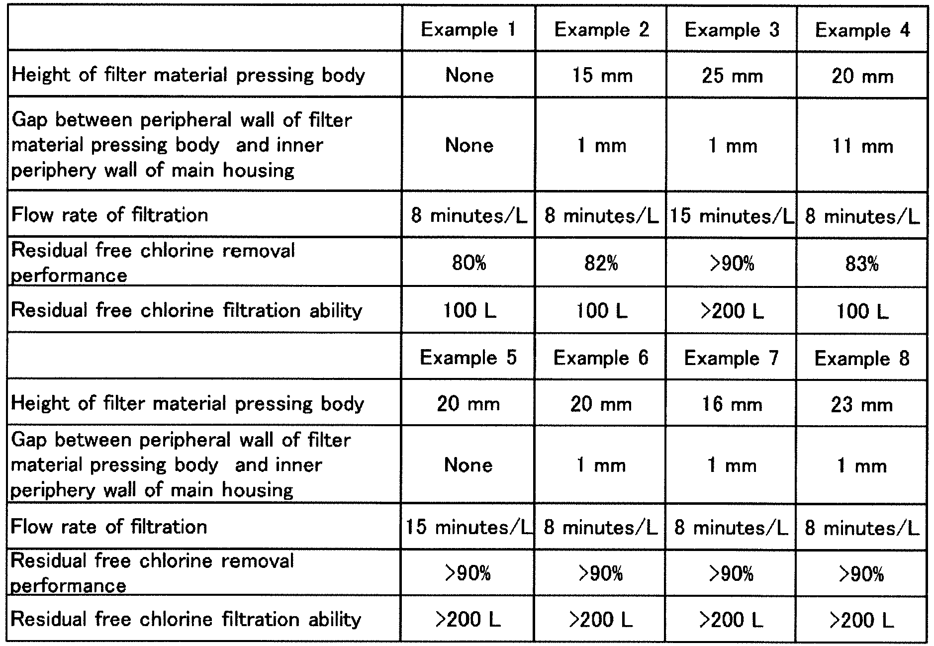
- The present invention can provide a water purification cartridge in which the content of a filter material and the like can be increased while minimizing the increase in the volume of the water purification cartridge, thereby preventing the decrease in the capacity of a purified water reservoir, and further minimizing the increase in the material cost. Thus it is extremely useful in industry.
-
- 1:
- Water purifier
- 2:
- Outer container
- 2a:
- Purified water reservoir
- 3:
- Inner container
- 3a:
- Raw water reservoir
- 3c:
- Bottom opening
- 4, 4A:
- Water purification cartridge
- 5:
- Container lid
- 6:
- Main housing
- 6a:
- Top end opening
- 6d:
- Top end opening rim
- 6e:
- Outer rim of main housing
- 7:
- Lid body
- 7a:
- Ceiling wall
- 7b:
- Peripheral wall
- 10:
- Filter material
- 11:
- Hollow fiber membrane (Porous filtration membrane)
- 61:
- Raw water inlet
- 62:
- Purified water outlet
- 71:
- Attachment cylinder (Attachment portion)
- 72:
- Filter material pressing body
- 73:
- Opening
- O:
- Container axis
Claims (20)
- A water purification cartridge comprising a main housing and a lid body,
wherein the main housing has a cylindrical shape with a bottom having an opening at a top end in a direction of a container axis, contains a filter material and a porous filtration membrane therein, and comprises a raw water inlet at an upper cylinder part of the main housing, and
wherein the lid body comprises an attachment portion to be detachably attached to the top end opening of the main housing, and is configured to close the top end opening of the main housing. - The water purification cartridge according to claim 1, wherein a convex surface protruded upward is formed at a ceiling wall of the lid body.
- The water purification cartridge according to claim 1 or 2, wherein the lid body comprises a filter material pressing body extending toward a bottom side of the main housing at the ceiling wall so that the filter material is pressed when the lid body is attached to the main housing.
- The water purification cartridge according to any one of claims 1 to 3, wherein the minimum value of distances between intersections of any straight line perpendicular to the container axis and a peripheral wall of the lid body is larger than the maximum value of distances between intersections of any straight line perpendicular to the container axis and the top end opening of the main housing.
- The water purification cartridge according to claim 4, wherein the difference between the minimum value of distances between the intersections of any straight line perpendicular to the container axis and the peripheral wall of the lid body and the maximum value of distances between the intersections of any straight line perpendicular to the container axis and the top end opening of the main housing is 1 mm to 30 mm.
- The water purification cartridge according to any one of claims 1 to 5, wherein a through hole communicating with the inside and the outside of the water purification cartridge is formed in the lid body.
- The water purification cartridge according to any one of claims 2 to 6, wherein at least one of an inner side or an outer side of the ceiling wall of the lid body forms an inclined surface gradually inclined upward as approaching to an apex convexed toward the central axis of the lid body from the peripheral wall of the lid body.
- The water purification cartridge according to any one of claims 2 to 6, wherein at least one of the inner side or the outer side of the ceiling wall of the lid body forms a step as approaching to the apex convexed toward the central axis of the lid body from the peripheral wall of the lid body.
- The water purification cartridge according to any one of claims 3 to 8, wherein the filter material pressing body has a cylindrical shape having an opening on a side.
- The water purification cartridge according to any one of claims 3 to 9, wherein the maximum value of lengths of the filter material pressing body in the direction of the container axis is 16 to 24 mm.
- The water purification cartridge according to any one of claims 3 to 10, wherein a gap between an outer rim of a cross section cut at any plane perpendicular to the direction of the container axis of the filter material pressing body and an inner rim of a cross section cut at any plane perpendicular to the direction of the main housing axis is 0.01 to 10 mm.
- The water purification cartridge according to any one of claims 1 to 11, wherein the filter material is contained in a bag-like article.
- The water purification cartridge according to any one of claims 1 to 12, wherein the filter material comprises a cation exchange resin.
- The water purification cartridge according to any one of claims 1 to 13, wherein the filter material comprises activated carbon.
- The water purification cartridge according to any one of claims 1 to 14, wherein the filter material comprises a chelating resin.
- The water purification cartridge according to any one of claims 13 to 15, wherein a filling factor of the filter material satisfies the formula:

- The water purification cartridge according to claim 16, wherein A/C defined as the ratio of A to C is 0.25 to 1.5.
- A water purifier comprising the water purification cartridge according to any one of claims 1 to 17, comprising:an outer container having a purified water reservoir, andan inner container having a raw water reservoir,wherein a bottom opening of the water purification cartridge is formed at a bottom wall of the inner container, andwherein the main housing is fitted to the bottom opening.
- The water purifier according to claim 18, wherein a fitting strength between the main housing and the lid body is larger than that between the bottom opening and the main housing.
- A filter material wherein at least one adsorbent selected from the group consisting of a cation exchange resin and activated carbon is contained in a bag-like article, the bag-like article comprising a non-woven fabric having a weight per area of 20 to 60 g/m2 and a fiber diameter of 2.2 to 6.6 dtx.
Applications Claiming Priority (2)
| Application Number | Priority Date | Filing Date | Title |
|---|---|---|---|
| JP2012210731 | 2012-09-25 | ||
| PCT/JP2013/075851 WO2014050860A1 (en) | 2012-09-25 | 2013-09-25 | Water purification cartridge and water purifier |
Publications (2)
| Publication Number | Publication Date |
|---|---|
| EP2902367A1 true EP2902367A1 (en) | 2015-08-05 |
| EP2902367A4 EP2902367A4 (en) | 2015-10-28 |
Family
ID=50388257
Family Applications (1)
| Application Number | Title | Priority Date | Filing Date |
|---|---|---|---|
| EP13841789.4A Withdrawn EP2902367A4 (en) | 2012-09-25 | 2013-09-25 | WATER PURIFICATION CARTRIDGE AND WATER PURIFIER |
Country Status (6)
| Country | Link |
|---|---|
| EP (1) | EP2902367A4 (en) |
| JP (1) | JP5757342B2 (en) |
| CN (1) | CN104703924A (en) |
| RU (1) | RU2630534C2 (en) |
| TW (1) | TWI549734B (en) |
| WO (1) | WO2014050860A1 (en) |
Cited By (3)
| Publication number | Priority date | Publication date | Assignee | Title |
|---|---|---|---|---|
| CN106542663A (en) * | 2016-10-17 | 2017-03-29 | 东莞市倍益清环保科技有限公司 | A high-flow rate filter element for water purification |
| EP3178790A1 (en) * | 2015-12-10 | 2017-06-14 | Brita GmbH | Cartridge for a fluid treatment system and use thereof |
| WO2026046535A1 (en) * | 2024-08-28 | 2026-03-05 | Eternal-Water Aps | Device for purifying water |
Families Citing this family (8)
| Publication number | Priority date | Publication date | Assignee | Title |
|---|---|---|---|---|
| JP6606684B2 (en) * | 2015-07-09 | 2019-11-20 | 公立大学法人大阪 | Metal recovery bag, metal recovery package, and metal recovery method |
| TWI635900B (en) * | 2017-07-11 | 2018-09-21 | 羅英維 | Method for using purified water sludge as raw material as arsenic and fluorine adsorbent |
| JP7332756B2 (en) * | 2018-02-07 | 2023-08-23 | 三菱ケミカル・クリンスイ株式会社 | water purifier |
| JP7227057B2 (en) * | 2019-03-29 | 2023-02-21 | 三菱ケミカル・クリンスイ株式会社 | Pretreatment method for water purification cartridge |
| MX2023000566A (en) * | 2020-07-13 | 2023-03-15 | Evoqua Water Tech Llc | Regenerative media filter with flow diffuser. |
| JP2022155906A (en) * | 2021-03-31 | 2022-10-14 | 三菱ケミカル・クリンスイ株式会社 | Water treatment cartridge, water treatment device, method for producing treated water, and device with water treatment function |
| CN113476945A (en) * | 2021-08-06 | 2021-10-08 | 慈溪市夏蒙电器有限公司 | Filter element of water purifying kettle |
| CN116496793A (en) * | 2023-05-08 | 2023-07-28 | 北京化工大学 | Flexible hydrotalcite soil remediation adsorption package and its preparation method and application |
Family Cites Families (24)
| Publication number | Priority date | Publication date | Assignee | Title |
|---|---|---|---|---|
| DE3304152A1 (en) * | 1982-02-10 | 1983-08-18 | Dieter Dipl.-Chem. 4000 Düsseldorf Brodalla | Process and apparatus for treating domestic water |
| GB2175777A (en) * | 1985-05-24 | 1986-12-03 | Still & Sons Ltd W M | Improvements in and relating to water purifiers |
| DE3819000A1 (en) * | 1988-06-03 | 1989-12-14 | Hasso Von Bluecher | Bag of a teabag type for eliminating pollutants |
| JPH0422488A (en) * | 1990-05-16 | 1992-01-27 | Kao Corp | Water purifier |
| JP2777466B2 (en) * | 1990-07-31 | 1998-07-16 | 三洋電機株式会社 | Industrial robot |
| JPH0487793U (en) * | 1990-11-30 | 1992-07-30 | ||
| JPH07222971A (en) * | 1992-06-26 | 1995-08-22 | Kuraray Chem Corp | Cartridge for water purifier |
| DE69306957D1 (en) * | 1992-08-14 | 1997-02-06 | Levene Ltd William | CAN WITH FILTER |
| US5637214A (en) * | 1995-11-09 | 1997-06-10 | Kahana; Dov | Filter assembly for water treatment apparatus |
| DE19952757A1 (en) * | 1999-11-02 | 2001-05-03 | Brita Gmbh | Filter device for liquids |
| GB9929349D0 (en) * | 1999-12-13 | 2000-02-02 | Crompton J R Plc | Beverage infusion packages and materials therefor |
| EP1354857B1 (en) * | 2000-12-25 | 2008-02-20 | Mitsubishi Rayon Co., Ltd. | Pitcher type water purifier and purification cartridge for the water purifier |
| JP2004174357A (en) * | 2002-11-26 | 2004-06-24 | Matsushita Electric Works Ltd | Water cleaning cartridge and water cleaner |
| JP4863425B2 (en) | 2003-01-31 | 2012-01-25 | 三菱レイヨン株式会社 | Water purification cartridge and water purifier |
| US20050136155A1 (en) * | 2003-12-22 | 2005-06-23 | Jordan Joy F. | Specialty beverage infusion package |
| RU74822U1 (en) * | 2007-02-12 | 2008-07-20 | Закрытое Акционерное Общество (ЗАО) "МЕТТЭМ-Технологии" | FILTER CARTRIDGE |
| CN101302046B (en) * | 2008-05-11 | 2010-09-29 | 黄樟焱 | Dynamic water treatment material normal pressure water purifier |
| JP5466843B2 (en) * | 2008-10-30 | 2014-04-09 | 倉敷繊維加工株式会社 | Method for producing laminated nonwoven fabric for air filter |
| JP4915820B2 (en) * | 2008-11-14 | 2012-04-11 | パナソニック株式会社 | Water purification cartridge and water purifier |
| JP5904717B2 (en) * | 2010-05-10 | 2016-04-20 | エア・ウォーター株式会社 | Drinking water server |
| JP5691089B2 (en) * | 2010-07-27 | 2015-04-01 | 大阪ガスケミカル株式会社 | Water purification cartridge and water purifier equipped with the water purification cartridge |
| US8828895B2 (en) * | 2010-08-25 | 2014-09-09 | Nonwoven Network LLC | Webs of bi-component and mono-component Co-PLA fibers |
| RU2618826C2 (en) * | 2011-02-09 | 2017-05-11 | Мицубиси Рейон Клинсуй Компани, Лимитед | Water purification cartridge and water purification device of jug type |
| RU115236U1 (en) * | 2011-03-25 | 2012-04-27 | Юрий Ефремович Андриевич | UNIVERSAL FILTER CASSETTE |
-
2013
- 2013-09-24 TW TW102134307A patent/TWI549734B/en not_active IP Right Cessation
- 2013-09-25 RU RU2015114170A patent/RU2630534C2/en not_active IP Right Cessation
- 2013-09-25 EP EP13841789.4A patent/EP2902367A4/en not_active Withdrawn
- 2013-09-25 JP JP2013547739A patent/JP5757342B2/en not_active Expired - Fee Related
- 2013-09-25 WO PCT/JP2013/075851 patent/WO2014050860A1/en not_active Ceased
- 2013-09-25 CN CN201380050093.2A patent/CN104703924A/en active Pending
Cited By (5)
| Publication number | Priority date | Publication date | Assignee | Title |
|---|---|---|---|---|
| EP3178790A1 (en) * | 2015-12-10 | 2017-06-14 | Brita GmbH | Cartridge for a fluid treatment system and use thereof |
| WO2017097494A1 (en) * | 2015-12-10 | 2017-06-15 | Brita Gmbh | Cartridge for a fluid treatment system and use thereof |
| CN106542663A (en) * | 2016-10-17 | 2017-03-29 | 东莞市倍益清环保科技有限公司 | A high-flow rate filter element for water purification |
| CN106542663B (en) * | 2016-10-17 | 2018-08-28 | 东莞市倍益清环保科技有限公司 | High-flow-rate water purification kettle filter element |
| WO2026046535A1 (en) * | 2024-08-28 | 2026-03-05 | Eternal-Water Aps | Device for purifying water |
Also Published As
| Publication number | Publication date |
|---|---|
| WO2014050860A1 (en) | 2014-04-03 |
| TWI549734B (en) | 2016-09-21 |
| JPWO2014050860A1 (en) | 2016-08-22 |
| EP2902367A4 (en) | 2015-10-28 |
| CN104703924A (en) | 2015-06-10 |
| RU2630534C2 (en) | 2017-09-11 |
| RU2015114170A (en) | 2016-11-20 |
| TW201422297A (en) | 2014-06-16 |
| JP5757342B2 (en) | 2015-07-29 |
Similar Documents
| Publication | Publication Date | Title |
|---|---|---|
| JP5757342B2 (en) | Water purification cartridge, water purifier and filter media | |
| US20160136545A1 (en) | Water purification cartridge and water purifier | |
| JP5582194B2 (en) | Water purification cartridge and water purifier | |
| CN102510836B (en) | Water purifier | |
| JP5999453B2 (en) | Water purification cartridge | |
| US20140151304A1 (en) | Gravity fluid/water filter engine system | |
| JP4204777B2 (en) | Water purifier | |
| JP5609978B2 (en) | Water purification cartridge and water purifier | |
| JP5433704B2 (en) | Water purification cartridge | |
| JP5910749B2 (en) | Portable simple water purifier and its water purification cartridge | |
| RU2568730C1 (en) | Individual facility for liquid purification | |
| JP2020163325A (en) | Pretreatment method for water purification cartridge | |
| JP2022155906A (en) | Water treatment cartridge, water treatment device, method for producing treated water, and device with water treatment function | |
| JP2020131152A (en) | Water purification cartridge |
Legal Events
| Date | Code | Title | Description |
|---|---|---|---|
| PUAI | Public reference made under article 153(3) epc to a published international application that has entered the european phase |
Free format text: ORIGINAL CODE: 0009012 |
|
| 17P | Request for examination filed |
Effective date: 20150319 |
|
| AK | Designated contracting states |
Kind code of ref document: A1 Designated state(s): AL AT BE BG CH CY CZ DE DK EE ES FI FR GB GR HR HU IE IS IT LI LT LU LV MC MK MT NL NO PL PT RO RS SE SI SK SM TR |
|
| AX | Request for extension of the european patent |
Extension state: BA ME |
|
| RA4 | Supplementary search report drawn up and despatched (corrected) |
Effective date: 20150928 |
|
| RIC1 | Information provided on ipc code assigned before grant |
Ipc: C02F 1/44 20060101ALI20150922BHEP Ipc: B65D 85/808 20060101ALN20150922BHEP Ipc: C02F 1/42 20060101ALI20150922BHEP Ipc: C02F 1/28 20060101AFI20150922BHEP |
|
| DAX | Request for extension of the european patent (deleted) | ||
| 17Q | First examination report despatched |
Effective date: 20160525 |
|
| RAP1 | Party data changed (applicant data changed or rights of an application transferred) |
Owner name: MITSUBISHI CHEMICAL CORPORATION |
|
| STAA | Information on the status of an ep patent application or granted ep patent |
Free format text: STATUS: THE APPLICATION IS DEEMED TO BE WITHDRAWN |
|
| RAP1 | Party data changed (applicant data changed or rights of an application transferred) |
Owner name: MITSUBISHI CHEMICAL CORPORATION |
|
| 18D | Application deemed to be withdrawn |
Effective date: 20170818 |